MPK4K-C-Ch03
佳能Canon墨盒型号对照表

适用于BJC-3000/BJC-6000/BJC-6200/BJC-6500
佳能BC-34照片
适用于BJC-3000/BJC-6000/BJC-6200/BJC-6500
佳能BC-50黑色
适用于BJC-8200
佳能BC-50彩色
适用于BJC-8200
佳能BC-60黑色
适用于BJC-7000/BJC-7100/BJC-8000
佳能BCI-24黑色
适用于S300/i320
佳能BCI-24彩色
适用于S300/i320
佳能BCI-201套
适用于BJC-600/BJC-610
佳能BCI-3PB/PC/PM
适用于BJC-3000/BJC-6000/BJC-6200/BJC-6500
佳能BCI-3照片
适用于BJC-3000/BJC-6000/BJC-6200/BJC-6500
佳能BCI-3彩色
适用于BJC-3000/BJC-6000/BJC-6200/BJC-6500
佳能BCI-3黑色
适用于BJC-3000/BJC-6000/BJC-6200/BJC-6500
佳能BCI-3e照片
适用于S400/S450
佳能BCI-3e彩色
适用于S400/S450
佳能BCI-3e黑色
适用于S400/S450
佳能BC-06照片
适用于BJC-1000SP/BJC-255SP/BJC-265SP/
佳能BC-09F彩色
适用于BJC-1000SP/BJC-255SP/BJC-265SP/
佳能BC-10黑色
适用于BJ30/BJC-50/BJC-55/BJC-70/BJC-80/BJC-85
喷墨打印机特性文件质量评测

哪一个色彩管理软件最精确并且能够再现最好的颜色值,显然各软件公司有不同的评价标准,致使大多数用户不能够独立地评价特性文件质量的好坏。
针对这一现状,本文对喷墨打印机生成 I C C 特性文件的色彩管理软件进行分析,通过具体实验提供当前软件产品独立的、客观的评价,从而为软件用户提供可靠的选择依据。
喷墨打印机输出设备特性文件中的颜色关系均以查找表记录,I C C 标准格式的输出特性文件中包含双向变换共6个查找表,它们分别是B T o A 0、A T o B 0、B T o A 1、A T o B 1、B T o A 2和A T o B 2,代表感知的、相对的和饱和度的双向变换,色彩管理技术中规定用A 代表设备颜色值,用B 代表设备连接色空间(P C S )的色度值,即 C I E L A B 或 C I E X Y Z 色度值。
本文通过色彩转换软件精确评价输出特性文件查找表的精度,即不通过打印的途径评价输出特性文件查找表的精度以避免产生测量等误差。
具体实施方法是将测量测试色靶得到的C M Y K 值经过色彩转换软件指定特性文件A T o B x 表转化成C I E L A B 2值,再将测量测试色靶得到C I E L A B 1值进行比较色差。
一、实验条件色彩管理软件包括P r o f i l e M a k e r 、I 1P r o f i l e r ,使用的设备为E p s o n 7880C 喷墨打印机,测试软件使用 P h o t o s h o p C S 6、C o l o r L a b 2.8.13完成。
二、实验过程1. P r o f i l e m a k e r 色彩管理打印机在P h o t o s h o p C S 6软件中打开指定的E C I 2002 C M Y K 色卡文件,点击“文件”菜单下的“打印”命令,在弹出的打印机属性设置页面“关 (无色彩调整)”选项,其他参数保持默认设置,设置好后打印色卡文件。
HP ProLiant DL580 Gen9 用户手册(中文)
Intel® 和 Xeon® 是 Intel Corporation 在美国和其它国家(地区)的商标。
Linux® 是 Linus Torvalds 在美国和其 它国家/地区的注册商标。
HPE ProLiant DL580 Gen9 服务器用户 指南
摘要 本文适合那些安装、管理服务器和存储系统以及 对其进行故障排除的人员使用。 Hewlett Packard Enterprise 假定您有资格维修计算机设备,并经 过培训,能够识别高压带电危险产品。
© Copyright 2015, 2016 Hewlett Packard Enterprise Development LP
2 操作 ................................................................................................................................................................. 19 打开服务器电源 .................................................................................................................................. 19 关闭服务器电源 .................................................................................................................................. 19 将服务器从机架中取出 ....................................................................................................................... 19 将服务器从机架中拉出 ....................................................................................................................... 20 卸下检修面板 ...................................................................................................................................... 21 安装检修面板 ...................................................................................................................................... 22 卸下 SPI 板 ......................................................................................................................................... 22 安装 SPI 板 ......................................................................................................................................... 23
理光A4打印机和中高端打印机维修模式进入方法
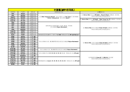
电源开启状态下同时按住[上],[下]键5秒或5秒以上放开,然后按下[OK],等到显示屏上显示 [SP mode(Service)]
电源关闭状态下同时按住[Online],[Escape],然后开机等到显示屏上显示[SP mode(Service)]
机器系列 PE-P1 PE-P1
Midas-P1 Rinmei-P1 Rinmei-P1
PE-P2 PE-P2 PE-P4 PE-P4 PE-P5 Rinmei-P2 Rinmei-P2 Mer-P1 PE-MF1 PE-MF1 PE-MF2 PE-MF3 PE-MF4 PE-MF5 Mer-MF1 Rinmei-MF1 Rinmei-MF2 Gimlet-MF1 Gimlet-MF1 Vesta-MF2 Metis-P2 Griffin-C2 Griffin-C3 Griffin-C4 CMY-MF1
产品型号 SPC220N SPC222DN SPC312DN SP3400N SP3410DN SPC240DN SPC242DN SPC250DN SPC252DN SPC261DNw SP3500N SP3510N PC300W SPC220S SPC221SF SPC231SF SPC242SF SPC252SF SPC261SFNw MC250FWB SP3400SF SP3500SF SP3610SF SP4510SF SPC360SFNw SPC840DN MPC406ZSP MPC407SP IMC400F IM430F
P501
机型分类 黑白A4打印机 黑白A4打印机 黑白A4打印机 黑白A3打印机 黑白A3打印机 黑白A3打印机 彩色A4打印机 黑白A4打印机 彩色A4打印机
CH7034B Fulll Datasheet Rev1.21

• Programmable adaptive de-flickering filter
LVDS transmitter. On-chip dithering function is
• Supports 8/12/16/18/24-bit parallel interface inputs available to convert 24-bit color to 18-bit color LCD
ROM (CH9904)
interface. The input video signal can be either interlaced
• Offered in a 88-pin QFN package
or non-interlaced data formats.
201-1000-025 Rev 1.21 05/11/2012
(2.3MHz – 64MHz)
HDTV/VGA outputs and LVDS display. RGB data
• IO Supply Voltages from 1.2V to 3.3V and SPC/SPD format such as 16-bit 5:6:5, 18-bit 6:6:6 or 24-bit 8:8:8
or flipped in horizontal/vertical position
mechanism to switch off the LCD instantly if input data
• Pixel-level color enhancement for brightness, is missing or unstable. The panel on/off sequences and
Meggitt MPC4 机器人保护卡型号M版特色说明书

Information contained in this document may be subject to Export Control Regulations of the European Union, USA or other countries. Each recipient of this document is responsible for ensuring that transfer or use of any information contained in this document complies with all relevant Export ControlRegulations. ECN N/A.MPC4Machinery protection card Type MPC4FEATURES»From the Vibro-Meter ® product line»Continuously online machinery protection card »Real-time measurement and monitoring using state-of-the-art DSP techniques» 4 dynamic signal inputs and 2 tachometer (speed) inputs, all individually programmable »Programmable broad-band and narrow-band filters»Simultaneous amplitude and phase monitoring in order tracking mode»Programmable Alert, Danger and OK set points »Adaptive Alert and Danger levels»Front panel BNC connectors for easy analysis of raw signals»7 front panel LEDs show status and alarms »Integrated power supply for many Vibro-Meter front-ends, including ICP accelerometers and proximity systems»Live insertion and removal of cards»Available in ‘standard’, ‘separate circuits’ and‘safety’ (SIL) versions‘Standard’MPC4‘Safety’MPC4Machinery protection card MPC4DESCRIPTIONMPC4 cardThe MPC4 machinery protection card is the central element in the VM600 series machinery protection system (MPS), from Meggitt Sensing Systems’Vibro-Meter® product line. This very versatile card is capable of measuring and monitoring up to four dynamic signal inputs and up to two speed inputs simultaneously.The dynamic signal inputs are fully programmable and can accept signals representing acceleration, velocity and displacement (proximity), among others. On-board multi-channel processing allows measurement of various physical parameters, including relative and absolute vibration, S max, eccentricity, thrust position, absolute and differential housing expansion, displacement and dynamic pressure.Digital processing includes digital filtering, integration or differentiation (if required), rectification (RMS, mean value, true peak or true peak-to-peak), order tracking (amplitude and phase) and measurement of the transducer-target gap.The speed (tachometer) inputs accept signals from a variety of speed sensors, including systems based on proximity probes, magnetic pulse pick-up sensors or providing TTL signals. Fractional tacho ratios are also supported.The calibration may be expressed in metric or imperial units. Alert and Danger set points are fully programmable, as are alarm time delay, hysteresis and latching. The Alert and Danger levels can be adapted as a function of the speed or any external information.A digital output is available internally (on the corresponding IOC4T card) for each alarm level. These alarm signals may be routed on a bus within the VM600 rack to drive relays on optional relay cards (such as the IRC4 and RLC16).The processed dynamic (vibration) signals and speed signals are available at the rear of the rack (on the front panel of the IOC4T) as analog output signals. Voltage-based (0to10V) and current-based(4to20mA) signals are provided.The MPC4 performs a self-test and diagnostic routine on power-up. In addition, the card’s built-in“OK System” continuously monitors the level of signals provided by the sensors and indicates any problem due to a broken transmission line, faulty transducer or conditioner.An LED indicator on the MPC4 front panel indicates whether a processing or hardware error has occurred. Six additional LEDs (one per input channel) indicate whether the OK System has detected a fault and whether an alarm has occurred on the channel.The MPC4 card is available in three versions: a‘standard’ version, a ‘separate circuits’ version and a ‘safety’ (SIL) version, all of which function as a card pair using an IOC4T input/o utput card.‘Standard’ and ‘safety’ (SIL) versions of the MPC4 Both the ‘standard’ version and the ‘safety’ (SIL) version of the MPC4 card are certified to IEC61508 and ISO13849.The ‘standard’ MPC4 card is the original version, intended for safety systems using a VM600 rack with a limited range of cards, that is, ‘standard’ MPC4/ IOC4T card pairs and RLC16 relay cards. It has a VME-compatible slave interface and is fully software configurable via RS-232 (on the front panel of the card) or VME.The ‘safety’ MPC4 card, also known as the MPC4 SIL, was developed to permit a wider range of installation options. Specifically, VM600 racks that also contain condition monitoring cards (such as the CMC16 and XMx16) and relay cards (such as the IRC4 and RLC16). To safety certify these configurations, it was necessary to ensure that the ‘safety’ MPC4 is isolated from the other cards in a VM600 rack, so that there is no possibility of its configuration being inadvertently modified. Therefore, the ‘safety’ (SIL) version of the MPC4 does not include a VME-compatible slave interface, nor does it provide all of the signal processing capabilities of the ‘standard’ MPC4 card (see Specifications –‘standard’ and ‘separate circuits’ MPC4 cards only on page6).Segregation of MPS and CMSThe VM600 rack, machinery protection cards, condition monitoring cards and associated software are designed for compliance with the machinery protection system (MPS) and condition monitoring system (CMS) “segregation” requirements of the API670 standard, which ensures that the functionality of the MPS does not depend on and is notMachinery protection cardMPC4 DESCRIPTION (continued)compromised in any way by the operation of the CMS.So although machinery protection cards and condition monitoring cards can easily share sensor signals from measurement chains, MPC4/IOC4T card pairs do not share any communication buses with XMx16/XIO16T condition monitoring card pairs in a VM600 rack, and MPC4/IOC4T card pairs are configured and operated using the VM600 MPSx software (while XMx16/XIO16T card pairs are configured and operated using the VibroSight® software).Applications informationThe MPC4 cards are highly suitable for machinery protection in a wide range of industrial applications. For further information on the use of MPC4 cards, refer to the VM600 Functional Safety Manual MAVM600-FS/E. For specific applications, contact your nearest Meggitt Sensing Systems representative.SPECIFICATIONS – ALL MPC4 CARDSDynamic signal inputsNumber of inputs:4 per MPC4 cardDC range:0 to +20 V or 0 to −20 VAC range:±10 V (maximum)Common mode voltage range:−50 to +50 VCMRR:>60 dB at 50 HzCrosstalk:−72 dBInput impedance:200 kΩCurrent input range•DC signals:0 to 25 mA•AC signals:±8 mA (maximum)Analog AC frequency band(without integration):0.1 Hz to 10 kHzAnalog AC frequency band(with integration):2.5 Hz to 10 kHzAnalog frequency band for throughput toother cards and buffered AC outputs:DC to 60 kHz (−3 dB)Current measuring resistor:324.5ΩProcessing optionsBroad-bandFiltering options:High-pass, low-pass or band-passLP/H P ratio in pass band:500 (maximum)Ripple:±0.3 dBSlope:6 to 60 dB/o ctave (software configurable) Attenuation outside pass band:>50 dBAmplitude accuracy:±1% of full-scaleLinearity error:<±1%Equivalent input noise(without integration):<200 µV RMSMachinery protection card ArrayMPC4SPECIFICATIONS – ALL MPC4 CARDS(continued)Narrow-band (tracking)The ‘standard’ and ‘separate circuits’ versions of the MPC4 card support narrow-band tracking (see Specifications – ‘standard’ and ‘separate circuits’ MPC4 cards only on page6).The ‘safety’ MPC4 card does not support narrow-band tracking.Relative shaft vibrationFrequency band•Vibration:0.1 Hz to 10 kHz•Gap/p osition:DC to 1 HzAmplitude accuracy•Vibration:±1.2% of full-scale•Gap/p osition:±1% of full-scale•Linearity error:<±1%Initial gap/o ffset compensation:AvailableBuffered (raw) dynamic signal outputsThese signals are available on the MPC4 card’s BNC outputs and the IOC4T card’s raw outputs.Frequency range:DC to 10 kHz (−0.1 dB or 1%).DC to 60 kHz (−3 dB).Admissible load on output:>50 kΩAmplitude error:<2%Phase error:<5° (DC to 10 kHz)Transfer ratio•Voltage input:1 V/V•Current input:0.3245 V/m ASpeed/p hase reference inputs and outputsThe ‘standard’ and ‘separate circuits’ versions of the MPC4 card support speed/p hase reference inputs and outputs (see Specifications – ‘standard’ and ‘separate circuits’ MPC4 cards only on page6).The ‘safety’ MPC4 card does not support speed/p hase reference inputs and outputs.Alarm programmingLevel detectors•Vibration systems:Over-level switching (A+, D+) and under-level switching (A−, D−)•Accelerometer systems:Over-level switching (A+, D+)•Speed channel:2 Alert levels (A−, A+)Alarm scanning interval:100 ms (maximum)Alarm level value:User-programmable within rangeHysteresis:User-programmable within rangeLatching:User-programmable within rangeAlarm delay time:User-programmable within rangeAlarm outputs:Individual alarms and common alarms (open-collector transistor) Adaptation criteria (for adaptive:Speed or digital inputmonitoring)Logical combinations:AND, OR, majority voting logicNumber of logical combinations:8 basic functions and 4 advanced functionsMachinery protection cardMPC4 SPECIFICATIONS – ALL MPC4 CARDS(continued)OK systemRange:−20 to +20 VOperating principle•Powered sensors:DC voltage monitoring (open circuit and short circuit line check)•Unpowered sensors:Open circuit line check onlyTransducer power supplyVoltage power supply:+27.2 V ±5% in the range 0 to 25 mA.−27.2 V ±5% in the range 0 to 25 mA.+15.0 V ±5% in the range 0 to 25 mA.Current power supply: 6.16 mA ±5% in the range 1 to 23 VOver-current protection (on-board):11.0 A on +5 V linePower supply to MPC4 cardSupply voltage:5 V DC ±5% and ±12 V DCConsumption from +5 V DC supply:12.5 W, plus an additional 1 W per sensor usedConsumption from ±12 V DC supply:2.5 W (maximum)CommunicationsVME bus:D16 / A24 slave mode.The ‘standard’ and ‘separate circuits’ versions of the MPC4 card includea VME bus. The ‘safety’ MPC4 card does not include a VME bus.RS-232 port:Configuration port, proprietary protocolBus to IOC4T card:IP (Industry Pack)Notes: The ‘standard’ and ‘separate circuits’ versions of the MPC4 card are fully software configurable viaRS-232 or VME. The ‘safety’ MPC4 card is fully software configurable via RS-232 only.EnvironmentalOperating•Temperature:−25 to +65°C (−13 to +149°F)•Humidity:0 to 90% non-condensingStorage•Temperature:−40 to +85°C (−40 to +185°F)•Humidity:0 to 95% non-condensingPhysicalHeight:6U (262 mm, 10.3 in)Width:20 mm (0.8 in)Depth:187 mm (7.4 in)Weight:0.40 kg (0.88 lb)Machinery protection cardMPC4SPECIFICATIONS – ‘STANDARD’ AND ‘SEPARATE CIRCUITS’ MPC4 CARDS ONLYProcessing optionsNarrow-band (tracking)Constant Q filter:Q = 28Frequency range:0.15Hz to 10kHzMax. frequency ratio in selected band:f upper / f lower = 25Rate of change of speed:450 Hz/s ec. (in band 25 to 500 Hz)Order extraction:1/3X, 1/2X, 1X, 2X, 3X, 4XPhase error:<±6° maximum.<±1° typical (with order = 1X).Amplitude accuracy:±1.2%Linearity error:<±1%Speed/p hase reference inputsNumber of inputs:2 per MPC4 cardTriggering method:Crossing of thresholds on rising/f alling edge of signalTriggering thresholds:Rising = 2/3 of peak-peak value, falling = 1/3 of peak-peak valueTacho range:0.016Hz to 50kHz on input.0.016Hz to 1092Hz (1 to 65535RPM) after division by the“wheel teeth number”.Speed resolution:0.001 Hz (internal)Input voltage range:0.4 to 500 Vpp in the range 0.3 Hz to 10 kHz.2.0 to 500 Vpp in the range 10 kHz to 50 kHz.Minimum input voltage for reliable detection•Square-wave input signal:0.8 Vpp (0.016 Hz to 10 kHz).2.0 Vpp (10 kHz to 50 kHz).•Sinusoidal input signal:10 Vpp (0.016 Hz to 1 Hz).2.0 Vpp (1 Hz to 10 Hz).0.8 Vpp (10 Hz to 10 kHz).2.0 Vpp (10 kHz to 50 kHz).Range of DC component:−20 to +20 VFor speed/phase reference input channels, it can be more difficult to achieve the minimum input voltage required when current is selected as the signal transmission mode. Therefore, the 200Ω current-to-voltage conversionresistor used by the MPC4 card for current-modulated input signals should be used in any system designcalculations in order to ensure reliable detection.Speed/p hase reference outputsBNC outputs:TTL compatibleOutputs to IOC4T and:TTL compatibleTacho Bus (VM600 rack)Speed resolution:1 RPM (external)Machinery protection cardMPC4Headquartered in the UK, Meggitt PLC is a global engineering group specializing in extreme environment components and smart sub-systems for aerospace, defence and energy markets.Meggitt Sensing Systems is the operating division of Meggitt specializing in sensing and monitoring systems, which has operated through its antecedents since 1927 under the names of ECET, Endevco, Ferroperm Piezoceramics, Lodge Ignition, Sensorex, Vibro-Meter and Wilcoxon Research. Today, these operations areintegrated under one strategic business unit called Meggitt Sensing Systems, headquartered in Switzerland and providing complete systems, using these renowned brands, from a single supply base.The Meggitt Sensing Systems facility in Fribourg, Switzerland was formerly known as Vibro-Meter SA, but is now Meggitt SA. This site produces a wide range of vibration and dynamic pressure sensors capable of operation in extreme environments, leading-edge microwave sensors, electronics monitoring systems and innovative software for aerospace and land-based turbo-machinery.All statements, technical information, drawings, performance rates and descriptions in this document, whilst stated in good faith, are issued for the sole purpose of giving an approximate indication of the products described in them, and are not binding on Meggitt SA unless expressly agreed in writing. Before acquiring this product, you must evaluate it and determine if it is suitable for your intended application. Unless otherwise expressly agreed in writing with Meggitt SA, you assume all risks and liability associated with its use. Any recommendations and advice given without charge, whilst given in good faith, are not binding on Meggitt SA.Meggitt Sensing Systems takes no responsibility for any statements related to the product which are not contained in a current Meggitt Sensing Systems publication, nor for any statements contained in extracts, summaries, translations or any other documents not authored by Meggitt Sensing Systems. We reserve the right to alter any part of this publication without prior notice.In this publication, a dot (.) is used as the decimal separator and thousands are separated by thin spaces. Example: 12 345.678 90.Sales officesYour local agent Head officeMeggitt Sensing Systems has offices in more than 30 countries. For a complete list, please visit our website.Meggitt SARoute de Moncor 4PO Box 1616CH - 1701 FribourgSwitzerland Tel: +41 26 407 11 11Fax: +41 26 407 13 01ABCDISO 9001FS584089ORDERING INFORMATION To order please specify Type DesignationOrdering number MPC4Machinery protection card: ‘Standard’ version200-510-SSS-1Hh ‘Separate circuits’ version, in accordance with CEI / I EC 60255-5200-510-SSS-2Hh ‘Safety’ (SIL) version, safety certified in accordance with IEC 61508 and ISO 13849200-510-SSS-3HhNote: “SSS” represents the firmware (embedded software) version and “Hh” the hardware version. “H” increments are for major modifications that can affect product interchangeability. “h” increments are for minor modifications that have no effect on interchangeability.。
步科Kinco 低压伺服驱动器使用手册
第 2 章 系统安装要求与注意事项.................................................................................................................................4
2.1 驱动器安装.......................................................................................................................................................... 4 2.1.1 安装尺寸..................................................................................................................................................... 4
请确认驱动器各种端子是否齐全,以及电机油封和键是否齐全。
产品外观是否有损伤?
请确认产品是否在运输过程中有损坏。
如以上任一项有问题,请与本公司或您的供货商联系解决。
Kinco 低压伺服驱动器使用手册
目录
ቤተ መጻሕፍቲ ባይዱ
目录
前言 产品确认.................................................................................................................................................................0
HP LaserJet MFP M72625、M72630 系列打印机 用户指南说明书

Google ™ 是 Google Inc.的商标。
Microsoft®、Windows®、Windows® XP 和 Windows Vista® 是 Microsoft Corporation 在美国的注册商标。
此处包含的信息如有更改,恕不另行通 知。
HP 产品及服务的保修仅以随该产品及 服务提供的书面保修声明为准。本文所 述任何内容不应被视为附加保修。对任 何技术或编辑错误或者本文所述内容的 遗漏,HP 不承担任何责任。
Edition 2, 1/2019
商标声明
Adobe®、Adobe Photoshop®、Acrobat® 和 PostScript® 是 Adobe Systems Incorporated 的商标。
LaserJet MFP M72625、 M72630 系列打印机 用户指南
HP LaserJet MFP M72625、M72630 系列打 印机
用户指南
版权和许可证
© Copyright 2018 HP Development Company, L.P.
未经事先书面许可,严禁进行任何形式 的复制、改编或翻译,除非版权法另有 规定。
UNIX® 是 The Open Group 的注册商标。
目录
1 简介 ...................................................................................................................................................................
- 1、下载文档前请自行甄别文档内容的完整性,平台不提供额外的编辑、内容补充、找答案等附加服务。
- 2、"仅部分预览"的文档,不可在线预览部分如存在完整性等问题,可反馈申请退款(可完整预览的文档不适用该条件!)。
- 3、如文档侵犯您的权益,请联系客服反馈,我们会尽快为您处理(人工客服工作时间:9:00-18:30)。
Chinese MPK 4000 版本 1.08主菜單結構Chapter 03 Rev.-Date: 10 Aug 1999Contents 目錄1. Menu Structure 主菜單結構 (2)1.1. M ain Menu ‘information’ 訊息說明 (2)1.2. Main Menu ‘see / give calls’ 檢視及提供指令說明 (3)1.3. M ain Menu ‘code No.’ 代碼說明 (4)1.4. M ain Menu ‘basic Settings’ 基本設定說明 (4)1.5. M ain Menu ‘settings’ 設定說明 (5)Chinese MPK 4000 版本 1.08主菜單結構Chapter 03 Rev.-Date: 10 Aug 19991. Menu Structure 主菜單結構1.1. Main Menu ‘information’ 訊息說明Information 訊息operation status 操作狀態event log 故障記錄display 顯示clear 清除print 列印current event print 列印現時故障display system 系統顯示clear system 系統清除系統列印parameter print 參數列印test modul 檢查模式BST - IOs BST 輸入輸出輸入輸出BST reserved output terminals 預留輸出端子BST reserved input terminals 預留輸入端子Net IO setup 輸入輸出設定modulelist 程序清單parking zone plan 停駐表DSC – stop position 停止位置group members 群控編號trip counterdisplay 顯示Chinese MPK 4000 版本 1.08主菜單結構Chapter 03 Rev.-Date: 10 Aug 1999Information (continued) 續前頁clear 清除終止running time counter 運行時間記錄display 顯示clear 清除終止lift / control No. 電梯 / 控制屏編號set controller No. 設定控制屏編號clear controller No. 清除控制屏編號set lift No. 設定電梯屏編號清除電梯屏編號date / time display 日期 / 時間顯示lift 4000operating system 控制屏系統DSK – Program DSK 程式Menu program 主程式程序軟件1.2. Main Menu ‘see / give calls’ 檢視及提供指令說明see / give calls 檢視及提供指令level 1 – 64 層數1 – 64模擬指令程式Car calls 內呼Landing calls UP 外呼上外呼下Chinese MPK 4000 版本 1.08主菜單結構Chapter 03 Rev.-Date: 10 Aug 19991.3. Main Menu ‘code No.’代碼說明Code No. 代碼user log on 用戶代碼使用user log off 用戶代碼取消user identity 用戶代碼確認用戶代碼更改1.4. Main Menu ‘basic Settings’基本設定說明basic settings 基本設定lift 電梯No. of stops 層數lowest floor 最低層No. of car doors 轎門Table of Entrances 廳門表type of selector 選層器型號type of drive 馬達型號群組控制系統Landing calls 1-8 BST 外呼BST input BST 輸入BST output BST輸出Net input NET 輸入Net output NET 輸出Net calls NET 呼叫Input bounce timer 輸入時間Set time 時間設定Chinese MPK 4000 版本 1.08主菜單結構Chapter 03 Rev.-Date: 10 Aug 1999basic setting (continued) 續前頁Daylight savingtime 省電功能display line 1 顯示 1display line 2 顯示 2Data interface A 資料介面 Atransmission rate A 傳送 AData interface B 資料介面 Btransmission rate B 傳送 B語言1.5. Main Menu ‘settings’設定說明Settings 設定doors in general 門door open triggermech. locked timer 門釣時間lock bounce timerlock fault monitor 門釣不正常監察lock fault monitor 門釣不正常監察at the parking level 停駐層at homing level 基站層door nudging 迫關門door nudging afterlanding supervision controllimited door opening 開門限制door close button active 關門制起作用door reverse to callpre opening doors 提早開門Chinese MPK 4000 版本 1.08主菜單結構Chapter 03 Rev.-Date: 10 Aug 1999Setting (continued) 續前頁Firemans control int. button operat.? Schleusenschaltung bei Feuerwehrbetriebdoor control on inspection 檢修時門控制Door hold time 關門時間loading time pushed again 再按延遲關門制door monitor 門系統監察Photo cell monitor 光幕監察疏散層doors side 1 ... 轎門 1door reopen time car calls 內呼再開門時間door reopen time landing call 外呼再開門時間further travel delay reset photocell 光幕動作後再啟動時間door to park closed 停駐後關門door to park closed after 停駐後關門時間pause reverse delaydoor close timed out (autom.door with limits) 超過關門時間﹝帶極限開關的門﹞door open timed out (autom. door with limits) 超過開門時間﹝帶極限開關的門﹞waiting time at doorswitch UP (autom. door with limits)door motor OFF at rest (door without end limit)靜止狀態下門機關閉﹝不帶極限開關的門)靜止狀態下門機關閉﹝不帶極限開關的門)indicate/gong 顯示 / 到站鐘Display modules 顯示型號? selbstdef. Anzeigenfurther direction arrow in car 轎內繼續行駛方向Indicators off 顯示取消gong period 到站鐘響聲時間Chinese MPK 4000 版本 1.08主菜單結構Chapter 03 Rev.-Date: 10 Aug 1999Setting (continued) 續前頁gong on car calls 到站鐘﹝接應內呼﹞futher direction arrow flashing 繼續行駛方向燈閃動? Weiterfahrtanz. In Ruhe ausdirection arrow flashing 運行時方向燈閃動car calls flashing 運行時內呼燈閃動landing calls UP flashing 運行時外呼上行燈閃動landing calls DOWN flashing 運行時外呼下行燈閃動landing prior. Calls flashing 優先外呼閃動control functions 控制功能control type 控制種類main floor level 主層bottom floor return (hyd. lift) 返回最底層﹝液壓﹞bottom floor return timer (hyd. lift) 返回最底層時間﹝液壓﹞cold wealth starting (hyd. lift) 冬天起動﹝液壓﹞emergency stop 急停safety photo cell 光幕operator mode 司機控制signal attendant op.light delayed off 延遲關燈時間start of fan with button in car 轎內風扇開關風扇延遲開閉時間special-travels 特別功能homing floor 返回基站check floorevacuation service 疏散evacuation floor 疏散樓層evacuation service at 疏散訊號Chinese MPK 4000 版本 1.08主菜單結構Chapter 03 Rev.-Date: 10 Aug 1999Setting (continued) 續前頁firemans floor 消防層firemans travel specification 消防程序emergency power floor 應急電停靠層emergency power drive 應急電發機ringcontr. emergency power drive 應急電啟動次序start attemps emergency主電使用應急電繼續運行call operationcall cancellation direction depend 取消內呼取決於方向empty cab. LC offempty cab. car prio.empty car at landing prioritypriority-ready 優先時間landing priority fexible 外呼彈性優先程序more priorities 更多優先priority sorting 優先排序car prior. call via key switch 啟動優先程序啟動car prior. time 優先啟動時間max. car prio. calls 最多優先呼叫數量counter call canclcounter call clearcancelling of CTTLanti nusance 防擾亂功能outs selec. 2 entran. 選擇開啟後門call signal buffer 呼叫緩沖時間group operation 群控traffic pattern 特別運行程序time interval up peak 上行程序時間time interval dw. peak 下行程序時間Chinese MPK 4000 版本 1.08主菜單結構Chapter 03 Rev.-Date: 10 Aug 1999Setting (continued) 續前頁parking 停駐active 啟動parking program 停駐程序parking floor intern.parking floor extern.time interval 停駐啟動時間safety circuit 安全回路supervise 監察fault at 故障訊號故障處理horizontal selectorfloor levelpulse buffer delaypulse reaction timefloor counterimpulse in endlevelscorrection travel toshort floor distancesimpulse UP switchvertical selectorfloor levelpulse buffer delaypulse reaction timefloor counterChinese MPK 4000 版本 1.08主菜單結構Chapter 03 Rev.-Date: 10 Aug 1999Setting (continued) 續前頁impulse in endlevelscorrection travel toshort floor distancesimpulse UP switchdigital selector 數碼選層器absolute floor level 數層高度floor level difference 平層誤差floor level correction 修正平層誤差V 5 'off' UP V 5上行關閉距離V 5 'o ff’ DOWN V 5下行關閉距離V 4 'o ff’ UP V 4上行關閉距離V 4 'o ff’ DOWN V 4下行關閉距離V 3 'o ff’ UP V 3上行關閉距離V 3 'o ff’ DOWN V 3下行關閉距離V 2 'o ff’ UP V 2上行關閉距離V 2 'o ff’ DOWN V 2下行關閉距離V 1 'o ff’ UP V 1上行關閉距離V 1 'o ff’ DOWN V 1下行關閉距離V 0 'o f f’ UP V 0上行關閉距離V 0 'o ff’ DOWN V 0下行關閉距離start speed V 1 from 啟動 V 1速度的距離start speed V 2 from 啟動 V 2速度的距離start speed V 3 from 啟動 V 3速度的距離start speed V 4 from 啟動 V 4速度的距離start speed V 5 from 啟動 V 5速度的距離Output ref. pointDistance ref. pointChinese MPK 4000 版本 1.08主菜單結構Chapter 03 Rev.-Date: 10 Aug 1999Setting (continued) 續前頁total travel high 總行程pulse buffer delay 脈衝 - 緩沖時間correction journey to 校正位置時行駛至learning travel speed fast 學習行駛速度學習行駛啟動hydraulic lift 液壓電梯directstartY-D change over delayMotor delayed off afterinspection speeddelay afterthermistorvariable freq. AC VVVFV-fast delayed on after 快速延遲啟動時間contactor delayed off after 接觸器延遲關閉時間V-slow delayed off 慢速延遲關閉regulator fault 故障處理方式thermistor 熱感啟動oilthermistor-output 熱感訊號冷卻風扇travel monitors 行程監察contactor monitor active 接觸器start time monitor 啟動時間running time monitor 運行時間braking time monitor 剎車時間handling of faults 故障處理Mech. Brake fault 抱閘故障ChineseMPK 4000 版本 1.08主菜單結構Chapter 03 Rev.-Date: 10 Aug 1999Setting (continued) 續前頁Relevelling 再平層active 啟動 type (horizontal / vertical selector) 選層器型號 relevelling UP 'o n’ (digital selektor DSK ) 再平層 – 上啟動 relevelling UP 'o ff’(digital selektor DSK) 再平層 – 上關閉 relevelling DOWN 'o n’(digital selektor DSK) 再平層 – 下啟動 relevelling DOWN 'o ff’(digital selektor DSK) 再平層 – 上關閉 time limits 再平層 – 時間 max. time upwards 再平層 – 上時間 max. time downwards 再平層 – 下時間 attempt limits max. relevelling up 再平層 – 上次數 max. relevelling down 再平層 – 下次數 attempt limit in level 1 (hydr. lift) No. exceeded 超越再平層次數 handling of faults 故障處理 起載時間平層 door blocking 出入口鎖閉 block 鎖閉 鎖閉時間remote monitoring 邊控 Remote monitor ID 遙控器型號 RM-telephone no. 電話號碼 modem configuration 數據機 數據機基本設定。