ACS139MS中文资料
ABB ACS 140 说明书

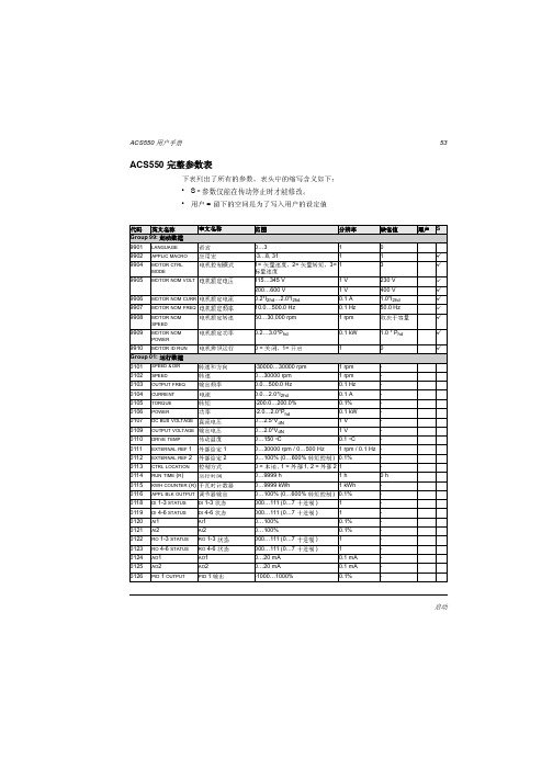
Comp-ACיACS140ɾ0.12 to 2.2 kWACS 140 变频器用户手册英文:3BFE 64273736 R0125中文:3ABD00008840 版本:C生效: 2002年11月20日© 2000 ABB Industry Oyɤų@ޱ Æ ៛ ACS140Þų ]Ɣ૫ ૫B Ϝ 0૫ Þ૫ ´҈B% 5ǒ. ҈ 1 Þ ƺஊ (U c+, U c-) ૫ ÞɮĨGÞ!૫Çឆ B%Ϝ ]Ɣ (U1, V1, W1 U2, V2, W2 > U c+, U c-) ड़ޱ 0૫ ϜÞ! ACS140 ´૫B%Ϝో૫ ( DO1A, DO1B, DO2A, DO2B) ड़@ŏޱLჼ 0૫ Þ! ACS140 ¼@ Ϝਲc ៝%ά _ ੪ ៝% %ƺܒޢ ܒ ៝Þ! )ɤ૫ ´૫ B ݀% Lჼႆ ؟ ON% ACS140 BŘǼ ǼÞ! ACS100/140/400 هǰ ݀% هǰƧم )ǽ૫ ŘB ៝ׄLჼ૫ Þ!ɮ ɾޢׄ ޢ܇B H ACS140 ŏ ¬ % Ԝ ܇ɾ > ƚ ɤÞųACS140 ޱ ŘǼ ŏÞ Ⴍ؍ŘǼ ŏ%ɾ BϜ 0ɷĕBŘǼ ƺܒ¬ C& ႏ ŏ ¬ ɷĕƜ %ĕൽ ൾ 0݀% 7 ŏÞų ê ࠩђ@ŏ ɮĨR Þų มɼ శ Æ % Þiii目录安全注意事项 (i)安装 (1)安装指导 (2)环境限制 (2)外形尺寸 (mm) (2)安装 ACS140 (3)打开塑料外壳 (6)粘贴警告标牌 (6)电缆连接 (6)端子与接口 (7)铭牌标识 (8)浮地电网 (8)电机 (8)控制端子 (9)连接示例 (10)复原外壳 (10)通电 (11)保护特性 (11)电机过载保护 (12)ACS140负载能力 (12)型号和技术数据 (13)产品规范 (18)环保要求 (18)附件 (19)编程 (21)控制盘 (21)控制模式 (21)输出显示 (22)菜单结构 (22)设定参数值 (22)菜单功能 (23)故障诊断显示 (23)故障复位 (24)ACS140 基本参数 (25)应用宏 (29)应用宏 Factory (0) (30)应用宏 Factory (1) (31)应用宏- ABB 标准型 (32)应用宏-三线型 (33)应用宏-交变型 (34)iii应用宏-电动电位器型 (35)应用宏-手动/自动型 (36)应用宏- PID 控制 (37)应用宏-预磁通 (38)ACS140 完整参数表 (39)Group 99:起动数据 (44)Group 01:运行数据 (45)Group 10:指令输入 (47)Group 11:给定选择 (49)Group 12:恒速运行 (52)Group 13:模拟输入 (53)Group 14:继电器输出 (54)Group 15:模拟输出 (55)Group 16:系统控制 (56)Group 20:限幅 (57)Group 21:起动/停止 (58)Group 22:加速/减速 (60)Group 25:危险频率 (61)Group 26:电机控制 (62)Group 30:故障功能 (64)Group 31:自动复位 (68)Group 32:监控器 (69)Group 33:信息 (72)Group 40:PID 控制 (73)Group 52:通讯 (79)故障诊断 (81)概述 (81)报警和故障显示 (81)故障复位 (81)ACS140 EMC 指导书 (85)附录 (91)本地控制与远程控制(内控与外控) (91)本地控制 (91)远程控制 (92)应用宏内部信号连接 (93)ACS140 售后服务说明 (95)iv1 శጁ ºÞ శጁ ޱ º%Ƨ>ޱ ɤ %ޱ@ŏ Hɾ ъ %ׄႸ־ ƚ L Þ123567891112Ą ACS140҈ L5 )ɤ૫ ૫Ç;ǒǼ هǰ DIP ҈ Ƨمهǰ૫ƧمǼ ૫L5ƫ૫ɮĨAɮĨ B, CɮĨ DɮĨ F, G, KɮĨ H, IɮĨ JɮĨ K,LɮĨ F, GɮĨ G, K, LɮĨ MɮĨ N104ɮĨ E2ɮಿA Ą 0ǰĄ ࠩђ& 0 - 40°C (0 - 30°C % ҈ = 16kHz) ި ࠩђ& 50°C źP N I 2 0Ǫ 80%% ҈ = 4kHz Ż ђ& 0 - 1000m ź P N I 2 100%Ż ђ&0 - 2000m ź 1000 m % 100 m P N I 2 0 1 % Ż எ; ђ& 95% ź1+ఽŻ ³ࠩђ& -40°C - 70°Cႆ)ࠩђ& -40°C - 70°CACS 140 Ϝࠑ %Ą %ܰࡪ cʜ% ܰ!&ԇׄ ૫ԇ N נ ణž Þ ዶ ኙ ÞB L : (mm)L :IP 20200V ǝƺƺ (kg)h1h2h3d1(d2)d1+d21~3~A 126136146117321490.90.8B 12613614611769186 1.2 1.1C 19820821811752169 1.6 1.5D 22523524512452176 1.9 1.8H 12613614611901190.8-400V ǝA 12613614611732149-0.8B 12613614611769186- 1.1C 19820821811752169- 1.5D 22523524512452176- 1.8H126136146119119-0.7d1 + d268(d2)h1d1h 2h 358803C ACS 140!ACS 140)ɤ૫ М´҈Þƪ ǝ L : A, B, C >D ŻACS 140 Ӊ ஊ % ܛ ܛൽG 25mm ዶ%ء B1R ჼǒƺ Æ ޱ ್źǼ ૫Ɣ هǰ૫ƔŻ % ޱྭ ơ Þؚt M4 .) (35 mm)ϜDIN ) % ݀% ء ჼÞ៸tACS140 ê @ Ϝƫ ƫ* %Ǽ ]Ɣ ĕ êƺ [ϜL 1%ƺ1@ هǰ]Ɣ ĕ êƺźɮĨRŻ Þܰ ê ǝ (L : H)! H ǝ ޱ ê % ACS140 ܰ ê ǝႦ Lჼ ê cʜ% ; ʜ ê Þ1ܰ ê ACS140 Ӊ Ϝ ܰ % Ƥ ᅏ 1B݀ ʜ ǝ &ި ђ 3 mm1 ɢࡓ ( 1ђ&0.1 %ɢ ђR a = 3.2 um )Æ5 or M44 holes45êޱŏ Bêƺ ɷǪĄ % ࠩђϜ ݀ Ƴ ŏ ႃ80°C Þృ- 1 ê 3mm ê źĄ ࠩђ40°C Ż݀% ್ƺ ; ި 1 % 3mm ¼ % 0 ʜ ê Lჼ ê Ƴ@ ACS140 ê ÞÇࠑ 1Ϝ ACS 140 ዶ ê! M4 .% 1-1.5 NmB%ƫႃ୳ ACS140 ࠩђźɮ 0110Ż [@ ê % ϜިW Ą ࠩђ #ႆ ݀%ACS140 ࠩђ ႃ 85°C % ê ¼־ Þɾ ʑ ್ (W)ި 1 H x W (mm x mm)ACS 141-H18-17150 x 150ACS 141-H25-110180 x 180ACS 141-H37-112200 x 200ACS 141-H75-113210 x 210ACS 141-1H1-119250 x 250ACS 141-1H6-127300 x 300ACS 143-H75-314220 x 220ACS 143-1H1-320260 x 260ACS 143-1H6-327300 x 300ACS 143-2H1-339500 x 500] M4 .ê!6D ҈ L5B݀ء ] ҈ L5Eȵ ޱʘ % Ⴍ؍Ԝ ፠ Ϝɾ L5 % G ź مʃŻ ÞF ૫Ƨمء Ϟ૫ ǟႭ؍ķ Þ૫Ç૫ Ż૫Þ૫Ç૫ ķ ƺ*҈هǰ૫ )ɤ૫ ૫% *១૫ )@Þ! ɮ 85 EMC ŴACS140 EMC ؟ ŴÞ¢ႚL, N எ૫ )ɤ _ ɮĨ* % எ ៝U1, V1, W1 எ૫ )ɤ எ૫ PE נϞި 4 mm 2 ǙķU2, V2, W2૫Ç)- ި/૫/ђɼƝ ʑ ɮĨ6 Uc+,Uc-ஊ ķ૫ 9مǰǼ ៝૫Ç૫ Ż1127G مʃWarning! Dangerous voltageWait 5 minutes afterdisconnecting supply before proceeding. See User's Manu al .ABBABB Industry OyACS143-4K1-1U13* 200...240 V U23*0..U1f150/60 Hz f20..300 Hz I112.0 AI29.0 AS/N 042A0001૫Ç)-ÜDC %ÜمǰǼ ៝Ż૫Ç૫Ļ1૫ )ɤ19هǰ DIP - ˬɮ K8H ǚI Ϟ૫૫૫ Ϟ૫ ( IT ૫ )% ǵӉɼ مϞ .( GND )%ʮǟ@ŏ ɷĕ 0ׄ ൾɾ ÞϜ Ϟ૫ ŏ RFI ࡠ %૫ @ŏƫႃࡠ ૫ Ϟ Ɣ% ņ@ŏ ĕ 0ׄ ൾ ɾ Þɾ ႆ ݀ ;Ưႇ ૫ ĕ H%ϜƫъԭƟ %ɾ ૫ Řड़ ǰ Мĸྭ Þ ႎ ϜǤ %@ ၻޱ1૫ Ż 0 ɾ ÞJ ૫Ç૫ǼʮႭ؍ʜႦÞ૫Ç ¼ எ ૫ǼÇ%U N 200 240V ׄ380 480V %f N 50Hz ׄ 60Hz % ૫Çɮ ޱ B%99ఴɮ ء૫Ç 0ɮ ܇Þ૫Ç ૫ I N ACS 140 )-૫ I 2Þ(ɮ H R )Þ)ɤ&ACS 141 = 1 ~ACS 143 = 3 ~ACS 141-xxx-1 = 200V ACS 141-xxx-3 = 400V &4K1 = 4.1kVA ƪ ǝ(L : A, B, C >D)4H1 = 4.1kVAܰ ê ǝ ( : H)ǝʑ&S/N 042A00010 = 2000 42 = 42 A0001= ჼ౨ʑGND9K هǰDIP ҈S1:1 S1:2 Ⴍ؍ )ɤ ʑA1 A2 ʑ U/I Þ S1 = U & S1 ҈= I Þ)ɤǩ 1.5k 9Þ )ķ% 1 0.5-1.5mm 2 ÞųDI 4ӭ Ϝ ૫݀ ɼ (Е 0 1)Þ! - ɤ ά%ACS140´૫݀ 0ో૫ ؟ j 0kӭÞ ų 3%6%8 ૫ Þʑ ¢ႚ1SCR ʑ૫ Ż ( ჼ Ç5எƧ)Þ2AI 1)ɤ1%@౨ ÞĿ&0 - 10V (R i = 190k 9 S1:1:U) <=> 0 - 50Hz )- 0(4) - 20mA (R i = 5009) (S1:1:I) <=> 0 - 50Hz )- ǒၰ 0.1%% ђB 1%Þ3AGND )ɤ៴៹ Þ(ƫႃ 1M 9.૫ǩ ϞஎƧ)Þ410 V 10 V % ృ ૫ ૫ ʑ% ђ -2%% 10mA Þ5AI 2)ɤ2%@౨ ÞĿ&0 - 10V (R i = 190k 9 S1:2:U) 0 - 20mA (R i = 5009) (S1:2:I)ǒၰ 0.1%% ђB 1%Þ6AGND )ɤ៴៹ Þ(ƫႃ 1M 9.૫ǩ ϞஎƧ)Þ7AO)-%@౨ ÞĿ&0-20 mA ( )< 5009) <=>0-50Hz ђB 3%Þ8AGND DI ʑ៴៹ Þ912 V )ǽ૫ )-12V DC Þ I max = 100mA (ɮ AGND)Þ ޱ Ɣ נÞ10DCOM)ɤDI ៴៹ Þ )ɤ DCOM ዶ૫ +12V ( ׄ-12V ) ݀ޱ Þ12V ૧ ACS 1 0 (X1: ) ׄ૧Lჼ૫ 12-24V ިW 28V ٞ (ɮĨ /)ÞDI + Factory (0)Factory (1)11DI 1 Ǽ. ૫B%૫Çء ǒޠķ Ǽ%[૫B%૫ÇB ԇឆ)Þ Ǽ. Ϝ', Ǥʜ݀ ', ݀ ૫૫Ç ǼÞ12DI 2>ʟ& ૫>)Þឆ & ء', ݀[૫%$&6 ឆ Þ13DI 3एǼ& ૫B%)-एǼ Þ(Ŀ&5Hz)Þ>ʟ& ૫>)Þ14DI 4 ૫ÞӉ ૫Þ15DI 5Ǵ/*ƫ݀ዶႭ؍(5s/60s)% ૫B%Ⴍ60s Þ16DO 1A @౨ ో૫ )-1 (Ŀ& 0)Þ0&DO 1A DO 1B ´҈Þ12 - 250V AC / 30V DC, 10mA - 2A 17DO 1B 18DO 2A @౨ ో૫ )-2 (Ŀ&ႆ )Þႆ & DO 2A DO2B ʺʜÞ12 - 250V AC / 30V DC, 10mA - 2A 19DO 2B10L Ƨمృ ʑ ૫ ʑ݀M L5Ϝƺܒ ƫ૫ÞDI + Factory (0)NPN Ƨم11N ƫ૫ACS 140ƫ૫B %LED Ļ ÞO נ ԇACS 140 ޱ נ ŏÞACS 140 ૧LED ؟ ס 0źLED ס ؟ ɮĨG Ż Þ ACS 100-PAN هǰƧمϜ %@ɮಿ81 j 0 ´k Þ! ܶACS 140 Ǫ 0ɷĕ% 0ో૫ Ǽ %૫Çឆ)%ɾ Þ 0 ஊ Ϝɴ -Lჼ ά% ACS 140 Þႃ נ ႃ נ נ ႃê נ)-مϞ נ )- Ɣ נ)ɤĿஎ נ (3~)Ɯ נ (500ms) I/O Ɣ נ ႃ ࿕ዺ0 110% ݀ႃ 0 150% ૫Çႃ) נ (ɮ P ) _) נఞ : Ļ :ǤऑҊ ъҊъ&.ACS 140 ŏ ɤƓ0هǰ؟ Þ.Ǥऑ15 Þ@ŏ ά&о)݀Ǵ/*ƫ݀ዶ ૫ ݀ ´ఞ : Ļ :0 Ɲܛ &ឆ % 0 ƺܒ Ǽ&Ǽ Æŏ Ǽ% ૫ ¼ʮϜ៛ Ǽ෫κ Þ@ŏ ά& ݀ႃ ႃ/ ႃê&)ɤ૫ ¼ʮ ъ Ç άҗ ႃ ê ¼ʮ Ƥఞ :ǤऑĻ :¬ &´҈૫ൽLED ƺܒƫ૫ų ¬ ޱ@ŏ Ǽ Þ@ŏ ά& )-مϞ 0 Ɣ&૫Ç૫Ĺ౪12P ૫Çႃ) נ)૫ I out /݀ዶ ႃACS 140 ૫ I nom (ɮ 9906 )%ACS 140 ႃê נ ŘǼ࿕ዺ% נ૫ÇÞ ࿕ዺ݀ዶɼƝ ႃ) ƺ ђ(I out / I nom )% )- Þ ݀ዶ ¼.;jơ Ǽkņ ÞACS 140 ٞ ႃ) נ ŏ __ ૫ ౨ (US) எ ൾÞ૫Çê נ Ŀ ON Þ శ ɮ 64 ɮ ఴ30& 0 ŏÞQ ACS 140 )ŏ)-ႃ)݀%ACS 140 B ࿕ዺÞI / I )-ዶ 0) ÅĄ ࠩђ% Q amb ިW 40 °C ÞI 2 0Ǫ80%%Ą ࠩђ@ 50°C ÞI out݀ዶ) Å = t/T T< 10 min13R ʑ ÆBĄ ࠩђ0Ǫ 30 °C ׄB P N I 2 0Ǫ 90 % (ɮ I 2 (8 kHz))Þ** BĄ ࠩђ0Ǫ 30 °C B P N I 2 0Ǫ 75 % (ɮ I 2 (16 kHz))Þ*** ´ ʑ& CC ׄT(UL)%IEC269gG(1UL)Þ60 °C ૫ ( T amb ႃ 45 °C 75 °C ૫)Þƪ200V ǝ૫Ç P N kW 0.120.180.250.370.55 எ)ɤ ACS141-K18-1K25-1K37-1K75-11K1-1 எ)ɤACS143----K75-11K1-1Aᝲ(ɮĨ H,P ) )ɤ૫ U 1 V 200 V-240V ±10% 50/60Hz (ACS 141: 1~, ACS 143: 3~)Ƨĺ)-૫ I 2 (4kHz)A 1.0 1.4 1.7 2.2 3.0Ƨĺ)-૫ I 2 (8kHz)A 0.9 1.3 1.5 2.0 2.7Ƨĺ)-૫ I 2(16kHz)A 0.8 1.1 1.3 1.7 2.3ިW)-૫ I 2 max (4kHz)A 1.5 2.1 2.6 3.3 4.5ިW)-૫ I 2 max (8kHz)A 1.4 2.0 2.3 3.0 4.1ިW)-૫ I 2 max (16kHz)A 1.11.51.92.43.3)-૫ U 2V 0 - U 1 3~)ɤ૫ I 1 ,1~A 2.7 4.4 5.4 6.99.0)ɤ૫ I 1 ,3~A --- 3.24.2҈kHz4 ( ƪ)8 ( 2 *)16 (1 **) נ(ɮĨP)ႃ (2ᝲ)A 3.24.55.57.19.7ႃ &࿕ዺ0ǰV DC 420 (; 295V )ɤ) &࿕ዺ0ǰV DC200 (; 142V )ɤ)ႃê נ °C90 ( ê )ިWķ ૫Ç૫ިW/ђm 5050507575mm 2 4 Ş / 0.8Nmهǰ ʑmm 20.5 - 1.5 (AWG22...AWG16) / 0.4Nm ķ ´ 1~ ***, ACS141-A 66101010ķ ´ 3~ ***, ACS143-A ---66 ್ ]ƔW 710121319هǰ]ƔW81012141614BĄ ࠩђ0Ǫ 30 °C ׄB P N I 2 0Ǫ 90 % (ɮ I 2 (8 kHz))Þ** BĄ ࠩђ0Ǫ 30 °C B P N I 2 0Ǫ 75 % (ɮ I 2 (16 kHz))Þ*** ´ ʑ& CC ׄT(UL)%IEC269gG(1UL)Þ60 °C ૫ ( T amb ႃ 45 °C 75 °C ૫)Þƪ200V ǝ૫Ç P N kW 0.75 1.1 1.5 2.2 எ)ɤ ACS141-1K6-12K1-12K7-14K1-1 எ)ɤACS143-1K6-12K1-12K7-14K1-1 BCDᝲ(ɮĨ H,P ) )ɤ૫ U 1 V 200 V-240V ±10% 50/60Hz (ACS 141: 1~, ACS 143: 3~)Ƨĺ)-૫ I 2 (4kHz)A 4.3 5.97.09.0Ƨĺ)-૫ I 2 (8kHz)A 3.9 5.3 6.38.1Ƨĺ)-૫ I 2(16kHz)A 3.2 4.4 5.3 6.8ިW)-૫ I 2 max (4kHz)A 6.58.910.513.5ިW)-૫ I 2 max (8kHz)A 5.98.09.512.2ިW)-૫ I 2 max (16kHz)A 4.7 6.57.79.9)-૫ U 2V 0 - U 1 3~)ɤ૫ I 1 ,1~A 10.814.818.222.0)ɤ૫ I 1 ,3~A 5.37.28.912.0҈kHz4 ( ƪ)8 ( 2 *)16 (1 **) נ(ɮĨP)ႃ (2ᝲ)A 13.819.023.534.5ႃ &࿕ዺ0ǰV DC 420 (; 295V )ɤ) &࿕ዺ0ǰV DC200 (; 142V )ɤ)ႃê נ °C90( ê )95( ê )ިWķ ૫Ç૫ިW/ђm 75757575mm 2 4 Ş / 0.8Nmهǰ ʑmm 20.5 - 1.5 (AWG22...AWG16) / 0.4Nm ķ ´ 1~ ***, ACS141-A 16162025ķ ´ 3~ ***, ACS143-A 6101016 ್ ]ƔW 27394870هǰ]ƔW1718192015BĄ ࠩђ0Ǫ 30 °C ׄB P N I 2 0Ǫ 90 % (ɮ I 2 (8 kHz))Þ** BĄ ࠩђ0Ǫ 30 °C B P N I 2 0Ǫ 75 % 0 ACS 143-1K1-3 ACS 143-2K1-30Ǫ 55 %(ɮ I 2 (16 kHz))Þ*** ´ ʑ& CC ׄT(UL)%IEC269gG(1UL)Þ60 °C ૫ ( T amb ႃ 45 °C 75 °C ૫)Þ ƪ400V ǝ૫Ç P N kW 0.370.550.75 1.1 1.5 2.2 எ)ɤACS143-K75-31K1-31K6-32K1-32K7-34K1-3 ABCDᝲ(ɮĨ H,P ) )ɤ૫ U 1 V 380V - 480V ±10% 50/60Hz (ACS 143: 3~)Ƨĺ)-૫ I 2 (4kHz)A 1.2 1.7 2.0 2.8 3.6 4.9Ƨĺ)-૫ I 2 (8kHz)A 1.1 1.5 1.8 2.5 3.2 4.4Ƨĺ)-૫ I 2(16kHz)A 0.90.9 1.5 1.5 2.7 3.7ިW)-૫ I 2 max (4kHz)A 1.8 2.6 3.0 4.2 5.47.4ިW)-૫ I 2 max (8kHz)A 1.7 2.3 2.7 3.8 4.8 6.6ިW)-૫ I 2 max (16kHz)A 1.3 1.92.23.14.05.4)-૫ U 2V 0 - U 1)ɤ૫ I 1 ,3~A 2.02.83.64.85.87.9҈kHz4 ( ƪ)8 ( 2 *)16 (1 **) נ(ɮĨP)ႃ (2ᝲ)A 4.25.66.69.211.916.3ႃ &࿕ዺ0ǰV DC 842(; 595V )ɤ) &࿕ዺ0ǰV DC333 (; 247V )ɤ)ႃê נ °C90( ê )95( ê )ިWķ ૫Ç૫ިW/ђm 305075757575mm 2 4 Ş / 0.8Nmهǰ ʑ mm 20.5 - 1.5 (AWG22...AWG16) / 0.4Nm ķ ´ 3~ ***, ACS143-A66661010್ ]ƔW 142027394870هǰ]ƔW14161718192016* BĄ ࠩђ0Ǫ 30 °C ׄB P N I 2 0Ǫ 90 % (ɮ I 2 (8 kHz))Þ** BĄ ࠩђ0Ǫ 30 °C B P N I 2 0Ǫ 75 % (ɮ I 2 (16 kHz))Þ*** ´ ʑ& CC ׄT(UL)%IEC269gG(1UL)Þ60 °C ૫ ( T amb ႃ 45 °C 75 °C ૫)Þ200V ܰ ê ǝ૫Ç P N kW 0.120.180.250.370.550.75 எ)ɤ ACS141-H18-1H25-1H37-1H75-11H1-11H6-1Hᝲ(ɮĨ H,P ) )ɤ૫ U 1 V 200 V-240V ±10% 50/60Hz (ACS 141: 1~)Ƨĺ)-૫ I 2 (4kHz)A 1.0 1.4 1.7 2.2 3.0 4.3Ƨĺ)-૫ I 2 (8kHz)A 0.9 1.3 1.5 2.0 2.7 3.9Ƨĺ)-૫ I 2(16kHz)A 0.8 1.1 1.3 1.7 2.3 3.2ިW)-૫ I 2 max (4kHz)A 1.5 2.1 2.6 3.3 4.5 6.5ިW)-૫ I 2 max (8kHz)A 1.4 2.0 2.3 3.0 4.1 5.9ިW)-૫ I 2 max (16kHz)A 1.11.51.92.43.34.7)-૫ U 2V 0 - U 1 3~)ɤ૫ I 1 ,1~A 2.74.45.46.99.010.8҈kHz4 ( ƪ)8 ( 2 *)16 (1 **) נ(ɮĨP)ႃ (2ᝲ)A 3.24.55.57.19.713.8ႃ &࿕ዺ0ǰV DC 420 (; 295V )ɤ) &࿕ዺ0ǰV DC200 (; 142V )ɤ)ႃê נ °C90( ê )ިWķ ૫Ç૫ިW/ђm 505050757575mm 2 4 Ş / 0.8Nmهǰ ʑ mm 20.5 - 1.5 (AWG22...AWG16) / 0.4Nm ķ ´ 1~ ACS141- ***A6610101016್ ]ƔW 71012131927هǰ]ƔW8101214161717BĄ ࠩђ0Ǫ 30 °C ׄB P N I 2 0Ǫ 90 % (ɮ I 2 (8 kHz))Þ** BĄ ࠩђ0Ǫ 30 °C B P N I 2 0Ǫ 75 % 0 ACS 143-1H1-3 ACS 143-2H1-30Ǫ 55 %(ɮ I 2 (16 kHz))Þ*** ´ ʑ& CC ׄT(UL)%IEC269gG(1UL)Þ60 °C ૫ ( T amb ႃ 45 °C 75 °C ૫)Þ400V ܰ ê ǝ૫Ç P N kW 0.370.550.75 1.1 எ)ɤACS143-H75-31H1-31H6-32H1-3Hᝲ(ɮĨ H,P ) )ɤ૫ U 1 V 380V - 480V ±10 % 50/60Hz (ACS 143: 3~)Ƨĺ)-૫ I 2 (4kHz)A 1.2 1.7 2.0 2.8Ƨĺ)-૫ I 2 (8kHz)A 1.1 1.5 1.8 2.5Ƨĺ)-૫ I 2(16kHz)A 0.90.9 1.5 1.5ިW)-૫ I 2 max (4kHz)A 1.8 2.6 3.0 4.2ިW)-૫ I 2 max (8kHz)A 1.7 2.3 2.7 3.8ިW)-૫ I 2 max (16kHz)A 1.3 1.92.23.1)-૫ U 2V 0 - U 1)ɤ૫ I 1 ,3~A 2.02.83.64.8҈kHz4 ( ƪ)8 ( 2 *)16 (1 **) נ(ɮĨP)ႃ (2ᝲ)A 4.25.66.69.2ႃ &࿕ዺ0ǰV DC 842(; 595V )ɤ) &࿕ዺ0ǰV DC333 (; 247V )ɤ)ႃê נ °C90( ê )95( ê )ިWķ ૫Ç૫ިW/ђm 30507575mm 24 Ş / 0.8Nmهǰ ʑ mm 20.5 - 1.5 (AWG22...AWG16) / 0.4Nm ķ ´ 3~ ***, ACS143-A6666್ ]ƔW 14202739هǰ]ƔW1416171818S ˑ ෫CE ӕACS 140 * ƪ & ႃ ؟ 73/23/EEC Þႃ EMC ؟ 89/336/EEC Þƺ ƪ * ෫% ޱ፠ %@0݀ Þ! ɮ ɮĨ85 ACS 140 EMC ºÞIEC61800-2 ƪ ¢ႚ Ǽ (CDM)ׄ Æ Ǽ (BDM) >ɾ% ŏ [¼Ç૫؟ ׄ ƪ ¢ႚ எ ɤ CÞCDM/BDM/ɾ @ŏ ¼ჼǒ ɤ C%ჼǒྭ 0 ɤ ƪÞCDM/BDM/ɾ 0 ŏ >எ ɤ ƪϜ C ƺƳޱٞ>ÞUL, ULc C-Tick ӕACS 140 Ⴆ )ŏ ႃ65kA ]ƔÞT Ą- "ఢŏ Ą נ ፠ %ޱ ᝲ ]܄ ǩÞ ܛ ϞABB @ ÞFrame sizeUL ULc C-Tick ACS 140A ૩ ૩ ૩ ACS 140B ૩ ૩ ૩ ACS 140C ૩ ૩ ૩ ACS 140D ૩ ૩ ૩ ACS 140H૩૩૩U 0PEC-98-0008ACS100 / ACS140 / ACS400هǰ ૫ఴACS100/140-IFxx-1, ACS 100-FLT-, ACS 140-FLT-RFI )ɤࡠACS-CHK-)ɤ%)-૫ACS-BRK-ǰǼ ៝ACS-BRC-ǰǼܑRS485/232 Ⴆ+ACS140 ²ؙ)1920౨هǰهǰ@ 0݀Ϝɾ %ႎ@ எB Æ(ɮ 3301) ACS140 ዶ ɮ ؕ Þهǰ t/ ƫ૫݀%ɾ @ Lჼهǰ (Ƨ هǰ, REM)Þ ACS140 @ ჼهǰ݀ (ÆϞهǰ%LOC)%૧هǰهǰÞB݀ء MENU ENTERǞ%ஊǪ½ Loc ׄLCr %ɾ Ǔ ǪÆϞهǰ LOC Þ½ Loc ݀% ҈ءǞ% Lჼృ ᝲB ჼృ ᝲ%B݀ Ǽ ឆ)Þ½ LCr݀%Ǔɤ ه% ɾ LჼI/O /ឆӭ> ృ ᝲోĺႆ ÞءSTART/STOPǞ% Ǽ/ឆ Ǽ ÞءREVERSE Ǟ%܇ɾႆ ܛʟÞB݀ء MENU ENTERǞ%ஊǪ-ਲrE% ƺܒ]ǪLهӭREM Þ)ǼܛʟFWD / REV @ .)ʟ ʟ >ʟ. Ǽ ႆ ృFWD / REV |ƫǤǼ Ǽ ϜǴƫ/*ƫFWD / REV ƫǤǼឆ)ӭ21)-½هǰƫ૫B%½ 0)- ᝲÞ ݀ء MENUǞ%هǰ OUTPUT½ ÞءUPׄDOWNǞ% ý )- )-૫ ÞءENTERǞ%@ Ϝ هӭ )- ÞءUP/DOWNǞ% 1܇ɾ)-ᝲW ÞءENTERǞ%ƺܒ]ǪOUTPUT½ Þū ఽACS140 ɮ Þ/ ԭƟ %@@ ĨǪ Æɮ Þ ū ŏ -LG- ½ ɮ ÞOUTPUT½ ɮ ఴɮɮ ᝲءENTERǞ%½ ɮ ᝲÞء ENTERǞ%ஊǪ½ SET % ៛ ܇ɮ Þ! ܇ɮ ݀%SET¼ǤǼ Þ ɮ ᝲ ŏ ܇%SET B -ਲÞ !B݀ء UP/DOWNǞ%½ ɮ ĿᝲÞ2223ū ŏǪ ፠ ɮ % ء ENTER Ǟ%ஊǪɢ ǤǼ%ǟƧɤ ܇ӭÞ ! ɮ ؕ ; ޱɮ ޱ % ȵ &9905 MOTOR NOM VOLT %9906 MOTOR NOM CURR ,%9907 MOTOR NOM FREQ %9908 MOTOR NOM SPEED % 5201 STATION ID % ɮ 39 ACS 140ɮ ;ႏ ɮ శ¢ႚÞهǰʟ Ǽ ؕ ɮ ( ))! Ǽ ឆ Ⴍ؍ ه¬ Þ ɮ 1602 PARAMETER LOCK 1( ኙ )ÞǼ ʟهǰؕ ɮ ( )! Ǽ ឆ Ⴍ؍ ه¬ Þ ɮ 1602 PARAMETER LOCK 1( ኙ )ÞÆū ū Ⴍ؍! ´૫B%; ū Ⴍ؍ ड़ ؙÞ0 ´½ACS 140 ఞ"LED ׄǤǼ% ºޱ 0ɷĕ% 0 BϜهǰ ½ ǤऑÞACS 140 Ļ"LED ǤǼ% ºޱס ɷĕ%ס BϜهǰ ½ %ס ʑAL1-7૧Ǟ ¬ җ %Ļ"LED ǤǼÞء هǰ MENU %ENTER ׄ ^ ءǞ%ס ׄ 0 B ݀ [Þ Ƹ . ޱء Ǟņ 0ׄס ड़ Ϝ%எ B Ϝهǰ ½ - Þ0 ´ " ǝ- ޱ 0 ס Þء½ ݀@ACS140 ఞ"LED ׄǤǼ% ºޱ 0ɷĕÞఞ"LED ݀%ءSTART/STOPǞ 0Þ! Ƨ هǰ݀% ¬ ޱ@ŏ Ǽ Þఞ"LEDǤǼ݀%@ŏ´૫ Þ! ƺܒႥ૫% ޱ@ŏ ǼÞ0Æ ׄ Æࠑ0%هǰ 0 (ɮĨ 0 ´)B ឆϞǤऑÞי@ ء Ǟࠑ0 % 0 Æ Þهǰ ड़ޱFAULT½ ÞϜ15 ޱء Ǟņ 0 ड़ Ϝ%ǟ 0 B Ϝهǰ ½ ÞႥ૫B% Ǽ ឆ૫ هǰܛt (LOCׄREM)Þ2425ACS 140 ÆɮACS 140 ޱ ƺ W ɮ ಄Þ҈ ݀%@ޱ Æɮ ŏ ĨǪÞ @፠ Ƹ ɮ % ACS140[@ Е Þႏ¼ά М౨ Ƹ ŏ ־ ޱ ፠ ÞACS140 @౨ ԇ ɮĨ39 j ACS140 ɮ k Þ ǝ Æɮ ÞS = ɮ ŏϜ Ǽឆ ݀ ܇ÞBיɮSGroup 99 Ǽ9902APPLIC MACROႭ؍ Þ ɮ எ; Ŀᝲ% ʘ శ ĸ%ɮ 43 " "ÞĿᝲ& 0 (FACTORY MACRO )ü9905MOTOR NOM VOLT૫Çǚ ૫Ç ૫ Þ ɮ @ ෫κ ACS140 ʑņ (200/400 V )ÞĿᝲ&200V ៝& 230 V Ŀᝲ&400V ៝& 400 Vü9906MOTOR NOM CURR૫Çǚ ૫Ç ૫ Þ@ ෫κ 0.5* I N - 1.5* I N , I N ¼ACS140 ૫ Þ Ŀᝲ& I Nü9907MOTOR NOM FREQ૫Çǚ ૫Ç Þ෫κ& 0 - 300 Hz Ŀᝲ& Ⴍ Bǒ0 50Hz ׄ 60Hz Þü9908MOTOR NOM SPEED૫Çǚ ૫Ç )ƫÞ෫κ& 0 - 3600 rpm Ŀᝲ&1440ü""0 = FACTORY MACRO 4 = MOTOR POT 1 = ABB STANDARD 5 = HAND - AUTO 2 = 3-WIRE 6 = PID CONTROL 3 = ALTERNATE7 = PREMAGN200 V @Ⴍ؍&200, 208, 220, 230, 240 V 400V @Ⴍ؍&380, 400, 415, 440, 460, 480 V26Group 01ႆ0128LAST FAULTިB 0 (0 = ܰ 0)Þ ɮĨ81 j 0 ´k Þ Ϝɮ t %B݀ء هǰ UP DOWN Ǟ% 0 @ ࠑ0ÞGroup 10؟ )ɤ1003DIRECTION¶)ܛʟኙ 1 = ʟ2 = >ʟ3 = >ʟႭ؍ >ʟ%૫Ç)ʟ هǰ ʑÞ Ŀᝲ&3 (>ʟ) ÞüGroup 11ృ ᝲႭ؍1105EXT REF 1 MAXިW ᝲ% Hz ෫κ& 0 -300 Hz Ŀᝲ&50 Hz ÞGroup 12 ƫ1202CONST SPEED 1ƫ෫κ & 0 - 300 Hz Ŀᝲ& 5 Hz1203CONST SPEED 2Ŀᝲ&10 Hz1204CONST SPEED 3Ŀᝲ& 15 Hz.BיɮS27Group 13 )ɤ1301MINIMUM AI1AI1 ި ᝲ(%)Þ ި ; )ɤஎ;ᝲÞ ෫κ& 0 - 100 %Ŀᝲ& 0 %Group 15 )-1503AO CONTENT MAXAO 20mA ݀%; ިW)- Þ෫κ& 0 -300 Hz ÞĿᝲ&50 Hz Þ! AO ᝲ¼@౨ Þ Ϝႏƺ ృ- Ⴆ AO ɮ ޱ ܇ႃ ԭƟÞ శ º ɮ 39 j ACS140 ɮ k ÞGroup 2002003MAX CURRENTިW)-૫෫κ&0.5* I N - 1.5...1.7* I N % I N ¼ ACS 140 ૫ ÞĿᝲ&1.5 * I N2008MAXIMUM FREQިW)-෫κ&0 - 300 Hz Ŀᝲ&50 Hz Þü""BיɮS28S = ɮ ŏϜ Ǽឆ ݀ ܇ÞGroup 21 Ǽ/ឆ2102STOP FUNCTIONឆ)ܛt1 = ԇ૫Ç ԇឆ)Þ2 = ǒ2203 DECELER TIME 1 ׄ 2205 DECELER TIME 2 *ƫ݀ዶ ǒޠķឆ)ÞĿᝲ& 1 ( ԇ)Group 22Ǵƫ/*ƫ2202ACCELER TIME 1ǒޠķ1& ૧0Hz ൽި ፠݀ዶ(0-ިW )Þޱ ǒ݀ዶɮ @ ෫κƳ¼0.1 - 1800 s ÞĿᝲ&5.0 s2203DECELER TIME 1ǒޠķ1&૧ި 0Ǫ0Hz ፠݀ዶ(ިW -0)ÞĿᝲ& 5.0 s2204ACCELER TIME 2ǒޠķ2& ૧0Hz Ǫި ፠݀ዶ(0-ިW )Þ Ŀᝲ&60.0 s2205DECELER TIME 2ǒޠķ2&૧ި 0Ǫ0Hz ፠݀ዶ(ިW -0)Þ Ŀᝲ& 60.0 sGroup 26૫Çهǰ2606U/f RATIOU/f %ҧ ए Þ 1 = ķԇ2 = ܛķԇ ) Þ ܛ Ç )% *G ૫Ç %ٞ ૫Ç Þ Ŀᝲ& 1 (ķԇ)üGroup 333301SW VERSION) ÆʑBיɮS ¼ ɢ౨ ɮ ጾÞ B ႃ ፠ ɮ ƺ*GǪި Þ - ݀%Ŀ Е (FACTORY)Þ!Е ¼ ደ ܰهǰ cʜ Þ ᝲ ¼&Ϝޱهǰ݀ Е %૧ )ɤʃDI4Ɲ ɮ ᝲ%¼ ŏهǰ Þɮ ᝲƺܒႭ؍ 9902 APPLIC MACRO% ޱ ɮ (0 99ఴ Ǽ % 1602 ɮ ኙ % 52 ఴ ƫ ɮ ) ƳB ĿᝲÞɮ Ŀᝲ Ⴍ؍ņ BÞႏ ɮ ƳǝϜஎ º Þ ɮ ĿᝲɮĨj ACS140 ɮ kÞمķϜ0B مķ &ޱ )ɤ >ƭ)(NPN)ƧمÞ)ɤ ʑAI1 AI2 ¼૧DIP҈S1:1 S1:2Ɲ Þ2930Е FACTORY (0)Е ¼ ደ ܰهǰ cʜ Þ ٞ ŜႲ 2-ķI/O + Þ ɮ 9902 0 (FACTORY )ÞDI4 مķÞ* ! DI 4 + ACS 140%@Ϝƫ૫݀ ɼ Þ ޱ ɮ Ƴ DI4ޱÞFactory (0) ɮ ᝲ&)ɤ ʑ)- ʑDIP ҈ S1. Ǽ%ឆ ܛʟ (DI1,2). )-AO & . ృ ᝲ (AI1). ో૫ )-1& 0. ƫ 1 (DI3). ో૫ )-2&ႆ. ķԇ/S ޠķႭ؍ (DI5)*1001 EXT 1 COMMANDS 2 (DI1,2)1106 EXT REF 2 SELECT 0 (هǰ)1002 EXT 2 COMMANDS 0 (ÆႭ)*1201 CONST SPEED SEL 3 (DI 3)1003 DIRECTION 3 (>ʟ)1601 RUN ENABLE 0 (ÆႭ)1102 EXT 1/EXT 2 SEL 6 (EXT 1)2105 PREMAGN SEL 0 (ÆႭ)1103 EXT REF 1 SELECT1 (AI 1)2201 ACC /DEC 1/2 SEL5 (DI 5)S1:1:Uه ǰ ŏ1SCR 2AI 1Lჼృ 1& 0...10 V <=> 0...50 Hz 3AGND 410 V 10 VDC ɮಿ૫ 5AI 2Æ6AGND 7AO )- & 0...20 mA <=> 0...50 Hz 8AGND 9+12 V +12 VDC10DCOM 11DI 1 Ǽ/ឆ & ૫ Ǽ12DI 2 ʟ >ʟ& ૫>ʟ13DI 3 ƫ1 Ŀᝲ& 5 Hz 14DI 4 Ƨķ!*15DI 5Ǵ/*ƫ݀ዶႭ؍% ૫B%Ⴍ ఴĿᝲ&5s(ķ )&60s(S )Þ16DO 1A ో૫ )-10&҈17DO 1B 18DO 2A ో૫ )- 2ႆ &Ǥ19DO 2BmA31Е Factory (1)Е ¼ ደ ܰهǰ cʜ Þ ٞ ŜႲ 3-ķI/O + Þ ɮ 9902 0 (FACTORY )ÞDI 4 مÞ* ! DI 4 + ACS 400Þ @Ϝƫ૫݀ ɼ Þ ޱ ɮ Ƴ DI4ޱÞ! Lჼឆ ؟ (DI2)ޱ % ϜÆϞهǰܛt %Ǟ START/STOP ŏǞ ܰ ÞFactory (1) ɮ ᝲ&)ɤ ʑ)- ʑDIP ҈ S1. Ǽ%ឆ ܛʟ(DI1,2,3) )-& . ృ ᝲ (AI1)ో૫ )-1& 0. ķԇ/S ޠķႭ؍ (DI5)ో૫ )-2 &ႆ*1001 EXT 1 COMMANDS 4 (DI 1P ,2P ,P )1106 EXT REF 2 SELECT 0 (هǰ)1002 EXT 2 COMMANDS 0 (ÆႭ)*1201 CONST SPEED SEL 0 (ÆႭ)1003 DIRECTION 3 (>ʟ)1601 RUN ENABLE 0 (ÆႭ)1102 EXT 1/EXT 2 SEL 6 (EXT 1)2105 PREMAGN SEL 0 (ÆႭ)1103 EXT REF 1 SELECT1 (AI 1)2201 ACC /DEC 1/2 SEL5 (DI 5)ه ǰ ŏ1SCR 2AI 1Lჼృ 1& 0...10 V <=> 0...50 Hz 3AGND 410V 10 VDC ɮಿ૫ 5AI 2Æ6AGND 7AO )- 0...20 mA <=> 0...50 Hz 8AGND 9+12V +12 VDC10DCOM 11DI 1DI2Ǥʜ݀%DI1 ݀ ૫ Ǽ12DI 2DI2 ݀[૫& ឆ 13DI 3 ʟ/>ʟ& ૫>ʟ14DI 4Ӊ Ƨم!*15DI 5Ǵ/*ƫ݀ዶႭ؍% ૫B%Ⴍ ఴĿᝲ&5s(ķ )&60s(S )Þ16DO 1A ో૫ )-10&҈17DO 1B 18DO 2A ో૫ )- 2ႆ &Ǥ19DO 2BmA32 - ABB ƪ 2-ķI/O ƧمÞஎ; Factory Macro (0)%ABB ƪ ٞ ƫ Þɮ 9902 ᝲ 1 Þ* ƫႭ؍& 0 = ҈, 1 = ƧمABB ƪ ɮ ᝲ&)ɤ ʑ)- ʑDIP. ǼÝឆ ܛʟ )’ : +. )- !& . ృ ᝲ ) +. ో૫ )- & 0. ƫႭ؍ )’ : +. ో૫ )- &ႆ. ķԇ# ޠķႭ؍ ’ +ృ Ř ƫ ) + ƫ ) +ƫ ) +) : + )هǰ+ )ÆႭ+ ) : + )>ʟ+ )ÆႭ+ # ) + )ÆႭ+) +# #)’ +4 4$ Lჼృ & 111 ( @>A 111 4 %&’ ( (’ ɮಿ૫ Æ%&’ !)- & 111 , @>A 111 4 %&’ " (" (’’ ! ’ ૫ Ǽ ’ ! "" “13DI 3 @* 14DI 4 @*15DI 5>/?@!A…”J "" J…#$% ¿ *5s(¥&)’60s(S &)516DO 1A "l 10*q17DO 1B 18DO 2A "l 2ႆ &(19DO 2BmA33 -3ķ ( 3-wire) Ⴆ ءǖ ʑهǰ ឆ cʜÞ எ; Factory Macro (1)% DI4 DI5 ٞ ƫ Þ ɮ 9902 ᝲ 2 Þ* ƫႭ؍& 0 = ҈, 1 = Ƨم! Lჼឆ ؟ (DI2)ޱ % ϜÆϞهǰܛt %Ǟ START/STOP ŏǞ ܰ Þ3-ķ ɮ ᝲ&)ɤ ʑ)- ʑDIP. ǼÝឆ ܛʟ (DI1,2,3). )-AO & . ృ ᝲ (AI1). ో૫ )- 1& 0. ƫႭ؍ (DI4,5). ో૫ )- 2&ႆDI4DI5) -00ృ ŘAI110 ƫ 1 (1202)01 ƫ 2 (1203)11ƫ 3 (1204)1001 EXT 1 COMMANDS 4 (DI 1P ,2P ,3)1106 EXT REF 2 SELECT 0 (هǰ)1002 EXT 2 COMMANDS 0 (ÆႭ)1201 CONST SPEED SEL 8 (DI 4,5)1003 DIRECTION 3 (>ʟ)1601 RUN ENABLE 0 (ÆႭ)1102 EXT 1/EXT 2 SEL 6 (EXT 1)2105 PREMAGN SEL 0 (ÆႭ)1103 EXT REF 1 SELECT1 (AI 1)2201 ACC /DEC 1/2 SEL0 (ÆႭ)S1:1:Uه ǰ ŏ1SCR 2AI 1Lჼృ 1& 0...10 V <=> 0...50 Hz 3AGND 410V 10 VDC ɮಿ૫ 5AI 2Æ6AGND 7AO )- 0...20 mA <=> 0...50 Hz 8AGND 9+12V +12 VDC10DCOM 11DI 1DI2Ǥʜ݀%DI1 ݀ ૫ Ǽ12DI 2DI2 ݀[૫& ឆ 13DI 3 ʟ/>ʟ& ૫>ʟ14DI 4 ƫ* 15DI 5 ƫ*16DO 1A ో૫ )-10&҈17DO 1B 18DO 2A ో૫ )- 2ႆ &Ǥ19DO 2BmA34 - ɾ (Alternate) ٞ 0 I/O + &DI ʑ ɢB % H૫Ç ႆ)ܛʟÞ ɮ 9902 ᝲ 3Þ* ƫႭ؍& 0 = ҈, 1 = Ƨمɾ ɮ ᝲ&)ɤ ʑ)- ʑ. ǼÝឆ ܛʟ (DI1,2). )-AO & . ృ ᝲ (AI1). ో૫ )- 1& 0. ƫႭ؍ (DI3,4). ో૫ )- 2&ႆ. ķԇ/S ޠķႭ؍ (DI5)DI3DI4) -00ృ ŘAI110 ƫ 1 (1202)01 ƫ 2 (1203)11ƫ 3 (1204)1001 EXT 1 COMMANDS 9 (DI 1F ,2R )1106 EXT REF 2 SELECT 0 (هǰ)1002 EXT 2 COMMANDS 0 (ÆႭ)1201 CONST SPEED SEL 7 (DI 3,4)1003 DIRECTION 3 (>ʟ)1601 RUN ENABLE 0 (ÆႭ)1102 EXT 1/EXT 2 SEL 6 (EXT 1)2105 PREMAGN SEL 0 (ÆႭ)1103 EXT REF 1 SELECT1 (AI 1)2201 ACC /DEC 1/2 SEL5 (DI 5)ه ǰ ŏ1SCR 2AI 1Lჼృ 1& 0...10 V <=> 0...50 Hz 3AGND 410 V 10 VDC ɮಿ૫ 5AI 2Æ6AGND 7AO )- 0...20 mA <=> 0...50 Hz 8AGND 9+12 V +12 VDC10DCOM 11DI 1 Ǽ/ )& DI1 DI2ӭஎB݀% ឆ Þ12DI 2 Ǽ/>) 13DI 3 ƫ* 14DI 4 ƫ*15DI 5Ǵ/*ƫ݀ዶႭ؍% ૫B%Ⴍ ఴĿᝲ&5s(ķ )&60s(S )Þ16DO 1A ో૫ )-10&҈17DO 1B 18DO 2A ో૫ )- 2ႆ &Ǥ19DO 2BmA35 - ૫Ǽ૫ (Motor Potentiometer) ٞ PLC எƧم ĸ مʃ%@፠ ʑ[@ ܇ɾ Ǽ ƫђÞ ɮ 9902 ᝲ Þ* !DI 3 DI 4 ӭஎB݀%ృ ᝲ ؙ ɾÞ ృ ᝲϜឆ ׄ´૫ӭ ¼@ ɞ Þ Ⴍ؍૫Ǽ૫ ܛt B% Ɠ0 ృ ᝲÞ ૫Ǽ૫ ܛt ɮ ᝲ&)ɤ ʑ)- ʑ. ǼÝឆ ܛʟ (DI1,2). )-AO & . ƫ (DI3). ో૫ )- 1& 0. 0ƫ (DI4). ో૫ )- 2&ႆ. ƫႭ؍ (DI5)1001 EXT 1 COMMANDS 2 (DI 1,2)1106 EXT REF 2 SELECT 0 (هǰ)1002 EXT 2 COMMANDS 0 (ÆႭ)1201 CONST SPEED SEL 5 (DI 5)1003 DIRECTION 3 (>ʟ)1601 RUN ENABLE 0 (ÆႭ)1102 EXT 1/EXT 2 SEL 6 (EXT 1)2105 PREMAGN SEL 0 (ÆႭ)1103 EXT REF 1 SELECT6 (DI 3U ,4D )2201 ACC /DEC 1/2 SEL0 (ÆႭ)ه ǰ ŏ1SCR 2AI 1Æ3AGND 410 V 10 VDC ɮಿ૫ 5AI 2Æ6AGND 7AO )- 0...20 mA <=> 0...50 Hz 8AGND 9+12 V +12 VDC10DCOM 11DI 1 Ǽ ឆ & ૫ Ǽ12DI 2ʟ >ʟ& ૫>ʟ13DI 3 ૫ ƫ& ృ Ǵ*14DI 4 ૫0ƫ& ృ * *15DI 5 ƫ 116DO 1A ో૫ )-10&҈17DO 1B 18DO 2A ో૫ )- 2ႆ &Ǥ19DO 2BmA36 - Ǽ/ŘǼ( Hand - Auto) ٞ HVAC I/O + Þɮ 9902 ᝲ 5 Þ! ɮ 2107 START INHIBIT 0 ()Þ Ǽ/ŘǼܛt ɮ ᝲ&)ɤ ʑ)- ʑDIP ҈ S1. Ǽ/ឆ (DI1,5) >ʟ (DI2,4). )-AO & . ృ (AI1,AI2). ో૫ )- 1& 0. هǰܛtႭ؍ (DI3). ో૫ )- 2&ႆ1001 EXT 1 COMMANDS 2 (DI 1,2)1106 EXT REF 2 SELECT 2 (AI 2)1002 EXT 2 COMMANDS 7 (DI 5,4)1201 CONST SPEED SEL 0 (ÆႭ)1003 DIRECTION 3 (>ʟ)1601 RUN ENABLE 0 (ÆႭ)1102 EXT 1/EXT 2 SEL 3 (DI 3)2105 PREMAGN SEL 0 (ÆႭ) 1103 EXT REF 1 SELECT1 (AI 1)2201 ACC /DEC 1/2 SEL0 (ÆႭ)S1:1:US1:2: I37 - PID هǰ ǤĄهǰ Ĺ% هǰ% ƺهǰ Þ ɮ 9902 ᝲ 6 Þ!* PID هǰ(PID)݀% 0 (group 25) ܰ Þ**PID هǰ(PID)݀% ƫ ܰ Þ ! ɮ 2107 START INHIBIT 0 ()ÞPID هǰɮ (group 40) Æɮ ఴÞ PID هǰɮ ᝲ&)ɤ ʑ)- ʑDIP ҈ S1. Ǽ/ឆ (DI1,5). )-AO &. ృ ᝲ(AI1). ో૫ )- 1& 0. 0ᝲ (AI2). ో૫ )- 2&ႆ. هǰܛtႭ؍ (DI2). ƫ(DI3). ៛ ႆ (DI4)1001 EXT 1 COMMANDS 1 (DI 1)1106 EXT REF 2 SELECT 1 (AI 1)1002 EXT 2 COMMANDS 6 (DI 5)1201 CONST SPEED SEL 3 (DI 3)1003 DIRECTION 1 ( ʟ)1601 RUN ENABLE 4 (DI4)1102 EXT 1/EXT 2 SEL 2 (DI 2)2105 PREMAGN SEL 0 (ÆႭ)1103 EXT REF 1 SELECT1 (AI 1)2201 ACC /DEC 1/2 SEL0 (ÆႭ)S1:1:U S1:2: Iه ǰ ŏ1SCR 2AI 1EXT1 ( Ǽ)ׄ EXT2 (PID)ృ ᝲ& 0...10 V 3AGND 410V 10 VDC ɮಿ૫ 5AI 2> ʑ& 0...20 mA (PID )6AGND 7AO )- 0...20 mA <=> 0...50 Hz 8AGND 9+12V +12VDC10DCOM 11DI 1 Ǽ ឆ & ૫ Ǽ ( Ǽ)12DI 2EXT1/EXT2 Ⴍ؍& ૫Ⴍ؍PID هǰ*13DI 3 ƫ 1&PID هǰ ܰ**14DI 4៛ ႆ & [૫ឆ ACS 40015DI 5 Ǽ ឆ & ૫ Ǽ (PID )16DO 1A ో૫ )-10&҈17DO 1B 18DO 2A ో૫ )- 2ႆ &Ǥ19DO 2BmAPT。
ACS 参数设置及参数描述
1203 CONST SPEED 2
1204 CONST SPEED 3
1205 CONST SPEED 4
1206 CONST SPEED 5
1 rpm / 0.1 Hz 2400 rpm / 40 Hz
1 rpm / 0.1 Hz 3000 rpm / 50 Hz
1
2
56
Group 13:
1301 MINIMUM AI1
AI1
1302 MAXIMUM AI1
AI1
1303 FILTER AI1
AI1
1304 MINIMUM AI2
AI2
CURRENT TORQUE
0.0…2.0*I2hd -200.0…200.0%
0.1 A
-
0.1%
-
0106 0107 0109 0110
POWER DC BUS VOLTAGE OUTPUT VOLTAGE DRIVE TEMP
-2.0…2.0*Phd 0…2.5*VdN 0…2.0*VdN 0…150 C
1207 CONST SPEED 6
1208 CONST SPEED 7
1209 TIMED MODE SEL
2
DI 1-3 DI 4-6
1 2 1 2
1 1 1 2 2 2
1 2 3 4 5 6 7
..
2s
0
-32768...+32767
1 rpm
0
-3276.8...+3276.7
常见聚合物名称英汉对照、英文简称
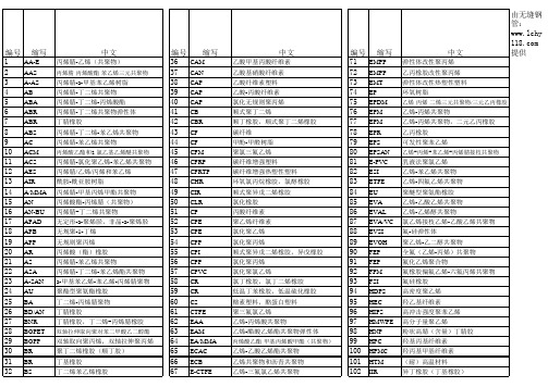
缩写
POM POR PP PPC PPE/PPO PP-R PPS PS PSAN PSB PSF/PSU PTFE PTT PU PVB PVC PVCA PVDC PVDF PVF SAB SAN SAN SB SBS SBEB SEBS SEBS SES SI SIR SIS SKT 环氧丙烷橡胶 聚丙烯 氯化聚丙烯 聚苯醚 三型聚丙烯 聚苯硫醚 聚苯乙烯
PEC(CPE) 氯化聚乙烯
PET(PETP) 聚对苯二甲酸乙二醇 酯
编号 211 212 213 214 215 216 217 218 219 220 221 222 223 224 225 226 227 228 229 230 231 232 233 234 235 236 237 238 239 240 241 242 243 244 245
缩写
EMPP EMPP EMT EP EPDM EPM EPM EPR EPS EPSAN E-PVC ESI ETFE EU EVA EVAL EVA/VC EVSI EVOH FEP FEP FPM FSI HDPS HEC HIPS HMWPE HNP HPC HPMC HTM IIR IPB IR LCP
缩写
CAM CAN CAP CAP CAP CB CBR CF CF CFM CFRP CFRTP CHR CIR CLR CP CPE CPE CPP CPI CPP CPVC CR CR CS CTFE EAA EAM EA/MMA ECAC ECB E-CTFE EHMWPE EMA
中文
乙酸甲基丙酸纤维素 乙酸基硝酸纤维素 乙酸纤维素塑料 乙酸-丙酸纤维素 氯化无规则聚丙烯 顺式聚丁二烯 顺丁橡胶,顺式聚丁二烯橡胶 碳纤维 甲酚-甲醛树脂 聚氯三氟乙烯 碳纤维增强塑料 碳纤维增强热塑性塑料 环氧氯丙烷橡胶,氯醇橡胶 顺式聚异戊二烯橡胶 氯化橡胶 丙酸纤维素 聚乙烯纤维素 氯化聚乙烯 氯化聚丙烯 顺式聚异戊二烯橡胶,异戊橡胶 氯化聚丙烯 氯化聚氯乙烯 氯丁橡胶,氯丁二烯橡胶 低温丁苯橡胶,低温硫化橡胶 酪素塑料,酪蛋白塑料 聚三氟氯乙烯 乙烯-丙烯酸共聚物 乙烯-醋酸乙烯酯共聚物弹性体
ACS标准应用程序参数表

实际信号和参数
概述
本章介绍了各种实际信号和参数,并给出每一个信号 / 参数的现场总线的对应值。附 加数据在附加:实际信号和参数一章中给出。
术语和缩略语
术语 最大绝对频率
最大绝对速度
实际信号 FbEq
参数
定义
参数 20.08 的值 , 或如果最小极限的绝对值大于最大极限则参数 20.07 的 值为绝对最大频率。
经积分和整形的 速度给定值。 100% 为电机的最大绝对速度。
20000 = 100%
02.09 TORQ REF 2
速度控制器输出。100% 为电机额定转矩。
0 = 0% 10000 = 100% 电机 额定转矩
02.10 TORQ REF 3
转矩给定值。100% 为电机额定转矩。
10000 = 100%
02.18 SPEED MEASURED
电机的实际测量速度 ( 未使用编码器时值为 0)。100% 为电机最大绝对 20000 = 100% 速度。
02.19 MOTOR ACCELERATIO 通过 01.02 MOTOR SPEED 计算电机加速度。
1=1 rpm/s.
02.20 USER CURRENT
一个 16 位的数据字。详细内容,请参见 《主 / 从机应用指南 (3ABD 00009807 [ 中文 ])》。
03.13 AUX STATUS WORD 3 一个 16 位的数据字。详细内容,请参见 214 页 “辅助状态字 3”部 分。
03.14 AUX STATUS WORD 4 一个 16 位的数据字。详细内容,请参见 214 页 “辅助状态字 4”部 分。
-20000 = 100% 电机最 大绝对速度
ACS 产品介绍
中压传动市场拓扑结构
© ABB Switzerland Ltd 03 / 2003
IGCT技术 不同拓扑结构和不同半导体元器件的系统所需的元器件数量
0 12 24 30 36 50
60
多电平LV IGBT
三电平HV IGBT
两电平SGCT
三电平 IGCT
元器件数量越少 => 可靠性越高
ABB
IGCT技术
IGCT技术
¾ 高可靠性
¾ IGCT的故障率指标FIT = 100 ¾ 交流耐压: 最高 6kV ¾ 直流耐压: 最高 3.9kV ¾ 通态电流: 2200 A ¾ 最少的功率半导体元器件的数量(12 Inv. IGCTs + 2 Pro. IGCT) ¾ 理论计算的MTBF = 50,000H
¾ 抑制谐波
保护不必要的系统的损害 放置在整流器和直流电容之间的保护IGCT–保护速度比普通熔断器快100倍 熔断器---易老化,不可靠,价格昂贵
ABB
适用于新电机或已有电机
输出正弦波滤波器
动态控制低通LC滤波器 消除所有的由逆变器开关带给电机的谐波 消除电机和轴承上共模电压的影响
DTC技术
DTC控制精度
Static speed error Dynamic speed error
PWM
no encoder
± 1 to 3 % 3 %sec.
PWM
with encoder
± 0.01 % 0.3 %sec.
DC drive
with encoder
± 0.01 % 0.3 %sec.
正弦波输出滤波器
ABB
© ABB Switzerland Ltd 03 / 2003
L9942中文大数据手册簿

实用文档特点■两路全桥,最大输出电流. 1.3 A(R DSON = 500 mΩ)■带查表功能的可编程驱动电流曲线表格: 9 级5位精度■内置PWM电流调整器和电流传感器■可编程的步进模式:全步、半步、细步、微步■可编程摆率控制:改善EMC性能降低功耗■可编程的高速-, 低速-,混合- 和自动衰减模式■ 3位精度的全范围可编程电流■可编程堵转检测■降低对微处理器要求的步进时钟输入■待机模式下功耗很低IS < 3 μA, typ. Tj ≤85 °C■所有输出均带:短路保护,负载开路,过载,温度预警和热关断功能■内部PWM控制器的PWM信号可以当做数据输出使用。
.■在下列工作范围内所有指标都会保证3 V < Vcc <5.3 V and for 7 V < Vs < 20 V用途双极步进电机驱动器在汽车上的应用:如灯光的水平控制,灯光方向调整,节气门控制。
描述L9942是一款集成的双极步进电机驱动器,具有细分模式和可编程电流配置表,能灵活适应步进电机的特性和预期的工作情况。
可以根据目标情况选用不同的电流配置表:噪音,振动,转速或者转矩。
衰减模式用在PWM-电流控制电路中,可以编程设置成低速-,高速-,混合-和自动衰减模式。
在自动衰减模式下,如果下一步电流是增加的,器件会采用低速模式,如果下一步电流是衰减的,则会采用高速或者混合模式。
可编程堵转检测在前灯水平调整和弯道调整应用中非常有用,可以防止堵转时电机为了转到位置而长时间的运行。
如果检测到堵转,对准过程被关闭,并且噪声被最小化。
表1 器件概要2009年5月文档编号11778 Rev6目录1 框图与引脚 . . . . . . . . . . . . . . . . . . . . . . . . . . . . . . . . . . . . . . . . . . . . . . . . . . . . . . . . . . . . 62 器件描述 . . . . . . . . . . . . . . . . . . . . . . . . . . . . . . . . . . . . . . . . . . . . . . . . . . . . . . . . . . . . . . 92.3 诊断功能 . . . . . . . . . . . . . . . . . . . . . . . . . . . . . . . . . . . . . . . . . . . . . . . . . . . . . . . . . . . . 9 2.4 过压与欠压检测 . . . . . . . . . . . . . . . . . . . . . . . . . . . . . . . . . . . . . . . . . . . . . . . . . . . . . . 9 2.5 温度报警与热关断 . . . . . . . . . . . . . . . . . . . . . . . . . . . . . . . . . . . . . . . . . . . . . . . . . . . . 10 2.6 感性负载 . . . . . . . . . . . . . . . . . . . . . . . . . . . . . . . . . . . . . . . . . . . . . . . . . . . . . . . . . . 10 2.7 交叉电流保护 . . . . . . . . . . . . . . . . . . . . . . . . . . . . . . . . . . . . . . . . . . . . . . . . . . . . . . . 10 2.8 PWM 电流调整 . . . . . . . . . . . . . . . . . . . . . . . . . . . . . . . . . . . . . . . . . . . . . . . . . . . . . . 10 2.9 衰减模式 . . . . . . . . . . . . . . . . . . . . . . . . . . . . . . . . . . . . . . . . . . . . . . . . . . . . . . . . . . . 10 2.10 过流检测 . . . . . . . . . . . . . . . . . . . . . . . . . . . . . . . . . . . . . . . . . . . . . . . . . . . . . . . . . 11 2.11 负载开路检测 . . . . . . . . . . . . . . . . . . . . . . . . . . . . . . . . . . . . . . . . . . . . . . . . . . . . . . 11 2.12 步进模式 . . . . . . . . . . . . . . . . . . . . . . . . . . . . . . . . . . . . . . . . . . . . . . . . . . . . . . . . . . 112.13 衰减模式 . . . . . . . . . . . . . . . . . . . . . . . . . . . . . . . . . . . . . . . . . . . . . . . . . . . . . . . . . . 133 电气参数 . . . . . . . . . . . . . . . . . . . . . . . . . . . . . . . . . . . . . . . . . . . . . . . . . . . . . . . . . . . . 14 3.1 绝对最大额定值 . . . . . . . . . . . . . . . . . . . . . . . . . . . . . . . . . . . . . . . . . . . . . . . . . . . . . 14 3.2 ESD 静电保护 . . . . . . . . . . . . . . . . . . . . . . . . . . . . . . . . . . . . . . . . . . . . . . . . . . . . . . 14 3.3 热参数 . . . . . . . . . . . . . . . . . . . . . . . . . . . . . . . . . . . . . . . . . . . . . . . . . . . . . . . . . . . . . 15 3.4 电气特性 . . . . . . . . . . . . . . . . . . . . . . . . . . . . . . . . . . . . . . . . . . . . . . . . . . . . . . . . . . . 16 3.4.1 电源 . . . . . . . . . . . . . . . . . . . . . . . . . . . . . . . . . . . . . . . . . . . . . . . . . . . . . . . . . . . . . 16 3.4.2 过压和欠压检测 . . . . . . . . . . . . . . . . . . . . . . . . . . . . . . . . . . . . . . . . . . . . . . . . . . . . 17 3.4.3 参考电流输出 . . . . . . . . . . . . . . . . . . . . . . . . . . . . . . . . . . . . . . . . . . . . . . . . . . . . . . 17 3.4.4 电荷泵输出 . . . . . . . . . . . . . . . . . . . . . . . . . . . . . . . . . . . . . . . . . . . . . . . . . . . . . . . 18 3.4.5 输出: Qxn (x = A; B n = 1; 2) . . . . . . . . . . . . . . . . . . . . . . . . . . . . . . . . . . . . . . . . . . 183.4.6 PWM 控制 . . . . . . . . . . . . . . . . . . . . . . . . . . . . . . . . . . . . . . . . . . . . . . . . . . . . . . . . 204 SPI的逻辑功能描述 . . . . . . . . . . . . . . . . . . . . . . . . . . . . . . . . . . . . . . . . . . . . . . . . . . . . 21 4.1 电机步进时钟输入 (STEP) . . . . . . . . . . . . . . . . . . . . . . . . . . . . . . . . . . . . . . . . . . . . . 21 4.2 PWM 输出 (PWM) . . . . . . . . . . . . . . . . . . . . . . . . . . . . . . . . . . . . . . . . . . . . . . . . . . . 21 4.3 串行外设接口 (SPI) . . . . . . . . . . . . . . . . . . . . . . . . . . . . . . . . . . . . . . . . . . . . . . . . . . 214.4 芯片反相片选 (CSN) . . . . . . . . . . . . . . . . . . . . . . . . . . . . . . . . . . . . . . . . . . . . . . . . 21 4.5 串行数据输入 (DI) . . . . . . . . . . . . . . . . . . . . . . . . . . . . . . . . . . . . . . . . . . . . . . . . . . 21 4.6 串行数据输出 (DO) . . . . . . . . . . . . . . . . . . . . . . . . . . . . . . . . . . . . . . . . . . . . . . . . . 22 4.7 串行时钟 (CLK) . . . . . . . . . . . . . . . . . . . . . . . . . . . . . . . . . . . . . . . . . . . . . . . . . . . . 224.8 数据寄存器 . . . . . . . . . . . . . . . . . . . . . . . . . . . . . . . . . . . . . . . . . . . . . . . . . . . . . . . 225 SPI –控制和状态寄存器 . . . . . . . . . . . . . . . . . . . . . . . . . . . . . . . . . . . . . . . . . . . . . . . 235.3 寄存器 2 . . . . . . . . . . . . . . . . . . . . . . . . . . . . . . . . . . . . . . . . . . . . . . . . . . . . . . . . . 24 5.4 寄存器 3 . . . . . . . . . . . . . . . . . . . . . . . . . . . . . . . . . . . . . . . . . . . . . . . . . . . . . . . . . 25 5.5 寄存器 4 和 5 . . . . . . . . . . . . . . . . . . . . . . . . . . . . . . . . . . . . . . . . . . . . . . . . . . . . . 25 5.6 寄存器 6 . . . . . . . . . . . . . . . . . . . . . . . . . . . . . . . . . . . . . . . . . . . . . . . . . . . . . . . . . 26 5.7 寄存器 7 . . . . . . . . . . . . . . . . . . . . . . . . . . . . . . . . . . . . . . . . . . . . . . . . . . . . . . . . . 26 5.8 辅助逻辑模块 . . . . . . . . . . . . . . . . . . . . . . . . . . . . . . . . . . . . . . . . . . . . . . . . . . . . . 27 5.8.1 故障条件 . . . . . . . . . . . . . . . . . . . . . . . . . . . . . . . . . . . . . . . . . . . . . . . . . . . . . . . . 27 5.8.2 SPI 通讯监视 . . . . . . . . . . . . . . . . . . . . . . . . . . . . . . . . . . . . . . . . . . . . . . . . . . . . 275.8.3 用于堵转检测的PWM 监视 . . . . . . . . . . . . . . . . . . . . . . . . . . . . . . . . . . . . . . . . . 276 SPI 逻辑的电气特性 . . . . . . . . . . . . . . . . . . . . . . . . . . . . . . . . . . . . . . . . . . . . . . . . 28 6.1 输入: CSN, CLK, STEP, EN 和 DI . . . . . . . . . . . . . . . . . . . . . . . . . . . . . . . . . . . . . 28 6.2 DI 的时序 . . . . . . . . . . . . . . . . . . . . . . . . . . . . . . . . . . . . . . . . . . . . . . . . . . . . . . . . 28 6.3 输出: DO, PWM . . . . . . . . . . . . . . . . . . . . . . . . . . . . . . . . . . . . . . . . . . . . . . . . . . . 29 6.4 输出: DO 的时序 . . . . . . . . . . . . . . . . . . . . . . . . . . . . . . . . . . . . . . . . . . . . . . . . . . . 29 6.5 CSN 的时序 . . . . . . . . . . . . . . . . . . . . . . . . . . . . . . . . . . . . . . . . . . . . . . . . . . . . . . 296.6 STEP 的时序 . . . . . . . . . . . . . . . . . . . . . . . . . . . . . . . . . . . . . . . . . . . . . . . . . . . . . 307 附录 . . . . . . . . . . . . . . . . . . . . . . . . . . . . . . . . . . . . . . . . . . . . . . . . . . . . . . . . . . . . . 337.1 堵转检测 . . . . . . . . . . . . . . . . . . . . . . . . . . . . . . . . . . . . . . . . . . . . . . . . . . . . . . . . 337.2 步进时钟输入 . . . . . . . . . . . . . . . . . . . . . . . . . . . . . . . . . . . . . . . . . . . . . . . . . . . . . 337.3 负载电流控制和过流检测(输出短路) . . . . . . . . . . . . . . . . . . . . . . . . . . . . . . . . . 338 包装信息 . . . . . . . . . . . . . . . . . . . . . . . . . . . . . . . . . . . . . . . . . . . . . . . . . . . . . . . . 389 历史版本 . . . . . . . . . . . . . . . . . . . . . . . . . . . . . . . . . . . . . . . . . . . . . . . . . . . . . . . . . 39表格列表表 1. 器件概要 . . . . . . . . . . . . . . . . . . . . . . . . . . . . . . . . . . . . . . . . . . . . . . . . . . . . . . . . . . 1 表 2. 引脚描述 . . . . . . . . . . . . . . . . . . . . . . . . . . . . . . . . . . . . . . . . . . . . . . . . . . . . . . . . . . 7 表 3. 真值表 . . . . . . . . . . . . . . . . . . . . . . . . . . . . . . . . . . . . . . . . . . . . . . . . . . . . . . . . . . . . 11 表 4. 绝对最大额定值 . . . . . . . . . . . . . . . . . . . . . . . . . . . . . . . . . . . . . . . . . . . . . . . . . . . . . 14 表 5. ESD 静电保护 . . . . . . . . . . . . . . . . . . . . . . . . . . . . . . . . . . . . . . . . . . . . . . . . . . . . . . 14 表 6. 工作时的结温 . . . . . . . . . . . . . . . . . . . . . . . . . . . . . . . . . . . . . . . . . . . . . . . . . . . . . . . 15表 9. 过压和欠压检测 . . . . . . . . . . . . . . . . . . . . . . . . . . . . . . . . . . . . . . . . . . . . . . . . . . . . . 17 表 10. 参考电流输出 . . . . . . . . . . . . . . . . . . . . . . . . . . . . . . . . . . . . . . . . . . . . . . . . . . . . . . 17 表 11. 电荷泵输出 . . . . . . . . . . . . . . . . . . . . . . . . . . . . . . . . . . . . . . . . . . . . . . . . . . . . . . . . 18 表 12. 输出: Qxn (x = A; B n =1; 2) . . . . . . . . . . . . . . . . . . . . . . . . . . . . . . . . . . . . . . . . . . 18 表 13. PWM 控制 (见图 4 和图 7). . . . . . . . . . . . . . . . . . . . . . . . . . . . . . . . . . . . . . . . . . . 20 表 14. 寄存器 0 . . . . . . . . . . . . . . . . . . . . . . . . . . . . . . . . . . . . . . . . . . . . . . . . . . . . . . . . . . 23 表 15. 寄存器 1 . . . . . . . . . . . . . . . . . . . . . . . . . . . . . . . . . . . . . . . . . . . . . . . . . . . . . . . . . . 24 表 16. 寄存器 2 . . . . . . . . . . . . . . . . . . . . . . . . . . . . . . . . . . . . . . . . . . . . . . . . . . . . . . . . . . 24 表 17. 寄存器 3 . . . . . . . . . . . . . . . . . . . . . . . . . . . . . . . . . . . . . . . . . . . . . . . . . . . . . . . . . . 25 表 18. 寄存器 4 和 5 . . . . . . . . . . . . . . . . . . . . . . . . . . . . . . . . . . . . . . . . . . . . . . . . . . . . . . 25 表 19. 寄存器 6 . . . . . . . . . . . . . . . . . . . . . . . . . . . . . . . . . . . . . . . . . . . . . . . . . . . . . . . . . . 26 表 20. 寄存器 7 . . . . . . . . . . . . . . . . . . . . . . . . . . . . . . . . . . . . . . . . . . . . . . . . . . . . . . . . . . 26 表 21. 输入: CSN, CLK, STEP, EN and DI . . . . . . . . . . . . . . . . . . . . . . . . . . . . . . . . . . . . . 28 表 22. DI 的时序 (见图 11 和图 13) . . . . . . . . . . . . . . . . . . . . . . . . . . . . . . . . . . . . . . . . . . 28 表 23. 输出: DO, PWM . . . . . . . . . . . . . . . . . . . . . . . . . . . . . . . . . . . . . . . . . . . . . . . . . . . . 29 表 24. 输出: DO 的时序(见图 12 和图 13) . . . . . . . . . . . . . . . . . . . . . . . . . . . . . . . . . . . . . . 29 表 25. CSN 的时序 . . . . . . . . . . . . . . . . . . . . . . . . . . . . . . . . . . . . . . . . . . . . . . . . . . . . . . . 29 表 26. STEP 的时序 . . . . . . . . . . . . . . . . . . . . . . . . . . . . . . . . . . . . . . . . . . . . . . . . . . . . . . . 30 表 27. 文档历史版本 . . . . . . . . . . . . . . . . . . . . . . . . . . . . . . . . . . . . . . . . . . . . . . . . . . . . . . . 39插图列表图 1. 方框图. . . . . . . . . . . . . . . . . . . . . . . . . . . . . . . . . . . . . . . . . . . . . . . . . . . . . . . . . . . . 6图 2. 引脚图 (顶视) . . . . . . . . . . . . . . . . . . . . . . . . . . . . . . . . . . . . . . . . . . . . . . . . . . . . . . 6图 3. 步进模式 . . . . . . . . . . . . . . . . . . . . . . . . . . . . . . . . . . . . . . . . . . . . . . . . . . . . . . . . . 12图 4. 衰减模式 . . . . . . . . . . . . . . . . . . . . . . . . . . . . . . . . . . . . . . . . . . . . . . . . . . . . . . . . . 13图 5. 封装的热数据 . . . . . . . . . . . . . . . . . . . . . . . . . . . . . . . . . . . . . . . . . . . . . . . . . . . . . 15图 6. VS 监视 . . . . . . . . . . . . . . . . . . . . . . . . . . . . . . . . . . . . . . . . . . . . . . . . . . . . . . . . . . 17图 7. 设置负载电流限制的逻辑 . . . . . . . . . . . . . . . . . . . . . . . . . . . . . . . . . . . . . . . . . . . . . 19图 8. 最小切换时间 . . . . . . . . . . . . . . . . . . . . . . . . . . . . . . . . . . . . . . . . . . . . . . . . . . . . . . 20图 11. 输入时序 . . . . . . . . . . . . . . . . . . . . . . . . . . . . . . . . . . . . . . . . . . . . . . . . . . . . . . . . . 30 图 12. SPI - DO 有效的数据延迟时间和有效时间 . . . . . . . . . . . . . . . . . . . . . . . . . . . . . . . 31 图 13. DO 使能和禁止时间 . . . . . . . . . . . . . . . . . . . . . . . . . . . . . . . . . . . . . . . . . . . . . . . . 31 图 14. 状态位 0 的时序 (故障条件) . . . . . . . . . . . . . . . . . . . . . . . . . . . . . . . . . . . . . . . . . . 32 图 15. 堵转检测 . . . . . . . . . . . . . . . . . . . . . . . . . . . . . . . . . . . . . . . . . . . . . . . . . . . . . . . . . 35 图 16. PWM 控制的参考产生 (接通) . . . . . . . . . . . . . . . . . . . . . . . . . . . . . . . . . . . . . . . . . 36 图 17. PWM控制的参考产生 (衰减) . . . . . . . . . . . . . . . . . . . . . . . . . . . . . . . . . . . . . . . . . . 37 图 18. PowerSSO24 机械尺寸和包装规格 . . . . . . . . . . . . . . . . . . . . . . . . . . . . . . . . . . . . 381 框图与引脚图图 1. 框图图 2. 引脚图 (顶视)2 芯片描述2.1 双电源供电: VS 和 VCC电源引脚VS脚给半桥供电。
ABB手动电机启动器技术目录手册说明书
ContentsManual Motor Starter MS 1160-16 A, 16/50 kA (6)Manual Motor Starter MS 3250-25 A, 100 kA (8)Remote control unit RC 325for starter combination, 0-16 A, 50 kA (11)Busbar System smissline-S for plug inuntil 160 A, 50 kA (12)Manual Motor Starters MS 45x11-50 A, 25/50 kA (14)Manual Motor Starters MS 49x11-50 A, 25/50/100 kA (14)MO-magnetic only applicationsuntil 100 A, 25/50 kA (17)Technical data, dimensions, Short circuit switching tables (18)Examples, applications (32)Switching capabilities of ABB‘s manual motor startersManual motor starters from ABB properly switch motors ON and OFF and protect them in case of overload and short circuit.Thus, ABB‘s manual motor starter know-how increases the reliability and availability of applications thanks to the extremely quick short circuit cut-off in cases that could cause motor damage.ABB motor starter combinations constitute a reliable, cost-efficient solution for all your motor protection needs, for examples in:•General engineering and plants •Industries •Conveyor systems•Chemical industries including process engineering •Pharmaceutical industries•Automation of buildings, e. g. in air-conditionings •Environmental plants •Power stations•Fresh water and sewage plants •Machine toolsManual Motor Startersand Motor Starter Combinations0.16 A 25 A50 A100 A16 A Manual motor starters provide protection against:•Overload •Short circuit •Phase failure •UndervoltageFuseless protection saves costs and space and provides for quick reaction under short circuit condition, switching the motor off within 3 ms. It is therefore an easy to handle,cost effective protection solution.Manual Motor Starters from ABBABB offers a wide range of a manual motor starters providing highly efficient motor protection up to 100 A.The arc breaking capacity of the devices can reach up to 100 kA depending of the motor starter type used,without the necessity for any special upstream protection.Thanks to its design MS 116/325 are suitable for industrial applicatons as well as for domestic installations.The device-types MS 116/325 can be easily coordinated with the ABB MCB-system, which is used in installations for touch-proved enclosures and panels.MS 450 to MS 497 are your best choice for high power applications. These models are used to power up large motors up to 45 kW.Technical Data, OverviewMotorstarter type MS116MS 325MS 45x MS 49x I e /A 162550100I CS /kA 16/30/5050/10025/5025/50/100Tripping class 101010,2010,20Magnetic type only Disconnect Capability,ref. IEC 60947-1The types MS 325 have the lowest “energy let through”-values on the market in case of short circuits.This way cables and the wiring are also protected optimally, providing for even higher safety.Manual motor starters must be set to the rated motor demand. Higher current is needed at motor start-up.During the start-up period the manual motor starter will let the current go through and will not trip, following the pertaining international standards and curves for motor start and hold operation.MSx Tripping curvesMagnetic releaseNo thermal releaseapprox. 12 * I Factor x I T r i p p i n g t i m e m s e cMO-types1 1.52346810152030406080Multiple of the rated currentMS 116 with mini contactor B6MS 116Manual Motor Starter MS 116AccessoriesOrdering detailsHKF 1-11MS 116 with A-contactorDirect adapterS S T 11601S T O 23014M S 116m 3bM S 116m 2bS T O 18014Open design, enclosure IP 20, resistant to changeable climates. Quick fastening on mounting rails DIN EN 50 022, 35 mm without auxiliary switch.ቢ Not suitable for panel mountingPadlock + 2 keys + lock adapterS 0109B 91 + S K 0150B 91Manual Motor Starter MS 116AccessoriesOrdering detailsSwitch cubicle mounting kitPower infeed block S1-M1Power infeed block S1-M2Phase buses PS1-2-1Phase buses PS1-4-1Insulatingenclosure IP 55Insulatingenclosure IP 65Plastic enclosure IP 40S T O 21014S T O 22014S T O 19014S T O 20014S T O 28014G E H _u s e sS T O 2701462-00-bAccessoriesባ Is srewed directly onto the manual motor starterMS 325 withauxiliary contacts HKF-11 front mountingSST2899Manual Motor Starter MS 325 Ordering detailsMS 325SST1497SelectionOpen design, enclosure IP 20, resistant to changeable climates. Quick fastening on mounting rails DIN EN 50 022, 35.S S T 009 95 RS S T 290 92 RSKASHKS S T 016 97S S T 309 92 RS S T 032 95 RUA for power in feed at bottomUA for power in feed at top, AAHKFManual Motor Starters MS 325Accessories Ordering details63-0Retrofittable accessoriesThese parts can be procured in addition to the MS 325; they must be installed by the user.ቢ Not simultaneously with UA/UA and AA, not suitable for distributor installationባ Max. 1 piece in conjunction with SK. SK must be mounted on first position ቤ Pre-mating normally open contactsብ Can be used together with UAF (power infeed at top) for safety circuit with Emergency Stop button (further information available on request)ቦ Other voltages, in particular DC, on requestቧ In particular if used with socke busbar system smissline-S (see Page 13)ቨ Recommendation: Connection of external voltage via terminal support ASS S T 30992RPadlock + 2 keys + lock adapterS 0109B 91 + S K 0150B 91S S T 022 93 RS S T 021 93 RS ST 023 93 RS S T 024 93 RDirect adapterSwitch cubiclemounting kitManual Motor Starters MS 325Accessories Ordering detailsPower infeed block S3-M1Power infeed block S3-M2Phase buses PS3-2-1Phase buses PS3-4-1Insulatingenclosure IP 55Insulatingenclosure IP 65S T O 28014S T O 18014S T O 3201462-00AccessoriesManual Motor Starter MS 325 AccessoriesOrdering details, Technical dataRC 325 mounted at MS 325RC 32558-SST2-switchingoperationsI e MS 325SST3--Wiring diagramA2T1, T2, T3542214132153MS 325RC 325A1L1, L2, L3>Mechanical and electronicaltime life AC-3, 400 VRemote Control Unit RC 325The Remote Control Unit RC 325is suitablefor manual motor starters type MS 325 up to16 A.With RC 325 and MS 325 customers willreceive a complete, fully coordinated startercombination, type I and type II in only oneproduct.This combination doesn’t need a backupfuse for a short circuit protection up to 60 kAat 16 A. The combination is fully coordinatedand after a short circuit event no contactswill be welded.Users will achieve a high availability sincethe combination‘s functionality is fullyrestored after a short circuit.Moreover, the combination is compact andsaves space and costs in operation.)RC 325 and MS 325 together work as amanual motor starter/contactor combination.The control circuit must be connected toRC 325 which controls MS 325. To startoperation, the MS 325 has to be switchedto its “ON”-position. The RC 325 thencontrols the main contacts of the MS 325for switching a motor or another load. Inthe event of a short circuit the manualmotor starter will trip. For restarting MS 325must be switched to its “ON”-position again.(RC 325 acts on 1 NO and 1 NC contact.The NO contact may operate as lockingcontact and the NC-contact may be usedOrdering detailsባ If RC 325 is used - auxiliary devices as HKF, HK, SK, shunt-, undervoltage- release are not suitable at the same time.57-12Busbar system smissline-S for MS 325Manual Motor Starter for plug inSmissline-S is a powerful busbar system for the quick and easy in-stallation of manual motor starters type MS 325 up to 160 A.A user of this system not only will save time and wiring costs in elec-trical installations but will be rewarded with increased safety. This powerful system offers large advantages in a current range up to 160 A with a short circuit capacity of 50 kA.ABB offers smissline modules in various lengths that are ready-made for directly mounting the MS 325 according to a simple plug-in philosophy – an ideal solution for fast installations with high wiring safety.socketbusbar S S T 03797supply in center: max. 160 AS S T 40426Smisslin-S is a proven system which has been succesfully installed in numerous hospitals, as well as in office and commercial buildings,power plants, industrial installations or in production lines. Smissli-ne-S can be installed either horizontally or vertically.In no time at all components can be changed or replaced safely in operation – a huge advantage for a quick and efficient service.Thus the installation achieves a very high availability and safety.13Busbar system smissline-S for MS 325Manual Motor Starter for plug inS K 0120 B 93ZLS 100S K 0121 B93ZLS 101S K 0087 B 94ZLS 930S K 0119 B 93ZMS 915ZLS 756S S T 40277S K 0197 B 93ZLS 224/225S S T 40158ZLS 802Busbar module incl. sockets,busbars and end pieces14MS 495 with A95connected via BEA 110/495S S T 09498MS 495 with auxiliary switch HKS4-02 and open-circuit shunt release AA4 in addition to terminal shroud KA495CS T 14-02MS 49xS S T 01898MS 45xS S T 02198Manual Motor Starters MS 4xxOrdering detailsSelectionopen design. enclosure IP 20, resistant to changeable climates. Quick fastening on mounting rails DIN EN 50 022, 35 mm without auxiliary switch15S S T 09198Pilot switch SK4-11S S T 01599Manual Motor Starters MS 4xxAccessories Ordering detailsAuxiliary switch HK4-11Auxiliary switch HKS4-02S S T 08598Open-circuit shunt release AA4S S T 07798Undervoltage release UA4-HKS S T 8698Retrofittable accessoriesThese parts may be procured in addition to the MS 4xx.They must be mounted by the user.ቢIs plugged onto the box terminals in each case ብMounting sequence: Motor protection switch, pilot switch, auxiliary switch ባIs plugged onto the housing after removing ቦ Max. ON time: 5 seconds, see also Page 20the box terminals, if using cable lugs or buses ቧSee also MS325 Page 10ቤSupplied only as a set as 10 scale covers ቨIs screwed directly onto the manual motor starterStrategies for Motor protection with magnetic only types MOFor special applications ABB’s manual motor starterof the MS series are also available as versionsMO 325 / MO 450 / MO 495 with magnetic tripping only, protecting exclusively against short circuits.However, combined with intelligent ABB-components, the starter series MO open up further interesting alternatives for the use of motor starters, especially when short circuit protection and thermal protection have to be realized independent from one another.Therefore three different strategies of motor protection with manual motor starters MO from ABB are feasible: 1.With thermal overload relays:cost efficient protection against overload andphase failure2.With electronic overload relays:For high accuracy and efficient stock planing,less types for the complete range, highflexibility.3.Thermistor motor protectionwith electronic relays Custorapid®:High accuracy with temperature monitoringdirectly in the coil, highly efficient protectionwith several electronic posibilities.Examples for motor protectionup to 25 A up to 50 A up to 100 A1617Magnetic only types MO 4xx - circuit breakersOrdering detailsS S T 02198S S T 01898SelectionThe tripping curves show the tripping time dependend on the factor of the selected motor current. The values have a tolerances of approx. +/- 20%.Standard manual motor starters have thermal protection against overload, a magnetic protection against short circuit and a protection against phase failure.Types MOxx protect only against short circuit. The thermal release and phase failure are not in functon.Applications are:Short circuit protection against resistance loadsShort circuit protection using TOL for thermal protectonOnly short circuit protection for loads where a tripping curve 12 ...14 x In is requiredቤAlso applies to auxiliary switches HKF1 and undervoltage release UA1ብFor auxiliary switch HKF.. Pozidrive 2ቦApplies to auxiliary switches HK1 and SK1Manual Motor Starters Type Series MSTechnical dataSST1497SST2198SST1898SST116118Manual Motor Starters Type Series MSTechnical data19Manual Motor Starters Type Series MSTechnical dataቢCurrent ranges 0.16 to 0.63 AባCurrent ranges 1 to 2.5 AቤCurrent ranges 4 to 6.3 AብCurrent ranges 9 to 25 Aቦ24-60 V: 14.4-90 VA20Manual Motor Starters Type Series MSTechnical dataShort-circuit protection MS 116, setting ranges, short-circuit strength and max. back-up fusesMaximum rated current of the short-circuit fuses if I cc > I cs ቢቢI cs =Rated service short-circuit breaking capacity, I cu = Rated ultimate short-circuit capacity, I cc = Prospective short-circuit current at installation location.I cs =I cu in the case of MS 325 and MS 116!21Manual Motor Starters Type Series MSTechnical dataShort-circuit protection MS 450 / MS 451, setting ranges, short-circuit strength and max. back-up fusesቢ I cs = Rated service short-circuit breaking capacity, I cu = Rated ultimate short-circuit breaking capacity I cc = pProspective short-circuit current at installation location.Manual Motor Starters Type Series MSTechnical dataCoordination acc. IEC / EN 60947-4-1The following table lists the combinations of motor protection switches and contactors according to assignment type 2 in compliance with IEC / EN 60947-4-1Further coordination tables on requestForward current integrals (lt2 curves) on requestPeak forward current curves on requestReliable line protectionManual Motor Starters Type Series MSTechnical dataTimes to tripSelection table for suitability of the motor protection switches for motors of enclosure eTime to trip of the motor protection switches as a function of a multiple of the setting current (tolerance 20 % of the time to trip).PTB approvals, see below.Ident-numbersof manual motor starters for motors with EEx e-Protection:Type Ident-No.MS 325 3.53 - 1357/94National Institute for Standards and TechnologyMS 450, MS 495, MS 497Ex - 99.Y.74976KEMAApprovals and certificatesCSA GL LRS BV DNVCanada USA Germany Great Britain France Norway M M m mM Normal version approved: Rating plates bear the test mark if mandatory.m Submitted for approval, delivery time on request.13211422I >21I >43I >6507D108U <D2U <D1D212141157657785C1C2Manual motor starter MS 116 with accessories in accordance with the adjacent captionManual Motor Starters Type Series MSWiring diagramsManual motor starter MS 325 with accessories in accordance with the adjacent captionቪቫቢባቤManual motor starterfor switching direct current and single-phase alternating currentManual motor starter MS 4xxin accordance with the adjacent captionቢባManual Motor Starter MS 116AccessoriesDimension diagramsDimension in mm 17785,645HKF1-11BEA16/11615985,645BEA7/116B6 / B7HKF1-11Manual motor starter MS 116 mounted with contactor A9...A16Manual motor starter MS 116 mounted with mini contactor B6/7Manual Motor Starters MS 325AccessoriesDimension diagramsDrilling planDriver and spindlesT 216 98Mounting depth mm 90137157182Axial length mm3285105130S S T 105 92 MSwitch cubicle mounting kitS S T 214 98Outer twist knobsDrilling planS S T 201 99driveraxismounting depthHandledriverAxis 85...180 mmdriver spindle 32 mmDimension in mmManual Motor Starters MS 325AccessoriesDimension diagrams95Mounting platestarter combination for plug into busbar system smissline-SDimensions in mmwidthdepthh e i g h tt o t a l h e i g h tBusbar system smissline-SDimensions in mmS K 0251 Z 93Motor protection switch MS 325 3 PLE259 Z 93Auxiliary switch block HK with empty housing ZLS 9301 PLES S T 9003Auxiliary switch block HKS4Pilot swich SK4Open-circuit shunt release/undervoltage release AA4, UA4, UA4-HK Auxiliary switch HK4ÁTop-hat rail 35 mm to DIN EN 50022Top-hat rail 35 mm, 15 mm high to DIN EN 50022or Top-hat rail 75 mm to DIN EN 50023ÂSwitch knob lockable in zero position with bracket diameter 5 mmMotor manual starter MS 45xMotor manual starter MS 49xS S T 9004S S T 8193MS 45x with disconnector module TB 450Manual Motor Starters MS 45x / MS 49xDimension diagramsNotesManual Motor Starter MS 325Combinations with AccessoriesMS 325with undervoltage release UAFMS 325 with auxiliary switch HKcross-wired with phase buses and power infeed blockMS 116 cross wired via phase busses and power infeed blocks S S T 02597S T 01501QES 6/3 NMS 325 with RC 325 in PCD 6 NS S T 02297S T 01601Insulatingenclosure IP 65Manual Motor Starter MS 325Combinations with AccessoriesMS 325 + HK + SK withcompact reversing contactor VB 6MS 325 + HKF with contactor A 16S S T 09698MS 325 with contactor A 26on busbar adapter SA 11S T 02401S T 03201Insulating enclosure IP 65 with locksMS 495 with A95connected via BEA 110/495The new FBP (FieldBusPlug) product family is a communication device range of switching and automation components whichcan be combined easily with standard fieldbus systems.Manual Motor Starter Application: Switching on/off, Disconnection and locking for service, MotorprotectionRC 325 and MS 325 - this smart motor starter combination is quite an innovative solution for protecting and switching remotely,all in one single device, automatically coordinated up to 100 kA.It can be plugged into the manual motor starter MS 325 laterally.As an innovative and extremely compact motor starter combination it provides the designengineer with a powerful yet easy to use modulardevice for switching, protecting and remote controlling of a motor.Customer Benefits•Remote control for MS 325•Compact starter according to IEC 60947-4-1•No need for additional coordination,thanks to mechanical interlockTechnical data for the compact motor starter Operating current:up to 16 AShort circuit range:up to 100 kASwitching capacity:up to 1.000.000 operations Several control circuits RC 325are available in a wide voltage rangeCompact motor starterManual Motor Starter MS 325 and switching Unit RC 325Various Motor Starter combinationsThe manual motor starters from ABB are designed to be easily coordinated with various other components from ABB tors Series “B”.Such a modular philosophy brings endusers an emproved service and faster reactionsin operating systems.Various Motor Starter combinationsA unit MS 116/325 can be clipped,forming an automatically connected motor starter combination.Fast front connection, compactdimensions and a robust design are only the most obvious advantages of ABB’s motor starters.Seperate gear conceptIndividual devices for single wiring.Manual motor starter and contactor can be wired according to customer demands.•cost efficient•reliable•space-savingCustomer benefits:•fully coordinated modular assembly •easy planning •no wiring necessary •compact - space saving •easy to change•better and quicker service •FBP connection to field bussesDOL StartersModular conceptMotor starter Combinationswithout or with field bus connection.ABB STOTZ-KONTAKT GmbH P .O. Box 10168069006 Heidelberg GermanyPhone:+49 (0) 62 21 / 7 01-0Fax:+49 (0) 62 21 / 7 01-729Internet:www.abb.de/stotz-kontaktDevice type Approvals Ships’ classification societiesTest markAbbreviation CSA USAPTB GL LRSBV DNV Validity CanadaGermany Germany Great Britain France NorwayMS 116MS 325MS 45xMS 49xP u b l i c a t i o n N o .: 2C D C 130 002 C 0203 P r i n t e d i n t h e F e d e r a l R e p u b l i c o f G e r m a n y (10/03 · 5 · G V D )。
ACS400变频器用户手册(ABB)

控制方式 . . . . . . . . . . . . . . . . . . . . . . . . . . . . . . . . . . . . . . . . . . . . 35
输出显示 . . . . . . . . . . . . . . . . . . . . . . . . . . . . . . . . . . . . . . . . . . . . 36
过载能力 ACS 400
. . . . . . . . . . . . . . . . . . . . . . . . . . . . . . . . . . . . 25
型号和技术数据 . . . . . . . . . . . . . . . . . . . . . . . . . . . . . . . . . . . . . . 26
通电 . . . . . . . . . . . . . . . . . . . . . . . . . . . . . . . . . . . . . . . . . . . . . . . 23
环保要求. . . . . . . . . . . . . . . . . . . . . . . . . . . . . . . . . . . . . . . . . . . . 23
安装警告牌 . . . . . . . . . . . . . . . . . . . . . . . . . . . . . . . . . . . . . . . . . . . 9
铭牌标签. . . . . . . . . . . . . . . . . . . . . . . . . . . . . . . . . . . . . . . . . . . . 10
打开外壳. . . . . . . . . . . . . . . . . . . . . . . . . . . . . . . . . . . . . . . . . . . . . 7
- 1、下载文档前请自行甄别文档内容的完整性,平台不提供额外的编辑、内容补充、找答案等附加服务。
- 2、"仅部分预览"的文档,不可在线预览部分如存在完整性等问题,可反馈申请退款(可完整预览的文档不适用该条件!)。
- 3、如文档侵犯您的权益,请联系客服反馈,我们会尽快为您处理(人工客服工作时间:9:00-18:30)。
1November 1997ACS139MSRadiation HardenedDual 2-to-4 Line Decoder/DemultiplexerFeatures•QML Qualified Per MIL-PRF-38535 Requirements • 1.25Micron Radiation Hardened SOS CMOS•Radiation Environment-Latch-up Free Under any Conditions-Total Dose. . . . . . . . . . . . . . . . . . . . . .3 x 105RAD(Si)-SEU Immunity. . . . . . . . . . .<1 x 10⁻¹⁰ Errors/Bit/Day -SEU LET Threshold . . . . . . . . . . .>100MeV/(mg/cm 2)•Input Logic Levels . . .V IL = (0.3)(V CC ), V IH = (0.7)(V CC )•Output Current. . . . . . . . . . . . . . . . . . . . . . . . . . . .±8mA •Quiescent Supply Current. . . . . . . . . . . . . . . . . . .400µA •Propagation Delay-Enable to Output . . . . . . . . . . . . . . . . . . . . . . . . .13ns -Address to Output . . . . . . . . . . . . . . . . . . . . . . . .15nsApplications•Memory Decoding •Data Routing •Code conversionDescriptionThe Radiation Hardened ACS139MS contains two indepen-dent binary to one-of-four decoders, each with a single active low enable input. Data on the select inputs cause one of the four normally high outputs to go low.If the enable input is high, all four outputs remain high. During demultiplexer operation the enable input acts as the data input.The enable input also functions as a chip select when the devices are cascaded.The ACS139MS is fabricated on a CMOS Silicon on Sapphire (SOS) process, which provides an immunity to Single Event Latch-up and the capability of highly reliable performance in any radiation environment. These devices offer significant power reduction and faster performance when compared to ALSTTL types.Specifications for Rad Hard QML devices are controlled by the Defense Supply Center in Columbus (DSCC). The SMD numbers listed below must be used when ordering.Detailed Electrical Specifications for the ACS139 are contained in SMD 5962-97639. A “hot-link” is provided on our homepage with instructions for downloading./data/sm/index.htmOrdering InformationSMD PART NUMBER INTERSIL PART NUMBER TEMP. RANGE (o C)PACKAGE CASE OUTLINE 5962F9763901VEC ACS139DMSR-02-55 to 12516 Ld SBDIP CDIP2-T16N/AACS139D/Sample-022516 Ld SBDIP CDIP2-T165962F9763901VXC ACS139KMSR-02-55 to 12516 Ld Flatpack CDFP4-F16N/A ACS139K/Sample-022516 Ld Flatpack CDFP4-F16N/AACS139HMSR-0225DieN/APinoutsACS139 (SBDIP)TOP VIEWACS139 (FLATPACK)TOP VIEW141516913121110123457681E 1A01A11Y01Y11Y2GND 1Y3V CC 2A02A12Y02Y12Y22Y32E 1E 1A01A11Y01Y11Y21Y3GND23456781161514131211109V CC 2E 2A02A12Y02Y12Y22Y3File Number4431CAUTION: These devices are sensitive to electrostatic discharge; follow proper IC Handling Procedures. or 407-727-9207|Copyright © Intersil Corporation 1999Die CharacteristicsDIE DIMENSIONS:Size:2390µm x 2390µm (94 mils x 94 mils) Thickness:525µm±25µm (20.6 mils±1 mil) Bond Pad: 110µm x 110µm (4.3 mils x 4.3 mils) METALLIZATION:T ype:AlMetal 1 Thickness: 0.7µm±0.1µmMetal 2 Thickness: 1.0µm±0.1µm SUBSTRATE:Silicon on Sapphire (SOS)SUBSTRATE POTENTIAL:Unbiased InsulatorBACKSIDE FINISH:SapphirePASSIVATIONType: Phosphorous Silicon Glass (PSG) Thickness: 1.30µm±0.15µmSPECIAL INSTRUCTIONS:Bond V CC FirstADDITIONAL INFORMATION:Worst Case Density:<2.0 x 10⁵ A/cm2 Transistor Count:190Metallization Mask LayoutACS139MS.1A01E V CC2E1A1 1Y0 1Y1 1Y22A02A12Y02Y1 1Y3GND2Y32Y2ACS139MSAll Intersil semiconductor products are manufactured, assembled and tested under ISO9000 quality systems certification. Intersil products are sold by description only. Intersil Corporation reserves the right to make changes in circuit design and/or specifications at any time without notice. Accordingly, the reader is cautioned to verify that data sheets are current before placing orders. Information furnished by Intersil is believed to be accurate and reliable. However, no responsibility is assumed by Intersil or its subsidiaries for its use; nor for any infringements of patents or other rights of third parties which may result from its use. No license is granted by implication or otherwise under any patent or patent rights of Intersil or its subsidiaries.For information regarding Intersil Corporation and its products, see web site 2。