锐捷20系列接入交换机
锐捷交换机交换机配置

锐捷交换机交换机配置锐捷交换机交换机配置安全ACL1.配置ACLs 的步骤l 通过申明一个ACL 的名字及为该ACL 创建ACEs(每条ACE 均由匹配条件和行为构成)来创建一条ACL。
l 将该ACL 应用于某一个交换机接口。
2.Standard (标准) 或Extended(扩展)IP ACLs步骤1 configure terminal 进入全局配置模式。
步骤2 ip access-list standard { name}用数字或名字来定义一条StandardIP ACL 并进入access-list 配置模式。
步骤3 deny {source source-wildcard|host source|any} or permit {source source-wildcard|host source|any}[time-range time-range-name]在特权配置模式,您可以通过如下步骤来创建一条Standard IP ACL在access-list 配置模式,申明一个或多个的允许通过(permit)或丢弃(deny)的条件以用于交换机决定报文是转发或还是丢弃。
host source 代表一台源主机,其source-wildcard 为0.0.0.0。
any 代表任意主机,即source为0.0.0.0,source-wild 为255.255.255.255。
time-range-name(可选)指明关联的time-range 的名称步骤4 end退回到特权模式。
步骤5 show access-lists [name]显示该接入控制列表,如果您不指定access-list 及name 参数,则显示所有接入控制列表。
步骤6 copy running-config startup-config保存配置例:创建一条IP Standard Access-list(标准访问列表)该ACL 名字deny-host192.168.l2.x:包含两条ACE:第一条ACE 拒绝来自192.168.12.0 网段的任一主机,第二条ACE 允许其它任意主机。
锐捷ACL应用技术白皮书 锐捷网络 网络解决方案第一品牌公司

锐捷ACL应用技术白皮书摘要ACL,是访问控制列表(Access Control Lists)的简称。
在实际的网络环境中,各种上层访问都是通过报文交互进行的,为了进行访问控制,就通过ACL设置一系列过滤规则来控制报文转发和过滤,从而达到目的,所以称之为访问控制列表。
本文阐析了ACL功能的工作机制。
并在此基础上,说明我司交换机在ACL功能上的特点,优越性及其应用。
关键词ACL ACE目录摘要 (1)关键词 (1)1 缩略语 (2)2 概述 (2)2.1 ACL技术产生的背景 (2)2.2 我司交换机产品对ACL功能的支持情况 (3)3 技术介绍 (4)3.1 ACL工作原理 (4)3.1.1 ACL分类 (4)3.1.2 安全ACL种类 (4)3.1.3 Access Control Entry (4)3.1.4 安全ACL过滤报文原理 (6)3.1.5 基于接口和基于VLAN的ACL (8)4 锐捷ACL技术特点 (11)4.1 配置灵活方便 (11)4.2 功能完备 (11)4.3 过滤性能好 (11)4.4 各款产品ACL功能限制 (12)4.4.1 各类型ACL共有限制 (12)4.4.2 各款产品支持情况差异性说明 (12)4.4.3 机箱式设备的线卡类型汇总 (14)4.5 各款产品ACL在各种应用情况下的限制和容量值 (15)4.5.1 IP标准ACL的限制和容量值 (15)4.5.2 IP扩展ACL的限制和容量值 (15)4.5.3 MAC扩展ACL的限制和容量值 (16)4.5.4 专家级ACL的限制和容量值 (17)4.5.5 IPv6 ACL的限制和容量值 (17)4.6 使用我司ACL功能注意事项 (18)4.7 应用与案例分析 (19)4.7.1 核心层交换机S86关键配置 (20)4.7.2 汇聚层交换机S57关键配置 (22)4.7.3 接入层交换机S26关键配置 (24)5 结束语 (26)1 缩略语ACL:Access Control List,访问控制列表ACE:Access Control Entry,ACL的组成元素VACL:基于VLAN的ACLPort ACL:基于二层接口的ACLAP:Aggregate PortL2 AP:二层AP接口L3 AP:三层AP接口SVI:Switch Vlan Interface,交换机虚拟VLAN接口Routed Port:路由口2 概述2.1 ACL技术产生的背景在实际网络环境中,各种上层访问,最常见的就是访问某个网站,归根结底是通过PC和服务器之间的报文交互进行的,而报文则是通过交换机,路由器等各种网络设备进行传输的。
锐捷交换机路由器配置教程
目录第一章:设备配置和文件管理 (4)1.1 通过TELNET 方式来配置设备 (4)1.2 更改IOS 命令的特权等级 (4)1.3 设备时钟设置 (5)第二章:交换机基础配置 (5)2.1 交换机vlan 和trunk 的置 (5)2.2 turnk 接口修剪配置 (6)2.3 PVLAN 配置 (7)2.4 端口汇聚配置 (8)2.5 生成树配置 (9)2.6 端口镜像配置 (9)第三章:交换机防止ARP 欺骗置 (10)3.1 交换机地址绑定(address-bind )功能 (10)3.2 交换机端口安全功能 (10)3.3 交换机arp-check 功能 (11)3.4 交换机ARP动态检测功能(DAI) (11)第四章:访问控制列表配置(ACL) (12)4.1 标准ACL配置 (12)4.2 扩展ACL配置 (13)4.3 VLAN之间的ACL配置 (13)4.4 单向ACL的配置 (15)第五章:应用协议配置 (16)5.1 DHCP服务配置 (16)5.2 交换机dot1x认证配置 (18)5.3 QOS限速配置 (19)5.4 IPsec配置 (20)5.5 GRE配置 (22)5.6 PPTP 配置 (22)5.7 路由器L2TP配置 (23)5.8 路由器NAT 配置 (24)第六章:路由协议配置 (25)6.1 默认路由配置 (25)6.2 静态路由配置 (25)6.3 浮动路由配置 (25)6.4 策略路由配置 (25)6.5 OSPF 配置 (26)6.6 OSPF 中router ID 配置 (27)第一章:设备配置和文件管理1.1 通过TELNET 方式来配置设备提问:如何通过telnet 方式来配置设备?回答:步骤一:配置VLAN1 的IP 地址S5750>en ---- 进入特权模式S5750#conf ---- 进入全局配置模式S5750(config)#int vlan 1 ---- 进入vlan 1 接口S5750(config-if)#ip address 192.168.0.230 255.255.255.0---- 为vlan 1 接口上设置管理ipS5750(config-if)#exit ----退回到全局配置模式步骤二:配置telnet密码S5750(config)#line vty 0 4 ----进入telnet密码配置模式S5750(config-line)#login ---启用需输入密码才能telnet 成功S5750(config-line)#password rscstar ----将telnet密码设置为rscstarS5750(config-line)#exit ----回到全局配置模式S5750(config)#enable secret 0 rscstar----配置进入特权模式的密码为rscstar步骤三:开启SSH服务(可选操作)S5750(config)#enable service ssh-server ---开启ssh服务S5750(config)#ip ssh version 2 ----启用ssh version 2S5750(config)#exit ---- 回到特权模式S5750#wri ----保存配置1.2 更改IOS 命令的特权等级提问:如何只允许dixy这个用户使用与ARP相关的命令?回答:S5750(config)#username dixy password dixy ---- 设置dixy 用户名和密码S5750(config)#username dixy privilege 10 ----dixy 帐户的权限为10S5750(config)#privilege exec level 10 show arp---- 权限10 可以使用show arp 命令S5750(config)#privilege config all level 10 arp---- 权限10 可以使用所有arp 打头的命令S5750(config)#line vty 0 4 ---- 配置telnet 登陆用户S5750(config-line)#no passwordS5750(config-line)#login local注释:15 级密码为enable 特权密码,无法更改,0 级密码只能支持disable ,enable ,exit和help , 1 级密码无法进行配置。
锐捷系列交换机常用配置的命令
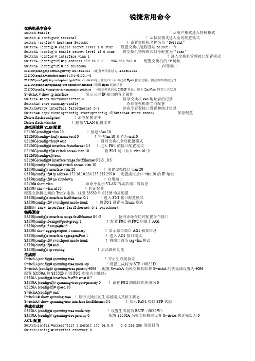
锐捷常用命令交换机基本命令switch>enable !从用户模式进入特权模式switch # configure terminal !从特权模式进入全局配置模式switch (config)# hostname SwitchA !设置交换机名称为为“SwitchA”SwitchA (config)# enable secret level 1 0 star 设置交换机远程登陆telnet口令SwitchA (config)# enable secret level 15 0 star 将交换机特权模式口令配置为“star”SwitchA (config)# interface vlan 1 !进入交换机管理接口配置模式SwitchA (config-if)#ip address 172.16.0.1 255.255.255.0 配置交换机的IP地址SwitchA (config-if)# no shutdown ! 启用端口S2150G(config)#ip default-gateway 192.168.1.254 //配置网关地址为192.168.1.254S2150G(config)#interface range f 1/0/1-48,2/0/1-48S2150G(config-if) #spanning-tree bpdufilter enabled//将上联光纤口启动过滤Bpdu报文功能,提高网络的稳定性S2150G(config-if)#spanning-tree bpdufilter disabled //禁用Bpdu过滤功能S2150G(config) #snmp-server community public ro //给交换机启动SNMP协议,便于StarView网管工具发现SwitchA # show ip interface 显示三层IP接口的各个属性SwitchA #show mac-address-table 显示交换机MAC地址表的记录SwitchA# show running-config 查看交换机的当前配置SwitchA#show interface fastethernet 0/1 该命令查看接口设置和统计信息SwitchA# copy running-config startup-config 或SwitchA# write memory 保存配置Delete flash:config.text !清除配置文件Delete flash:vlan.dat !删除VLAN配置文件虚拟局域网VLAN配置S2126G(config)# vlan 10 !创建vlan 10S2126G(config-vlan)# name test10 !将Vlan 10命名为test10S2126G(config-vlan)# exit !返回交换机全局配置模式S2126G(config)# interface fastethernet 0/1 !进入F0/1的接口配置模式S2126G(config-if)# switch access vlan 10 !将F0/1端口加入vlan 10中S2126G(config-if)#exitS2126G(config)# interface range fastEthernet 0/2-3 , 0/5S3550(config-if-range)# switch access vlan 10S3550(config)# interface vlan 20 ! 创建虚拟接口vlan 20S3550(config-if)# ip address 172.16.10.254 255.255.255.0 配置虚拟接口vlan 20的IP地址S3550(config-if)# no shutdown !启用端口S2126# show vlan !该命令显示VLAN的成员端口等信息S3550# show vlan id 10 !验证配置配置交换机之间的Trunk连接:注意S3550和S2126均需配置S3550(config)# interface fastEthernet 0/1 !进入F0/1接口配置模式S3550(config-if)# switchport mode trunk !将F0/1设置为Trunk模式S3550# show interface fastEthernet 0/1 switchport链路聚合S3550(config)# interface range fastEthernet 0/1-2 !使用该命令同时配置多个接口S3550(config-if-range)#port-group 1 !配置F0/1和F0/2归属于AG1S3550(config-if-range)#endS3550# show aggregateport 1 summary !显示聚合端口AG1摘要信息S3550(config)# interface aggregatePort 1 !进入AG1接口模式S3550(config-if)# switchport mode trunk !将端口设为tag vlan模式S3550(config-if)# endS3550(config)# ip routing !启动路由功能生成树SwitchA(config)# spanning-tree ! 开启生成树协议SwitchA(config)# spanning-tree mode stp ! 设置生成树为STP(802.1D)SwitchA (config)# spanning-tree priority 4096 配置SwitchA为根交换机即将SwitchA的优先级设置为4096配置S3550A和S3550B间的F0/2连接为主链路:S3550A (config)# interface fastEthernet 0/2S3550A (config-if)# spanning-tree port-priority 0 !设置F0/2的端口优先级为0S2126A (config-if)# speed 10SwitchA(config)# endSwitchA# show spanning-tree !显示交换机的生成树模式及相关状态SwitchA# show spanning-tree interface fastEthernet 0/1 ! 显示Fa0/1接口STP状态快速生成树S3550A (config)# spanning-tree mode rstp ! 设置生成树为RSTP(802.1W)S3550A (config)# spanning-tree priority 0 配置S3550A为根交换机即设置SwitchA的优先级为0ACL配置Switch(config)#access-list 1 permit 172.16.0.0 0.0.255.255 靠近目的Switch(config)#interface ethernet 0Switch(config-if)#ip access-group 1 outSwitch(config)#access-list 101 deny tcp 192.168.1.0 0.0.0.255 host 192.168.10.100 eq 80Switch(config)#access-list 101 permit ip any anySwitch(config)#interface ethernet 1Switch(config-if)#ip access-group 101 outSwitch # show access-list 显示所有的ACLSwitch # show ip access-lists 1 显示IP ACL1Switch # show ip interface fastEthernet 1/1 显示f1/1接口的访问列表静态路由格式:router(config)# ip route [未直连的目的网段] [子网掩码] [转发路由器的IP地址/本地接口R1(config)# ip route 172.16.2.0 255.255.255.0 172.16.21.2 !配置静态路由R1# show ip route !查看路由表缺省路由:ip route 0.0.0.0 0.0.0.0 [转发路由器的IP地址/本地接口RIP协议R1(config)# router rip !启用RIP进程R1(config-router)# network 172.16.1.0 !公布直连网络R1(config-router)# network 172.16.21.0 !公布直连网络router# show ip protocols !验证RIP的配置R1# show ip interface brief !显示接口的摘要信息router# debug ip rip !在控制台显示RIP的工作状态PPP协议R1(config)# interface serial 1/2R1(config-if)# ip address 172.16.10.1 255.255.255.0R1(config-if)# encapsulation ppp !配置接口封装为PPP;两端均需配置R1(config-if)# no shutdownR1(config-if)# clock rate 64000NAT让内部主机在公网地址缺乏的情况下可以访问外部网络(主要命令)R1(config)# ip route 0.0.0.0 0.0.0.0 serial 1/2 先做缺省路由R1(config-if)#ip nat inside 进入F0/1,定义为内网接口R1(config-if)#ip nat outside 进入S1/2,定义为外网接口R1(config)#ip nat pool internet 200.1.8.7 200.2.8.7 netmask 255.255.255.0 定义内部全局地址池R1(config)#access-list 10 permit 172.16.1.0 0.0.0.255 定义允许转换的地址R1(config)#ip nat inside source list 10 pool internet overload 为内部本地调用转换地址池NAT发布主机R1(config)# ip route 0.0.0.0 0.0.0.0 serial 1/2 先做缺省路由R1(config)#int fa0/1R1(config-if)#ip nat insideR1(config-if)#exitR1(config)#int s1/2R1(config-if)#ip nat outsideR1(config-if)#exitR1(config)#ip nat pool webserver 172.16.8.5 172.16.8.5 netmask 255.255.255.0 定义内网服务器地址池R1(config)#access-list 3 permit host 200.1.8.7 定义外网的公网IPR1(config)#ip nat inside destination list 3 pool webserver 将外网的公网IP地址转换为web服务器地址R1(config)#ip nat inside source static tcp 172.16.8.5 80 200.1.8.7 80 定义访问外网IP的80端口时转换为内网的服务器IP 的80端口。
交换机功能概述(核心和接入)(1)

交换机功能概述(核心和接入)(1)1.1.1.1 锐捷核心交换机产品概述RG-S5750-H系列交换机是锐捷网络新推出的高性能、强安全、集成多业务的新一代以太网交换机,该系列交换机采用业界超前硬件架构设计,搭载锐捷网络新的RGOS11.X模块化操作系统,提供更大的表项规格、更快的硬件处理性能、更便捷的操作使用体验。
RG-S5750-H系列提供灵活的千兆接入及高密度的万兆端口扩展能力,全系列交换机均固化4端口万兆光,采用双扩展槽设计,支持高密、高性能端口上行能力。
充分满足用户高密度接入和高性能汇聚的需求。
RG-S5750-H系列交换机以极高的性价比为大型网络汇聚、中小型网络核心、数据中心服务器接入提供了高性能、完善的端到端的服务质量、灵活丰富的安全设置,最大化满足高速、安全、智能的企业网需求。
RG-S5750-H系列交换机具备内置AC功能,实现有线无线一体化集成,最大可管理256个AP,同时支持集群功能,在主AC故障后可以切换到备AC,当主AC故障恢复后可切换回主AC。
产品特性高性能、高扩展性RG-S5750-H系列交换机固化4端口万兆光,可根据用户需要灵活选择不同数量的万兆光口,完全满足大型企业园区网汇聚或中小型网络核心部署需求。
可支持高达64K的MAC地址容量IPv4/IPv6双协议栈多层交换硬件支持IPv4/IPv6双协议栈多层线速交换,硬件区分和处理IPv4、IPv6协议报文,可根据IPv6网络的需求规划网络或者维持网络现状,提供灵活的IPv6网络通信方案。
支持丰富的IPv4路由协议,包括静态路由、RIP、OSPFv2、IS-ISv4、BGP4等,满足不同网络环境中用户选择合适的路由协议灵活组建网络。
同时支持丰富的IPv6路由协议,包括静态路由、RIPng、OSPFv3、IS-ISv6、BGP4+等,不论是在升级现有网络至IPv6网络,还是新建IPv6网络,都可灵活选择合适的路由协议组建网络。
锐捷 RG-ES200 系列交换机 Web 配置指南说明书

Ruijie RG-ES200 Series Switches Web-Based Configuration GuideCopyright StatementRuijie Networks©2020Ruijie Networks reserves all copyrights of this document. Any reproduction, excerption, backup, modification, transmission, translation or commercial use of this document or any portion of this document, in any form or by any means, without the prior written consent of Ruijie Networks is prohibited.Exemption StatementThis document is provided “as is”. The contents of this document are subject to c hange without any notice. Please obtain the latest information through the Ruijie Networks website. Ruijie Networks endeavors to ensure content accuracy and will not shoulder any responsibility for losses and damages caused due to content omissions, inaccuracies or errors.PrefaceThank you for using our products.AudienceThis manual is intended for:●Network engineers●Technical support and servicing engineers●Network administratorsObtaining TechnicalAssistance●Ruijie Networks Website: https:///●Technical Support Website: https:///support ●Case Portal: https://●Community: https://●Technical Support Email: *****************************●Skype: *****************************Related DocumentsConventionsThis manual uses the following conventions:Configuration Guide Overview 1 OvervieweWeb is a Web-based management system that manages or configures devices. You can access eWeb via browsers such as Google Chrome.Web-based management involves the Web server and Web client. The Web server is integrated in a device, and is used to receive and process requests from the client, and return processing results to the client. The Web client usually refers to a browser, such as Google Chrome, IE, or Firefox.1.1 ConventionsIn this document:●Texts in bold are names of buttons (for example, Save) or other graphical user interface (GUI) elements (for example,VLAN).●Devices of different models have slightly different functions. This document uses RG-ES218GC-P as an example fordescription.Only RG-ES226GC-P, RG-ES218GC-P, RG-ES209GC-P, RG-ES209C-P, RG-ES205GC-P, and RG-ES205C-P support the PoE function and configuration.Only RG-ES226GC-P, RG-ES218GC-P, RG-ES224GC, and RG-ES216GC support the multi-DHCP alarm function.The device initially adopts an English OS by default. After it is accessed, the device language can be set to the language used by the current browser. A manually set device language has a higher priority than the language of the browser.The cloud status and online upgrade are not supported in the English OS.2 Configuration Guide2.1 PreparationsScenarioAs shown in the figure below, administrators can access the device from a browser and configure the device through the eWeb management system.Deliver or request commands through AJAX.Administrator Return dataWebserviceDeviceDeployment↘Configuration Environment RequirementsClient requirements:●An administrator can log into the eWeb management system from a Web browser to manage the device. The clientrefers to a PC or some other mobile endpoints such as laptops or tablets.●Google Chrome, Firefox, IE9.0 and later versions, and some Chromium-based browsers (such as 360 ExtremeExplorer) are supported. Exceptions such as garble or format error may occur if an unsupported browser is used.●1024 x 768 or a higher resolution is recommended. If other resolutions are used, the page fonts and formats may not bealigned, the GUI is less artistic, or other exceptions may occur.●Ensure that the client IP address is set to be in the same network segment as the device management address. Thenyou can open the browser and enter the device management address to configure the device. When you use the reserved management address 10.44.77.200 of the device, ensure that the client is directly connected to the switch. To log into the eWeb management system, open Google Chrome, enter 10.44.77.200 in the address bar, and press Enter, as shown in the figure below.The device homepage appears by default. In addition, a dialog box is displayed, asking you whether to change the default password. (The factory settings of the device can be modified only after the password is changed as prompted.)2.2 Default Password ConfigurationUnder factory default settings, the eWeb management system displays a prompt, asking you whether to change the password. (You can configure switch functions only after changing the password.)Click OK. The Web management system automatically redirects to the Account Settings page (or you can choose SystemSettings > Account Settings to configure the login password).Enter a new password according to password rules and then click Save. In the displayed dialog box, click OK.2.3 Introduction to the Web GUIThe figure below shows the Web GUI of RG-ES226GC-P.The Web GUI consists of the left and right portions.The left portion is the menu bar and provides links to all configuration functions of the device, such as Monitoring and VLAN Settings .The right portion is the content area, which is divided into two parts. The upper part displays the port status bar and the Logout button while the lower part displays the content and configuration area. Port status bar:Move the cursor over a port. Basic information about the port (including the port connection status, speed, duplex mode, and flow control status) is displayed. There are uplink and downlink ports. You can click Collapse to hide the port status bar so that a larger content area is displayed for viewing configuration details.Functionmenu barSwitch port status barSystem information barPort details list and basic function configuration barWhen a port is down, the port icon is grayed out. When a loop occurs on a port, the port icon is displayed inyellow . When a port works properly, the port icon is displayed in green .Description of the content area:Texts in orange indicate a description of a function. Texts in red indicate notes of a function. A question mark (?) against an orange background indicates an operation prompt, and the prompt pops up when the cursor ismoved over thequestion mark.3 eWeb Configuration3.1 HomepageThe homepage displays basic information about the device, interface status, and VLAN Settings .Move the cursor over thequestion mark to pop up adescription of the operation.The following figure shows a multi-DHCP alarm displayed on the homepage.Move the cursor over the icon. Alarm information (VLAN, port, IP address, and MAC address) is displayed.3.2 System Settings3.2.1 Device InfoDetails about the device are displayed.Function linkChange thedevice name.PortconfigurationareaDownlink device search3.2.2 IP SettingsConfigure the management IP address and management VLAN for the device. Auto Obtain IP is set to Enabled by default. When VLAN Settings is set to off, the management VLAN is 1.When VLAN Settings is set to on, the following figure is displayed.When VLAN Settings is set to on, select the management VLAN from configured VLANs (you can choose VLAN Settings > VLAN Members to add a VLAN).The device will be disconnected for a short time during IP address configuration. If Auto Obtain IP is set to Enabled, the device needs to obtain an IP address from the uplink device, or you can enter the management IP address(10.44.77.200) for Web management.After VLAN Settings is set to on, change the management VLAN and check whether the port VLAN contains the management VLAN to avoid inaccessible IP address.3.2.3 Account SettingsThe settings are the same as those in 2.2 Default Password Configuration.When switches are managed via an ad hoc network, no management password can be separately configured for the device and the global password needs to be configured on the master device.3.2.4 RebootClick Reboot to reboot the switch.3.2.5 Upgrade3.2.5.1 Local UpgradeClick Select File. In the displayed dialog box, select a target upgrade package. (The software upgrade package is an xxx.bin file while the system upgrade package is an xxxx.tar.gz file. You need to manually decompress the package and select the xxx.bin file for upgrade.)Keep Old Config is selected by default. If the target version is much later than the current version, it is recommended to uncheck Keep Old Config.3.2.5.2 Online UpgradeOnline upgrade will keep your current configuration. If there is a new version available, the Upgrade button can be clicked. Click the Upgrade button and then confirm upgrade. The device will download the new version from the cloud and upgrade to the target version. The time it takes depends on network performance.3.2.6 Restore DefaultClick Restore to restore factory settings and reboot the device.3.3 Monitoring3.3.1 SwitchesWhen switches are managed by a master device (some functions such as account management are unavailable), the master device of the ad hoc network is displayed. You can access the master device to configure the ad hoc network.The device can discover and display switches in the same management VLAN. The number of discovered switches in a management VLAN varies with the switch model:The following models can discover up to 32 switches in the management VLAN: RG-ES226GC-P, RG-ES218GC-P, RG-ES224GC, and RG-ES216GC.The following models can discover up to 16 switches in the management VLAN: RG-ES205C-P, RG-ES205GC-P, RG-ES209C-P, and RG-ES209GC-P.The first entry shows information about the current device and other entries show information about the discovered devices. You can click an IP address to redirect to the eWeb management of a specific device (login is required).3.3.2 Port StatisticsThe Port Statistics page displays the statistics and status of device ports, such as port Rx/Tx rate and Rx/Tx packets.3.3.3 Cable DiagnosticsYou can learn the general cable status of ports through cable diagnostics, for example, whether a cable is short-circuited or disconnected.Click Start. Test results will be displayed.3.3.4 Loop GuardAfter loop guard is enabled (which is disabled by default), a port causing a loop on the current device will be automatically disabled. After the loop is removed, the port is restored automatically.3.4 Switch Settings3.4.1 Port SettingsOn the Port Settings page, you can configure the port status, speed, duplex mode, and flow control attribute in batches. The page is divided into two parts:Configuration part:Select a port, configure attributes for the port, and then click Save to deliver the configuration to the port.Display part:Configured attributes and actual attributes of each port are displayed.A disabled port cannot transmit or receive packets (the PoE function is not affected). Disabling all ports of a switch willmake the switch unmanageable. Therefore, exercise caution when disabling ports.3.4.2 Port MirroringPort mirroring forwards input/output packets of one or more source port to the destination port to monitor the network.packets. They cannot transmit data to the switch.3.4.3 Port IsolationPort isolation implements layer-2 isolation of packets. After port isolation is enabled (which is disabled by default), data can be forwarded only between uplink ports and downlink ports, and downlink ports cannot forward packets to each other.3.4.4 Static MACThe Static MAC Address page is divided into two parts:Adding a static MAC address:Enter a valid MAC address and VLAN ID, select a port, and then click Add to add a static MAC address.Displaying and deleting a static MAC address:After a valid static MAC address is added, its information is displayed in the list below. Select a static MAC address and click Delete to delete the static MAC address.Up to 16 static MAC addresses can be added.After VLAN Settings is set to off, no VLAN ID needs to be entered to add a static MAC address.3.4.5 Search MACWith the search MAC function, you can search for the MAC addresses learned by the device. MAC addresses can be fuzzily searched. You can enter a part of a complete MAC address (such as 00:74:9c:1e:4b:f4) for searching.After VLAN Settings is set to off, the VLAN ID column will not be displayed.3.4.6 MAC ListThe MAC Address Info page lists MAC addresses learned by the device.Click Clear Dynamic MAC. The device re-obtains the list of learned MAC addresses.After VLAN Settings is set to off, the VLAN ID column will not be displayed.3.4.7 DHCP SnoopingYou can configure the DHCP snooping function for the device.After DHCP Snooping is set to on, as shown in the figure above, the device sets the uplink port as a trusted port by default. You can select a port and click Save to set the port as a trusted port.DHCP Snooping functions as a DHCP packet filter. The DHCP request packets will be forwarded only to the trusted port.The DHCP response packets from only the trusted port will be allowed for forwarding.The port connected to the DHCP server (uplink port) is configured as the trusted port generally.3.5 VLAN SettingsYou can add or delete VLANs, and configure port VLANs (only when VLAN Settings is set to on).3.5.1 VLAN MembersWhen VLAN Settings is set to off, the page is shown in the figure below:When VLAN Settings is set to on, the page is shown in the figure below:After VLAN Settings is set to on, enter a valid VLAN ID and click Add to configure a new VLAN. In the VLAN list, you can select VLANs and click Delete to delete them in batches.Up to 16 VLANs can be configured.A VLAN ID bound to a port cannot be deleted.3.5.2 VLAN SettingsWhen VLAN Settings is set to off, the page is shown in the figure below:When VLAN Settings is set to on, the page is shown in the figure below:The VLAN Settings page is divided into two parts:The upper part enables port VLAN configuration. You can select a port, set the VLAN type (Access or Trunk; when Trunk is selected, Permit VLAN can be configured), Permit VLAN, and Native VLAN, and click Save to save the port VLAN configuration.The lower part lists the port and VLAN settings.Note: Packets from ports in the native VLAN are untagged.3.6 QoS SettingsQoS settings include the port rate and storm control function.3.6.1 Port RateYou can configure the input and output rates for a port. The Port Rate page is divided into two parts:Configuration part:Select one or more ports, set the port type and whether to enable rate limiting (if yes, enter the rate limit value of the port), and click Save.Display part:The input and output rates configured for device ports are displayed.For RG-ES205C-P, the range of the port rate limit is from 1 Mbit/s to 100 Mbit/s.For RG-ES209C-P, the maximum rate is 100 Mbit/s for ports 1–8, and the actual rate is 100 Mbit/s if a greater rate is configured. The range of the port rate limit is from 1 Mbit/s to 1000 Mbit/s for port 9.For RG-ES226GC-P, RG-ES218GC-P, RG-ES205GC-P, and RG-ES209GC-P, the range of the port rate limit is from 1 Mbit/s to 1000 Mbit/s.3.6.2 Storm ControlThe Storm Control page consists of the port storm control configuration and display.Configuration part:Specify the storm control type, select ports, enable storm control, and enter the storm control rate. Click Save to configure storm control.Display part:The storm control types and rates configured for device ports are displayed (when storm control is enabled, the storm control rates are displayed).For RG-ES205C-P, the range of the storm control rate is from 1 Mbit/s to 100 Mbit/s.For RG-ES209C-P, the maximum rate is 100 Mbit/s for ports 1–8, and the actual rate is 100 Mbit/s if a greater rate is configured. The range of the storm control rate is 1 from Mbit/s to 1000 Mbit/s for port 9.For RG-ES226GC-P, RG-ES218GC-P, RG-ES205GC-P, and RG-ES209GC-P, the range of the storm control rate is from 1 Mbit/s to 1000 Mbit/s.3.7 PoE SettingsThe PoE system status and PoE port status of the device are displayed.System status:The total power, used power, remaining power, and work status of the PoE function of the device are displayed.Port status:The PoE voltage, current, power, and current power status of ports are displayed. You can control whether to enable PoE function on a port and restart PDs.Fiber ports (last two ports) of RG-ES226GC-P and RG-ES218GC-P do not support the PoE function.Disabling PoE on a port will stop powering downlink devices connected to the port.Configuration Guide FAQs4 FAQsQ1: What can I do when I failed to log into the eWeb management system?A: Perform the following steps:(1) Check that a PC network cable is correctly connected to a device port and the port indicator blinks.(2) Before accessing the setup GUI, you are advised to configure a static IP address for the PC. Set the IP address to 10.44.77.XXX (for example, 10.44.77.199; the IP address cannot be the same as the device IP address 10.44.77.200) and subnet mask to 255.255.255.0.(3) Run the ping command to test the connectivity between the PC and the device.Q2: What can I do when I forget the device username and password? How can I restore factory settings?If you forget the login password, hold down the Reset button on the panel for 5 seconds after the device is powered on. Factory settings are restored after the device restarts.。
0000锐捷网络产品图标库

IP Standard and Old (Some Prefer)
Cisco 7505
System Controller
Voice-Enabled Access Server (or Voice Enabled Communications Server)
Program Switch
Router with TDM
Windows服务器
UNIX服务器
Linux服务器
SUN服务器
DELL服务器
HP服务器
IBM服务器
通用服务器1
通用服务器2
存储产品
Informix数据库
Oracle数据库
SQL数据库
通用数据库
文件类数据
邮件数据
www数据
OA数据
通用数据
VOD数据
ERP数据
HIS数据
PACS数据
软件产品
IPC1
IPC2
ASIC Processor
General Processor
ISDN Switch
Content Engine
Management Engine (ME 1100)
Cisco 5500 Family
Broadband Router
MultiSwitch Device
ITP
IT P
ATM Switch
CSS 11000 Cisco 15800
Content Router
Content Switch
Cisco Storage Router
Content
Service
Module
ICM
Content Transformation Engine
锐捷交换产品线介绍

修正错误,添加部分缺失图片
2
课程提纲
交换机Roadmap 交换机 接入交换机 汇聚交换机 核心交换机
交换机Roadmap
RG-S7600系列 系列
RG-S8600系列 系列
RG-S9600系列 系列
RG-S3750
RG-S3760
RG-S5750
RG-S5760
RG-S2000
RG-S2100
RG-S2300
S2352G
固化48 个10/100Mbps电口,2个Gigabit SFP/Ethernet combo端口,1个扩展插槽
扩展模块
M3250-STACK 堆叠模块 适用机型:S2328G、S2352G
M2000-02SFP/GT 2端口Gigabit SFP/Ethernet combo模块 适用机型: S2328G、S2352G
产品形态
S2052G
固化48 个10/100Mbps电口,2个Gigabit SFP/Ethernet combo端口,1个扩展插槽
扩展模块
M2121S 单口1000BASE-SX模块,SC接口 适用机型:S2026G M2121L 单口1000BASE-LX模块,SC接口 适用机型:S2026G M2121T 单口1000BASE-TX模块,RJ-45接口 适用机型:S2026G
S2927XG 固化20个10/100/1000Mbps电口,4个Gigabit SFP/Ethernet combo 端口,3个扩展插槽
产品形态
S2951XG 固化44个10/100/1000Mbps电口,4个Gigabit SFP/Ethernet combo端口,3个扩展插槽
扩展模块
M5700-01XPF 1端口XFP接口万兆转接板 适用机型:S2927XG、S2951XG
- 1、下载文档前请自行甄别文档内容的完整性,平台不提供额外的编辑、内容补充、找答案等附加服务。
- 2、"仅部分预览"的文档,不可在线预览部分如存在完整性等问题,可反馈申请退款(可完整预览的文档不适用该条件!)。
- 3、如文档侵犯您的权益,请联系客服反馈,我们会尽快为您处理(人工客服工作时间:9:00-18:30)。
产品概述
RG-S20系列是全线速智能型增强网管交换机,具有特别丰富而强大的网管功能,在实现流量线速交换的同时,可以通过多重设置方式进行网管操作,实现802.1Q VLAN、保护端口、链路聚合、Spanning Tree、端口监控设置、静态地址管理、广播风暴控制、端口动态MAC地址锁、端口MAC地址绑定、端口IGMP属性设置、802.1p优先级等各种管理。
RG-S20系列交换机在设置丰富的管理策略时,可针对用户的不同使用情况进行灵活的端口带宽分配,并采用业界最先进的802.1x安全接入控制策略,提供用户接入安全保障。
RG-S20系列交换机灵活的上链端口扩展能力、端口带宽分配、安全的用户接入控制使该系列交换机特别适合于高校、中小学、金融网点、、中小企业、政府、宽带社区等多种应用场合。
产品特征
高性能,端口全线速
高背板带宽为所有的端口提供非阻塞全线速交换。
灵活精细的端口带宽限速
可对端口的输入和输出带宽进行灵活精细的速率控制,粒度精细可达64Kbps,网管人员可根据每个用户的实际情况分配相应的带宽,满足不同用户的接入带宽需求。
在控制用户的接入速率同时,又可以有效防止用户恶意占用网络带宽,从而大大提高对网络带宽的利用率,如在学校、智能大厦、宽带小区、网吧等。
灵活的安全控制策略
支持802.1x,802.1Q VLAN,端口MAC地址绑定,端口MAC动态地址锁等,特别是通过锐捷SAM平台,可实现用户账号、MAC地址、IP地址、交换机IP、交换机端口等多元素之间的灵活任意绑定,可有效控制用户的接入,确定用户的唯一性,如高校、政府机构、宽带小区等;
通过将端口设为保护端口即可简单方便地隔离用户之间信息互通,避免用户之间病毒、及网络攻击的肆意传播;
基于端口速率的广播风暴抑制功能,不仅设置简单,方便管理员的管理,而且充分保障了网络的稳定和安全。
高可靠性
支持生成树协议802.1D、802.1w、802.1s,完全保证快速收敛,提高容错能力,保证网络的稳定运行和链路的负载均衡,合理使用网络通道,提供冗余链路利用率。
方便易用的网络管理和网络维护
灵活的网络扩展,RG-S2026G的两个扩展槽均可自适应百兆、千兆光纤或电模块,方便用户选择各种介质(光纤或铜缆)和速率(百兆或千兆)来构建网络;
RG-S2052G特别提供固化的千兆电口和SFP光纤接口,非常便于用户根据需要选择介质来构建网络,同时又提供扩展槽来进一步方便网络的灵活弹性扩展;
通过堆叠,可提供灵活的端口密度,保证网络的高度灵活和可扩展,网络管理更加简单;
可监听IGMP v1/v2/v3全部版本组播报文,适应不同组播环境,满足组播安全应用的需要;
多端口同步监控,通过一个端口可同时监控多个端口的数据流,可以只监控输入帧,或只监控输出帧,或监控双向帧;
SNMPv3确保在Telnet和SNMP进程中加密管理信息,保证交换机管理信息的安全性,防止黑客攻击和控制设备;
24口交换机的端口采用了一字排开的设计,以利于网络故障的查找及排除,同时也非常有利于楼道配线架的配线工作;
CLI界面,方便高级用户配置和使用。
技术参数
典型应用
适用场合
各种类型网络接入层,可满足的应用需求有:
可对用户接入带宽进行灵活分配
需要高密度的端口接入
可对用户提供高安全的接入控制
需要千兆上链的网络环境
需要灵活多样和方便易用的管理方式典型应用
高校校园网接入应用
中小学教育网接入应用
宽带小区接入应用
中小企业、政府单位接入应用
订购信息。