02. Modular Relay Design Concepts
RE22R2AMR产品数据手册说明书

RE22R2AMR.T h e i n f o r m a t i o n p r o v i d e d i n t h i s d o c u m e n t a t i o n c o n t a i n s g e n e r a l d e s c r i p t i o n s a n d /o r t e c h n i c a l c h a r a c t e r i s t i c s o f t h e p e r f o r m a n c e o f t h e p r o d u c t s c o n t a i n e d h e r e i n .T h i s d o c u m e n t a t i o n i s n o t i n t e n d e d a s a s u b s t i t u t e f o r a n d i s n o t t o b e u s e d f o r d e t e r m i n i n g s u i t a b i l i t y o r r e l i a b i l i t y o f t h e s e p r o d u c t s f o r s p e c i f i c u s e r a p p l i c a t i o n s .I t i s t h e d u t y o f a n y s u c h u s e r o r i n t e g r a t o r t o p e r f o r m t h e a p p r o p r i a t e a n d c o m p l e t e r i s k a n a l y s i s , e v a l u a t i o n a n d t e s t i n g o f t h e p r o d u c t s w i t h r e s p e c t t o t h e r e l e v a n t s p e c i f i c a p p l i c a t i o n o r u s e t h e r e o f .N e i t h e r S c h n e i d e r E l e c t r i c I n d u s t r i e s S A S n o r a n y o f i t s a f f i l i a t e s o r s u b s i d i a r i e s s h a l l b e r e s p o n s i b l e o r l i a b l e f o r m i s u s e o f t h e i n f o r m a t i o n c o n t a i n e d h e r e i n .Product data sheetCharacteristicsRE22R2AMROn-delay Timing Relay - 0.05s…300h - 24…240V AC/DC - 2C/OMainRange of product Zelio TimeProduct or component typeModular timing relay Discrete output type Relay Device short name RE22Nominal output current8 AComplementaryContacts type and composition 1 C/O timed or instantaneous contact, cadmium free 1 C/O timed contact, cadmium free Time delay type A AwTime delay range0.3...3 s 1...10 s 0.05...1 s 3...30 s 10...100 s 30...300 s 3...30 min 30...300 min 3...30 h 30...300 hControl typeExternal potentiometer Diagnostic button Rotary knob[Us] rated supply voltage 24...240 V AC/DC at 50/60 Hz Release input voltage <= 2.4 V Voltage range 0.85...1.1 Us Supply frequency 50...60 Hz (+/- 5 %)Connections - terminalsScrew terminals : 2 x 0.2...2 x 1.5 mm², AWG 24...AWG 16 flexible cable with ca-ble endScrew terminals : 1 x 0.2...1 x 2.5 mm², AWG 24...AWG 14 flexible cable with ca-ble endScrew terminals : 2 x 0.5...2 x 2.5 mm², AWG 20...AWG 14 solid cable without cable endScrew terminals : 1 x 0.5...1 x 3.3 mm², AWG 20...AWG 12 solid cable without cable endTightening torque 0.6...1 N.m conforming to IEC 60947-1Housing material Self-extinguishingRepeat accuracy +/- 0.5 % conforming to IEC 61812-1Temperature drift +/- 0.05 %/°C Voltage drift+/- 0.2 %/VSetting accuracy of time delay +/- 10 % of full scale at 25 °C conforming to IEC 61812-1Control signal pulse width 30 ms100 ms (with load in parallel)Insulation resistance 100 MOhm at 500 V DC conforming to IEC 60664-1Recovery time120 ms (on de-energisation)Immunity to microbreaks <= 10 ms Power consumption in VA3 VA at 240 V ACPower consumption in W 1.5 W at 240 V DCSwitching capacity in VA2000 VAMinimum switching current10 mA 5 V DCMaximum switching current8 AMaximum switching voltage250 V ACElectrical durability100000 cycles for 2 A at 24 V DC-1100000 cycles for 8 A at 250 V AC-1Mechanical durability10000000 cyclesRated impulse withstand voltage 5 kV for 1.2...50 µs conforming to IEC 60664-1Power on delay< 100 msCreepage distance 4 kV/3 conforming to IEC 60664-1Overvoltage category III conforming to IEC 60664-1Mounting position Any positionMounting support35 mm DIN rail conforming to EN/IEC 60715Status LED Yellow LED (slow flashing) for timing in progress and output relay energisedYellow LED (fast flashing) for timing in progress and output relay de-energisedYellow LED (steady) for output relay energisedGreen LED backlight (steady) for dial pointer indicationProduct weight0.105 kgEnvironmentDielectric strength 2.5 kV for 1 mA/1 minute at 50 Hz between relay output and power supply withbasic insulation conforming to IEC 61812-1Standards IEC 61812-1UL 508Directives2004/108/EC - electromagnetic compatibility2006/95/EC - low voltage directiveProduct certifications CCCCECSAGLULRCMEACChina RoHSAmbient air temperature for operation-20...60 °CAmbient air temperature for storage-40...70 °CIP degree of protection IP50 (front panel) conforming to IEC 60529IP20 (terminals) conforming to IEC 60529IP40 (housing) conforming to IEC 60529Pollution degree 3 conforming to IEC 60664-1Vibration resistance20 m/s² (f = 10...150 Hz) conforming to IEC 60068-2-6Shock resistance 5 gn (in operation) (duration = 11 ms) conforming to IEC 60068-2-2715 gn (not operating) (duration = 11 ms) conforming to IEC 60068-2-27 Relative humidity95 % at 25...55 °CElectromagnetic compatibility Immunity to microbreaks and voltage drops (test level: 100 % - 20 ms) conform-ing to IEC 61000-4-11Immunity to microbreaks and voltage drops (test level: 30 % - 500 ms) conform-ing to IEC 61000-4-11Fast transient bursts (test level: 2 kV, level 3 - direct contact) conforming to IEC61000-4-4Conducted RF disturbances (test level: 10 V, level 3 - 0.15...80 MHz) conformingto IEC 61000-4-6Radiated radio-frequency electromagnetic field immunity test (test level: 10 V/m,level 3 - 80 MHz...1 GHz) conforming to IEC 61000-4-3Electrostatic discharge (test level: 8 kV, level 3 - air discharge) conforming to IEC61000-4-2Electrostatic discharge (test level: 6 kV, level 3 - contact discharge) conforming toIEC 61000-4-2Surge immunity test (test level: 2 kV, level 3 - common mode) conforming to IEC61000-4-5Surge immunity test (test level: 1 kV, level 3 - differential mode) conforming toIEC 61000-4-5Fast transients immunity test (test level: 1 kV, level 3 - capacitive connecting clip)conforming to IEC 61000-4-4Product data sheetRE22R2AMR Dimensions DrawingsDimensionsProduct data sheetRE22R2AMR Connections and SchemaWiring DiagramProduct data sheetRE22R2AMRTechnical DescriptionFunction A: Power On-DelayDescriptionOn energisation of power supply, the timing period T starts. After timing, the output(s) R close(s).The second output (R2) can be either timed (when set to "TIMED") or instantaneous (when set to "INST").Function: 1 OutputFunction: 2 OutputsFunction Aw : Power On-Delay With Retrigger / Restart ControlDescriptionOn energisation of power supply, the timing period T starts.At the end of the timing period T, the output(s) R close(s).Energization of Y1 makes the output(s) R open(s).Deenergization of Y1 restarts timing period T.At the end of timing period T, the output(s) R close(s).The second output (R2) can be either timed (when set to "TIMED") or instantaneous (when set to "INST")Function: 1 OutputFunction: 2 OutputsLegendRelay de-energisedRelay energisedOutput openOutput closedUSupply-TTiming period-R1/2 timed outputsR2-R2The second output is instantaneous if the right position is selected inst.-Retrigger / Restart controlY1-RE22R2AMR.。
电梯专业英语中文翻译
main drive sprocket 主驱动链轮
main drive wheel 主驱动装置
main drive wheel 主驱动轮
main floor 基站
main landing 基站
main landing door switch 基站门开关
long wait landing call 候梯时间较长的层站呼梯
longitudinal 纵向的
Long's lay rope 同向捻(顺捻)钢丝绳
loop 环圈
loop circuit 环形电路
loop current 环流
loose bearing 松配轴承
loose fit 动配合
main circuit breaker 主断路器
main circuit control 主电路控制
main contact 主触点
main contactor 主接触器
main drive 主驱动装置
main drive chain 主驱动链
main drive chain guard 主驱动链保护装置
mallet 木槌
managanese bronze 锰青铜
mandatory 强制的
manganese 锰
manhole 人孔
man-hour coutput 人小时产量
manipulation 利用,操纵
manipulator 操纵器,机械手
man-made fiber 人造纤维
magnetic clutch 磁性离合器
magnetic detector 磁力检查器
hermanmiller

hermanmillerHermanMiller: Leading the Way in Innovative Furniture Design and SustainabilityIntroduction:HermanMiller is a revered name in the furniture industry, known for its innovative designs that blend functionality, aesthetics, and sustainability. With a rich history spanning over a century, HermanMiller has consistently pushed the boundaries of furniture design, setting new standards for ergonomics, environmental responsibility, and workplace productivity. This document explores the history, ethos, and impact of HermanMiller in shaping the future of furniture design.I. History and Legacy:HermanMiller was founded in 1905 in Zeeland, Michigan by Dirk Jan De Pree and his father-in-law, Herman Miller. Initially, the company focused on manufacturing high-quality traditional style furniture. However, in the 1930s, under the leadership of D.J. De Pree, HermanMiller shifted its focustowards modern, innovative designs. This transformative decision laid the foundation for the company's success in the coming years.II. Innovative Designs:1. Ergonomics:HermanMiller revolutionized furniture design by prioritizing ergonomics. The company introduced the iconic Aeron and Embody chairs, engineered to provide optimal support and promote healthy sitting postures. HermanMiller's dedication to ergonomics has reshaped the way we think about office furniture, emphasizing user comfort and well-being.2. Modular Systems:HermanMiller has championed the concept of modular furniture systems that enable flexible and adaptable workspaces. Their Action Office system, launched in 1964, introduced the idea of open-plan offices with modular components that could be easily rearranged. This trend continues with designs like the Canvas Office Landscape, offering versatile setups to suit different workstyles and evolving office dynamics.III. Sustainability Initiatives:1. Environmental Stewardship:HermanMiller has long recognized the importance of environmental responsibility. The company has implemented various sustainable practices, including using recyclable materials, reducing waste, and minimizing energy consumption in their manufacturing processes. Additionally, HermanMiller actively seeks partnerships with suppliers who adhere to high sustainability standards.2. Design for Durability:One of the core sustainability principles embraced by HermanMiller is designing furniture for durability and extended product lifecycles. Their products are built to withstand rigorous use and offer options for repair or refurbishment rather than replacement. This approach not only reduces waste but also allows customers to enjoy long-lasting, high-quality furniture.IV. Workplace Well-being and Productivity:HermanMiller understands the impact of the physical environment on employee well-being and productivity.Through extensive research and collaboration with experts, the company has developed insights into how design can positively affect workplace culture and performance. Concepts like biophilic design, which incorporates natural elements into office spaces, and focus rooms for improved concentration reflect HermanMiller's commitment to creating environments that promote well-being and productivity.V. Impact on the Furniture Industry:HermanMiller's innovative designs and sustainability initiatives have had a significant impact on the furniture industry. The company's iconic products have become status symbols of modern design, influencing other manufacturers and consumers alike. Moreover, HermanMiller's commitment to sustainability has inspired other companies to consider environmental responsibility in their own practices.Conclusion:As a pioneer in furniture design and sustainability, HermanMiller continues to shape the future of the industry. With its innovative approach to ergonomics, commitment to sustainability, and dedication to workplace well-being and productivity, the company has established itself as a leader inthe field. HermanMiller's legacy extends beyond its iconic designs, influencing the industry to prioritize user comfort, environmental stewardship, and holistic workplace experiences.。
Eaton 品牌的变压器时间延迟器 TR 系列产品指南说明书
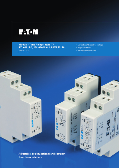
Modular Time Relays, type TRIEC 61812-1, IEC 61000-6-2 & EN 50178 Product Guide •Variable ac/dc control voltage •High accurracy•18 mm module widthAdjustable, multifunctional and compact Time Relay solutionsModular time relays, type TR12Modular time relays, type TR PG04910001U - July 2006Modulartimerelays,typeTR1Eaton time relays including all time delay functionsFor further details about the different functionalities of time relays, are explained in chapter 2.Here you find a detailed description of the individual functionalities, supported by pictograms.Reference of available functions by typeType TRL04TRL07TRLPGFunctionON Delay (voltage controlled)X XOFF Delay (with control input)X XSingle shot leading edge (with control input)XSingle shot trailing edge (with control input)XON Delay (with control input)XSingle shot leading edge (voltage controlled)X XSymmetric pulse generator (pause first)X XAsymmetric pulse generator (pause first)XAsymmetric pulse generator (pulse first)X3PG04910001U - July 2006Modular time relays, type TRM o d u l a r t i m e r e l a y s , t y p e T R1Available functions are:E = ON Delay (voltage controlled)R = OFF Delay (with control input)Wu = Single shot leading edge (voltage controlled)Bp = Symmetric pulse generator (pause first)Available functions are:E = ON Delay (voltage controlled)R = OFF Delay (with control input)Ws = Single shot leading edge (with control input)Wa = Single shot trailing edge (with control input)Es = ON Delay (with control input)Wu = Single shot leading edge (voltage controlled)Bp = Symmetric pulse generator (pause first)Available functions are:Ip = Asymmetric pulse generator (pause first)Ii = Asymmetric pulse generator (pulse first)TRL04DescriptionAvailable functionsNominal current Contact configurationSupply & controlvoltage inputWidthQPCEatonlist numberTime relay, multifunctional - with 4 functionsE, R, Wu, Bp 8 A 1 co 24…240 Vac/dc 18 mm 1TRL04TRL07DescriptionAvailable functionsNominal currentContactconfigurationSupply & control voltage inputWidthQPCEatonlist numberTime relay, multifunctional - with 7 functions E, R, Ws, Wa, Es, Wu, Bp 8 A1 co 12…240 Vac/dc 18 mm 1TRL07TRLPGDescriptionAvailable functionsNominal current Contact configurationSupply & controlvoltage inputWidthQPCEatonlist numberTime relay, asymmetric pulse generatorIp, Ii 8 A 1 co 12…240 Vac/dc 18 mm 1TRLPGModular time relays, technical details24Modular time relays, technical details PG04910001U - July 2006Modulartimerelays,technicaldetails2ON Delay - voltage controlled (E)When the supply voltage U is applied, the set interval t begins (green LED U/t flashes). After the interval t has expired(green LED U/t illuminated) the output relay R switches into on-position (yellow LED illuminated). This status remains until the supply voltage is interrupted. If the supply voltage is interrupted before the expiry of the interval t, the interval already expired is erased and is restarted when the supply voltage is next applied.OFF Delay - with control input (R)The supply voltage U must be constantly applied to the device (green LED U/t illuminated). When the control contact S is closed, the output relay R switches into on-position (yellow LED illuminated). If the control contact is opened, the set interval t begins (green LED flashes). After the interval t has expired (green LED U/t illuminated) the output relay switches into off-position (yellow LED notilluminated). If the control contact is closed again before the interval t has expired, the interval already expired is erased and is restarted.Single shot leading edge - with control input (Ws)The supply voltage U must be constantly applied to the device (green LED U/t illuminated). When the control contact S is closed, the output relay R switches into on-position (green LED U/t illuminated) and the set interval t begins (green LED U/t flashes). After theinterval t has expired (green LED U/t illuminated) the output relay switches into off-position (yellow LED not illuminated). During the interval, the control contact can be operated any number of times. A further cycle can only be started when the cycle run has been completed.Single shot trailing edge - with control input (Wa)The supply voltage U must be constantly applied to the device (green LED U/t illuminated). Closing the control contact S has noinfluence on the condition of the output R. When the control contact is opened, the output relay switches into on-position (yellow LED illuminated) and the set interval t begins (green LED U/t flashes). After the interval t has expired (green LED U/t illuminated), the ouput relay switches into off-position (yellow LED not illuminated). During the interval, the control contact can be operated any number of times. A further cycle can only be started when the cycle run has been completed.Time relays, reference of available functions by type.5PG04910001U - July 2006Modular time relays, technical detailsM o d u l a r t i m e r e l a y s , t e c h n i c a l d e t a i l s2ON Delay - with control input (Es)The supply voltage U must be constantly applied to the device (green LED U/t illuminated). When the control contact S is closed, the set interval t begins (green LED U/t flashes). After the interval t has expired (green LED U/t illuminated) the output relay R switches into on-position (yellow LED illuminated). This status remains until the control contact is opened again. If the control contact is opened before the interval t has expired, the interval already expired is erased and is restarted with the next cycle.Single shot leading edge - voltage controlled (Wu)When the supply voltage U is applied, the output relay R switches into on-position (yellow LED illuminated) and the set interval t begins (green LED U/t flashes). After the interval t has expired (green LED U/t illuminated) the output relay switches into off-position(yellow LED not illuminated). This status remains until the supply voltage is interrupted. If the supply voltage is interrupted before the interval t has expired, the output relay switches into off-position. The interval already is erased and is restarted when the supply voltage is next applied.Symmetric pulse generator - pause first (Bp)When the supply voltage U is applied, the set interval t begins (green LED U/t flashes). After the interval t has expired, theoutput relay R switches into on-position (yellow LED illuminated) and the set interval t begins again. After the interval t has expired, the output relay switches into off-position (yellow LED not illuminated). The output relay is triggered at a ratio of 1:1 until the supply voltage is interrupted.Asymmetric pulse generator - pause first (Ip)When the supply voltage U is applied, the set interval t1 begins (green LED U/t flashes slowly). After the interval t1 has expired, the output relay R switches into on-position (yellow LED illuminated) and the set interval t2 begins (green LED U/t flashes fast). After the interval t2 has expired, the output relay switches into off-position (yellow LED not illumminated). The output relay is triggered at the ratio of t1:t2 until the supply voltage is interrupted.Asymmetric pulse generator - pulse first (Ii)When the supply voltage U is applied, the output relay R switches into on-position (yellow LED illuminated) and the set interval t1 begins (green LED U/t flashes slowly). After the interval t1 has expired, the output relay switches into off-position (yellow LED not illuminated) and the set interval t2 begins (green LED U/t flashes fast). After the interval t2 has expired, the output relay switches intoon-position (yellow LED illuminated). The output relay is triggered at the ratio of t1:t2 until the supply voltage is interrupted.6Modular time relays, technical details PG04910001U - July 2006M o d u l a r t i m e r e l a y s , t e c h n i c a l d e t a i l s2Time relays, dimensional drawings, type TRTime relays, connection schemes, type TRTime relays, type TRTRL04/TRL07 with control input. TRL04/TRL07 without control input.TRLPG.7PG04910001U - July 2006Modular time relays, technical detailsM o d u l a r t i m e r e l a y s , t e c h n i c a l d e t a i l s2Time relays, technical details, type TRProductsTime relays, type TRTRL04TRL07TRLPGGeneralMain Standards IEC 61812-1, IEC 61000-6-2, EN 50178Additional standards IEC 61000-6-3, IEC 61000-4-2, IEC 61000-4-4, IEC 61000-4-6Protection class open airIP20IP20IP20Protection class enclosed (accessible front)IP40IP40IP40Permissible ambient temperature (acc. IEC 68-1)-25…+55 °C -25…+55 °C -25…+55 °C Storage temperature-25…+70 °C -25…+70 °C -25…+70 °C Relative humidity (acc. IEC 721-3-3 class 3K3)15% to 85%15% to 85%15% tot85%Pollution degree (acc. IEC 664-1)Class 2, if built-in class 3Class 2, if built-in class 3Class 2, if built-in class 3Vibration resistance (acc. IEC 68-2-6)10 to 55 Hz / 0,35 mm 10 to 55 Hz / 0,35 mm 10 to 55 Hz / 0,35 mm Shock resistance (acc. IEC 68-2-27)15 g 11 ms 15 g 11 ms 15 g 11 ms Mounting positionanyanyanyIncoming supply circuitSupply voltage24 - 240 V ac/dc12 - 240 V ac/dc 12 - 240 V ac/dc Supply voltage tolerance 24 V -/- 15%...- 240 V + 10%12 V -/- 10%.....- 240 V + 10%12 V -/- 10%.....- 240 V +10%Incoming supply terminals A1(+) - A2A1(+) - A2A1(+) - A2Rated power consumption 4 VA (1,5W) 4 VA (1,5W) 4 VA (1,5W)Rated frequency for ac voltage 48 to 63 Hz 48 to 63 Hz 48 to 63 Hz Duty cycle 100%100%100%Reset time100 ms 100 ms 100 ms Residual ripple to DC 10%10%10%Drop off voltage> 30% of nominal voltage> 30% of nominal voltage > 30% of nominal voltage Rated impulse withstand voltage U imp4 kV 4 kV 4 kV Overvoltage category (acc. IEC 60664-1)IIIIIIIIIIncoming control circuitControl supply terminals A1-B1A1-B1A1-B1Loadableyes yes yes Maximum cable length 10 mtr.10 mtr.10 mtr.Trigger level (sensitivity)Automatic adaptation to supply voltage Automatic adaptation to supply voltage Automatic adaptation to supply voltage Minimum duration control pulse length at ac 100 ms 100 ms -Minimum duration control pulse length at dc50 ms50 ms-8Modular time relays, technical details PG04910001U - July 2006M o d u l a r t i m e r e l a y s , t e c h n i c a l d e t a i l s2Products Time relays, type TRTRL04TRL07TRLPGOutgoing circuitOutgoing potential free contact 1 x co 1 x co 1 x co Rated voltage250 V ac250 V ac250 V acSwitching capacity ac *)2000 VA (8 A / 250 V)2000 VA (8 A / 250 V)2000 VA (8 A / 250 V)Switching capacity dc *)50 VA50 VA50 VAMaximum lamp load: *)Incandescent lamp 500 VA 500 VA 500 VA Energy saving lamp50 VA 50 VA 50 VA Fluorescent lamp single - Uncompensated (inductive)120 VA 120 VA 120 VA Fluorescent lamp single - Compensated (capacitive)36 VA 36 VA 36 VA Fluorescent lamp double - Series compensated 360 VA 360 VA 360 VA Fluorescent lamp single/double - HF Electronic120 VA 120 VA 120 VA Mechanical endurance20.000.000 x 20.000.000 x 20.000.000 x Electrical endurance at 1000 VA cosphi = 1,0200.000 x 200.000 x 200.000 x Maximum switching frequency at 100 VA pf=1,0 (acc. IEC 947-5-1)60x / min 60x / min 60x / min Maximum switching frequency at 1000 VA pf=1,0 (acc. IEC 947-5-1)6x / min6x / min6x / minMaximum back-up fuse - fast acting 8 A fast 8 A fast 8 A fast Rated impulse withstand voltage U imp4 kV 4 kV 4 kV Overvoltage category (acc. IEC 60664-1)IIIIIIIIIAccuracyBase accuracy ±1% of maximum scale value±1% of maximum scale value±1% vof maximum scale valueAdjusting accuracy < 5% of maximum scale value< 5% of maximum scale value< 5% vof maximum scale valueRepetition accuracy < 0,5% or ±5 ms < 0,5% or ±5 ms < 0,5% or ±5 ms Voltage influence ---Temperature influence< 0,01% / °C< 0,01% / °C< 0,01% / °CDimensions & weightWidth 18 mm 18 mm 18 mm Height87 mm 87 mm 87 mm Depth (excl. DIN-profile)60 mm 60 mm 60 mm Weight72 gram72 gram72 gramTerminals for main & auxiliary contactsTerminal capacity1 x 0,5....2,5 mm2 with/without multicore cable end 1 x 4 mm 2 without multicore cable end 2 x 0,5....1,5 mm 2 without multicore cable end 2 x 2,5 mm 2 flexible with/without multicore cable endTerminal screw head type (Pozidrive)PZ 1PZ 1PZ 1Maximum torque1,0 Nm1,0 Nm1,0 NmNote:*)In case multipole circuits are installed in one panel it is required to multiply above mentioned (lamp)load by the applicable load factor according the IEC 60439-1.+61 2 9693 9388+61 2 9693 1258************************************(toll-freeline)*************************************************************。
模块化设计

模块化 设计方式
02.模块化设计方式
Modular design approach
模块化 设计方式
3)横系列和跨系列模块化设计:除发展横
系列产品之外,改变某些模块还能得到其它系 列产品 者,便属于横系列和跨系列模块化设计了。德国沙曼 机床厂生产的模块化镗铣床,除 可发展横系列的数控 及各型镗铣加工中心外,更换立柱、滑座及工作台, 即可将镗铣床变为 跨系列的落地镗床。
Modular review and development
▲原始模块化
语言革命:语言是人有别于动物的关键环节,汉 语语音(包括四声)共有415个,经组合能表达 极其复杂的内容。
04.模块化回顾与发展
Modular review and development
▲原始模块化
文字革命:每一个汉字都具有特殊的形态和特定 意义,文字组合可形成表达不同思想的文件。汉 字是公用的通用单元。
Modular three big characteristics
互换性
有利于实现横系列、纵系列产品间的模块的通用,实现跨系列产 品间的模块的通用
04.模块化回顾与发展
Modular review and development
▲原始模块化
▲经典模块化
▲现代模块化
▲模块化时代
04.模块化回顾与发展
04.模块化回顾与发展
Modular review and development
▲原始模块化
印刷革命:活字印刷术加速了信息的传播,极大 地推进了人类社会的进步。用字模排版印刷,拆 版后通用的活字可复用。
04.模块化回顾与发展
Modular review and development
海上油气生产平台手动报警站回路实时监控系统

· 154 ·
价值工程
海上油气生产平台手动报警站回路实时监控系统
Real-time Monitoring System of Manual Alarm Station Loop for Offshore Oil and Gas Production Platform
朱志星 ZHU Zhi-xing
(中海油深圳分公司流花油田作业区,深圳 518000) (Liuhua Oilfield Operation Area of CNOOC Shenzhen Branch,Shenzhen 518000,China)
传输到安全系统 PLC 后,经过逻辑判断输出相应的火气
报警信号及生产关停信号。服务器通过交换机访问 PLC 处理器,采集数据,通过上位机 IFIX 软件显示监控画面, 实现可监视平台监测探头回路故障、系统故障并及时报警 要要要要要要要要要要要要要要要要要要要要要要要
图 2 手动报警站分类图
设计冰箱时的想法英语作文

设计冰箱时的想法英语作文Title: Innovative Concepts in Refrigerator Design。
Refrigerators have become an indispensable part of modern households, serving as a cornerstone for food preservation. Designing a refrigerator involves a delicate balance between functionality, energy efficiency, and aesthetic appeal. In this essay, I will explore innovative ideas for refrigerator design that address these aspects while also considering environmental sustainability.First and foremost, energy efficiency is paramount in refrigerator design. Traditional refrigerators consume a significant amount of energy, contributing to high electricity bills and environmental degradation. One innovative approach to address this issue is the implementation of advanced insulation materials. Utilizing materials with superior thermal properties can minimize heat transfer, reducing the workload on the refrigerator's compressor and consequently decreasing energy consumption.Moreover, incorporating smart technology into refrigerator design can enhance energy efficiency and user convenience. Smart refrigerators equipped with sensors and artificial intelligence algorithms can optimize cooling settings based on usage patterns and external factors such as ambient temperature. Additionally, features like automatic door closure mechanisms and energy-saving modes can further minimize energy wastage.Another key aspect of refrigerator design is space optimization. With urban living spaces becoming increasingly compact, maximizing storage capacity within a limited footprint is essential. One innovative solution is the integration of adjustable shelving systems and modular compartments. These features allow users to customize the interior layout according to their specific storage needs, accommodating items of varying sizes and shapes more efficiently.Furthermore, incorporating sustainable materials and manufacturing processes is imperative in contemporaryrefrigerator design. Traditional refrigerators oftenutilize materials that are harmful to the environment, such as chlorofluorocarbons (CFCs) and polyvinyl chloride (PVC). In contrast, utilizing recycled and recyclable materialscan significantly reduce the ecological footprint of refrigerators. Additionally, adopting eco-friendly manufacturing practices, such as reducing water usage and minimizing waste generation, can further enhance the sustainability of refrigerator production.In terms of user experience, intuitive interface design plays a crucial role in enhancing usability and convenience. Modern consumers expect seamless interaction with their appliances, and intuitive control panels and userinterfaces can greatly improve the overall user experience. Incorporating features such as touchscreen displays, voice command capabilities, and smartphone integration enables users to monitor and control their refrigerators effortlessly, even remotely.Moreover, aesthetics are an integral aspect of refrigerator design, as appliances are often prominentfixtures in kitchen interiors. Striking a balance between functionality and visual appeal is essential to create a harmonious living space. Incorporating sleek and minimalist designs, as well as offering a diverse range of color options, allows consumers to choose refrigerators that complement their individual tastes and home decor styles.In conclusion, designing innovative refrigerators involves a multifaceted approach that considers energy efficiency, space optimization, sustainability, user experience, and aesthetics. By incorporating advanced technologies, sustainable materials, and intuitive design principles, refrigerator manufacturers can create products that not only meet the needs of consumers but also contribute to a more sustainable and enjoyable living environment.。
朗威自动化PowerFlex 525 AC驱动器说明书

Rockwell Automation Publication PFLEX-SG002H-EN-P - February 2014 49PowerFlex 525 AC drives feature an innovative, modular design o ering fast and easy installation and con guration. These cost-e ective compact drives come with embedded EtherNet/IP™ communications, safety, USB con guration and a high ambient operating temperature capability. PowerFlex 525 AC drives also provide a variety of motor control algorithmsincluding volts per hertz, sensorless vector control and closed loop velocity vector control, making these drives ideal for a vastarray of applications.PowerFlex 525 AC DriveseparatelyIsolation Transformers and Input Line Reactors are available, see page 56.External EMC Filter is optional (see page 53). Drive catalog numbers are available with an integral lter and without.Output Reactors, Terminators and Re ected Wave Devices are optional (see pages 54…56).Embedded I/O7 Digital Inputs, 2 Digital Outputs, 2 Analog Inputs, 1 Analog Output,2 Relay OutputsInternal Brake IGBT See page 55 for Brake ResistorsPowerFlex 525 AC Drive50 Rockwell Automation Publication PFLEX-SG002H-EN-P - February 2014Additional InformationPowerFlex 520-Series Technical Data, publication 520-TD001 PowerFlex 520-Series User Manual, publication 520-UM001Catalog Number Explanation Product Selection100…120V AC, Single-Phase Input, Three-Phase Output Drives, 50/60 HzDrive Ratings No Filterwith Integral EMC FilterNormal Duty Heavy DutyOutput CurrentFrame SizeCat. No.Cat. No.kW Hp kW Hp A 0.40.50.40.5 2.5A 25B-V2P5N104–0.7510.751 4.8B 25B-V4P8N104–1.11.51.11.56B25B-V6P0N104–200…240V AC, Single-Phase Input, Three-Phase Output Drives, 50/60 HzDrive Ratings No Filterwith Integral EMC Filter ‡Normal Duty Heavy DutyOutput CurrentFrame SizeCat. No.Cat. No.kW Hp kW Hp A 0.40.50.40.5 2.5A 25B-A2P5N10425B-A2P5N1140.7510.751 4.8A 25B-A4P8N10425B-A4P8N1141.52 1.528B 25B-A8P0N10425B-A8P0N1142.232.2311B25B-A011N10425B-A011N114‡This filter is suitable for use with cable lengths up to 10 meters (32.8 feet) for C2 spec and 20 meters (65.6 feet) for C3 spec.200…240V AC, Three-Phase, 50/60 HzDrive Ratings No Filterwith Integral EMC FilterNormal Duty Heavy DutyOutput CurrentFrame SizeCat. No.Cat. No.kW Hp kW Hp A 0.40.50.40.5 2.5A 25B-B2P5N104–0.7510.7515A 25B-B5P0N104–1.52 1.528A 25B-B8P0N104–2.23 2.2311A 25B-B011N104–454517.5B 25B-B017N104–5.57.5 5.57.524C 25B-B024N104–7.5107.51032.2D 25B-B032N104–1115111548.3E 25B-B048N104–1520111562.1E25B-B062N104–25B4EnclosureVoltage RatingRatingInternal EMC Filter 0 = No 1 = YesPowerFlex 525 AC DriveRockwell Automation Publication PFLEX-SG002H-EN-P - February 2014 51380…480V AC, Three-Phase, 50/60 HzDrive Ratings No Filterwith Integral EMC Filter ‡Normal Duty Heavy DutyOutput CurrentFrame SizeCat. No.Cat. No.kW Hp kW Hp A 0.40.50.40.5 1.4A 25B-D1P4N10425B-D1P4N1140.7510.751 2.3A 25B-D2P3N10425B-D2P3N1141.52 1.524A 25B-D4P0N10425B-D4P0N1142.23 2.236A 25B-D6P0N10425B-D6P0N114454510.5B 25B-D010N10425B-D010N1145.57.5 5.57.513C 25B-D013N10425B-D013N1147.5107.51017C 25B-D017N10425B-D017N1141115111524D 25B-D024N10425B-D024N1141520111530D 25B-D030N10425B-D030N11418.525152037E 25B-D037N114 §25B-D037N114223018.52543E25B-D043N114 §25B-D043N114‡ This filter is suitable for use with cable lengths up to 10 meters (32.8 feet) for C2 spec and 20 meters (65.6 feet) for C3 spec.§With EMC filter.525…600V AC, Three-Phase, 50/60 HzDrive Ratings No Filterwith Integral EMC FilterNormal Duty Heavy DutyOutput CurrentFrame SizeCat. No.Cat. No.kW Hp kW Hp A 0.40.50.40.50.9A 25B-E0P9N104–0.7510.751 1.7A 25B-E1P7N104–1.52 1.523A 25B-E3P0N104–2.23 2.23 4.2A 25B-E4P2N104–4545 6.6B 25B-E6P6N104–5.57.5 5.57.59.9C 25B-E9P9N104–7.5107.51012C 25B-E012N104–1115111519D 25B-E019N104–1520111522D 25B-E022N104–18.525152027E 25B-E027N104–223018.52532E25B-E032N104–Approximate Dimensions and WeightsDimensions are in mm (in.) - weights are in kg (lb)IP20, NEMA/UL Type OpenFrame H W D Weight A 152.0 (5.98)72.0 (2.83)172.0 (6.77) 1.10 (2.4)B 180.0 (7.08)87.0 (3.42)172.0 (6.77) 1.60 (3.5)C 220.0 (8.66)109.0 (4.29)184.0 (7.24) 2.30 (5.1)D 260.0 (10.23)130.0 (5.11)212.0 (8.34) 3.20 (7.1)E300.0 (11.81)185.0 (7.28)279.0 (10.98)12.90 (28.4)Human Interface Modules and AccessoriesDescription Cat. No. Remote (Panel Mount) LCD Display, Digital Speed Control, CopyCat Capable. Includes 2.0 meter cable. IP66, NEMA Type 4X/12 - Indoor Use Only.22-HIM-C2S h Remote Handheld, LCD Display, Full Numeric Keypad, Digital Speed Control, CopyCat Capable. Includes 1.0 meter cable. IP30, NEMA Type 1. Panel mount with optional BezelKit.22-HIM-A3 Bezel Kit. Panel Mount for LCD Display, Remote Handheld Unit. IP30, NEMA Type 1. Includes a 22-RJ45CBL-C20 cable.22-HIM-B1 DSI HIM Cable (DSI HIM to RJ45 cable)1.0 Meter (3.3 Feet)22-HIM-H102.9 Meter (9.5 Feet)22-HIM-H30h The 22-HIM-C2S is smaller than the 22-HIM-C2 and cannot be used as a direct replacement.Communication Option KitsDescription Cat. No. DeviceNet™ Communication Adapter25-COMM-D EtherNet/IP™ Communication Adapter - Dual Port25-COMM-E2P PROFIBUS™ DP Communication Adapter25-COMM-P Serial Converter Module (RS485 to RS232). Provides serial communication via DF1 protocol for use with DriveExplorer and DriveExecutive™ software. Includes DSI to RS232serial converter, 1203-SFC serial cable, 22-RJ45CBL-C20 cable, and DriveExplorer Lite CD.22-SCM-232 Serial Cable. 2.0 meter with a locking low profile connector. Connects the serial converter to a 9-pin sub-miniature D female computer connector.1203-SFC Serial Null Modem Adapter. Use when connecting the serial converter to DriveExplorer on a handheld PC.1203-SNM Universal Serial Bus™ (USB) Converter includes 2m USB, 20-HIM-H10 and 22-HIM-H10 Cables.1203-USB DSI Cable. 2.0 meter RJ45 to RJ45 cable, male to male connectors.22-RJ45CBL-C20 Splitter Cable. RJ45 one to two port splitter cable.AK-U0-RJ45-SC1 Terminal Block. RJ45 two position terminal block (6 pieces) with two 120 Ohm terminating resistors (loose).AK-U0-RJ45-TB2P Terminating Resistors. 120 Ohm resistor embedded in an RJ45 connector (2 pieces).AK-U0-RJ45-TR1 DSI External Communications Kit. External mounting kit for 22-COMM Communication Adapters.22-XCOMM-DC-BASE External Communications Kit Power SupplyOptional 100…240V AC Power Supply for External DSI Communications Kit.20-XCOMM-AC-PS1 Compact I/O Module (3 Channel)1769-SM2IP30, NEMA/UL Type 1 Conversion KitDescription Frame Cat. No. Converts IP20 drive to IP30, NEMA/UL Type 1 enclosure A25-JBAAB25-JBABC25-JBACD25-JBADE25-JBAE Other OptionsDescription Frame Cat. No. EMC Grounding Plate A25-EMC1-FAB25-EMC1-FBC25-EMC1-FCD25-EMC1-FDE25-EMC1-FE Mounting Adapter Plate, Bulletin 160 AC Drive toPowerFlex 525A25-MAP-FAB25-MAP-FB Incremental Encoder for PowerFlex 525All25-ENC-1 Control Module Fan Kit for 70 °C operation and/orhorizontal drive mounting.A…D25-FAN1-70CE25-FAN2-70CPowerFlex 520-Series Options52Rockwell Automation Publication PFLEX-SG002H-EN-P - February 2014PowerFlex 520-Series OptionsRockwell Automation Publication PFLEX-SG002H-EN-P - February 2014 53EMC Filters (Required to Meet CE Certi cation)Drive RatingsCat. No.Input Voltage kW Hp Frame 100 …120V, Single-Phase, 50/60 Hz 0.20.25A 25-RF011-AL 0.40.5A 0.751B 25-RF023-BL 11.5B 200…240V, Single-Phase, 50/60 Hz 0.20.25A 25-RF011-AL0.40.5A 0.751A 1.52B 25-RF023-BL 2.23B 200…240V, Three-Phase 50/60 Hz,0.20.25A 25-RF014-AL0.40.5A 0.751A 1.52A 2.23A 3.75B 25-RF021-BL 5.57.5C 25-RF027-CL 7.510D 25-RF035-DL 1115E 25-RF056-EL 1520E 380…480V, Three-Phase 50/60 Hz 0.40.5A 25-RF7P5-AL0.751A 1.52A 2.23A 3.75B 25-RF014-BL 5.57.5C 25-RF018-CL 7.510C 1115D 25-RF033-DL 1520D 18.525E 25-RF039-EL 2230E 525…600V, Three-Phase, 50/60 Hz 0.40.5A 25-RF8P0-BL0.751A 1.52A 2.23A 3.75B 5.57.5C 25-RF014-CL 7.510C 1115D 25-RF027-DL 1520D 18.525E 25-RF029-EL2230EControl ModuleDescriptionFrame Cat. No.PowerFlex 523 Control Module (includes control module front cover)All 25A-CTM1PowerFlex 525 Control Module (includes control module front cover)All25B-CTM1Power Modules §Ratings No Filter with Integral EMC Filter Input Voltage Normal Duty Heavy DutykW Hp kW Hp Cat No.Cat No.100…120V AC, Single-Phase, 50/60 Hz 0.20.250.20.2525-PM1-V1P6–0.40.50.40.525-PM1-V2P5–0.7510.75125-PM1-V4P8–1.52 1..5225-PM1-V6P0–200…240V AC, Single-Phase, 50/60 Hz0.20.250.20.2525-PM1-A1P625-PM2-A1P60.40.50.40.525-PM1-A2P525-PM2-A2P50.7510.75125-PM1-A4P825-PM2-A4P81.52 1.5225-PM1-A8P025-PM2-A8P02.23 2.2325-PM1-A01125-PM2-A011200…240V AC, Three-Phase, 50/60 Hz0.20.250.20.2525-PM1-B1P6–0.40.50.40.525-PM1-B2P5–0.7510.75125-PM1-B5P0–1.52 1.5225-PM1-B8P0–2.23 2.2325-PM1-B011–454525-PM1-B017–5.57.5 5.57.525-PM1-B024–7.5107.51025-PM1-B032–1115111525-PM1-B048–1520111525-PM1-B062–380…480V AC, Three-Phase, 50/60 Hz0.40.50.40.525-PM1-D1P425-PM2-D1P40.7510.75125-PM1-D2P325-PM2-D2P31.52 1.5225-PM1-D4P025-PM2-D4P02.23 2.2325-PM1-D6P025-PM2-D6P0454525-PM1-D01025-PM2-D0105.57.5 5.57.525-PM1-D01325-PM2-D0137.5107.51025-PM1-D01725-PM2-D0171115111525-PM1-D02425-PM2-D0241520111525-PM1-D03025-PM2-D03018.5251520–25-PM2-D037223018.525–25-PM2-D043525…600V AC, Three-Phase, 50/60 Hz0.40.50.40.525-PM1-E0P9–0.7510.75125-PM1-E1P7–1.52 1.5225-PM1-E3P0–2.23 2.2325-PM1-E4P2–454525-PM1-E6P6–5.57.5 5.57.525-PM1-E9P9–7.5107.51025-PM1-E012–1115111525-PM1-E019–1520111525-PM1-E022–18.525152025-PM1-E027–223018.52525-PM1-E032–§ Includes power module front cover (Frames B…E only).PowerFlex 520-Series Options54 Rockwell Automation Publication PFLEX-SG002H-EN-P - February 2014AccessoriesDescriptionFrame Cat. No.Power Module Front CoverB 25-PMFC-FBC 25-PMFC-FCD 25-PMFC-FDE 25-PMFC-FE PowerFlex 523 Control Module Front Cover All 25A-CTMFC1PowerFlex 525 Control Module Front Cover All 25B-CTMFC1Heatsink Fan Replacement KitA 25-FAN1-FAB 25-FAN1-FBC 25-FAN1-FCD 25-FAN1-FDE 25-FAN1-FE Power Terminal GuardA 25-PTG1-FAB 25-PTG1-FBC 25-PTG1-FCD 25-PTG1-FD E25-PTG1-FETerminatorsDescription #Cat. No.for use with 3.7 kW (5 Hp) and below drives 1204-TFA1for use with 1.5 kW (2 Hp) and up drives1204-TFB2# For selection information, refer to Appendix A of the Wiring and Grounding Guidelines for Pulse WidthModulated (PWM) AC Drives, publication Drives-IN001.Re ected Wave Reduction ModulesVoltage kW Hp Cat. No.380… 480V AC2.2…43…51321-RWR8-DP 451321-RWR12-DP 5.57.51321-RWR18-DP 7.5101321-RWR25-DP 11151321-RWR25-DP 15201321-RWR35-DP 18.5251321-RWR45-DP 22301321-RWR55-DP 500… 600V AC451321-RWR8-EP 5.57.51321-RWR12-EP 7.5101321-RWR18-EP 11151321-RWR25-EPRe ected Wave Reduction Module with Common Mode ChokeDescription #Cat. No.17A with Common Mode Choke1204-RWC-17-A# For selection information, refer to Appendix A of the Wiring and Grounding Guidelines for Pulse WidthModulated (PWM) AC Drives, publication Drives-IN001.PowerFlex 520-Series OptionsRockwell Automation Publication PFLEX-SG002H-EN-P - February 2014 55Dynamic Brake ResistorsDrive Rating Minimum Resistance Resistance Cat. No. ‡ §VoltagekW Hp Ohms, ±10%Ohms, ±5%100…120V, 50/60 Hz, Single-Phase 0.40.56091AK-R2-091P5000.7516091AK-R2-091P5001.1 1.54891AK-R2-091P500200…240V, 50/60 Hz, Single-Phase0.40.56091AK-R2-091P5000.7516091AK-R2-091P5001.524891AK-R2-091P5002.233247AK-R2-047P500200…240V, 50/60 Hz,Three-Phase0.40.56091AK-R2-091P5000.7516091AK-R2-091P5001.526091AK-R2-091P5002.233247AK-R2-047P5003.751947AK-R2-047P5005.57.51930AK-R2-030P1K27.5101530AK-R2-030P1K211151515AK-R2-030P1K2 h 15201115AK-R2-030P1K2 h 380…480V, 50/60 Hz,Three-Phase0.40.597360AK-R2-360P5000.75197360AK-R2-360P5001.5297360AK-R2-360P5002.2397120AK-R2-120P1K24.0577120AK-R2-120P1K25.57.555120AK-R2-120P1K27.51055120AK-R2-120P1K211155060AK-R2-120P1K2 h 15205060AK-R2-120P1K2 h 18.5253040AK-R2-120P1K2 '22303040AK-R2-120P1K2 '500…600V, 50/60 Hz,Three-Phase0.40.5120360AK-R2-360P5000.751120360AK-R2-360P5001.52120360AK-R2-360P5002.23120120AK-R2-120P1K23.7582120AK-R2-120P1K25.57.565120AK-R2-120P1K27.51065120AK-R2-120P1K211156560AK-R2-120P1K2 h 15206560AK-R2-120P1K2 h 18.5256060AK-R2-120P1K2 h 22303840AK-R2-120P1K2 '‡ Resistors listed are rated 5% duty cycle.§Use of Rockwell Automation resistors is recommended. The resistors listed have been carefully selected for optimizing performance in a variety of applications. Alternative resistors may be used, however, care must be taken when making a selection. Refer to the PowerFlex Dynamic Braking Resistor Calculator, publication PFLEX-AT001.h Requires two resistors wired in parallel.' Requires three resistors wired in parallel.PowerFlex 520-Series Options56 Rockwell Automation Publication PFLEX-SG002H-EN-P - February 2014Line Reactors - 3% ImpedanceDrive RatingsIP00 #(NEMA/UL Open Type)IP11 # (NEMA/UL Type 1)Voltage kW Hp Amps Cat. No.Cat. No.200…240V, 60 Hz, Three-Phase0.40.5 4.01321-3R4-B 1321-3RA4-B 0.7518.01321-3R8-B 1321-3RA8-B 1.528.01321-3R8-A 1321-3RA8-A 2.23121321-3R12-A 1321-3RA12-A 3.7517.51321-3R18-A 1321-3RA18-A 5.57.5241321-3R25-A 1321-3RA25-A 7.510331321-3R35-A 1321-3RA35-A 1115491321-3R45-A 1321-3RA45-A 1520651321-3R55-A 1321-3RA55-A 380…480V, 60 Hz, Three-Phase0.40.5 2.01321-3R2-B 1321-3RA2-B 0.751 4.01321-3R4-C 1321-3RA4-C 1.52 4.01321-3R4-B 1321-3RA4-B 2.23 6.01321-3R8-C 1321-3RA8-C 4.0510.51321-3R8-B 1321-3RA8-B 5.57.5121321-3R12-B 1321-3RA12-B 7.510171321-3R18-B 1321-3RA18-B 1115221321-3R25-B 1321-3RA25-B 1520301321-3R35-B 1321-3RA35-B 18.525381321-3R35-B 1321-3RA35-B 223045.51321-3R45-B 1321-3RA45-B 500…600V, 60 Hz, Three-Phase0.751 2.01321-3R2-B 1321-3RA2-B 1.52 4.01321-3R4-C 1321-3RA4-C 2.23 4.01321-3R4-B 1321-3RA4-B 4.058.01321-3R8-C 1321-3RA8-C 5.57.5121321-3R12-B 1321-3RA12-B 7.510121321-3R12-B 1321-3RA12-B 1115181321-3R18-B 1321-3RA18-B 1520251321-3R25-B 1321-3RA25-B 18.525351321-3R35-C 1321-3RA35-C 2230351321-3R35-B1321-3RA35-B# Catalog numbers listed are for 3% impedance. 5% impedance reactor types are also available. Refer to 1321 Power Conditioning Products Technical Data, publication 1321-TD001.。
- 1、下载文档前请自行甄别文档内容的完整性,平台不提供额外的编辑、内容补充、找答案等附加服务。
- 2、"仅部分预览"的文档,不可在线预览部分如存在完整性等问题,可反馈申请退款(可完整预览的文档不适用该条件!)。
- 3、如文档侵犯您的权益,请联系客服反馈,我们会尽快为您处理(人工客服工作时间:9:00-18:30)。
CPU
•High-speed 32-Bit RISC CPU •> 50 MIPS, up to 120 MIPS
•Modular CT/VT configurations • up to 8 CT/VTs •High-speed digital sampling •>16 Bit A/D •> 64 samples / power cycle •High-speed 16-Bit DSP •> 32 MIPS, up to 80 MIPS
11
02. Modular Relay Design Concepts
Sub-Module Types Current & Voltage Future
CT, VT
Optical, Digital
Form-A Form-C Solid-State Wet/Dry Input
Control and Status I/O
Modular, flexible hardware architecture requires software to support it.
15
02. Modular Relay Design Concepts
Modular Software: „Object Oriented’ Design
MMS, Modbus NOT Implemented/Required
SESSION
TRANSPORT NETWORK DATA LINK PHYSICAL
SESSION
TRANSPORT NETWORK DATA LINK PHYSICAL
TCP/ IP, UDP IEEE 802.2 (CSMA/CD) IEEE 802.3 (10BaseFL) Ethernet
19‟‟ Chassis (4RU high)
Modular HMI
Modularity...
Power Supply
Power Supply
Main Processor
CPU
DSP processor + CT/VTs
DSP + CT/VT
DSP & Magnetics
•HALT/HAST limits •-40 - 130°C •High Efficiency SMPS •> 80%
Future
Analog (Transducer) I/O Future
12
Customer
1mA, 4-20mA, 0-5mA RTD (Pt, Ni, Cu) 5V, Resistive
Customer
02. Modular Relay Design Concepts
„Upgradeability‟/Serviceability „Plug n Play‟
ANALOG I/O
DIGITAL I/O
•Transducer type inputs •± dcmA •±Voltage •Resistive •Outputs for Legacy SCADA •± dcmA •Support multiple I/O configurations
•High-speed Serial •Asynchronous (9600 - 115K Baud) •Synchronous (56K - 256K Bps) •Fiber Optical (Single/Multi mode) •Channel Redundancy
Easy Module Draw-out
Field Wiring Undisturbed
Module Keying
CT Shorting „Clips‟
13
02. Modular Relay Design Concepts
Software Architecture Overview
14
02. Modular Relay Design Concepts
The ‘Universal Relay’ Family
“The engine for substation automation”
1
02. Modular Relay Design Concepts
The Challenges of the „Universal Relay’
Performance
Universal Relay
Busbar Transmission Line Generator Diagnostics Monitoring Metering Control Protection Cost ($)
Transformer Feeder
2
02. Modular Relay Design Concepts
Multiple buses allow for high-performance: •Protection and communications without bottlenecks
8
02. Modular Relay Design Concepts
Scalability
Minimum
Maximum
16
Class
Objects of the Class
02. Modular Relay Design Concepts
Building Applications: „Object Oriented’ Design
Classes
Protection Metering Control Monitoring HMI Comms
9
02. Modular Relay Design Concepts
„Box‟ Capacity CT/VT (I & V) inputs up to 3 modules
24 (max)
8/module
Status (Binary) inputs up to 6 modules Control (contact) outputs up to 6 modules
Digital I/O
Status Inputs / Control Outputs
Analog I/O
Analog Transducer I/O
Communications
COMMUNICATIONS
(Ethernet, HDLC, UART)
•Control outputs •Solid State •Electromechanical multiple types •Fast activation speeds (< 4ms) •Status inputs •Dry and Wet contacts •18 - 300 VDC •Fast detection speeds (< 4ms)
Architecture - Modular Software
Major functional elements required:
•Protection Elements •Metering Elements •Monitoring Elements •Programmable Logic and I/O control •Data and Event capture/storage •HMI programmability •Communications
Analog (Transducer) I/O up to 3 modules
10
96 (max)
16/module
48 (max)
8/module
24 (max)
8/module
02. Modular Relay Design Concepts
Configuration/Flexibility
Sub-Modules
7
02. Modular Relay Design Concepts
Inter-Module Communications
High-Speed Data Bus
High-Speed Parallel Data Bus: 80 - 100 Mbytes/sec High-Speed Serial Communications Bus: 10Mbps High-Speed Inter-Processor Serial Data Bus: 16Mbps
Modular HMI Panel
High-Speed Data Bus
Universal Relay Architecture „Modularity‟
Six Basic Modules
4
DIGITAL I/O
Status Inputs / Control Outputs
ANALOG I/O
Analog Transducer I/O
COMMUNICATIONS
(Ethernet, HDLC, UART)
Keypad
02. Modular Relay Design Concepts
Modules
Power Supply
CPU
Main Processor
High-Speed Data Bus
Physical Realization
Hardware Architecture Overview
3
02. Modular Relay Design Concepts
Power Supply
CPU
Main Processor
DSP & Magnetics
DSP processor + CT/VTs
LED LED LED Display Modules Modules Modules
UR Communications Profiles