A wide dynamic range laser rangefinder with cm-level resolution based on AGC amplifier structure
激光测径仪测量外径的方法

激光测径仪测量外径的方法Laser rangefinders are widely used in various industries to measure distances accurately and efficiently. These devices utilize a laser beam to determine the distance between the rangefinder and the target object. When measuring the outer diameter of an object, such as a pipe or a rod, there are several methods that can be employed to ensure accurate results.激光测径仪是广泛应用于各个行业的一种测量距离的设备,能够高效准确地测量距离。
这些设备利用激光束确定测距仪与目标物体之间的距离。
在测量物体的外径时,比如管道或者杆子,有几种方法可以确保准确的测量结果。
One method to measure the outer diameter of an object using a laser rangefinder is to aim the laser beam at the outer edges of the object from two different points. By taking measurements from these two points, the diameter of the object can be calculated. This method is effective for objects with uniform shapes and consistent outer edges.使用激光测径仪测量物体外径的一种方法是将激光束瞄准物体的外边缘,从两个不同的点进行测量。
Laserdyne Pty Ltd RangePRO Model HPCL-20KO 激光测距模块说

TABLE OF CONTENTSChapter Page1 DESCRIPTION 1-12 SYSTEM SPECIFICATIONS 2-12.1 System Performance 2-12.2 Communications 2-22.3 Physical Characteristics 2-22.4 Electrical Requirements 2-32.5 Environmental 2-32.6 Connector/Pin Details 2-33 OUTLINE DRAWING 3-1 LIST OF FIGURESFigure 3-1: Outline Drawing 3-11 DESCRIPTIONThe RangePRO Model HPCL-20KO is a very compact OEM laser rangefinder module providing an advanced digital rangefinding capability for military, paramilitary and commercial applications. All assemblies are integrated onto a precision bore-sighted platform. It offers higher performance than the smaller HPCL-10KO model, while remaining a spatially economic package.It integrates with host systems such as weapon, sensing, or surveillance and tracking stations, and thermal imaging cameras. It requires power and control command input, and provides range-to-target and self-diagnostic data output.The HPCL-20KO ranges at low repetition rates over distances to 30km depending on target size, target reflectivity, atmospheric conditions and customer supplied external optics (typically up to 12km for a vehicle type target).The transmitter is a collimated eye-safe laser system. It can provide ranging rates from single shot up to 40 per minute, depending on ambient temperature.The receiver incorporates an APD detector for maximum sensitivity.The unit is an open frame construction type, unsealed for environmental purposes but enclosed for EM shielding.Advanced digital signal processing techniques are employed to provide accurate, reliable ranging. Signals from the detector are digitally sampled. The samples are examined to determine all potential real target returns. If a valid target is detected within the user-set range gate it’s range data is output, if more than one target is detected within the range gate the nearest or farthest may be selected for data output.All signal and range computation is done “on the fly”. Using this philosophy, the only task remaining after the sampling has expired is to transfer the range data through the serial port. Effectively the speed of the signal processing is limited only by the data output rate.The system employs an adaptive range threshold to compensate for changing noise levels. The worst case for noise is when the system electronics are being operated at the high end of their temperature specification and when ranging is being performed in strong sunlight. The best case is the reverse situation. The adaptive range threshold feature results in more reliable ranging (fewer false alarms) when noise is elevated, and higher sensitivity (further ranging) when noise is reduced, thus maximising the system capability under varying conditions. The threshold is calculated on a “shot-by-shot” basis.RangePRO laser rangefinder software is easily upgradeable, upgrades can be downloaded in the field via a PC.2 SYSTEM SPECIFICATIONSNotation - use of brackets in tables: [notes & qualifications] (units) {alternate units}.2.1 System Performance1 Target albedo 0.3 @ 1,570nm.2 Standard clear atmosphere; extinction coefficient 0.038 km-1 @ 1,570nm (Beta Spec); sea level visibility = 23.5km.3 Target range 1000m; target albedo 100%; target size large; standard clear atmosphere; probability of detection 90%.4 At room temperature. A longer cool down period (TBD) will be required at high temperature.2.2 Communications2.3 Physical Characteristics5 Australian/NewZealand Standard AS/NZS 2211.1:1997 Laser Safety Part 1: Equipment classification, requirements and user’s guide.6 Some kinematic isolation is recommended to be provided by the installer.7 Tapped mounting holes and mechanical interface surfaces are electrically conductive.2.4 Electrical Requirements2.5 Environmental2.6 Connector/Pin Details8 With some performance degradation at temperature extremes (TBD).9 Without wind chill.10 Without solar radiation.11 Limited operation at higher temperature (TBD) with further degradation of performance. 12Refer to manufacturer for details.The information contained herein is proprietary to Laserdyne Pty Ltd. No part of this work may be reproduced or copied in any way without prior written permission of Laserdyne Pty Ltd. Note: specifications herein are subject to change without notice.A Division of Laserdyne Pty Ltd A.C.N. 053 743 132P.O. Box 6541 17 Production AveGCMC Bundall MolendinarQueensland 9726 Queensland 4214 AustraliaAustraliaTel: (07) 5594 9772 Int’l Tel: 61 7 5594 9772Fax: (07) 5594 9981 Int’l Fax: 61 7 5594 9981email:***********************.auwebsite: .au3 OUTLINE DRAWINGFigure 3-1: Outline Drawing。
工程测量英语常用词汇

测量英语常用词汇一、工程测量词汇与短句:Absolute elevation 绝对高程adjusted elevation 平差高程Relative elevation 相对高程alignment 准直alignment error 校正误差/alignment stake 定线桩pileallowed error 容许误差/artificial error 人为误差assumed elevation 假定高程测量放样setting out/轴线放样setting out of axis/ background 背景/back sight 后视base measurement 基线测量/base-line 基线/bearing mark 方位标记bench level 水准点高程/bench mark(BM) 水准点,基准点calculation error 计算误差/ check 检核/ check measuring point 校核测点/check of leveling line 水准路线检测/ ground elevation 地面标高construction survey施工测量/contour等高线/extra contour 辅助等高线contour interval 等高距/ slope distance 斜距/control line/net/point 控制线,控制网,控制点coordinate 坐标/coordinate grid 坐标网格correction 改正数/detection 检测/ deviation 误差counter-clockwise 顺时针方向/design coordinate 设计坐标design elevation设计高程/detail survey详测/difference in elevation高差elevation of sight 视线高程/ elevation of line of sight 视线标高error误差/error control误差控制/error correction 误差foresight 前视/ front-view 前视图height of instrument 仪器高程/stability of instrument 仪器稳定性horizontal angle水平角/horizontal deviation 水平偏差/horizontal distance 水平距离/horizontal line 水平线land smoothing survey 土地平整测/lay out/location/locating 放样solid error 固定误差/observation error 观测误差/overall error 总误差instrument parallax 仪器视差scale比例尺/scale accuracy 比例尺精度/scale error 比例误差/spirit level 水准器set up the instrument安置仪器/setting out of axis 轴线放样/site survey 现场勘测surveying sheet 测量图/surveying stake 测量标桩/surveyors pole标杆staking-out work现场定线/state plane coordinate system /国家平面坐标系统triangulation 三角测量/tripod 三角架/turning point 转点uniform slope 等坡面/vertical control net 高程控制网/vertical control survey 高程控制测量visual observation 目测/zero elevation 零高程closure traverse 闭合导线把仪器架到这个点上,把仪器收到车里Set up the instrument over this control point/ take it back into the pick-up把棱镜立直不要动Hold the prism straight and stable在这附近有控制点吗? Is there any controlling point around?测这条路的横段面,每25m一个断面Make a survey of road transverse surface/cross section every 25meters我们给的高程是垫块的顶部高程这高程是开挖高程The elevation is for excavation/the top of the kicker请把推土机开走它挡住我的视线我们看不见棱镜了Please move away the bulldozer; it blocks my sight of the prism用白油漆在U-drain写里程桩号Write down the chainage number on U-drain with white paint我们仪器里没有这些点的坐标要一个一个的输入进去My instrument does not have the coordinates of these points; we have to put in these figures one by one.这个桩的位置不是很准确需要改一下The location of this stake/peg is not right; we have to correct it.用长皮尺测量一下这路的宽度Measure the width of road with tape measure从这点到路边的大概距离是多少?What is the general/rough distance between this point and the road sideline?从这点到路的中心线的估计高差是多少?What is the estimated elevation difference from this point to the central line?把彩条系到桩子上Tie/fasten the ribbon to pegs/stakes这个坡的坡度应该是很缓的这个坡的坡度是1:3The gradient of this slope should be flat/ is one in three.用警示条和竹竿把这个区域封上以免毁坏标杆测量学各章词汇及英文对照测绘Surveying测定survey layout setting-out survey普通测量学general survey大地测量学geodetic survey摄影测量与遥感学photogrammetry and remote sensing海洋测绘学marine surveying工程测量学engineering surveying制图学cartography测量基准面datum plane大地水准面geodetic surface; geiod铅垂线plumb-line水准面level plane参考椭球面reference ellipsoid旋转椭球rotating ellipsoid大地坐标系Geodetic coordinate system大地经度earth longitude(B)大地纬度earth latitude (L)空间直角坐标系spatial rectangular coordinates独立平面直角坐标系independent plane rectangular coordinate system高斯平面直角坐标系Gauss plane rectangular coordinate system高斯投影Gaussian projection高程系统height system高程原点height datum曲率curvity/curvature平面控制测量The plane control survey高程控制测量Elevation control survey第二章水准测量Leveling Surveying水平视线horizontal sight高程elevation height高差Difference of height后视backsight前视foresight水准尺Leveling rod水准仪The Level(instrument)水准点Bench Mark尺垫turning point plate微倾式水准仪slightly leaning level(instrument)望远镜telescope水准气泡bubble管水准器tube level bubble圆水准器round level bubble基座base物镜objectives 目镜eyepieces 聚焦透镜the focus lens 十字丝分划板the cross partition board 目镜调焦螺旋eyepiece optical screw物镜调焦螺旋objectives optical screw管水准器tube level bubble圆水准器round level bubble三脚架The tripod视差parallax视准轴Collimation axis水准点Bench mark水准路线Leveling line闭合水准路线Alosed level route:A loop level route附合水准路线A line level route:Annexed level route, 支水准路线An open-ended level route:Spur level route.转点Turning point闭合差misclosures闭合差允许误差:Misclosure allowable error检核check校正Calibration自动安平水准仪Autometic level补偿器compensator铟瓦水准尺Invar rod电子水准仪Electronic level条码尺Barcode rod误差:error微倾螺旋2. Slightly sloping spiral分划板护罩Partition board shield目镜3. Eyepiece物镜对光螺旋The objective convergence spiral制动螺旋Braking spiral微动螺旋Fine-tune the spiral底板Base8. 三角压板Triangle linking piece9. 脚螺旋Feet spiral:10. Spring cap弹簧冒11. The telescope望远镜12 . Objective 物镜13. Tube level管水准器14 .Round level manometers圆水准器15. Connections small screws: 连接小螺丝16. Shaft block: 轴座第三章角度测量Angles surveying水平角Horizontal angle(HA)竖直角The vertical angle(VA)光学经纬仪optical theodolite(transit)照准部Collimation device望远镜Telescope,竖直度盘vertical dish, vertical circle水准管Level bubble读数设备Readings equipment水平度盘Horizontal dish测微尺Micro-distance measuring sensor垂球Plumb bob对中centering整平level光学对中器optical centering device侧回法Observation set method方向观测法direction observation method竖直角指标误差Index error of vertical angle竖轴The vertical axis VV水平轴The horizontal axis HH望远镜视准轴The telescope collimation CC对中误差Plummet error目标偏心差Target eccentric error电子经纬仪Electronic theodolite第四章距离测量Distance surveying直线定向line orientation钢尺Steel tape定线Fixing line视距测量Stadia measurement电磁波测距仪Electromagnetic rangefinder微波测距仪Microwave rangefinder光电测距仪Photoelectric rangefinder激光测距仪Laser rangefinder红外测距仪Infrared rangefinder相位测距仪Phase type rangefinder脉冲式测距仪Pulsed rangefinder全反射棱镜Total reflecting prisms真北方向True north direction磁北方向Magnetic north direction坐标北方向Coordinates north direction方位角Azimuth真方位角True azimuth (A)磁方位角Magnetic azimuth(Am)坐标方位角Grid azimuth(α)磁偏角Magnetic declination子午线收敛角meridian convergence罗盘compass第五章全站仪TOTAL STATION水平制动、微动螺旋Horizontal motion clamp, Horizontal tangent screw 光学对中器Optical plummet telescope粗瞄镜Sighting collimator物镜Objective lens整平脚螺旋Leveling screw竖直制动、微动螺旋Vertical motion clamp, Vertical tangent screw目镜Telescope eyepiece管水准器Plate level圆水准器Circle level单棱镜组Single prism system超站仪(Smart station) Automatic total station , ultra station instrument 交会测量Resection measurement放样测量Setting-out survey对边测量Missing Line Measurement (MLM)悬高测量Remote Elevation Measurement (REM)第六章测量平差:Surveying Adjustment测量误差:surveying errors系统误差:Systematic error偶然误差:random error;accidental error最或是值:The most probable value多余观测:Redundant observation算术平均值:arithmetic average ;Arithmetic means精度指标:Accuracy index中误差:Root mean square error (RMSE)允许误差:Allowable error相对误差:Relative error观测值改正数:Observation correction value误差传播定律:Law of errors propagation全微分:Total differential权:Weight加权平均值:The weighted average (mean)权倒数传播定律:Weight reciprocal propagation law第七章控制测量:Control surveying碎部测量:detailed surveying平面控制网:Plane control network高程控制网:Elevation control network小区域控制网:Small area control network控制点:control points国家控制网:State Control netGPS测量:GPS surveying导线测量:traverse surveying三角测量:trigonometric survey三边测量:trilateral surveying光电测距仪:photoelectric rangefinder闭合导线:Closed traverse;附和导线:Connecting traverse;支导线:Open traverse.野外勘察:Field reconnaissance坐标方位角:Coordinates azimuth交会定点:Intersection fixed-point测边交会:Side-surveying intersection第八章大比例尺地形图测绘:Topographic Surveying and Mapping in Large Scale地形:Terrain地物:Ground feature地貌:Landscape比例尺:Scale依比例符号:Proportional symbols非比例符号:Disproportional symbols半比例尺符号(线性符号):Semi- Disproportional symbols (Linear symbols ) 地形图图式:map schemata地貌符号:Landscape symbols等高线:Contour line注记符号:Note symbols等高距:contour interval等高线平距:contour horizontal distance山头:Peak洼地:depressions示坡线:slope line山脊:Ridge 与山谷: valley合水线:Close waterline分水线:watershed line鞍部(垭口):Saddle。
尼康激光距离计COOLSHOT使用说明书

2021Cautions before useThank you for purchasing the Nikon Laser Rangefinder COOLSHOT.The COOLSHOT is a high-spec laser rangefinder specialized for measuring actual distance intended for use in leisure, sports and other outdoor situations.Please observe the following guidelines strictly so you can use the equipment properly and avoid potentially hazardous problems.Use of controls or adjustments or performance of procedures other than those specified herein may result in hazardous radiation exposure.q Before using this product, read thoroughly the “Cautions before use” and instructions on correct usage accompanying the product.q Keep this manual within reach for easy reference.q Do not disassemble or repair this product by yourself, this may result in a serious problem. A product that has been disassembled or repaired is not guaranteed by the manufacturer.• Specifications and design are subject to change without notice.• No reproduction in any form of this manual, in whole or in part (except for brief quotation in critical articles or reviews), may be made without written authorization from NIKON VISION CO., LTD.Please observe the following guidelines strictly so you can use the equipment properly and avoid potentially hazardous problems. Before using this product, read thoroughly the “Cautions before use” and instructions on correct usage accompanying the product. Keep this manual within reachfor easy reference.that any improper use ignoring the contents described herein can resultthat any improper use ignoring the contents described herein can result in potential injury or material loss.SAFETY PRECAUTIONS (Laser)The Nikon Laser Rangefinder uses anwhile looking into the optics from the objective side. Failure to do this may negatively affect or damage your eyes.• Do not aim at the eye.• Do not point the laser at people.• Do not operate the unit with other additional optical elements, such as lenses or binoculars. Using an optical instrument together with the Nikon Laser Rangefinder increases the danger of damaging the eyes.• When not measuring, please keep your fingers away from the POWER button to avoid accidentally emitting the laser beam.• When not in use for an extended period, please remove the battery from the body.• Do not disassemble/remodel/repair the Nikon Laser Rangefinder. The emitting laser may be harmful to your health. A product that has been disassembled/remodeled/repaired is not guaranteed by the manufacturer.• Keep the Nikon Laser Rangefinder out of reach of children when stored.• If the Nikon Laser Rangefinder’s body cover is damaged, or if it emits a strange sound due to dropping or some other cause, remove the battery immediately and stop using.2223Storage• Water condensation or mold may occur on the lens surface because of high humidity. Therefore, store the Nikon Laser Rangefinder in a cool, dry place.After use on a rainy day or at night, thoroughly dry it at roomtemperature, then store in a cool, dry place.CARE AND MAINTENANCE Lenses• When removing dust on the lens surface, use a soft oil-free brush.• When removing stains or smudges like fingerprints from the lenssurface, wipe the lenses very gently with a soft clean cotton cloth or quality oil-free lens tissue. Use a small quantity of pure alcohol (not denatured) to wipe stubborn smudges. Do not use velvet cloth or ordinary tissue, as it may scratch the lens surface. Once the cloth has been used for cleaning the body, it should not be used again for the lens surface.Main body• Clean the body surface with a soft, clean cloth after blowing away dust with a blower* lightly. Do not use benzene, thinner, or other cleaners containing organic solvents.* A blower is rubber cleaningequipment that blows air from a nozzle.SAFETY PRECAUTIONS (Lithium battery)If handled incorrectly, the battery may rupture and leak, corroding equipment and staining clothing. Be sure to observe the following:• Install the battery with the + and – poles positioned correctly.• The battery should be removed when exhausted or during extended periods of non-use.• Do not short the end terminal of the battery chamber.• Do not carry together with keys or coins in a pocket or bag, it may short and cause overheating.• Do not expose the battery to water, or a flame. Never disassemble the battery.• Do not charge the lithium battery.• If liquid from a damaged battery comes into contact with clothing or skin, rinse immediately with plenty of water. If liquid from a damaged battery enters the eyes, rinseimmediately with clean water, then consult a doctor.• When disposing of the battery, follow your local area regulations.Rangefinder is waterproof, it is not designed for use underwater.• Rain, water, sand and mud should be removed from the rangefinder body surface as soon as possible, using a soft, clean cloth.• Do not leave the Nikon Laser Rangefinder in a car on a hot or sunny day, or near heat-generating equipment. This may damage or negatively affect it.• Do not leave the Nikon Laser Rangefinder in direct sunlight. Ultraviolet rays and excessive heat may negatively affect or even damage the unit.• If the Nikon Laser Rangefinder is exposed to sudden changes in temperature, water condensation may occur on lens surfaces. Do not use the product until the condensation has evaporated.• Prevent children from putting rubber eyecup or small parts, etc. into their mouths. If childrenswallow such parts, consult a doctor immediately.• If using the rubber eyecup for a long period of time, some people may suffer skin inflammation. If any symptoms occur, stop using it and consult a doctor immediately.• When carrying the Nikon Laser Rangefinder, store it in the softcase.• If your Nikon Laser Rangefinder should fail to operate correctly, discontinue use immediately and consult with your local dealer for instructions on where to send it for repair.Cautions before useSAFETY PRECAUTIONS (Monocular)The Nikon Laser Rangefinder employs a monocular in its optical beam or directly at the sun when using the Nikon Laser Rangefinder, do not push the POWER button.• Do not use this product while walking. Failure to observe this may cause injury or malfunction as a result of walking intosomething, hitting others, falling or other accidents.• Do not swing around by the strap. This may result in hitting others and cause injury.• Do not place this product in an unstable place. Failure to observe this may result in falling or dropping and cause injury or malfunction.• Keep the plastic bag used to wrap this product or other small parts out of reach of children.24• Linear distance measurement range: 10-550 meters/11-600 yards• Distance measurement display step: 0.5 meter/yard・ Easy-to-aim 6x optical observation system ・ Results are displayed on an internal LCD panel ・ Measured and displayed in First Target Priority ・ Waterproof design (NOT designed for underwater usage)・ Invisible/Eyesafe EN/IEC Class 1M Laser ・ 8-second results display・ Compact, lightweight, ergonomic design・ Automatic power shut-off (after approx. 8 sec. unattended)・ Default to “Last Use” settings・ Approx. 8-second continuous measuring functionThe Nikon Laser Rangefinder uses an invisiblelaser beam for measuring. It measures the time the laser beam takes to travel from the rangefinderto the target and back. Laser reflectivity andmeasurement results may vary according to climatic and environmental conditions, as well as the color,surface finish, size, shape and other characteristics of the target.The following conditions makes measuring easier:• Night time use rather than bright daytime • Cloudy weather rather than in direct sunlight • Bright-colored targets• Targets with highly reflective surfaces • Targets with shiny exteriors • Large-size targets• Laser incident angle to the target is close to 90 degreesMeasurement may result in inaccuracy or failure in the following cases:• Slender or small target• Target has diffusing reflective surface• Target does not reflect the laser beam to the rangefinder (glass, a mirror, etc.)• Black target • Target has varying depths• In snow, rain or fog • Target measured through glass • Reflective surface measured from diagonal direction• Moving target • Obstacle moving in front of the target• When targeting the surface of water Key FeaturesNomenclature/Composition1 Monocular objective lens/Laser emission aperture 2 Laser detector aperture 3 MODE button 4 POWER button5 6x monocular eyepiece6 Eyecup/diopter adjustment ring7 Diopter index8 Strap eyelet9 Battery chamber cover!p Battery chamber cover “Open/Close” indication !q Product number label!w FDA information indication⑪⑩⑫2627• Battery lifeContinuous operation: Approx. 2,000 times (at approx. 20°C)Target focusing, measurement, and automatic power-off are included in a single cycle. This figure may differ according to condition, temperature, and other factors such as target shape, color, etc.battery will likely be shorter than that noted above.* Replace the battery if the Nikon Laser Rangefinder is ever submerged in water or if water enters the battery chamber.e.g. 234 meters = 『』 Display of results: (<100m/yards) e.g. 76.5 yards = 『』『』 - Now measuring 『』 - Failure to measure or unable to measure distance.Indicates distance being measured in yards."Changing Battery ")* Although the LCD is produced using the most advanced technology, it is impossible to eliminate dust29Operational summaryCaution — use of controls or adjustments or performance of procedures other than thosespecified herein may result in hazardous radiation exposure.1. Install a battery in the battery chamber. (See "Changing Battery")2. Diopter adjustmentAdjust diopter to obtain a clear image in the LCD. First, rotate the diopter adjustment ringcounterclockwise until it comes to a complete stop. Next, turn on the power to activate the LCD when you look through the Nikon Laser Rangefinder. Rotate the diopter adjustment ring clockwise until the display comes into focus.If the diopter is not adjusted to correspond to your eyesight, you may not be able to correctly aim at your subject.3. Measuring Before measuring, be sure to confirm unit setting.Measurement 1. Press the POWER button for power-on.(Power turns off 8 seconds after the last 2. Aim at the target2. Aim at the target 2. Aim at the target Immediately after power-on.(Initializing)Stand-by.Target focusing.3. Press POWER button once to start continuous measurement for 8 seconds. Measuring.Failure to measure orunable to measure distance.Displays the measured figure. (Target 1)Displays the measured figure. (Target 2)3. Press POWER button once to start continuous measurement for 8 seconds. (Single measurement mode is not available with this laser rangefinder.)4. For 8 seconds, the internal display shows “distance” and “fail to measure” indicator alternately. (Laser irradiation mark is blinking.)3. Press POWER button once to start continuous measurement for 8 seconds. (Single measurement mode is not available with this laser rangefinder.)4. For 8 seconds, the internal display shows “distance” and “fail to measure” indicator alternately. (Laser irradiation mark is blinking.)3. Press POWER button once to start continuous measurement for 8 seconds. (Single measurement mode is not available with this laser rangefinder.)4. For 8 seconds, the internal display shows “distance” and “fail to measure” indicator alternately. (Laser irradiation mark is blinking.)1. Press the POWER 4. For 8 seconds, the internal display shows “distance” and “fail to 3. Press POWER button once to start (Single measurement mode is not available with this laser rangefinder.)4. For 8 seconds, the internal display shows “distance” and “fail to measure” indicator alternately. (Laser irradiation mark is blinking.)When measuring the distance to a flagstick at a golf course,for example, scanning the flagstick during measuring obtainsmeasurement more easily. If there are no objects between you and "115m" (distance to the tree) will be displayed.This is useful for golf.3031SpecificationsMeasurement system Measurement rangeDistance: 10-550 meters/11-600 yards Distance display (increment)0.5 meter/yardTarget system First Target Priority System Measuring system Continuous mode Optical system TypeRoof-prism monocular Magnification (x)6Effective diameter of objective lens (mm)ø21Angular field of view (real) (˚)7.5Eye relief (mm)18.3Exit pupil (mm)ø3.5Diopter adjustment ±4m -1OthersOperating temperature (˚C)-10 — +50Power sourceC R2 lithium battery x 1 (DC 3V)Dimensions (L x H x W) (mm)111 x 70 x 40Weight (g)Approx. 165 (without battery)Structure Body: Waterproof (maximum depth of 1 meter for up to 10 minutes)*(Battery chamber: Water resistant**)Safety Class 1M Laser Product (EN/IEC60825-1:2007)Class I Laser Product (FDA/21 CFR Part 1040.10:1985)EMC FCC Part15 SubPartB class B, EU:EMC directive, AS/NZS, VCCI classB EnvironmentRoHS, WEEE* Waterproof modelsThe Nikon Laser Rangefinder is waterproof, and will suffer no damage to the optical system if submerged or dropped in water to a maximum depth of 1 meter for up to 10 minutes.The Nikon Laser Rangefinder offers the following advantages:• Can be used in conditions of high humidity, dust and rain without risk of damage.• Nitrogen-filled design makes it resistant to condensation and mold.Observe the following when using the Nikon Laser Rangefinder.• The unit should not be operated nor held in running water.• If any moisture is found on movable parts of the Nikon Laser Rangefinder, stop using it and wipe it off.To keep your Nikon Laser Rangefinder in excellent condition, Nikon Vision recommends regular servicing by an authorized dealer.** The battery chamber is water resistant, not waterproof. Water may enter the device if the Nikon Laser Rangefinder is submerged in water. If water enters the battery chamber, wipe out any moisture and allow time for the chamber to dry.Laser ClassEN/IEC Class 1M Wavelength (nm)905Pulse duration (ns)12Output (W)15Beam divergence (mrad)Vertical: 1.8, Horizontal: 0.25Operating humidity (%RH)80 (without dew condensation)3233OthersTroubleshooting/RepairIf your Nikon Laser Rangefinder should require repair, please contact your local dealer for details regarding where to send it. Before doing so, you are advised to consult the Troubleshooting Table below.SymptomCheck PointsUnit does not turn on — LCD fails to illuminate• Depress POWER button.• Check battery insertion• Replace the battery if necessary.Target range cannot be obtained• Be sure that nothing, such as your hand or finger, is blocking the laser emission aperture and laser detector.• Be sure that the laser emission aperture and laser detector are clean. Clean them if necessary.• Be sure that the target shape and condition are appropriate to reflect the laser beam.• Replace battery.[- - -] (“Cannot measure”) appears • Be sure to hold the unit steady while measuring.• Be sure the target is within measuring range (10-550m/11-600 yards)Closer target cannot be measured • Be sure that nothing, such as leaves or grass, is between the Nikon Laser Rangefinder and the target.Target beyond a certain distance cannot be measured• Be sure that nothing, such as leaves or grass, is between the Nikon Laser Rangefinder and the target.3435CONTENIDOPrecauciones antes del uso ............................... 36-39Características clave .................................................... 40Nomenclatura/Componentes .................................. 41Cambio de la batería ................................................... 42Pantalla interna .............................................................. 43Resumen operativo ............................................... 44-45Especificaciones ...................................................... 46-47Otros .................................................................................. 48Solución de problemas/Reparación ................ 49-50EspañolIf problems persist after consulting the Troubleshooting Table, please contact your local dealer to check/repair the Nikon Laser Rangefinder . Never let anyone other than the official representative of the product manufacturer check or repair the Nikon Laser Rangefinder . Failure to follow this instruction could result in injury, or damage to the product.Symptom Check PointsMeasurement result is unstable• Replace the battery.• Be sure that the target shape and condition are appropriate to reflect the laser beam.• Be sure to hold the unit steady while measuring.• Be sure that nothing, such as leaves or grass, is between the Nikon Laser Rangefinder and the target.Incorrect result is displayed• Replace battery.• Be sure that the target shape and condition are appropriate to reflect the laser beam.• Be sure that nothing, such as leaves or grass, is between the Nikon Laser Rangefinder and the target.Troubleshooting/Repair。
karto算法参数
karto算法参数"Karto"可能指的是SLAM(Simultaneous Localization and Mapping)领域的一个算法库,即Karto库。
这个库提供了一种用于机器人同时进行自主定位和地图构建的框架。
SLAM算法的参数设置通常取决于具体的实验条件、机器人平台和传感器配置。
以下是可能与Karto算法相关的一些常见参数,但请注意这些参数可能会根据具体实现和应用而有所不同:1. GridMap参数:-Resolution(分辨率):确定地图网格的大小,即每个网格表示的物理空间大小。
-MapSize(地图尺寸):地图的尺寸,通常以网格数表示。
-UpdateThreshold(更新阈值):确定在什么条件下地图需要更新。
2. LaserRangeFinder参数(激光传感器参数):-RangeThreshold(范围阈值):定义什么距离被认为是传感器有效测量的阈值。
-UseScanMatching(使用扫描匹配):决定是否使用扫描匹配算法,该算法通常用于估计机器人的运动。
-ScanMatchValidRange(扫描匹配有效范围):确定扫描匹配算法的有效范围。
3. ParticleFilter参数:-NumberOfParticles(粒子数量):确定在粒子滤波中使用的粒子数量,影响算法的计算复杂度和准确性。
4. Optimizer参数:-MaxIterations(最大迭代次数):优化算法中的最大迭代次数。
-ConvergenceThreshold(收敛阈值):决定优化算法何时达到收敛的阈值。
5. MapRepresentation参数:-MultiResolution(多分辨率):决定是否使用多分辨率地图表示。
这些参数只是示例,并且具体的参数设置可能取决于实际应用的场景和机器人平台的特性。
Fury HD 5000 猎人视角laser范围测量双筒眼镜说明书
Center FocusStrapAttachmentTripod Adapter SocketImages are for representation only. Product may vary slightly from what is shown.FURY® HD 5000 LASER RANGEFINDER BINOCULARThe Fury® HD 5000 is an extremely effective angle-compensated laser rangefinder binocular intended for hunters, archers and shooters. The primary HCD (Horizontal Component Distance) mode provides key angle compensated range information required by the vast majority of rifle and bow shooters in a simple, quick-to-read display.The Fury® HD 5000 also has a LOS (Line of Sight) mode and Scan feature, along with adjustments for reading in yards or meters and setting the brightness of the display.BASIC OPERATIONAdjust the eyecupsThe eyecups on a Fury® HD 5000twist up and down so any viewercan see the full field and enjoycomfortable viewing—with orwithout eyeglasses.When not using eyeglasses orsunglasses, keep the eyecupsfully extended. For best viewingwhen wearing eyeglasses, twisteyecups down.Adjust the interpupillary distanceThe interpupillary distance (IPD) is the distance between the centers of the left and right eye pupils. Match the IPD of your eyes to that of the binocular so you see a single image free of shading. Rotate the binocular barrels inward or outward to line your eyes up with ocular lenses.Properly focus the binocularFor the best views, follow this two-stepprocess to properly adjust the centerfocus and diopter. Choose an objectthat is about 20 yards away from youand stay in the same spot until you haveadjusted the binocular for your eyes.1. Adjust the center focus—start byclosing your left eye or covering theleft objective lens with your hand.Focus your right eye on the objectand adjust the center focus wheeluntil the image is in focus. Leavethe center focus in this position asyou adjust the diopter.2. Adjust the diopter—start by closingyour right eye or covering the rightobjective lens with your hand. Lookthrough your left eye, adjust thediopter so that the object is in focus.Make note of this diopter setting incase you need to set it again. Fromthis point on, you will only need touse the center focus wheel.Adjust Diopter SettingInstall BatteryOpen the battery compartment andinstall the CR2 battery included withthe Fury ® HD 5000.Install battery with positive sidefacing in.Power UpTo power up the Fury and prepare for ranging, press and release the Measure button. The HCD or LOS rangingscreen will display. The Fury will power down automatically after ten seconds of non-use.Low Battery IconThe low battery icon comes on at 25%and stays on until there is no power.Properly focus the rangefinder displayThis process is similar to focusing the binocular.1. Power up the binocular and close your left eye.2. View the rangefinder display with your right eye.3. Use the reticle focus adjustment ring to bring the display into sharp focus.Once this is done you will not have to refocus the rangefinder display again.+–MODE SELECTIONYour Fury ® HD 5000 is factory set to the anglecompensating HCD ranging mode, best target mode, yards, and maximum brightness. For most users, these are the preferred settings.To change modes : Press and release the Measure button to power on and then press and hold the Menu button for at least four seconds. Once the Mode Selection screen displays, release the button.As you progress through Mode Selection, you may exit at any time and save your settings by pressing and holding the Menu button for at least four seconds—the Fury will return to power-up condition.Mode Selection DisplayMenu ButtonMeasure ButtonSET AND SAVE MODE SELECTIONSRanging Mode SelectionChoose between the HCD and LOS Modes.After activating the Mode Selection, press the Measure button to toggle between the HCD and LOS displays. Press the Menu button to save your desired choice and move to the Yards/Meters selection screen.Display SelectionChoose between Yards and Meters Display.Press the Measure button to toggle between the Yards and Meters display. Press the Menu button to save your desired choice and move to the Brightness selection screen.Brightness SelectionChoose between Five Brightness Settings.The Fury® HD 5000 provides fiveillumination settings. Press the Measurebutton to toggle through the fiveBrightness settings. Press the Menubutton to save your desired setting andmove back to the target mode selection.Target Mode SelectionTarget Mode ExplanationsThe Fury HD 5000 provides two target modes: Best Mode and Last Mode.Best ModeYour Fury HD 5000 comes preset to Best target mode. This is the standard mode providing the range of the target with the strongest range result. Best Mode is the recommended target mode for most situations.Last ModeDisplays the farthest distance when panning and scanning. This mode is ideal for ranging a specific target behind a group of objects like brush, trees, rocks, etc.No Range Returned Setting Target ModesPress the Measure button to toggle between the Best and Last displays. Press the Menu button to save your desired choice and move back to the HCD/LOS selection screen.To exit Mode Selection and save settings, press and hold the Menu button for four seconds. Settings will also save when Fury powers down automatically.RANGINGWith the Fury ® HD 5000 powered up,position the reticle on the target objectand press and release the Measurebutton to get the distance measurement.If the laser is not able to range due tothe reflectivity of the target, you will seea display similar to that shown here. Torange a new target, simply re-aim andpress the Measure button again.SCAN RANGINGActivate Scan Ranging by pressing and holding the Measure button down. Keeping the button depressed will continuously measure distance as you pan back and forth across target objects. The aiming circle will blink as you pan. Releasing the Measure button will return laser to the Power Up Condition.HCD Scan LOS ScanRANGING MODE EXPLANATIONSThe Fury ® HD 5000 provides two range modes: HCD(Horizontal Component Distance) and LOS (Line of Sight). Both modes offer a Scan feature.HCD ModeThe HCD range display is intended to be the primary mode—used for most rifle and archery shootingapplications. The yardage number displayed is the critical horizontal component distance.Horizontal ComponentDistance: 385 Yards500 Y aUsing the HCD Mode• Use the HCD range mode in the following situations: • Rifle shooting on level ground at any range.• Rifle shooting out to ranges of 800 yards with mild slopes (less than 15 degrees).• Rifle shooting out to ranges of 400 yards with moderate slopes (15 to 30 degrees).• For all archery shooting.The displayed HCD yardage number is corrected for shot angle and needs no extra user input; shooters simplyuse the appropriate level ground bullet drop and wind adjustment for the range displayed and shoot. Archers use the appropriate level ground sight pin for the range displayed and shoot.LOS ModeThe LOS (Line of Sight) mode is intended for rifle shooters who are using slope correcting ballistic drop data cards, ballistic cell phone applications, or other devices with ballistic programs and who are shooting at distances beyond 500 yards and with slopes greater than 15 degrees. Most shooters and archers will not need the LOS mode. The range number displayed in LOS mode is the actual line of sight range with no ballistic correction for slope. Most of the commonly used ballistic devices can provide independent slope correction for bullet drop data and require actual line of sight range input. Using the LOS range when calculating bullet wind drifts under these steep slope/long range conditions will provide a higher degree of accuracy than using the HCD range.To use, simply input the LOS range number into the electronic device or use the LOS range when referencing ballistic drop cards with slope correction.LOS RangeIncline angle LOS Mode - InclineWhen in LOS mode, an additional number is displayed above the yardage number. This number is slope incline shown in degrees.The slope incline numbercan be entered into ballisticprograms or field cards tohelp calculate precise bulletdrops in mountainous terrain.SCAN FEATUREThe Scan feature can be used to range moving targets or help range smaller targets on uniform backgrounds, and works in both ranging and target modes. Once powered up, press and hold the Measure button and scan back and forth, watching for changes in the yardage number as the aiming circle moves across target objects. The illuminated “Scan” icon display indicates Scan Ranging is activated.TRIPOD USE FOR RANGINGUsing a tripod to steady the Fury ® HD 5000 will greatly increase your ability to range small targets at longer distances. To use on a tripod, you will need to use a binocular tripod adapter. The reticle may appear tilted depending on tripod level.RANGEFINDING TIPSRangefinding binoculars work by emitting a brief pulse of light aimed at a target object. Distance is determined by the amount of time taken for the light to emit and return to the laser’s internal receiver. A laser’s ability to read range can be affected by many things—mostly relating to the target objects.• Light colors will usually reflect better than dark ones.• Be aware that snow, rain, and fog will have adverse effects on ranging ability.• Shiny, reflective surfaces will usually reflect better than dull, textured surfaces. Animal hair will not reflect as well as a hard surface.• Ranging under cloud cover can improve laser performance compared to bright sunny conditions.• Solid objects, such as a rock, will reflect better than bushes.• Flat surfaces perpendicular to the laser pulse will reflect better than curved surfaces or surfaces angled in relation to laser pulse.• Ranging over water can sometimes cause false reflections and readings.• At longer distances, large objects will be easier to range than small objects.• If you are having difficulty ranging an animal or object, try ranging a different nearby object, or use the Scan feature to pan back and forth while watching for changes in range number.ACCESSORIESCarry CaseThe protective case provides safe storage between viewing sessions. The carry strap is already attached to the case. Lens CoversA rainguard for the ocular lenses and tethered objective lens covers is included. Use these covers to protect the lenses whenever you are not viewing.NeckstrapAttach the padded neckstrap in three simple steps.Note: If using another type of strap, never attach metal o-rings directly onto the strap attachment.1. Push a few inches ofthe strap through thestrap attachment onthe binocular.2. Hold the buckleand thread the endof the strap throughthe buckle.3. Adjust the overalllength, then pull tightuntil strap is securedwithin the buckle.LENS CAREMaintain the optical brilliance of your binocular by keeping lens surfaces free of dirt, oils, and dust.Protect Lenses While Out in the FieldMake use of the provided eyepiece and tethered objective lens covers to protect the lenses when not viewing. If the optics are exposed to moisture, keep the caps off and allow the optics to dry out completely before putting them in the case for storage.Keep Lenses CleanIn order to enjoy the best views through your binocular, take time to regularly clean the exterior lenses:1. Remove any dust or grit from lenses before wiping. Usea can of pressurized air, soft camel hair brush, or anacrylic optical brush.2. Clear lenses of smudges, fingerprints, or eyelash oil.Fog the lenses with your own breath, then use a non-abrasive lens cloth to clean the lenses.Note: Use lens cleaning fluid and opticalpaper to clean lenses. Never use facialtissue, heavy cotton, or flannel clothing onlenses—these materials can scratch thesurface of a lens.Caution: Binoculars are not intended for looking at the sun, or any other intense light source. Such viewing could damage the retina and cornea of your eyes—even to the point of causing blindness.FCC REQUIREMENTSThe user’s manual or instruction manual for an intentional or unintentional radiator shall caution the user that changes or modifications not expressly approved by the party responsible for compliance could void the user’s authority to operate the equipment.Note: This equipment has been tested and found to comply with the limits for a Class B digital device, pursuant to part 15 of the FCC Rules. These limits are designed to provide reasonable protection against harmful interference in a residential installation. This equipment generates, usesand can radiate radio frequency energy and, if not installed and used in accordance with the instructions, may cause harmful interference to radio communications. However, there is no guarantee that interference will not occur in a particular installation. If this equipment does cause harmful interference to radio or television reception, which can be determined by turning the equipment off and on, the user is encouraged to try to correct the interference by one or more of the following measures:• Reorient or relocate the receiving antenna.• Increase the separation between the equipment and receiver.• Connect the equipment into an outlet on a circuit different from that to which the receiver is connected.• Consult the dealer or an experienced radio/TV technician for help.SAFETY AND PRECAUTIONSDo not stare into beam or view directly without laser eye protection. Staring continuously into beam for prolonged periods of time could cause harm to your eyes. If used properly, this device is safe for your eyes and laser eye protection is not needed.• Use the correct battery (CR2) and proper battery orientation. • Do not look at sun.• Do not activate Menu or Measure buttons while aiming at eye or looking into objective lens.• Do not disassemble.• Do not allow children to play with unit.CAUTION—Use of controls, adjustments or performance of procedures other than those specified herein may result inhazardous laser radiation exposure.CLASS 1 LASER PRODUCTTHIS PRODUCT COMPLIES WITH IEC 60825-1:2007-03 Ed.2.0 AND IEC 60825-1:2014-05 Ed.3.0THIS PRODUCT COMPLIES WITH 21CFR SUBCHAPTER J PARTS 1040.10 AND 1040.11 EXCEPT FOR DEVIATIONS PURSUANT TO LASER NOTICE NO.50 DATED JUNE 24, 2007.VIP WARRANTY OUR UNCONDITIONAL PROMISE TO YOU.Learn more at ************************•800-426-0048Note: The VIP Warranty does not cover loss, theft, deliberate damage, or cosmetic damage not affecting product performance.We promise to repair or replacethe product. Absolutely free.UnlimitedUnconditionalLifetime WarrantyM-00243-1© 2019 Vortex Optics。
超低功耗微型超声时间差测距传感器CH101说明书
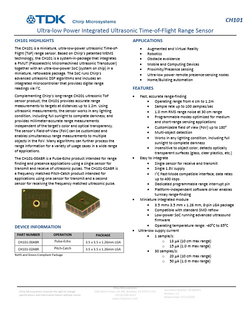
CH101 Ultra-low Power Integrated Ultrasonic Time-of-Flight Range SensorChirp Microsystems reserves the right to change specifications and information herein without notice.Chirp Microsystems2560 Ninth Street, Ste 200, Berkeley, CA 94710 U.S.A+1(510) 640–8155Document Number: DS-000331Revision: 1.2Release Date: 07/17/2020CH101 HIGHLIGHTSThe CH101 is a miniature, ultra-low-power ultrasonic Time-of-Flight (ToF) range sensor. Based on Chirp’s patented MEMS technology, the CH101 is a system-in-package that integrates a PMUT (Piezoelectric Micromachined Ultrasonic Transducer) together with an ultra-low-power SoC (system on chip) in a miniature, reflowable package. The SoC runs Chirp’s advanced ultrasonic DSP algorithms and includes an integrated microcontroller that provides digital range readings via I2C.Complementing Chirp’s long-range CH201 ultrasonic ToF sensor product, the CH101 provides accurate range measurements to targets at distances up to 1.2m. Using ultrasonic measurements, the sensor works in any lighting condition, including full sunlight to complete darkness, and provides millimeter-accurate range measurements independent of the target’s color and optical transparency. The sensor’s Field-of-View (FoV) can be customized and enables simultaneous range measurements to multiple objects in the FoV. Many algorithms can further process the range information for a variety of usage cases in a wide range of applications.The CH101-00ABR is a Pulse-Echo product intended for range finding and presence applications using a single sensor for transmit and receive of ultrasonic pulses. The CH101-02ABR is a frequency matched Pitch-Catch product intended for applications using one sensor for transmit and a second sensor for receiving the frequency matched ultrasonic pulse.DEVICE INFORMATIONPART NUMBER OPERATION PACKAGECH101-00ABR Pulse-Echo 3.5 x 3.5 x 1.26mm LGA CH101-02ABR Pitch-Catch 3.5 x 3.5 x 1.26mm LGA RoHS and Green-Compliant Package APPLICATIONS•Augmented and Virtual Reality•Robotics•Obstacle avoidance•Mobile and Computing Devices•Proximity/Presence sensing•Ultra-low power remote presence-sensing nodes •Home/Building automation FEATURES•Fast, accurate range-finding•Operating range from 4 cm to 1.2m•Sample rate up to 100 samples/sec• 1.0 mm RMS range noise at 30 cm range•Programmable modes optimized for medium and short-range sensing applications•Customizable field of view (FoV) up to 180°•Multi-object detection•Works in any lighting condition, including full sunlight to complete darkness•Insensitive to object color, detects opticallytransparent surfaces (glass, clear plastics, etc.) •Easy to integrate•Single sensor for receive and transmit•Single 1.8V supply•I2C Fast-Mode compatible interface, data rates up to 400 kbps•Dedicated programmable range interrupt pin•Platform-independent software driver enables turnkey range-finding•Miniature integrated module• 3.5 mmx 3.5 mm x 1.26 mm, 8-pin LGA package•Compatible with standard SMD reflow•Low-power SoC running advanced ultrasound firmware•Operating temperature range: -40°C to 85°C •Ultra-low supply current• 1 sample/s:o13 µA (10 cm max range)o15 µA (1.0 m max range)•30 samples/s:o20 µA (10 cm max range)o50 µA (1.0 m max range)Table of ContentsCH101 Highlights (1)Device Information (1)Applications (1)Features (1)Simplified Block Diagram (3)Absolute Maximum Ratings (4)Package Information (5)8-Pin LGA (5)Pin Configuration (5)Pin Descriptions (6)Package Dimensions (6)Electrical Characteristics (7)Electrical Characteristics (Cont’d) (8)Typical Operating Characteristics (9)Detailed Description (10)Theory of Operation (10)Device Configuration (10)Applications (11)Chirp CH101 Driver (11)Object Detection (11)Interfacing to the CH101 Ultrasonic Sensor (11)Device Modes of Operation: (12)Layout Recommendations: (13)PCB Reflow Recommendations: (14)Use of Level Shifters (14)Typical Operating Circuits (15)Ordering Information (16)Part Number Designation (16)Package Marking (17)Tape & Reel Specification (17)Shipping Label (17)Revision History (19)SIMPLIFIED BLOCK DIAGRAMFigure 1. Simplified Block DiagramABSOLUTE MAXIMUM RATINGSPARAMETER MIN. TYP. MAX. UNIT AVDD to VSS -0.3 2.2 V VDD to VSS -0.3 2.2 V SDA, SCL, PROG, RST_N to VSS -0.3 2.2 V Electrostatic Discharge (ESD)Human Body Model (HBM)(1)Charge Device Model (CDM)(2)-2-5002500kVV Latchup -100 100 mA Temperature, Operating -40 85 °C Relative Humidity, Storage 90 %RH Continuous Input Current (Any Pin) -20 20 mA Soldering Temperature (reflow) 260 °CTable 1. Absolute Maximum RatingsNotes:1.HBM Tests conducted in compliance with ANSI/ESDA/JEDEC JS-001-2014 Or JESD22-A114E2.CDM Tests conducted in compliance with JESD22-C101PACKAGE INFORMATION8-PIN LGADESCRIPTION DOCUMENT NUMBER CH101 Mechanical Integration Guide AN-000158CH101 and CH201 Ultrasonic Transceiver Handling andAssembly Guidelines AN-000159Table 2. 8-Pin LGAPIN CONFIGURATIONTop ViewFigure 2. Pin Configuration (Top View)PIN DESCRIPTIONSPIN NAME DESCRIPTION1 INT Interrupt output. Can be switched to input for triggering and calibration functions2 SCL SCL Input. I2C clock input. This pin must be pulled up externally.3 SDA SDA Input/Output. I2C data I/O. This pin must be pulled up externally.4 PROG Program Enable. Cannot be floating.5 VSS Power return.6 VDD Digital Logic Supply. Connect to externally regulated 1.8V supply. Suggest commonconnection to AVDD. If not connected locally to AVDD, b ypass with a 0.1μF capacitor asclose as possible to VDD I/O pad.7 AVDD Analog Power Supply. Connect to externally re gulated supply. Bypass with a 0.1μFcapacitor as close as possible to AVDD I/O pad.8 RESET_N Active-low reset. Cannot be floating.Table 3. Pin DescriptionsPACKAGE DIMENSIONSFigure 3. Package DimensionsELECTRICAL CHARACTERISTICSAVDD = VDD = 1.8VDC, VSS = 0V, T A = +25°C, min/max are from T A = -40°C to +85°C, unless otherwise specified.PARAMETER SYMBOL CONDITIONS MIN TYP MAX UNITSPOWER SUPPLYAnalog Power Supply AVDD 1.62 1.8 1.98 V Digital Power Supply VDD 1.62 1.8 1.98 VULTRASONIC TRANSMIT CHANNELOperating Frequency 175 kHzTXRX OPERATION (GPR FIRMWARE USED UNLESS OTHERWISE SPECIFIED)Maximum Range Max Range Wall Target58 mm Diameter Post1.2(1)0.7mm Minimum Range Min Range Short-Range F/W used 4(2)cm Measuring Rate (Sample/sec) SR 100 S/s Field of View FoV Configurable up to 180º deg Current Consumption (AVDD +VDD) I SSR=1S/s, Range=10 cmSR=1S/s, Range=1.0mSR=30S/s, Range=10 cmSR=30S/s, Range=1.0m13152050μAμAμAμA Range Noise N R Target range = 30 cm 1.0 mm, rms Measurement Time 1m max range 18 ms Programming Time 60 msTable 4. Electrical CharacteristicsNotes:1.Tested with a stationary target.2.For non-stationary objects. While objects closer than 4cm can be detected, the range measurement is not ensured.ELECTRICAL CHARACTERISTICS (CONT’D)AVDD = VDD = 1.8VDC, VSS = 0V, T A = +25°C, unless otherwise specified.PARAMETERSYMBOL CONDITIONS MINTYP MAX UNITS DIGITAL I/O CHARACTERISTICS Output Low Voltage V OL SDA, INT,0.4 V Output High Voltage V OH INT 0.9*V VDD V I 2C Input Voltage Low V IL_I2C SDA, SCL 0.3*V VDDV I 2C Input Voltage High V IH_I2C SDA, SCL 0.7*V VDD V Pin Leakage Current I L SDA,SCL, INT(Inactive), T A =25°C±1μA DIGITAL/I 2C TIMING CHARACTERISTICSSCL Clock Frequencyf SCLI 2C Fast Mode400kHzTable 5. Electrical Characteristics (Cont’d)TYPICAL OPERATING CHARACTERISTICSAVDD = VDD = 1.8VDC, VSS = 0V, T A = +25°C, unless otherwise specified.Typical Beam Pattern – MOD_CH101-03-01 Omnidirectional FoV module(Measured with a 1m2 flat plate target at a 30 cm range)Figure 4. Beam pattern measurements of CH101 moduleDETAILED DESCRIPTIONTHEORY OF OPERATIONThe CH101 is an autonomous, digital output ultrasonic rangefinder. The Simplified Block Diagram, previously shown, details the main components at the package-level. Inside the package are a piezoelectric micro-machined ultrasonic transducer (PMUT) and system-on-chip (SoC). The SoC controls the PMUT to produce pulses of ultrasound that reflect off targets in the sensor’s Field of View (FoV). The reflections are received by the same PMUT after a short time delay, amplified by sensitive electronics, digitized, and further processed to produce the range to the primary target. Many algorithms can further process the range information for a variety of usage cases in a wide range of applications.The time it takes the ultrasound pulse to propagate from the PMUT to the target and back is called the time-of-flight (ToF). The distance to the target is found by multiplying the time-of-flight by the speed of sound and dividing by two (to account for the round-trip). The speed of sound in air is approximately 343 m/s. The speed of sound is not a constant but is generally stable enough to give measurement accuracies within a few percent error.DEVICE CONFIGURATIONA CH101 program file must be loaded into the on-chip memory at initial power-on. The program, or firmware, is loaded through a special I2C interface. Chirp provides a default general-purpose rangefinder (GPR) firmware that is suitable for a wide range of applications. This firmware enables autonomous range finding operation of the CH101. It also supports hardware-triggering of the CH101 for applications requiring multiple transceivers. Program files can also be tailored to the customer’s application. Contact Chirp for more information.CH101 has several features that allow for low power operation. An ultra-low-power, on-chip real-time clock (RTC) sets the sample rate and provides the reference for the time-of-flight measurement. The host processor does not need to provide any stimulus to the CH101 during normal operation, allowing the host processor to be shut down into its lowest power mode until the CH101 generates a wake-up interrupt. There is also a general-purpose input/output (INT) pin that is optimized to be used as a system wake-up source. The interrupt pin can be configured to trigger on motion or proximity.APPLICATIONSCHIRP CH101 DRIVERChirp provides a compiler and microcontroller-independent C driver for the CH101 which greatly simplifies integration. The CH101 driver implements high-level control of one or more CH101s attached to one or more I2C ports on the host processor. The CH101 driver allows the user to program, configure, trigger, and readout data from the CH101 through use of C function calls without direct interaction with the CH101 I2C registers. The CH101 driver only requires the customer to implement an I/O layer which communicates with the host processor’s I2C hardware and GPIO hardware. Chirp highly recommends that all designs use the CH101 driver.OBJECT DETECTIONDetecting the presence of objects or people can be optimized via software, by setting the sensor’s full-scale range (FSR), and via hardware, using an acoustic housing to narrow or widen the sensor’s field-of-view. The former means that the user may set the maximum distance at which the sensor will detect an object. FSR values refer to the one-way distance to a detected object.In practice, the FSR setting controls the amount of time that the sensor spends in the listening (receiving) period during a measurement cycle. Therefore, the FSR setting affects the time required to complete a measurement. Longer full-scale range values will require more time for a measurement to complete.Ultrasonic signal processing using the CH101’s General Purpose Rangefinder (GPR) Firmware will detect echoes that bounce off the first target in the Field-of-View. The size, position, and material composition of the target will affect the maximum range at which the sensor can detect the target. Large targets, such as walls, are much easier to detect than smaller targets. Thus, the associated operating range for smaller targets will be shorter. The range to detect people will be affected by a variety of factors such as a person’s size, clothing, orientation to the sensor and the sensor’s field-of-view. In general, given these factors, people can be detected at a maximum distance of 0.7m from the CH101 sensor.For additional guidance on the detection of people/objects using the NEMA standard, AN-000214 Presence Detection Application Note discusses the analysis of presence detection using the Long-Range CH201 Ultrasonic sensor.INTERFACING TO THE CH101 ULTRASONIC SENSORThe CH101 communicates with a host processor over the 2-wire I2C protocol. The CH101 operates as an I2C slave and responds to commands issued by the I2C master.The CH101 contains two separate I2C interfaces, running on two separate slave addresses. The first is for loading firmware into the on-chip program memory, and the second is for in-application communication with the CH101. The 7-bit programming address is0x45, and the 7-bit application address default is 0x29. The application address can be reprogrammed to any valid 7-bit I2C address. The CH101 uses clock stretching to allow for enough time to respond to the I2C master. The CH101 clock stretches before the acknowledge (ACK) bit on both transmit and receive. For example, when the CH101 transmits, it will hold SCL low after it transmits the 8th bit from the current byte while it loads the next byte into its internal transmit buffer. When the next byte is ready, it releases the SCL line, reads the master’s ACK bit, and proceeds accordingly. When the CH101 is receiving, it holds the SCL line low after it receives the 8th bit in a byte. The CH101 then chooses whether to ACK or NACK depending on the received data and releases the SCL line.The figure below shows an overview of the I2C slave interface. In the diagram, ‘S’ indicates I2C start, ‘R/W’ is the read/write bit, ‘Sr’ is a repeated start, ‘A’ is acknowledge, and ‘P’ is the stop condition. Grey boxes indicate the I2C master actions; white boxes indicate the I2C slave actions.Figure 5. CH101 I2C Slave Interface DiagramDEVICE MODES OF OPERATION:FREE-RUNNING MODEIn the free-running measurement mode, the CH101 runs autonomously at a user specified sample rate. In this mode, the INT pin is configured as an output. The CH101 pulses the INT pin high when a new range sample is available. At this point, the host processor may read the sample data from the CH101 over the I2C interface.HARDWARE-TRIGGERED MODEIn the hardware triggered mode, the INT pin is used bi-directionally. The CH101 remains in an idle condition until triggered by pulsing the INT pin. The measurement will start with deterministic latency relative to the rising edge on INT. This mode is most useful for synchronizing several CH101 transceivers. The host controller can use the individual INT pins of several transceivers to coordinate the exact timing.CH101 BEAM PATTERNSThe acoustic Field of View is easily customizable for the CH101 and is achieved by adding an acoustic housing to the transceiver that is profiled to realize the desired beam pattern. Symmetric, asymmetric, and omnidirectional (180° FoV) beam patterns are realizable. An example beam pattern is shown in the Typical Operating Characteristics section of this document and several acoustic housing designs for various FoV’s are available from Chirp.LAYOUT RECOMMENDATIONS:RECOMMENDED PCB FOOTPRINTDimensions in mmFigure 6. Recommended PCB FootprintPCB REFLOW RECOMMENDATIONS:See App Note AN-000159, CH101 and CH201 Ultrasonic Transceiver Handling and Assembly Guidelines.USE OF LEVEL SHIFTERSWhile the use of autosense level shifters for all the digital I/O signal signals is acceptable, special handling of the INT line while using a level shifter is required to ensure proper resetting of this line. As the circuit stage is neither a push-pull nor open-drain configuration (see representative circuit below), it is recommended that level shifter with a manual direction control line be used. The TI SN74LVC2T45 Bus Transceiver is a recommended device for level shifting of the INT signal line.Figure 7. INT Line I/O Circuit StageTYPICAL OPERATING CIRCUITSFigure 8. Single Transceiver OperationFigure 9. Multi- Transceiver OperationORDERING INFORMATIONPART NUMBER DESIGNATIONFigure 10. Part Number DesignationThis datasheet specifies the following part numbersPART NUMBER OPERATION PACKAGE BODY QUANTITY PACKAGING CH101-00ABR Pulse-Echo 3.5 mm x 3.5 mm x 1.26 mmLGA-8L 1,000 7” Tape and ReelCH101-02ABR Pitch-Catch 3.5 mm x 3.5 mm x 1.26 mmLGA-8L 1,000 7” Tape and ReelTable 6. Part Number DesignationCH101-xxABxProduct FamilyProduct Variant Shipping CarrierR = Tape & Reel 00AB = Pulse-Echo Product Variant02AB = Pitch-Catch Product VariantCH101 = Ultrasonic ToF SensorPACKAGE MARKINGFigure 11. Package MarkingTAPE & REEL SPECIFICATIONFigure 12. Tape & Reel SpecificationSHIPPING LABELA Shipping Label will be attached to the reel, bag and box. The information provided on the label is as follows:•Device: This is the full part number•Lot Number: Chirp manufacturing lot number•Date Code: Date the lot was sealed in the moisture proof bag•Quantity: Number of components on the reel•2D Barcode: Contains Lot No., quantity and reel/bag/box numberDimensions in mmDEVICE: CH101-XXXXX-XLOT NO: XXXXXXXXDATE CODE: XXXXQTY: XXXXFigure 13. Shipping LabelREVISION HISTORY09/30/19 1.0 Initial Release10/22/19 1.1 Changed CH-101 to CH101. Updated figure 7 to current markings.07/17/20 1.2 Format Update. Incorporated “Maximum Ratings Table” and “Use of LevelShifters” section.This information furnished by Chirp Microsystems, Inc. (“Chirp Microsystems”) is believed to be accurate and reliable. However, no responsibility is assumed by Chirp Microsystems for its use, or for any infringements of patents or other rights of third parties that may result from its use. Specifications are subject to change without notice. Chirp Microsystems reserves the right to make changes to this product, including its circuits and software, in order to improve its design and/or performance, without prior notice. Chirp Microsystems makes no warranties, neither expressed nor implied, regarding the information and specifications contained in this document. Chirp Microsystems assumes no responsibility for any claims or damages arising from information contained in this document, or from the use of products and services detailed therein. This includes, but is not limited to, claims or damages based on the infringement of patents, copyrights, mask work and/or other intellectual property rights.Certain intellectual property owned by Chirp Microsystems and described in this document is patent protected. No license is granted by implication or otherwise under any patent or patent rights of Chirp Microsystems. This publication supersedes and replaces all information previously supplied. Trademarks that are registered trademarks are the property of their respective companies. Chirp Microsystems sensors should not be used or sold in the development, storage, production or utilization of any conventional or mass-destructive weapons or for any other weapons or life threatening applications, as well as in any other life critical applications such as medical equipment, transportation, aerospace and nuclear instruments, undersea equipment, power plant equipment, disaster prevention and crime prevention equipment.©2020 Chirp Microsystems. All rights reserved. Chirp Microsystems and the Chirp Microsystems logo are trademarks of Chirp Microsystems, Inc. The TDK logo is a trademark of TDK Corporation. Other company and product names may be trademarks of the respective companies with which they are associated.©2020 Chirp Microsystems. All rights reserved.。
RANGER-LR LITE 长距离激光雷达系统说明书

APPLICATIONSGENERAL MAPPING CONSTRUCTION SITE SURVEYINGAGRICULTURE AND FORESTRY MONITORINGUTILITIES MAPPINGOIL & GAS SURVEYINGRAILWAY TRACK MAPPINGOPEN PIT MINING OPERATIONSQUICK SPECSABSOLUTE ACCURACY1.5 - 3.0 cm RMSEz @ 120 m Range (1)(2)(4)INTRASWATH PRECISION2 cm RMSDz @ 120 m (1)(2)(3)PP ATTITUDE HEADING RMS ERROR0.022° / 0.006° IMU optionsWEIGHT4.15 kg / 9.15 lbs.DIMENSIONS23.5 x 18.0 x 18.7 mmLASER RANGE1,000m @ 20% reflectivity, 50kHzSCAN RATE1,500k shots/s, up to 5 returnsRANGER-LR LITE The RANGER-LR LITE is the new lighter Long Range system confi gura-tion of our RANGER Series. Designed for the most demanding mapping applications, the RANGER-LR LITE is the ultimate combination of high density, long range LiDAR with a powerful 1,550 nm laser and up to 15 returns that penetrate dense vegetation at high speeds and altitudes in large scan regions. This system is available UAV, manned aircraft, mobile, VTOL and backpack confi gurations.FEATURES H igh versitlity payload designed with fl exible mounting options S urvey-grade (cm-level) accuracy with outstanding range capabilities for high altitude and high speed missions I maging Upgrades: High-Res RGB, Thermal, Hyperspectral, and Panoramic cameras.PLATFORM OVERALL DIMENSIONS (Sensor)32.9 x 16.3 x 17.9 cm OPERATING VOLTAGE 12 - 28 V POWER CONSUMPTION 90 W OPERATING TEMPERATURE -10° - +40° C WEIGHT (including Nav Box) 4.15 kg / 9.15 lbs.LIDAR SENSOR LASER PROPERTIES 1550 nm Class 1 (eye safe)RANGE MIN 1.5m at 1 MHz PRR RANGE MAX 1,000 m at 20% reflectivity, 50 kHz PRR MAX EFFECTIVE MEASUREMENT RATE 1,500,000 shots/s HORIZONTAL FIELD OF VIEW 360°ACCURACY 15 mm one Signma @ 150 m SENSOR CLASSIFICATION IP64WEIGHT 3.5 kg w/o fan POWER CONSUMPTION 90 W NAVIGATION SYSTEM CONSTELLATION SUPPORT GPS + GLONASS + BEIDOU + GALILEO SUPPORT ALIGNMENT Static, Kinematic, Dual-Antenna OPERATION MODES Real-time, Post-processing optional ACCURACY POSITION 1 cm + 1 ppm RMS horizontal PP ATTITUDE HEADING RMS ERROR 0.022° to 0.006° IMU options inside BACKPACK HELIVEHICLE UAV VTOL (1) Approximate values based on PLS test condition. (2) Using a 90° downward fi eld of view. (3) Range of elevation values on fl at surfaces with >20% refl ectivity at the laser’s wavelength.(4) E xpected RMSEz when following the PLS recommended acquisition & processing workfl ow and ASPRS check point guidelines.COMPATIBLERANGER-LR LITE DIMENSIONS 235 mmRANGER-LR LITE ACCESSORIESPRR = 600kHz PRR = 1500kHzMAX MEASUREMENT RANGE & POINT DENSITY RANGER-LR LITERANGE-LR LITE MEASUREMENT PERFORMANCELaser Pulse RepetitionRate PRR 1) 5)50 kHz 200 kHz 400 kHz 600 kHz 800 kHz 1200 kHz 1500 kHzMax. Measuring Range 3) 4)natural targets ρ ≥ 20%natural targets ρ ≥ 60%natural targets ρ ≥ 80%1000 m 1630 m 1845 m 600 m 1000 m 1140 m 435 m 730 m 830 m 355 m 600 m 690 m 310 m 525 m 600 m 255 m 435m 500 m 230 m390 m445 mMax. Operating FlightAltitude AGL 2) 5)@ ρ ≥ 20%@ ρ ≥ 60%640 m (2110 ft)1050 m (3440 ft)390 m (1270 ft)640 m (2110 ft)280 m (920 ft)470 m (1540 ft)230 m (750 ft)390 m (1270 ft)200 m (650 ft)340 m (1100 ft)160 m (540 ft)280 m (920 ft)150 m(490 ft)250 m(820 ft)Max. Number of Targets per Pulse 6)1515151511751) Rounded values.2) Setting of intermediate PRR values possible.3) T ypical values for average conditions. Maximum range is specifi ed for fl at targets with size in excess of the laser beam diameter, perpendicularangle of incidence, and for atmospheric visibility of 23 km. In bright sunlight, the max range is shorter than under overcast sky.4) Ambiguity to be resolved by post-processing with RIUNITE software.5) Flat terrain assumed, scan angle ± 45° FOV.6) If more than one target is hit, the total laser transmitter power is split and, accordingly, the achievable range is reduced.EXPLORE A PHOENIX LiDAR SYSTEM FOR YOUR TEAM, CONTACT US! |**********************| USA +1.323.577.3366P o i n t D e n si t y(p oi n ts /m )20406040206080100Speed (knots)0spacing point to point = spacing line to line spacing point to point ≠s pacing line to line F li g h tA l t i t u d e A GL Swath Width FOV 90°Flight Altitude AGL 500 ft (152 m)600 ft (183 m)700 ft (213 m)800 ft (244 m)Swath Width 1,000 ft (305 m)1,200 ft (366 m)1,400 ft (427 m)1,600 ft (488 m)500 ft 600 f t 700 f t 800 f t P o i ntDe n s it y(p o ints /m )20010030050040030102040506070Speed (knots)spacing point to point = spacing line to linespacing point to point ≠s pacing line to line F l ig h t Al t i t u d e A G L Swath Width FOV 90°Flight Altitude AGL 300 ft (91 m)400 ft (122 m)500 ft (152 m)600 ft (183 m)Swath Width600 ft (183 m)800 ft (244 m)1,000 ft (305 m)1,200 ft (366 m)300 ft 400 f t 500 f t 60ft26.75 mm 180 mm 187 mm IXM100A6KLiteEXAMPLE Ranger-LRat 1,500k pulses/sec Flying height AGL = 122 m, speec 6 m/sec (19 knots)RESULTS Point Density ~ 150 pts/mEXAMPLE Ranger-LR at 600k pulses/sec. Range to target = 150 m, speed 60 kn RESULTS Point Density ~ 16 pts/m 2022-02-01360° Mobile Camera。
- 1、下载文档前请自行甄别文档内容的完整性,平台不提供额外的编辑、内容补充、找答案等附加服务。
- 2、"仅部分预览"的文档,不可在线预览部分如存在完整性等问题,可反馈申请退款(可完整预览的文档不适用该条件!)。
- 3、如文档侵犯您的权益,请联系客服反馈,我们会尽快为您处理(人工客服工作时间:9:00-18:30)。
A wide dynamic range laser rangefinder with cm-level resolution based on AGC amplifier structure以AGC放大器为架构的厘米级分辨率宽动态范围激光测距仪罗延美外国语114班学号:1118100117Abstract摘要A pulsed time-of-flight (TOF) laser rangefinder with a pulsed laser diode and an avalanche photo diode (APD) receiver is constructed and tested. Trigged by an avalanche transistor, the laser diode can emit a periodic pulse with rise time of ~2 ns. A new structure with auto gain control (AGC) circuits both in the pre-amplifier and the post-amplifier is presented. Through this technology, not only the dynamic range of the receiver is extended, but also the walk error of timing discriminators is reduced. Large measurement range from 5 m to 500 m is achieved without any cooperative target. The single-shot precision is 3 cm for the weakest signal. Compared with previous laser rangefinders, the complexity of this system is greatly simplified.我们将要操作和测试有着脉冲激光二极管和雪崩光电二极管接收器的脉冲飞行时间激光测距仪。
雪崩晶体管的支持下,激光二极管可以发射上升时间为2ns周期性的脉冲。
有着自动增益控制电路的新架构会在前置和后置放大器中呈现。
应用这种技术之后,不仅接收器的动态范围延展了,定时鉴定器的运行误差也减少了。
我们还成功地取得了巨大的测量范围,而测量时没有使用相同的目标。
对于最弱的信号,单发精确度为3厘米。
与之前的激光测距仪对比,这个系统大大地简化了许多复杂的部分。
Keywords关键词Laser rangefindingAuto gain control (AGC)Time-of-flight (TOF)Trans-impedance amplifier (TIA)激光测距自动增益控制(AGC)飞行时间(TOF)跨阻抗放大器(TIA)1. Introduction1.简介Pulsed time-of-flight (TOF) laser rangefinder has attracted great interest in speed measurement and traffic control, three dimensional profiling and scanning, etc. [1–4]. Pulsed TOF laser rangefinder is based on measuring the round-trip time interval between emitted pulse and reflected pulse. Common structure of an TOF laser rangefinder consists of five major components: a laser diode transmitter, a receiver channel (PIN and APD photodiodes, pre-amplifier and post-amplifier), a timing part (two time discriminators and a time-to-digital converter), transmitting and receiving optical systems, and a micro control unit (MCU), as illustrated in Fig. 1.脉冲飞行时间激光测距仪让人们对速度检测、流量控制、三维分析和扫描等等产生了极大的兴趣[1–4] 。
脉冲飞行时间激光测距仪是基于测量发射脉冲和反射脉冲之间的往返时间间隔来运作的。
常见的飞行时间激光测距仪由几个主要的元件构成:激光二极管发射器,接收器通道(PIN和APD光电二极管,前置放大器和后置放大器),定时组件(两个时间甄别器和一个时数转换器),用于传输和接收的光学系统和微型控制装置(MCU),如图1所示。
In order to achieve a single-shot precision of cm-level, the rise time of the laser diode transmitter must be as short as possible. Moreover, The receiver bandwidth should match rise time of the laser pulse and always should arrive to several hundreds of mega-Hz [5]. To realize high sensitivity under such a big bandwidth, fixed receiver gain with large trans-impedance and high voltage magnification is inevitably required. However, due to the large dynamic range in some applications, this structure may bring about two vital problems. At first, since the reflected signal at a small distance is large, large fixed gain may force the output of the receiver to clip, which is equivalent to broadening the pulse width. Furthermore, because the reflected signal amplitude at different distances varies significantly, it will introduce large walk error in the time discriminator [6]. To solve the trade-off between wide dynamic range and high sensitivity, several technologies were used in previous researches, such as Gilbert cell [7], unipolar to bipolar conversion [8],and compensation for walk error [9].Unfortunately, system structures in these technologies are always complex.为了让单发精度达到厘米级,激光二极管发射器的上升时间务必越短越好。
另外,接收机带宽要与激光脉冲的上升时间相匹配,并且接收机带宽要始终达到几百兆赫兹[5]。
要实现在如此之大的带宽下的高灵敏度,伴随着极大的跨阻抗和高压放大的固定接收器增益是必须的。
然而,由于在一些应用中出现的大动态范围,这个结构可能会带来两个至关重要的问题。
首先,因为短距离的反射信号会非常庞大,巨大的固定增益可能会强制减少接收器的输出量,而这个过程是相当于扩大脉冲宽带的。
此外,因为在不同的距离,反射信号振幅的变化显著,这会造成时间甄别器运行的巨大误差[6]。
为了在宽动态范围和高灵敏度之间取得平衡,之前的研究已经应用了几种技术,例如射频集成电路[7],单极到双极型转换[8],步行误差的校正[9]。
不幸的是,这些技术的系统结构都是非常复杂的。
Auto gain control (AGC) technology has been proved to be an effective method to extend the dynamic range of the optical receiver without deteriorating the bandwidth and signal-to-noise ratios [10–12]. In this paper, we apply the AGC technology in both the pre-amplifier and the post-amplifier of the laser rangefinder. Compared with former structures, the complexity and price of this system is immensely reduced. Large measurement range from 5m to 500 m and high measurement accuracy of 1 cm are attained. The specific design of the laser diode transmitter and the whole receiver channel is presented in Sections 2 and 3, respectively. The experiment results are given in Section 4.自动增益控制技术已经被证实,在不恶化带宽性能和降低信号信噪比的情况下,能有效扩大光接收机的动态范围[10–12]。