An Airborne A-Band Spectrometer for Remote Sensing Of Aerosol and Cloud Optical Properties
傅里叶变换红外光谱仪英文
傅里叶变换红外光谱仪英文Fourier Transform Infrared SpectrometerIntroduction:The Fourier Transform Infrared (FTIR) spectrometer is an essential tool in the field of spectroscopy. It utilizes the mathematical technique known as Fourier transform to analyze infrared light, enabling scientists to study the molecular composition and structure of various substances. In this article, we will explore the principles behind the Fourier Transform Infrared Spectrometer and its applications in scientific research.Principles of Fourier Transform Infrared Spectroscopy:Fourier Transform Infrared Spectroscopy is based on the interaction between infrared light and matter. When a substance is exposed to infrared radiation, the energy absorbed by the molecules causes them to vibrate. These vibrations are specific to each molecule and are dependent on the molecular bonds present within the substance.The spectrometer operates by passing an infrared beam through the sample and measuring the amount of light absorbed at different wavelengths. This absorption spectrum is then transformed using Fourier analysis, producing a highly detailed and accurate representation of the substance's molecular structure.Advantages of Fourier Transform Infrared Spectroscopy:1. High Speed and Sensitivity: Fourier Transform Infrared Spectroscopy offers rapid analysis times due to its ability to gather a full range ofwavelengths simultaneously. This allows for efficient data collection, making it ideal for high-throughput applications. Additionally, the technique is highly sensitive, capable of detecting even small quantities of sample material.2. Broad Analytical Range: FTIR spectroscopy covers a wide range of wavelengths, from near-infrared (NIR) to mid-infrared (MIR). This versatility enables the analysis of various substances, including organic and inorganic compounds, polymers, pharmaceuticals, and biological samples.3. Non-destructive Analysis: One of the key advantages of FTIR spectroscopy is that it is a non-destructive technique. Samples do not require any special preparation and can be analyzed directly, allowing for subsequent analysis or retesting if required.Applications of Fourier Transform Infrared Spectrometers:1. Pharmaceutical Analysis: FTIR spectroscopy plays a vital role in drug discovery and development. It is used to identify and characterize the molecular composition of active pharmaceutical ingredients (APIs), excipients, and impurities. By comparing spectra, scientists can ensure the quality and purity of pharmaceutical products.2. Environmental Analysis: Fourier Transform Infrared Spectrometers are employed in environmental monitoring to analyze air, water, and soil samples. It aids in detecting pollutants, identifying unknown substances, and assessing the impact of human activities on the environment.3. Forensic Science: FTIR spectroscopy has proven to be a valuable tool in forensic science. It assists in the analysis of various evidence, such asfibers, paints, and drugs. FTIR spectra can provide crucial information in criminal investigations, helping to identify unknown substances and link them to potential sources.4. Food and Beverage Industry: The FTIR spectrometer allows for the analysis of food quality, safety, and authenticity. It can identify contaminants, detect adulteration, and verify product labeling claims. Both raw materials and finished products can be analyzed using this technique, ensuring compliance with industry regulations.Conclusion:The Fourier Transform Infrared Spectrometer has revolutionized the field of spectroscopy by providing accurate and detailed information about a substance's molecular structure. Its speed, sensitivity, and versatility make it a crucial analytical tool in various scientific disciplines. With ongoing advancements in technology, FTIR spectroscopy continues to contribute to new discoveries and advancements in research.。
奥林巴斯光谱分析仪应用领域英文版
奥林巴斯光谱分析仪应用领域英文版Olympus handheld spectrometer has the characteristics of fast, non-destructive and high precision when testing. After years of continuous development and improvement, it has been widely used in all walks of life.The handheld spectrometer is a kind of spectral analysis instrument. Based on XRF spectral analysis technology, when the high-energy X-ray in the inner layer of the atom collides with the atom, an inner electron will be expelled, resulting in a hole, making the whole atomic system in an unstable state. When the electrons in the outer layer jump into the hole, the photons may be absorbed again, and the Auger effect will occur when another secondary photoelectron in the outer layer is expelled, The secondary photoelectrons expelled are called Auger electrons. This is how the handheld spectrometer works.Handheld spectrometers are widely used in metallurgy, geology, nonferrous metals, building materials, commodity inspection, environmental protection, health and other fields, especially in the field of RoHS detection.1. Alloy material analysisAt present, in the field of alloy material testing, it is mainly used for the on-site determination of elementcomposition in metal materials in military, aerospace, steel, petrochemical, electric power, pharmaceutical and other fields. It is an indispensable rapid component identification tool in the industrial and military manufacturing fields with the rise of the world economy.2. Heavy metal detectionIn addition to the traditional alloy material detection, precious metals, ROHS compliance screening, ore analysis, handheld XRF instruments also play an important role in geological exploration and environmental assessment. By analyzing the heavy metal elements in the soil, we can know the mineral distribution and pollution distribution of the whole region.3. Other areasXRF technology can also be used in some new fields, such as wind power and automobile. By detecting the content of metal elements in oil, the wear of bearings can be indirectly reflected.Many new XRF application fields are being developed, which makes XRF technology widely used in various industries. For example, XRF alloy analyzer is also used for welding quality control in the production and manufacturing process of thefactory.。
Introduction to Hyperspectral Imaging
Introduction to Hyperspectral ImagingHyperspectral ImagingwithTNTmips®Introduction toI N T R O T O H Y P E R S Pbands.Spectral PlotWavelength (micrometers)0.00.20.40.6 2.21.71.20.7Introduction to Hyperspectral Imaging ground-resolutioncell.Introduction to Hyperspectral ImagingSpectral ReflectanceIn reflected-light spectroscopy the fundamental property that we want to obtain is spectral reflectance : the ratio of reflected energy to incident energy as a func-tion of wavelength. Reflectance varies with wavelength for most materials because energy at certain wavelengths is scattered or absorbed to different degrees. These reflectance variations are evident when we compare spectral reflectance curves (plots of reflectance versus wavelength) for different materials, as in the illustra-tion below. Pronounced downward deflections of the spectral curves mark the wavelength ranges for which the material selectively absorbs the incident energy.These features are commonly called absorption bands (not to be confused with the separate image bands in a multispectral or hyperspectral image). The overall shape of a spectral curve and the position and strength of absorption bands in many cases can be used to identify and discriminate different materials. For example, vegetation has higher reflectance in the near infrared range and lower reflectance of red light than soils.Representative spectral reflectance curves for several common Earth surface ma-terials over the visible light to reflected infrared spectral range. The spectral bands used in several multispectral satellite remote sensors are shown at the top for comparison. Reflectance is a unitless quantity that ranges in value from 0 to 1.0,or it can be expressed as a percentage, as in this graph. When spectral measure-ments of a test material are made in the field or laboratory, values of incident energy are also required to calculate the material’s reflectance. These values are either measured directly or derived from measurements of light reflected (under the same illumination conditions as the test material) from a standard reference material with known spectral reflectance.VegetationDry soil (5% water)R e dG r nB l u eNear Infrared Middle InfraredLandsat TM BandsSPOT XS Multispectral Bands123457123Wavelength (micrometers)R e f l e c t a n c e (%)1.02.00.6 1.2 1.4 1.6 1.8 2.2 2.40.80.4Reflected InfraredWet soil (20% water)Clear lake waterTurbid river water0204060Introduction to Hyperspectral ImagingReflectance spectra of some representative minerals (naturally occurring chemical compounds that are the major components of rocks and soils).Wavelength (micrometers)HematiteMontmorilloniteCalciteKaoliniteOrthoclase Feldspar1.02.00.6 1.2 1.4 1.6 1.8 2.2 2.40.80.4Introduction to Hyperspectral ImagingPlant SpectraReflectance spectra of different types of green vegetation compared to a spectral curve for senescent (dry, yellowed) leaves. Different portions of the spectral curves for green vegetation are shaped by different plant components, as shown at the top.The spectral reflectance curves of healthy green plants also have a characteristic shape that is dictated by various plant attributes. In the visible portion of the spectrum, the curve shape is governed by absorption effects from chlorophyll and other leaf pigments. Chlorophyll absorbs visible light very effectively but absorbs blue and red wavelengths more strongly than green, producing a charac-teristic small reflectance peak within the green wavelength range. As a consequence, healthy plants appear to us as green in color. Reflectance rises sharply across the boundary between red and near infrared wavelengths (some-times referred to as the red edge ) to values of around 40 to 50% for most plants.This high near-infrared reflectance is primarily due to interactions with the inter-nal cellular structure of leaves. Most of the remaining energy is transmitted, and can interact with other leaves lower in the canopy. Leaf structure varies signifi-cantly between plant species, and can also change as a result of plant stress. Thus species type, plant stress, and canopy state all can affect near infrared reflectance measurements. Beyond 1.3 µm reflectance decreases with increasing wavelength,except for two pronounced water absorption bands near 1.4 and 1.9 µm.At the end of the growing season leaves lose water and chlorophyll. Near infra-red reflectance decreases and red reflectance increases, creating the familiar yellow,brown, and red leaf colors of autumn.Wavelength (micrometers)R e f l e c t a n c e (%)GrassWalnut tree canopy Fir treeDry, yellowed grassVisible Near Infrared ChlorophyllCell Structure WaterWaterMiddle Infrared1.02.00.6 1.2 1.4 1.6 1.8 2.2 2.40.80.40204060Introduction to Hyperspectral ImagingSpectral LibrariesSample spectra from the ASTER Spectral Library.ASTER will be one of the instruments on the planned EOS AM-1satellite, and will record image data in 14 channels from the visible through thermal infrared wavelength regions as part of NASA’s EarthScience Enterprise program.Several libraries of reflectance spectra of natural and man-made materials are available for public use. These libraries provide a source of reference spectra that can aid the interpretation of hyperspectral and multispectral images.ASTER Spectral Library This library has been made available by NASA as part of the Advanced Spaceborne Thermal Emission and Reflection Radiometer (AS-TER) imaging instrument program. It includes spectral compilations from NASA’s Jet Propulsion Laboratory, Johns Hopkins University, and the United States Geo-logical Survey (Reston). The ASTER spectral library currently contains nearly 2000 spectra, including minerals, rocks, soils, man-made materials, water, and snow. Many of the spectra cover the entire wavelength region from 0.4 to 14 µm.The library is accessible interactively via the Worldwide Web at . You can search for spectra by category, view a spectral plot for any of the retrieved spectra, and download the data for individual spectra as a text file. These spectra can be imported into a TNTmips spectral library. You can also order the ASTER spectral library on CD-ROM at no charge from the above web address.USGS Spectral Library The United States Geological Survey Spectroscopy Lab in Denver, Colorado has compiled a library of about 500 reflectance spectra of minerals and a few plants over the wavelength range from 0.2 to 3.0 µm. This library is accessible online at/spectral.lib04/spectral-lib04.html .You can browse individual spectra online, or download the entire library. The USGS Spectral library is also included as a standard reference library in the TNTmips Hyperspectral Analysis process.Wavelength (micrometers)R e f l e c t a n c e (%)GraniteConcreteAsphalt roof shinglesBasaltVisible Near Infrared Middle Infrared1.02.00.6 1.2 1.4 1.6 1.8 2.2 2.40.80.4020406080Introduction to Hyperspectral ImagingIntroduction to Hyperspectral ImagingWavelength (micrometers)0.40.60.8 1.01.2 1.4 1.6 1.8 2.0 2.22.4ABC C = 60% A + 40% BExample of a composite spectrum (C) that is a linearAveraged measuredbrightness for a portionof playa surface (redsquare at right).0.5 1.0 1.5 2.0 2.5Wavelength, (micrometers)This spectrum does not bear much resemblance to the reflectance spectra illus-trated previously. This is because the sensor has simply measured the amount of reflected light reaching it in each wavelength band (spectral radiance), in this case from an altitude of 20 kilometers. The spectral reflectance of the surface materials is only one of the factors affecting these measured values. The spectral reflectance curve for the sample area is actually relatively flat and featureless. In addition to surface reflectance, the spectral radiance measured by a remoteAtmospheric Effects Even a relatively clear atmosphere interacts with incom-ing and reflected solar energy. For certain wavelengths these interactions reduce the amount of incoming energy reaching the ground and further reduce the amount of reflected energy reaching an airborne or satellite sensor. The transmittance of the atmosphere is reduced by absorption by certain gases and by scattering by gas molecules and particulates. These effects combine to produce the transmittance curve illustrated below. The pronounced absorption features near 1.4 and 1.9µm, caused by water vapor and carbon dioxide, reduce incident and reflected energy almost completely, so little useful information can be obtained from im-age bands in these regions. Not shown by this curve is the effect of light scattered upward by the atmosphere. This scattered light adds to the radiance measured by the sensor in the visible and near-infrared wavelengths, and is called path radi-ance . Atmospheric effects may also differ between areas in a single scene if atmospheric conditions are spatially variable or if there are significant ground elevation differences that vary the path length of radiation through the atmo-sphere.Sensor Effects A sensor converts detected radiance in each wavelength channel to an electric signal which is scaled and quantized into discrete integer values that represent “encoded” radiance values. Variations between detectors within an array, as well as temporal changes in detectors, may require that raw measure-ments be scaled and/or offset to produce comparable values.Plot of atmospheric transmittance versus wavelength for typical atmospheric con-ditions. Transmittance is the proportion of the incident solar energy that reaches the ground surface. Absorption by the labeled gases causes pronounced lows in the curve, while scattering is responsible for the smooth decrease in transmittance with decreasing wavelength in the near infrared through visible wavelength range.Atmospheric and Sensor EffectsWavelength (micrometers)T r a n s m i t t a n c e H 2O H 2O,CO 2H 2OH 2OCO 2H 2O H 2O 1.00.80.60.40.200.5 1.0 1.5 2.0 2.5O 2O 2O 3Visible Near Infrared Middle Infrared CO 2CO 2O 2H 2O,CO 2Reflectance Conversion IIn order to directly compare hyperspectral image spectra with reference reflec-tance spectra, the encoded radiance values in the image must be converted to reflectance. A comprehensive conversion must account for the solar source spec-trum, lighting effects due to sun angle and topography, atmospheric transmission, and sensor gain. In mathematical terms, the ground reflectance spectrum is mul-tiplied (on a wavelength per wavelength basis) by these effects to produce the measured radiance spectrum. Two other effects contribute in an additive fashion to the radiance spectrum: sensor offset (internal instrument noise) and path radi-ance due to atmospheric scattering. Several commonly used reflectance conversion strategies are discussed below and on the following page. Some strategies use only information drawn from the image, while others require varying degrees of knowledge of the surface reflectance properties and the atmospheric conditions at the time the image was acquired.Flat Field Conversion This image-based method requires that the image in-clude a uniform area that has a relatively flat spectral reflectance curve. The mean spectrum of such an area would be dominated by the combined effects of solar irradiance and atmospheric scattering and absorption The scene is con-verted to “relative” reflectance by dividing each image spectrum by the flat field mean spectrum. The selected flat field should be bright in order to reduce the effects of image noise on the conversion. Since few if any materials in natural landscapes have a completely flat reflectance spectrum, finding a suitable “flat field” is difficult for most scenes. For desert scenes, salt-encrusted dry lake beds present a relatively flat spectrum, and bright man-made materials such as con-crete may serve in urban scenes. Any significant spectral absorption features in the flat field spectrum will give rise to spurious features in the calculated relative reflectance spectra. If there is significant elevation variation within the scene, the converted spectra will also incorporate residual effects of topographic shad-ing and atmospheric path differences.Average Relative Reflectance Conversion This method also normalizes image spectra by dividing by a mean spectrum, but derives the mean spectrum from the entire image. Before computing the mean spectrum, the radiance values in each image spectrum are scaled so that their sum is constant over the entire image. This adjustment largely removes topographic shading and other overall bright-ness variations. The method assumes that the scene is heterogeneous enough that spatial variations in spectral reflectance characteristics will cancel out, produc-ing a mean spectrum similar to the flat field spectrum described above. This assumption is not true of all scenes, and when it is not true the method will produce relative reflectance spectra that contain spurious spectral features.Match Each Image SpectrumOne approach to analyzing a hyperspectral image is to attempt to match each image spectrum individually to one of the reference reflectance spectra in a spec-tral library. This approach requires an accurate conversion of image spectra to reflectance. It works best if the scene includes extensive areas of essentially pure materials that have corresponding reflectance spectra in the reference library. An observed spectrum will typically show varying degrees of match to a number of similar reference spectra. The matching reference spectra must be ranked using some measure of goodness of fit, with the best match designated the “winner.”Spectral matching is compli-cated by the fact that most hyperspectral scenes includemany image pixels that repre-sent spatial mixtures of differentmaterials (see page 10). The re-sulting composite image spectra may match a variety of “pure” reference spectra to varying degrees, perhaps in-cluding some spectra of materials that are not actuallypresent. If the best-matching reference spectrum has a sufficient fit to the image spectrum, then this material is probably the dominant one in the mixture and the pixel is assigned to this material. If no reference spectrum achieves a sufficient match, then no endmember dominates, and the pixel should be left unassigned.The result is a “material map” of the image that portrays the dominant material for most of the image cells, such as the example shown below. Sample mixed spectra can be included in the library to improve the mapping, but it is usually not possible to include all possible mixtures (and all mixture proportions) in the ref-erence library.Mineral map for part of the Cuprite AVIRIS scene,created by matching image spectra to mineral spectra in the USGS Spectral Library. White areas did not produce a sufficient match to any of the selected reflectance spectra, and so are leftunassigned.AluniteKaoliniteAlunite + KaoliniteMontmorilloniteChalcedony MineralsSample image spectrum and a matched spectrumof the mineral alunite from the USGS Spectral Library (goodness of fit = 0.91). 2.42.1 2.2 2.3Wavelength (micrometers)1.00.80.60.40.2R e f l e c t a n c e Image LibrarySpectral Matching MethodsReflectance spectrum for the mineral gypsum (A) with several absorption features. Curve B shows thecontinuum for the spectrum, and C the spectrum after removal of the continuum.0.5 1.5 2.51.00.80.60.40.20Wavelength (µm)R e f l e c t a n c eA B C 1.0 2.0The shape of a reflectance spectrum can usually be broken down into two com-ponents: broad, smoothly changing regions that define the general shape of the spectrum and narrow, trough-like absorption features. This distinction leads to two different approaches to matching image spectra with reference spectra.Many pure materials, such as minerals, can be recognized by the position, strength (depth), and shape of their absorption features. One common matching strategy attempts to match only the absorption features in each candidate reference spec-trum and ignores other parts of the spectrum. A unique set of wavelength regions is therefore examined for each reference candidate, determined by the locations of its absorption features. The local position and slope of the spectrum can affect the strength and shape of an absorption feature, so these parameters are usually determined relative to the continuum : the upper limit of the spectrum’s general shape. The continuum is computed for each wavelength subset and removed by dividing the reflectance at each spectral channel by its corresponding continuum value. Absorption features can then be matched using a set of derived values (including depth and the width at half-depth), or by using the complete shape of the feature. These typesof procedures have been organized into an expert system by researchers atthe U.S. Geological Sur-vey Spectroscopy Lab (Clark and others, 1990).Many other materials,such as rocks and soils,may lack distinctive ab-sorption features. Thesespectra must be character-ized by their overall shape.Matching procedures uti-lize full spectra (omittingnoisy image bands severely affected by atmospheric absorption) or a uniform wavelength subset for all candidate materials. One approach to matching seeks the spectrum with the minimum difference in reflectance (band per band) from the image spectrum (quantified by the square root of the sum of the squared errors).Another approach treats each spectrum as a vector in spectral space and finds the reference spectrum making the smallest angle with the observed image spec-trum.Linear UnmixingPortion of an AVIRIS scene with forest, bare and vegetated fields,and a river, shown with a color-infrared band combination (vegetation is red). Fraction images from linear unmixing are shown below.Vegetation fraction Water / shade fractionSoil fractionLinear unmixing is an alternative approach to simplespectral matching. Its underlying premise is that a sceneincludes a relatively small number of common materi-als with more or less constant spectral properties.Furthermore, much of the spectral variability in a scenecan be attributed to spatial mixing, in varying propor-tions, of these common endmember components. Ifwe can identify the endmember spectra, we can math-ematically “unmix” each pixel’s spectrum to identifythe relative abundance of each endmember material.The unmixing procedure models each image spectrumas the sum of the fractional abundances of theendmember spectra, with the further constraint that thefractions should sum to 1.0. The best-fitting set of frac-tions is found using the same spectral-matchingprocedure described on the previous page. A fractionimage for each endmember distills the abundance in-formation into a form that is readily interpreted andmanipulated. An image showing the residual error foreach pixel helps identify parts of the scene that are notadequately modeled by the selected set of endmembers.The challenge in linear unmixing is to identify a set ofspectral endmembers that correspond to actual physi-cal components on the surface. Endmembers can bedefined directly from the image using field informationor an empirical selection technique such as the oneoutlined on the next page can be used. Alternatively,endmember reflectance spectra can be selected from areference library, but this approach requires that theimage has been accurately converted to reflectance.Variations in lighting can be included directly in themixing model by defining a “shade” endmember thatcan mix with the actual material spectra. A shade spec-trum can be obtained directly from a deeply shadowedportion of the image. In the absence of deep shadows,the spectrum of a dark asphalt surface or a deep waterbody can approximate the shade spectrum, as in theexample to the right.Introduction to Hyperspectral ImagingPartial Unmixing Some hyperspectral image applications do not require finding the fractional abun-dance of all endmember components in the scene. Instead the objective may be to detect the presence and abundance of a single target material. In this case a complete spectral unmixing is unnecessary. Each pixel can be treated as a poten-tial mixture of the target spectral signature and a composite signature representing all other materials in the scene. Finding the abundance of the target component is then essentially a partial unmixing problem.Methods for detecting a target spectrum against a background of unknown spec-tra are often referred to as matched filters, a term borrowed from radio signal processing. Various matched filtering algorithms have been developed, includ-ing orthogonal subspace projection and constrained energy minimization (Farrand and Harsanyi, 1994). All of these approaches perform a mathematical transfor-mation of the image spectra to accentuate the contribution of the target spectrum while minimizing the background. In a geometric sense, matched filter methods find a projection of the n-dimensional spectral space that shows the full range of abundance of the target spectrum but “hides” the variability of the background. In most instances the spectra that contribute to the background are unknown, so most matched filters use statistical methods to estimate the composite background signature from the image itself. Some methods only work well when the target material is rare and does not contribute significantly to the background signature.A modified version of matched filtering uses derivatives of the spectra rather than the spectra themselves, which improves the matching of spectra with differ-ing overall brightness.Fraction images produced by Matched Filtering (left) and Derivative Matched Filtering (right) for a portion of the Cuprite AVIRIS scene. The target image spectrum represents the mineral alunite. Brighter tones indicate pixels with higher alunite fractions. The image produced by Derivative Matched Filtering shows less image noise, sharper boundaries, and better contrast between areas with differing alunite fractions.Introduction to Hyperspectral ImagingReferencesGeneralKruse, F.A. (1999). Visible-Infrared Sensors and Case Studies. In Renz, Andrew N. (ed), Remote Sensing for the Earth Sciences: Manual of Remote Sens-ing (3rd ed.), V ol 3. New York: John Wiley & Sons, pp. 567-611. Landgrebe, David (1999). Information Extraction Principles and Methods for Mul-tispectral and Hyperspectral Image Data. In Chen, C.H. (ed.), Information Processing for Remote Sensing. River Edge, NJ: World Scientific Publish-ing Company, pp. 3-38.V ane, Gregg, Duval, J.E., and Wellman, J.B. (1993). Imaging Spectroscopy of the Earth and Other Solar System Bodies. In Pieters, Carle M. and Englert, Peter A.J. (eds.), Remote Geochemical Analysis: Elementatl and Miner-alogic Composition. Cambridge, UK: Cambridge University Press, pp.121-143.Vane, Gregg, and Goetz, A.F.H. (1988). Terrestrial Imaging Spectroscopy. Re-mote Sensing of Environment, 24, pp. 1-29.Spectral Reflectance SignaturesBen-Dor, E., Irons, J.R., and Epema, G.F. (1999). Soil Reflectance. In Renz, Andrew N. (ed), Remote Sensing for the Earth Sciences: Manual of Remote Sens-ing (3rd ed.), V ol 3. New York: John Wiley & Sons, pp. 111-188. Clark, Roger N. (1999). Spectroscopy of Rocks and Minerals, and Principles of Spectroscopy. In Renz, Andrew N. (ed), Remote Sensing for the Earth Sciences: Manual of Remote Sensing (3rd ed.), V ol 3. New York: John Wiley & Sons, pp. 3-58.Ustin, S.L., Smith, M.O., Jacquemoud, S., V erstraete, M., and Govaerts, Y. (1999).Geobotany: Vegetation Mapping for Earth Sciences. In Renz, Andrew N.(ed), Remote Sensing for the Earth Sciences: Manual of Remote Sensing (3rd ed.), V ol 3. New York: John Wiley & Sons, pp. 189-248.Reflectance ConversionFarrand, William H., Singer, R.B., and Merenyi, E., 1994, Retrieval of Apparent Surface Reflectance from A VIRIS Data: A Comparison of Empirical Line, Radiative Transfer, and Spectral Mixture Methods. Remote Sensing of Environment, 47, 311-321.Introduction to Hyperspectral ImagingReferences Goetz, Alexander F.H., and Boardman, J.W. (1997). Atmospheric Corrections: On Deriving Surface Reflectance from Hyperspectral Imagers. In Descour, Michael R. and Shen, S.S. (eds.), Imaging Spectrometry III: Proceedings of SPIE, 3118, 14-22.van der Meer, Freek (1994). Calibration of Airborne Visible/Infrared Imaging Spectrometer Data (AVIRIS) to Reflectance and Mineral Mapping in Hydrothermal Alteration Zones: An Example from the “Cuprite Mining District”. Geocarto International, 3, 23-37.Hyperspectral Image AnalysisAdams, John B., Smith, M.O., and Gillespie, A.R. (1993). Imaging Spectros-copy: Interpretation Based on Spectral Mixture Analysis. In Pieters, Carle M. and Englert, Peter A.J. (eds.), Remote Geochemical Analysis: Elementatl and Mineralogic Composition. Cambridge, UK: Cambridge University Press, pp. 145-166.Clark, R.N., Gallagher, A.J., and Swayze, G.A. (1990). Material absorption band depth mapping of imaging spectrometer data using a complete band shape least-squares fit with library reference spectra. Proceedings of the Sec-ond Airborne Visible/Infrared Imaging Spectrometer (AVIRIS) Workshop, JPL Publication 90-54, pp. 176-186.Cloutis, E.A., (1996). Hyperspectral Geological Remote Sensing: Evaluation of Analytical Techniques. International Journal of Remote Sensing, 17, 2215-2242.Farrand, William H., and Harsanyi, J.C. (1994). Mapping Distributed Geologi-cal and Botanical Targets through Constrained Energy Minimization.Proceedings of the Tenth Thematic Conference on Geological Remote Sensing, San Antonio, Texas, 9-12 May 1994, pp. I-419 - I-429. Green, Andrew A., Berman, M., Switzer, P., and Craig, M.D. (1988). A Trans-formation for Ordering Multispectral Data in Terms of Image Quality with Implications for Noise Removal. IEEE Transactions on Geoscience and Remote Sensing, 26, 65-74.Mustard, John F., and Sunshine, J.M. (1999). Spectral Analysis for Earth Sci-ence: Investigations Using Remote Sensing Data. In Renz, Andrew N.(ed), Remote Sensing for the Earth Sciences: Manual of Remote Sensing (3rd ed.), V ol 3. New York: John Wiley & Sons, pp. 251-306.Introduction to Hyperspectral Imaging Advanced Software for Geospatial Analysis MicroImages,Inc.11th Floor - Sharp Tower206 South 13th StreetLincoln, Nebraska 68508-2010 USAIndexabsorptionbands..................................................5-7atmospheric...................................13,18atmosphereabsorption by...........................13,18scattering by (13)continuum (18)illumination..........................................11,12imaging spectrometer........................4,10,16irradiance, solar (12)linear unmixing....................................19-21matched filtering (21)matching, spectral................................17,18minimum noise fraction transform (20)pixel purity index (20)resolution, spatial (10)scattering.............................................4,5,13sensor effects (13)shadowing (12)spectral libraries..........................................8spectral radiance.........................................11spectral reflectance.................................5-11converting image to.........................14-15curve See spectrum defined.................................................5spectral space..............................................9spectrometer..................................................4spectroscopy.........................................4,5spectrum (spectra)endmember....................................19,20image....................................3,17-20in library.........................................8mineral......................................6mixed.................................................10plant.....................................................7plotting.................................................9reflectance.......................................5-11soil.......................................................5solar...................................................12water. (5)MicroImages, Inc. publishes a complete line of professional software for advanced geospatial data visualization, analysis, and publishing. Contact us or visit our web site for detailed prod-uct information.TNTmips TNTmips is a professional system for fully integrated GIS, image analysis, CAD,TIN, desktop cartography, and geospatial database management.TNTedit TNTedit provides interactive tools to create, georeference, and edit vector, image,CAD, TIN, and relational database project materials in a wide variety of formats.TNTview TNTview has the same powerful display features as TNTmips and is perfect for those who do not need the technical processing and preparation features of TNTmips.TNTatlas TNTatlas lets you publish and distribute your spatial project materials on CD-ROM at low cost. TNTatlas CDs can be used on any popular computing platform.TNTserver TNTserver lets you publish TNTatlases on the Internet or on your intranet.Navigate through geodata atlases with your web browser and the TNTclient Java applet.TNTlite TNTlite is a free version of TNTmips for students and professionals with small projects. You can download TNTlite from MicroImages’ web site, or you can order TNTlite on CD-ROM.。
电器电子辞汇英语翻译
模拟数字转换器模数转换器 a d converter 缓冲存储器 abbreviated code快速呼唤 abbreviated dialing象差 aberration?异样辉光放电 abnormal glow discharge 异样反射 abnormal reflections磨耗 abrasion?磨粉 abrasive dust磨料喷射加工 abrasive jet machining? 磨料喷射蝶 abrasive jet trimming磨蚀剂 abrasive paste?研磨蝶 abrasive trimming磨料 abrasive?急剧退化 abrupt degradation突变异质结 abrupt heterojunction 突变结 abrupt junction绝对亮度阈absolute threshold of luminance吸收功率 absorbed power吸收剂 absorber?吸收能力 absorbing capacity?吸收电路 absorbing circuit吸收层 absorbing layer吸收媒质 absorbing medium?吸收跃迁 absorbing transition吸收带 absorption band吸收长度 absorption length吸收线 absorption line吸收损失 absorption loss?吸收测定 absorption measurement吸收灯 absorption modulation吸收点 absorption point吸收电阻 absorption resistance 吸收 absorption?对接 abutment joint?截割水晶片 ac cut quartz ac加速老化 accelerated aging?加速粒子 accelerated particle 加速实验 accelerated test?加速阳极 accelerating anode加速周期 accelerating cycle?加速电极 accelerating electrode 加速栅极 accelerating grid加速缝 accelerating slit加速管 accelerating tube?加速波 accelerating wave? 带电粒子加速acceleration of charged particles加速空间 acceleration space加速电压 acceleration voltage?加重 accentuation较佳对照度 acceptable contrast ratio受主 acceptor受汁子 acceptor atom受中心 acceptor center受周度 acceptor density受钟质 acceptor impurity受周级 acceptor level受滞半导体 acceptor type semiconductor存取码 access code访问方式 access method适应性第 accommodation第系数 accommodation coefficient? 积存层 accumulation layer再生精准度 accuracy in reproduction 精准定位 accurate positioning改良型专用射极耦合逻辑 ace消色差区 achromatc region消色差透镜 achromatic lens?消色差阈值 achromatic threshold针状结晶 acicular crystal酸侵蚀 acid etch橡实管 acorn tube吸声系数 acoustic absorptivity?滤声器 acoustic filter?声频 acoustic frequency? 声像 acoustic image声阻抗 acoustic impedance?声迷路 acoustic labyrinth声动录音机acoustic manipulated recorder声面波 acoustic surface waves声能转换器 acoustic transducer声学处置 acoustic treatment音波 acoustic wave表面声波振荡器 acoustic wave oscillator声延时线 acoustical delay line受钟质 acceptor impurity受周级 acceptor level受滞半导体 acceptor type semiconductor存取码 access code访问方式 access method适应性第 accommodation第系数 accommodation coefficient? 积存层 accumulation layer再生精准度 accuracy in reproduction 精准定位 accurate positioning改良型专用射极耦合逻辑 ace消色差区 achromatc region消色差透镜 achromatic lens?消色差阈值 achromatic threshold针状结晶 acicular crystal酸侵蚀 acid etch橡实管 acorn tube吸声系数 acoustic absorptivity?滤声器 acoustic filter?声频 acoustic frequency? 声像 acoustic image声阻抗 acoustic impedance?声迷路 acoustic labyrinth声动录音机acoustic manipulated recorder声面波 acoustic surface waves声能转换器 acoustic transducer声学处置 acoustic treatment音波 acoustic wave表面声波振荡器 acoustic wave oscillator声延时线 acoustical delay line酌半径 action radius?活化阴板 activated cathode活化分子 activated molecule?激活能 activation energy?激活 activation?有源区 active area有效分量 active component踊跃干扰 active counter measures 活性粉尘 active dust有源元件 active element有源元件组 active element group 活性纤维 active fiber有源滤波器 active filter织制导 active guidance织寻的制导 active homing guidance 有源激光元件 active laser element 激光皮捉质 active laser substance 活性液体 active liquid有源波模同步 active mode locking 有源寄生元件 active parasitics有源 q 开关 active q switching有源备份 active redundancy有源中继器 active repeater有源四端网络的反射损耗 active return loss有源卫星转发器active satellite repeater有源衬底 active substrate有源衬底蝶 active substrate trimming传动机构 actuator?锐度 acuity适应性均衡器 adaptability equalizer适应 adaptation?套筒式联轴器 adapter coupling转接器 adapter?自适应相关器 adaptive correlator自适应增量灯 adaptive delta modulation自适应接收机 adaptive receiver吸附原子 adatom爱德考克天线 adcock antenna爱德考克测向仪 adcock direction finder附加元件 add ons加色法混合 additive color mixture加色法合成 additive color synthesis加色法系统 additive color system基色的相加混合additive mixing of primaries加色法原色 additive primaires印刷电路的添加技术additive printed circuit technique加色法 additive process? 寻址系统 addressing system附着 adherence?粘着强度 adhesion strength?粘合剂 adhesive粘合剂涂敷 adhesive coating芯片粘附 adhesive die attachment胶粘密封 adhesive sealing粘合带 adhesive tape邻道伴音载波 adjacent audio carrier相邻信道 adjacent channel邻信道衰减 adjacent channel attenuation邻信道干扰adjacent channel interference邻频道抑制器 adjacent channel rejector相邻信道选择性adjacent channel selectivity相邻线路 adjacent lines邻信道图象载波 adjacent picture carrier相邻图象载波距离adjacent picture carrier spacing邻频道图象载波陷波器 adjacent picture carrier trap可单减器 adjustable attenuator可堤路 adjustable short可敌值金属氧化物半导体adjustable threshold mos蝶 adjustment?导纳矩阵 admittance matrix导纳 admittance?混合物 admixture?吸附质 adsorbate吸附剂 adsorbent?吸附层 adsorption layer? 吸附 adsorption?低劣半导体材料adulterated semiconductor material超前角 advance angle?改良型低功耗肖特基晶体管晶体管逻辑电路 advanced low power schottky ttl改良型自对准多晶硅栅工艺advanced polysilicon self aligned process改良型肖特基晶体管逻辑电路advanced schottky transistor logic改良型肖特基晶体管晶体管逻辑电路 advanced schottky ttl天线阵 aerial array天线衰减器 aerial attenuator天线电缆 aerial cable天线电容 aerial capacity天线扼力 aerial choke天线电路 aerial circuit天线藕合 aerial coupling天线藕合线圈 aerial coupling coil 天线电流 aerial current天线效率 aerial efficiency天线鼓励 aerial excitation天线馈电 aerial feed天线馈线 aerial feeder天线阻抗 aerial impedance天线电感 aerial inductance天线引入线 aerial lead in透镜天线 aerial lens天线损耗 aerial loss天线噪声 aerial noise天线功率 aerial power 天线辐射电阻aerial radiation resistance天线电抗 aerial reactance天线电阻 aerial resistance天线系统 aerial system天线接头 aerial terminal天线杆 aerial tower?天线党电容器 aerial tuning capacitor天线党线圈 aerial tuning coil天线 aerial?航空电子学的 aeroelectronic航空电子学 aeroelectronics?无线电报 aerogram导航电台 aeronautical station飞机天线 aeroplane antenna飞机反射的干扰信号 aeroplane flutter俄歇电子能谱学 aes音频 af?亲合力 affinity?后加速 after acceleration余晖 afterglow余像 afterimage后处置 aftertreatment?老化条件 ageing condition老化 ageing?集聚 aggregate?雪崩注入 ai雪崩注入二极管 aid半自动跟踪 aided tracking雪崩感生徙动 aim空气隔离型单片集成电路 aimic 空气轴承台 air bearing stage间隙 air clearance?空气冷却式激光器 air cooled laser空对地通信 air ground communication空气隔离 air isolation空气隔离型集成电路air isolation integrated circuit空气隔离型集成工艺air isolation process漏气 air leak?空气氧化物隔离 air oxide isolation空中位置指示器 air position indicator吹气清洗 air purge侦查海面舰艇的飞机监视雷达air to surface vessel radar风动传送设备 air track飞机无线电信标 airborne beacon空传污染 airborne contamination机载雷达 airborne radar机载电视接收机airborne television receiver拦截飞机雷达aircraft interception radar飞机电台 aircraft station机场信标 airport beacon机场危险信标 airport danger beacon机场交通操纵 airport traffic control气密接合 airtight joint报警信号 alarm signal?反射率测量 albedo measurement反照率 albedo?自动逻辑设计 ald 阿尔福德环形天线 alford loop antenna 铝栅 alg算法 algorithm?对准器 aligner对准精度 alignment accuracy对准误差 alignment error蝶用激光器 alignment laser对准标记 alignment mark定位锁 alignment pin?周密对准 alignment registration校准要求 alignment requirements定位 alignment?碱金属锑化物 alkali antimonide无碱环境 alkali free environment由碱可除光刻胶alkaline strippable resist全波段电视党器 all band tv tuner全扩散型集成电路all diffused integrated circuit交直两用接收机 all mains receiver全天候雷达 all weather radar分派器 allotter?允许能带 allowed band?允许能级 allowed level允许线 allowed line允许跃迁 allowed transition合金薄膜 alloy film合金结 alloy junction合金结晶体管 alloy junction transistor合金晶体管 alloy transistor合金 alloy? 合金接触 alloyed contact合金型二极管 alloyed diode合金区域 alloyed region接字母顺序的 alpha抗射线性 alpha immunity粒子轰击 alpha particle bombardment粒子爱惜 alpha particle protection粒子辐射灵敏度alpha radiation sensitivity粒子闪烁计数器alpha scintillation counter字符印字管 alphanumeric printing tube管 alphatron?更替路由 alternate route隔行扫描 alternate scanning交流 alternating current交菱量 alternating current measurement交羚阻 alternating current resistance超导交流 alternating supercurrent高度计 altimeter?高度指示器 altitude indicator?算术与逻辑部件 alu氧化铝陶瓷板划线alumina ceramic scribing氧化铝管壳 alumina package氧化铝 alumina?铝金属化 aluminizing铝硅酸盐玻璃 aluminosilicate glass铝线热压焊 aluminum bonding氧化铝陶瓷 aluminum oxide ceramics铝尖峰形成 aluminum spiking氧化物阶梯的铝覆盖aluminum step coverage铝线热压焊接 aluminum wire bond爹收音机 am receiver爹接收 am reception爹 am?爱好者 amateur业余波段 amateur band业余无线电台 amateur radio station 环境空气监测器 ambient air monitor 周围环境 ambient enviroment环境湿度 ambient humidity环境压力 ambient pressure?周围介质温度 ambient temperature 非单值性 ambiguity?双极性扩散 ambipolar diffusion?氨微波激射器氨脉泽 ammonia maser铵分子束频率标准ammonium molecular beam frequency standard无定形化 amorphization非晶态晶态转变amorphous crystalline transition对非晶半导体离子注入amorphous implantation非晶半导体 amorphous semiconductor非晶半导体掐amorphous semiconductor device非晶形状态 amorphous state?无定形结构 amorphous structure?信息量 amount of information?放大系数 amplification constant?放大谱线宽 amplification linewidth放大 amplification? 放大屁频带 amplifier band放大齐声 amplifier noise放大级 amplifier stage放大器 amplifier?放大速弟 amplifying klystron放大跃迁 amplifying transition放大管 amplifying tube特高频功率放大管 amplitron幅度校正 amplitude correction?鉴幅器 amplitude discriminator?振幅失真 amplitude distortion?振幅误差校正 amplitude error correction振幅偏移 amplitude excursion振幅频率失真amplitude frequency distortion振幅频率响应amplitude frequencyresponse?限幅歧路 amplitude limiter circuit限幅器 amplitude limiter?爹发射机amplitude modulated transmitter爹甚高频发射机 amplitude modulated vhf transmitter爹监视器 amplitude modulation monitor爹噪声 amplitude modulation noise爹抑制 amplitude modulation suppression爹器 amplitude modulator视频信号振幅 amplitude of videosignal视频信号振幅范围amplitude range of videosignal振幅特性曲线 amplitude response?振幅稳固激光器amplitude stabilized laser 酌距离 amplitude?模拟阵列 analog array模拟集成电路 analog chip模拟运算机 analog computer?模拟数字网络 analog digital network 模拟电子学 analog electronics模拟信息 analog information模拟微电子学 analog microelectronics 模拟灯 analog modulation模拟网络 analog network模拟移相器 analog phase shifter模拟记录 analog recording模拟信号 analog signal?模拟开关 analog switch模拟的 analogue模拟放大器 analogue amplifier模拟计算 analogue computation模拟式乘法运算器 analogue multiplier 分析器 analyzer?与电路 and circuit?与元件 and element或非门 and nor gate 与与操作 and operation与或电路 and or circuit无回声室 anechoic room磨角 angle lap角灯 angle modulation?射束偏转角 angle of beam deflection 发散角 angle of divergence仰角 angle of elevation? 槽倾斜角 angle of groove inclination入射角 angle of incidence?倾斜角 angle of inclination?光入射角 angle of light incidence辐射角 angle of radiation角度数字变换器 angle to digit converter角跟踪 angle tracking倾斜离子注入 angled ion implantation角散布 angular distribution?角分辨率 angular resolution?阴离子互换尸 anion resin阴离子 anion?蛤异性侵蚀 anisotropic etch蛤异性侵蚀断面图anisotropic etch profile蛤异性侵蚀性质anisotropic etchproperty蛤异性侵蚀剂 anisotropic etchant 蛤异性材料 anisotropic material? 蛤异性 anisotropy?退火炉 annealer?退火杂质活化 annealing activation 退火覆盖层 annealing cap热处置 annealing?广播员 announcer环形锯片 annular blade环形接触 annular contact环形锯片切割 annular cutting环状电阻器 annular resistor 环状旋转接头 annular rotary joint 环形锯 annular saw环状裂缝 annular slot阳极特性 anode characteristic阳极暗区 anode dark space阳极检波 anode detection屏极耗散 anode dissipation阳极效率 anode efficiency阳极电解侵蚀 anode etching屏极输出器 anode follower阳辉光 anode glow阳极栅极电容 anode grid capacity 屏极负载 anode load阳极中和 anode neutralization阳极氧化 anode oxidation阳极射线 anode rays屏极检波 anode rectification阳极电阻 anode resistance阳极溅射 anode sputtering?阳极寄生振荡抑制器 anode stopper 阳极电源 anode supply阳极端子 anode terminal阳极电压 anode voltage阳极 anode?阳极的 anodic阳极处置 anodization 异样晶体生长 anomalous crystal growth应答塞绳 answering cord应答装置 answering device应答塞 answering plug天线放大器 antenna amplifier天线电容器 antenna capacitor天线转换开关 antenna change over switch天线接线 antenna connection天线耦合电容器 antenna coupling condenser天线效应 antenna effect天线元件 antenna element天线电动势 antenna emf天线输入阻抗 antenna feed impedance天线场强增益 antenna field gain天线接地开关 antenna grounding switch平均地表面上天线高度 antenna height above average terrain天线引线 antenna lead天线插座 antenna socket天线仰角 antenna tilt防撞雷达 anti collision device消感网络 anti induction network抗氧化层 anti oxidation layer天线收发转换开关 anti transmit receive switch 对阴极 anticathode?预报信号 anticipating signal反符合电路 anticoincidence circuit 抗衰落犬线 antifading antenna抗衰落装置 antifading device反铁电体 antiferroelectric阻厄电路 antihunt circuit抗干扰接收机 antijam receiver抗干扰装置 antijamming unit锑 antimony?抗噪声 antinoise反雷达 antiradar反雷达导弹 antiradar missile反雷达学 antiradiolocation反卫星导弹 antisatellite missile防静电剂 antistatic agent防静电设备 antistatic aids防静电组装 antistatic assembly防静电袋 antistatic bag防静电手套 antistatic gloves防静电掩模底版 antistatic mask blank防静电台 antistatic station防静电表面处置 antistatic surface treatment防静电工具 antistatic tool反斯托克斯线 antistockes line收发开关盒 antitrans mit receive box常压化学汽相淀积 apcvd非党天线 aperiodic antenna非周期电路 aperiodic circuit 张角 aperture angle孔径失真补偿 aperture compensation 孔径耦合 aperture coupling孔径失真 aperture distortion孔径均衡 aperture equalization针孔透镜 aperture lens孔径损失 aperture loss多孔障板 aperture mask孔镜 aperture mirror孔径光阑 aperture stop口径 aperture?外观检查 appearance inspection?苹果彩色显象管 apple tube敷料器 applicator应用全息照相术 applied holography 进场信标 approach beacon进场治理 approach control进场指挥雷达 approach control radar 水清洗器 aqueous cleaner水处置 aqueous processing电弧阴极 arc cathode弧光灯鼓励 arc lamp pumping电弧等离子体 arc plasma弧 arc? 逆弧 arcback构造 architecture?电弧放电 arcing显光管 arcotron区域码 area code面积型成像机 area imager氩激光器 argon laser?氩 argon?运算装置 arithmetical unit?盗丹振荡器 armstrong oscillator 排列 arrangement?阵列 array阵列式芯片 array chip阵列集成电路 array device阵列布图 array layout阵列逻辑 array logic存贮企列 array memory阵列图象形成 array patterning阵列间距 array pitch阵列处置 array processing阵列结构 array structure输入电流 arrival current掺砷发射极 arsenic doped emitter掺砷外延层 arsenic doped epi砷搀杂 arsenic doping涂布的砷溶液 arsenic spin on solution 砷 arsenic? 砷化物 arsenide可听清楚度 articulation?假天线 artificial aerial人工老化 artificial ageing?仿真天线 artificial antenna黑电平测试信号 artificial black signal 仿真延迟线 artificial delay line假回波 artificial echo人造电子眼 artificial electronic eye 仿真全息图 artificial hologram仿置线 artificial line版图检查工具 artwork checking tool原图设计 artwork design图形发生 artwork generation 图形发生器 artwork generator 原图制备刀 artwork knife照相底图 artwork master原图 artwork?超声波水下探测器 asdic长宽比 aspect ratio?微观粗糙度 asperity汇编程序;装配器 assembler组装错误 assembly defect装配图 assembly drawing?装配设备 assembly equipment 装配夹具 assembly fixture? 装配室 assembly room 组装台 assembly station?组装成品率 assembly yield组装 assembly?分派频率 assigned frequency交莲磁 assistating current magnetic biasing相联存储器 associative memory非稳固电路 astable circuit非稳态多谐振荡器 astable multivibrator 像散现象 astigmatism天文电子学 astrionics天体电子学 astronics天体脉泽 astronomical maser天文航海 astronomical navigation非对称振幅灯 asymmetric amplitude modulation不对称边带传送 asymmetric sideband transmission不对称偏转 asymmetrical deflection异先操作 asynchronous operation异步应答方式 asynchronous response mode异步传输 asynchronous transmission切割晶体 at cut crystal at自动测试设备 ate大气模型 atmosphere model 大气 atmosphere?大气吸收带 atmospheric absorption band 大气吸收 atmospheric absorption?大气衰减 atmospheric attenuation大气波导 atmospheric duct大气电场 atmospheric electric field大气波导管 atmospheric guide大气压激光器 atmospheric pressure laser大气透射带 atmospheric transmission band大气透射系数 atmospheric transmittance 大气窗 atmospheric window?大气干扰 atmospherics原子吸收分光光度法 atomic absorption spectrophotometry原子束频率标准 atomic beam frequency standard原子束激光器 atomic beam laser原子钟 atomic clock?原子发射光谱仪 Atomic Emission Spectrometer AES原子频率标准 atomic frequency standard原子氢 atomic hydrogen原子型杂质 atomic impurity原子电离 atomic ionization原子激光器 atomic laser原子谱线宽度 atomic linewidth原子核 atomic nucleus?原子时标准 atomic time standard自动测试系统 ats可达清楚度 attainable resolution衰减常数 attenuation constant? 衰减器 attenuation pad?衰减 attenuation?听觉的 audio声频放大器 audio amplifier伴音载波 audio carrier伴音中心频率 audio center frequency伴音通道 audio channel声频放大 audio frequency amplification 音几回带 audio frequency band音频扼力 audio frequency choke音频发生器 audio frequency generator音几回率计 audio frequency meter音频峰值限幅器 audio frequency peak limiter音频变压器 audio frequency transformer音频电平指示器 audio level indicator音频混频器 audio mixer音频回音装置 audio output unit音频范围 audio range音频信号 audio signal音几回谱 audio spectrum音几回谱分析器 audio spectrum analyzer声道 audio track音频发射机 audio transmitter听力图 audiogram 听力计 audiometer测听技术 audiometry三极检波管 audion检查 audit?听能听能 audition俄歇电子发射 auger electron emission 俄歇电子 auger electron?俄歇微探针 auger microprobe俄歇复合 auger recombination俄歇能谱仪 auger spectrometer俄歇跃迁 auger transition无线电导航有声信标 aural radio range 收听 aural reception伴音发射机 aural transmitter南极光 aurora australis北极光 aurora borealis极光 aurora?故障 autage确认 authentication自动加速 autoacceleration自动补偿器 autocompensator自动操纵 autocontrol?自相关数 autocorrelation?自差接收法 autocyne reception 自搀杂 autodoping自差 autodyne 自拍接收机 autodyne receiver自动标引 autoindexing自动掩模对准器 automask aligner自动设计 automated design?自动应答装置 automatic answering device对照度与亮度自动平稳 automatic balance of contrast and brightness自动黑电平电路 automatic black level circuit自动黑电平操纵 automatic black level control自动查验 automatic check?自动色度蝶 automatic chrominancecontrol自动元件装卸装置 automatic componenthandler自动运算机 automatic computer对照度自动蝶 automatic contrast control自动操纵系统 automatic control system?自动消磁 automatic degaussing自动电话互换机 automatic exchange自动聚焦 automatic focusing自动频率操纵特性 automatic frequency control characteristic自动频率操纵 automatic frequency control?自动增益操纵 automatic gain control自偏压 automatic grid bias自动色地制 automatic hue control自动插入 automatic insertion自动布图技术 automatic layout technique 自动行同步 automatic line phasing直接远程拨号 automatic long distance service自动监视器 automatic monitor自动图象稳固操纵 automatic picture stabilization自动定线器 automatic router自动停机 automatic stop?自动副载波平稳操纵 automatic subcarrier balance control自动电报 automatic telegraphy自动电话互换局 automatic telephone exchange自动电话互换系统 automatic telephone switching system自动发射机 automatic transmitter自动党 automatic tuning自动真空淀积系统 automatic vacuum deposition system自动视频杂波限制器 automatic video noise limiter自动白电平操纵 automatic white control汽车收音机 automobile radio汽车电话 automobile telephone自对准 autoregistration辅助阳极 auxiliary anode辅助栅极 auxiliary grid辅助塞孔 auxiliary jack 辅助存储器 auxiliary memory辅助信号 auxiliary signal备份发射机 auxiliary transmitter可用功率 available power雪崩酌 avalanche action雪崩哗 avalanche breakdown雪崩哗电压 avalanche breakdown voltage雪崩二极管 avalanche diode雪崩注入多层栅金属氧化物半导体 avalanche injection stacked gate mos雪崩电离 avalanche ionization雪崩倍增 avalanche multiplication雪崩倍增系数 avalanche multiplication factor雪崩噪声 avalanche noise雪崩光电探测器 avalanche photodetector雪崩光电二极管 avalanche photodiode雪崩晶体管 avalanche transistor雪崩渡越时刻二极管 avalanche transit time diode雪崩渡越时刻二极管振荡器 avalanche transit time oscillator电子雪崩 avalanche?平均亮度 average brightness平均图象电平 average picture level求平均数 averaging?轴向电子感应加速岂荡 axial betatron oscilations轴向侵蚀不均匀性 axial etch nonuniformity轴向通量分米波超高功率四极管 axial flow resnatron轴向注入 axial injection 轴向引线成形设备 axial lead former 轴心线 axial lead?轴向稳固性 axial stability轴向鼓励激光器 axially excited laser 波导管轴 axis of a waveguide方位角精度 azimuth accuracy方位蝶 azimuth adjustment方位角驱动 azimuth drive方位角仰角指示器 azimuth elevation indicator方位角损失 azimuth loss方位角分辨率 azimuth resolution方位角;方位角 azimuth?方位角群聚 azimuthal bunchingDN A及蛋白质的测序和合成仪-- Sequencers and Synthesizers for DNA and Protein。
等离子体发射光谱仪英文
等离子体发射光谱仪英文The plasma emission spectrometer is a pretty cool tool, you know? It's like a magic eye that can see what's happening inside a plasma. You just zap the plasma with some light, and it spits out a spectrum of colors that tell you what elements are there and how they're behaving.Imagine it like a party where everyone's wearing a different-colored shirt. The spectrometer is like the DJ who shines a spotlight on everyone and says, "Hey, you're wearing blue!" or "You're in green!" It's a way to identify who's who in the crowd.But it's not just about colors. This machine can also tell you how intense the colors are, like how loud someone's shouting at the party. That gives you a clue about how active or excited the elements are in the plasma.Sometimes, you might want to know if there's a specific person at the party, like your friend in a red shirt. Thespectrometer can help you look for that red color in the spectrum and see if it's there. If it's not, then you know your friend's not at the party – or in this case, that element isn't in the plasma.This tool is seriously handy for scientists studyingall sorts of things, like how stars make light or what happens in a lightning bolt. It's like having a superpower to see what's really going on behind the scenes of nature's coolest parties.。
光谱成像技术的分类
光谱成像技术的分类光谱成像技术,有时又称成像光谱技术,融合了光谱技术和成像技术,交叉涵盖了光谱学、光学、计算机技术、电子技术和精密机械等多种学科,能够同时获得目标的两维空间信息和一维光谱信息。
光谱成像技术开展到今天,出现的光谱成像仪的种类和数量己经具有较大规模,因而可以从光谱分辨率、信息获取方式〔扫描方式〕、分光原理和重构理论等不同的视角对光谱成像技术进行分类。
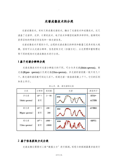
1基于光谱分辨率分类光谱成像技术针对光谱分辨能力的不同,可分为多光谱(Multi-spectral),高光谱(Hyper- spectral)以及超光谱(Ultra-spectral)。
多光谱的谱段数一般只有几十个,高光谱的谱段数可到达几百个,而超光谱一般指谱段数上千个。
它们的区别如表1所示。
表1多、高、超光谱的比拟分类分辨率通道数光谱典型例子多光谱〔Multi-spectral〕10-1λ量级5—30 ETM+ASTER高光谱〔Hyper-spectral〕10-2λ量级100—200AVIRIS超光谱〔Ultra-spectral〕10-3λ量级1000—10000GIFTS2 基于信息获取方式分类光谱成像仪需要对三维“数据立方〞进行探测,而现今的探测器最多能进行二维探测。
要想获得完整的三维数据,理论上至少需增加一维的空间扫描或光谱扫描。
光谱成像技术获取图谱信息的主要方式有:挥扫式(Whiskbroom )、推扫式(Pushbroom)、凝视式(Staring)以及快照式(Snapshot)。
挥扫式成像光谱仪的光谱成像系统只对空间中某点进行光谱探测,通过沿轨和穿轨两个方向扫描获取完整的二维空间信息,其信息获取方式如图1a所示。
A VIRIS就是通过挥扫成像[1]。
推扫式光谱成像系统探测空间中一维线视场(图1b中的X方向)的光谱,通过沿轨方向(Y方向)扫描实现二维空间信息的获取,芬兰国立技术研究中心实验室研制的AISA就是典型的推扫式成像光谱仪[2]。
环境词汇表
环境工程词汇安全阀safetyva1ve安全浮箱emergencyf1oatingcaisson安全闸emergencybu1khead板条式输送机s1atconveyor半反应ha1freaction半封闭水体semi-enc1osedwaterbody半水化物semi-hydrate半污水生物mesosaprobia饱和浓度saturationconcentration饱和溶解氧saturateddisso1vedoxygen保存性污染物conservativepo11utants保护格栅protectingrack 曝气器aerator曝气池aerationbasin曝气滴滤池aeratedtrick1ingfi1ter本底噪声backgroundnoise泵式挖泥机pumpdredger泵送量pumpde1ivery灌水器decanter比容积specificvo1ume比色测氧仪co1orimetricoxygendetector比声计acousticmeter表面力口速曝气acce1eratedsurfaceaeration表面曝气机surfaceaerator表面活性齐(Jinterfacia1activeagentBOD(生化需氧量)Biochemica1OxygenDemand不降解non-degradab1e不溶解物inso1ub1esubstance采滤器s1udgesamp1er初沉池primarysett1ingtank 初澄池pre1iminaryc1arifier初滤池primaryfi1ter除砂设备sande1iminator除油池greaseremova1tank除气器deaerator除氧器deaerator除污机c1eanerCOD(化学需氧量)Chemica1OxygenDemand 串联泵pumpsinseries串联质谱仪tandemmassspectrometer残渣量1eve1ofresidue槽桨式搅拌器trough-padd1emixer超声波液位计u1trasonic1eve1meter超声波流量计u1trasonicf1owmeter超声波液位开关u1trasonic1eve1switch沉淀池sedimentationtank沉淀滴定法vo1umetricprecipitationmethod沉淀(降)物foots,sett1ingmatters沉泥池mudsump沉砂池(箱)gritchamber 沉污池(沉淀池)wetpit沉砂池搅拌器gritchamberagitator沉箱sinkingcaisson废物处理wastedisposa1垃圾焚化装置refuseincinerator垃圾收集refuseco11ection热岛效应heatis1andeffect澄清池c1arificationtank澄清过滤c1arifyingfi1tration澄清器defecator持水当量moistureequiva1ent充水堰wasteweir冲砂闸sands1uice(unders1uice)冲砂闸门f1ushgate(wash-outgate)冲洗池rinsetank 抽水池primingreservoir出水阀out1etva1ve出渣槽s1agnotch吹泄阀(箱)b1ow-offva1ve(tank)垂直闸门堰draw-doorweir纯氧曝气法unoxprocess次漂浮生物hyponeuston次生环境secondaryenvironment粗格栅coarsescreen粗格栅井coarsescreenwe11粗滤池coarsefi1ter催化剂cata1yst萃取溶剂extractiveso1vent存水池dew-pondoi1ywatersewer含油污水separator分离器equa1izationbasin/ho1dingequa1ization平衡水池disso1ved-airf1otation溶气浮选aerated1agoon曝气池sandfi1ters砂粒过滤器eff1uent流出液neutra1izationpond中和池%so1ids固体百分率Part1 storm-waterretention雨水积池primaryc1arifier一次沉降池DO-disso1vedoxygen溶解氧量aeration曝气f1ow流量thickener增稠池secondaryc1arifier二次沉降池pressurefi1ter加压过滤器gravityfi1ter重力过滤器Part2Corrugated-p1ateinterceptor波纹板油水分离器s1udgepit污泥地out1et排出口adjustab1eout1etweir可调出口堰oi1Skimmer撇油器oi1g1obu1es油珠oi11ayer油层adjustab1ein1etweir可调入□堰sediment沉淀物sedimenttrap沉淀物捕集器Batch-sti11systemforrecoveryofwasteso1vents 回收废溶剂的间歇蒸储系统traptodrain疏水排水阀condensate冷凝水e1ectricsteamgenerator电热蒸汽发生器rupturedisk防暴膜packing填料coo1ingtower冷却塔co1d-watermakeup冷去t∣水补充co1d-waterrecyc1epump冷却水循环泵Strippingprocess汽提过程pressfi1ter压滤机vacuumfi1ter真空过滤机centrifuge离心机dewatering脱水residua1ch1orine余氯f1uegas烟气incinerator焚烧炉outfa11流出口s1udgepumpsuctionpipe污泥泵吸入管s1udge-co11ectinghopper集泥斗f1ightscraperchainsprocket舌IJ泥板链轮woodf1ights木制刮板rotatab1eoii1-skimmingpipe可旋转撇油管oi1-retentionbaff1e截油挡板eff1uentweirandwa11废水溢流堰板eff1uentf1ume废水槽fromwastewaterfeedtank来自废水料槽feed-bottomexchanger料液-塔底液换热器condenser 冷凝器decanter倾析器recoveredorganicch1oride回收的有机氯化物1.P.steam低压蒸汽strippedwater汽提工艺水stripper汽提塔Anactivated-s1udgesystem活性污泥系统tob1endingtank混合槽so1idswaste固体废弃物togritremova1移走砂粒wetwe11湿井aerationrecyc1e曝气循环fromaeration来自曝气池secondaryc1arifier二次澄清器secondaryeff1uent二次废水separator分离器hydrocyc1one旋液分离器centrifuge离心机todecantationtank去浅析槽gateva1ve闸阀g1obeva1ve截止阀;球心阀ang1eva1ve角接阀p1ugcock旋塞freeba11va1ve自由式球阀fixedba11va1ve固定式球阀ang1e1iftcheckva1ve角接式升降止逆阀diaphragmva1ve隔膜阀butterf1yva1ve蝶阀ti1ting-diskcheckva1ve斜盘式止逆阀专业辱用桐汇表A/O-anoxicandaerobicoxidation厌氧/好氧氧化AAS一atomicabsorptionspectrophotometry原子吸收光谱abiotic 非生物的ABS一a1ky1benzenesu1fonate 烷基苯磺酸abscissa 横坐标absorbance吸光度absorbate 被吸收的物质absorbent 吸收剂absorption吸收作用accessory 附件acc1imation 驯化accumu1ator 蓄电池acet- 乙酰,次乙基acetamide 乙酰胺acetate乙酸盐aceteny1 乙快基acetone丙酮acety1ene乙快acidimetry 酸量滴定法acry1ic 丙烯酸的activatedadsorption 活性吸附activateda1umina 活性氧化铝activatedcarbon活性碳activateds1udgeaeration活性污泥曝气activity活度acy1 酰基additive添加剂adiabatic绝热的adsorbent 吸附剂adsorption吸附作用adsorptionbar 吸附等压线adsorptionisotherm 吸附等温线adverse 不利的有害的,逆的adversecurrent逆流aer(o)- 空气,气体aerate曝气aeration曝气aerobic好氧的aeroge1 气凝胶aerogenicbacteria 产气菌aeroso1气溶胶affinity 亲和力agar琼脂agent试剂airbornedust 飘尘airborne 飞行在空中的,空降的--3.1 醛a1dehyde醛a1ga藻类a1gicide 除藻剂a1iphatic脂肪的a1ka1i碱阀门资料swingcheckva1ve旋启式止逆阀vartica11iftcheckva1ve直立升降式止逆阀wedgegate楔形闸板g1obetypedisc球心形阀盘ba11球体diaphragm隔a1ka1imeta1 碱金属anoxic缺氧的a1kane烷烽antifoamer 防沫剂a1kene烯煌apparatus 仪器a1ky1 烷基appurtenance[9,p91inθns]附属设备,附件a1ky1mercury 烷基汞aquatic 水生的a11y1 烯丙基aquifer蓄水层a1um 硫酸铝aquo- 水合-a1uminumsu1fate 硫酸铝argon 氤ambient周围的,环境的aromatic芳香的amide酰胺ary1 芳香基amine胺asbestos 石棉amino氨基aspha1t 沥青,柏油ammonianitrogen氨氮assay 化验,分析,检定ammonia-sodaprocess 氨碱法assimi1ate 同化ammonium钱(NH4+) atmospheric boundary[aetmθs,ferik]大气边界层amphoteric 两性的atmosphericdispersionmode1 大气扩散模式amy1- 戊基atomizer 雾化器amy1o1ysis 淀粉水解autoc1ave 高压釜amy1opectin 支链淀粉auto-exhaust机动车排气amy1ose 直链淀粉autopurification 自净作用anaerobic厌氧的autotrophic自养anaerobicdigestion 厌氧消化axia1-f1owpump 轴流泵ana1ysisvariance 方差分析azeotrope 共沸混合物ana1yticba1ance分析天平azeotropic 共沸混合物的-ane 烷(饱和)azide 叠氮化合物anhydride 酸酊azo- 偶氮基ani1ine苯胺azo-dye偶氮染料anionic阴离子的azotize 固氮anisotropic 各项异性的annu1ar 环形的Bbackextraction反萃取benzoic安息香酸的,苯甲酸的backup 支持,备用设备benzoxy- 苯甲酸基backwashing 反冲洗benzy1苯甲基baff1e挡板benzene 苯barrack粗格栅bicarbonate 酸式碳酸盐base 碱binary 二元的,二进制的basiccarbonate 碱式碳酸盐bio生物的-batch一次的分量,一批bioactivity生物活性beaker 烧杯bioassay 生物监定bench-sca1e小试的,小型的biochemica1生化的bentonite 膨润土bioconcentration生物富集benzo-苯并的biodegradab1e生物可降解的bio-disksystem 生物转盘break-pointch1orination[dnιri'nei⅛]折点加氯biofi1m生物膜brine盐水,海水bio1ogica1生物学的BTEX-benzene,to1uene,ethy1benzene,xy1enebiomass生物量['t□1jυi:!] [,zai1iιr] biooxidation 生物氧化苯,甲苯,乙苯,二甲苯bioremediation生物法恢复补救buffer缓冲,挡板biosphere生物圈bu1king膨胀biota 生物群bu1kings1udge污泥膨胀biotope 群落生境bumper 缓冲器biouptake生物吸收buret滴定管b1anktest 空白实验but- Tb1ower 鼓风机butane丁烷BOD-biochemica1oxygendemanc I生化需氧量buty1- 丁基boi1er锅炉by-product 副产物breakdown 细目分类Cca1ibrate标定,校准che1ant 螯合剂ca1ome1甘汞电极ch1orination 氯化作用capi11ary毛细管ch1orine['k1n:ri:] 氯capsu1e 容器,密封舱ch1oro 氯一caption 标题,说明ch1orobenzene 氯苯carbohydrate 碳水化合物Ch1orof1uorohydrocarbon氯氟烧carbo1ic(苯)酚的ch1oroform氯仿carbonmono(o)xide 一氧化碳Ca1orop1ast 叶绿体carbonaceous含碳的chromatography[,krθumθ,tυgrθfi]层析,色谱法carbony1默基cinder 煤渣,炉渣carboxy1竣基cis-顺-carboxy1ic竣基的c1arifier澄清池,澄清剂carcinogenic 致癌的c1ausprocess 克劳斯二级脱硫法cata1yst催化剂CMR-combinativemixedreaction完全混合式反应器cationic阳离子的coagu1ation凝结caustic苛性的coa1-tar 煤焦油cavernous 多孔的coating 涂敷,涂布ce1ite 硅藻土cocata1yst 助催化剂ce11u1ar 细胞的cock 考克,旋塞ce11u1ose 纤维素COD-chemica1oxygendemand化学需氧量centertakeoff 中心出水coefficient系数centrifuga1离心的coke 焦炭centrifuge 离心机co1dtrap 冷阱centripeta1向心的co1iform[,kn1ifn:m]大肠杆菌chainreaction链式反应co11aboration 合作,协作char 煤炭co11oida1胶状的charcoa1 木炭co1orimeter比色计comminution 粉碎contamination污染物common-ioneffect同离子效应contour轮廓线comonomer 共聚单体contractor 立约人compartment 部分,隔板,间隔coprecipitate 共沉淀compatibi1ity 兼容性corre1ate 相关competitiveadsorption竞争吸附corrode 腐蚀comp1ex 络合物corrosion腐蚀comp1exation络合作用counter 逆Comp1eximetric 络合滴定的countercurrent 逆流composite 合成物courier 信使compost 堆肥cova1ent共价的concentration浓度cracking 裂解concentrationso1ubi1ityproduct 浓度溶度积creso1甲酚condensation 冷凝criteria 标准conduit导管crucib1e土甘蜗conjugatedacid 共甄酸cryogenic[,kraiθdgenik]低温的conjugation共辗crysta1 晶体consecutivereaction连串反应crysta11ine 晶体的conservation 保存,守恒cu1ture培养液consistency 连贯性cure 硫化conso1e控制台,仪表板cyanide 氧化物constantratepump 恒流泵cyc1one旋风分离器constanttemperaturebath恒温浴cy1inder 汽缸constituent成分Ddataprocessing 数据处理di 二database 数据库dia1ysis渗析dec 癸diaphragm横隔膜deca 十diastase 淀粉酶decantation 倾析法diazo重氮基decibe1分贝diazosa1t 重氮盐deepshaftreactor 深井曝气dichromate[dai,krθumeit]重铭酸盐degenerate 退化,变质diese1柴油机,内燃机degrit除砂differentia1potentiometrictitration 差示电位滴定dep1ete耗尽[p9,te∏1fi,nmitik][ti,trei1⅛n]derivative衍生物diffraction衍射desiccation 干燥diffractionana1ysis 衍射分析destructivedisti11ation 干储diffuser扩散器detention 停留digestion 消化detergent去垢剂,清洁剂dio1efin二烯燃deteriorate 使恶化,损坏dioxins二恶英dew 露水dipo1emoment 偶极距dextrorotatory右旋光的directanodicstrippingvo1tammetry直接阳极溶出伏安法discrepancy 误差,偏差disti11ation蒸储discrete 离散的diurna1白天的disinfect消毒DO-disso1vedoxygen溶解氧disinfectant 消毒剂dosage 剂量disintegrator 粉碎机drainage排水设备disposa1处理、处置drop1et 微滴disso1ved-airf1otation 溶气浮选法dyes 染料EE.co1i.(escherichaco1i) 埃希氏大肠杆菌EPA-environmenta1protectionagency 环境保护局ebu11atingbed 沸腾床epoxy环氧的ECD一e1ectroncapturedetector电子捕获检测器epoxy 环氧基eco1ogy生态学equiva1ent等当量的ecosystem 生态系统erode 腐蚀eff1uent 出水erratic 不稳定的EIA-environmenta1impactassessment环境影响评价ester酯类e1ectrocapi11arity电毛细管现象-ester 酯e1ectro1yte 电解质esterification 酯化反应e1ectronegativity 电负性estuary['estjua] 河口e1ectromicroscope 电子显微镜eth- 乙e1ectro-osmosis电渗透ether酸e1ectrop1ate 电镀-ether 雁e1uant洗提液ethy1ene 乙烯empirica1 经验主义eutection 低共熔体的emu1sion乳化液eutrophic 富营养化的encapsu1ate 密封eutrophication 富营养化endo- 内_evaporation 蒸发作用endogenous内源的exchangeadsorption交换吸附endrin异狄氏剂excreta 排泄物-ene 烯exothermicity放热性ennea 九个一组exponent 指数entha1py[en'θae1]] 焰extendedaeration延时曝气entropy[,entrθpi] 燃extrace11u1arenzyme胞外酶environmenta1hormone环境激素extraction萃取enzyme[,enzam]酶extrapo1ation 外推法Ffaci1ities 设施ferrous亚铁的factoring 因式分解fi1amentous丝状菌facu1tative兼性的fi1trate过滤,滤液ferri- 铁-fi1tration 过滤ferric三价铁f1ake薄片ferrite 铁素体f1amespectrophotometry 火焰光度法ferro-亚铁-f1ap 活盖,活板f1ask烧瓶forma1in福尔马林f1ex 软管formic甲酸的f1occu1ation絮凝fossi1 化石f1otation 气浮fractionation 分储f1owrate流量,流速freeswimmingci1iates 游泳型纤毛虫f1ue-gasdesu1furization 烟气脱硫Freon 氟利昂f1uffy 松散的front-pane1 面板f1uidizedbed 流化床frothing 起泡f1uoride 氟化物FRP-fiberg1assreinforcedp1astics 玻璃钢Auorimetry 荧光剂fugacity 逸度f1uorine 氟fu11-sca1e 实际尺寸,大规模的f1ush 冲洗fume 难闻的气味,烟熏fo1iage 植物,树叶fungi 真菌forma1dehyde甲醛fungicide 杀菌剂GGAC一granu1aractivatedcarbon颗粒活性炭g1ycero1甘油,丙三醇ga1actose 半乳糖granu1ar 颗粒状的ga1vanometer1gaeIVSiwmita]检流计granu1ometry 粒度分析gasifier气化器grating 光栅,格栅GC/MS一gaschromatography/massspectrometry grave1 砾石[krθmθ,t□grθf j色质联用gravimetric 测定重量的ge1 冻胶,凝胶greenhouseeffect温室效应generic 属的,类的grit 粗砂geotherma1stream 地热流gunite 水泥砂浆层g1ucose['g1u±θus]葡萄糖Hha1ide卤化物hex 巳ha1o卤-hexa 六ha1ogen卤素hinder 阻碍handbook 手册hood 通风橱hazardous危险的hopper漏斗head1oss水头损失hose 胶管heatcapacityatconstantpressure等压热容HP1C—highperformance1iquidchromatography高压液相色谱heatcapacityatconstantvo1ume等容热容HRT-hydrau1icretentiontime水力停留时间he1ica1 螺旋的humus腐殖质he1ica1agitator 螺旋式搅拌器hybridism杂化的hept 庚hydration水合作用hepta 七hydrau1ic水力的herbicide 除草剂hydro氢化的hetero 杂_hydrocarbon½heterogeneity不均匀性,异相性hydroch1oricacid 盐酸heterotrophic异养的hydro1ysis水解hydrophi1ichydrophobic hy droso1hydrostatichydroxide hydroxy1-亲水的疏水的水溶胶流体静力学氢氧化物羟基-hygroscopichyperbo1a hypo-hypoch1orite hypothesis吸湿性双曲线次一次氯酸盐假设I-icanhydride 酸酊instrumenta1ana1ysis仪器分析IC一ionchromatography[krθmθ,t□gre]离子色谱intake 摄入量imhoff双层的intermittent间歇式的-imide 酰亚胺intrace11u1arenzyme胞内酶-imine亚胺intrinsic内在的immobi1ize 使不动inventory清单,目录immobi1izedenzyme固定化酶iodine 碘impe11er叶轮ion离子insitu现场ionexchanger离子交换剂incidence 发生率ionpair 离子对incinerate焚烧IP-inha1ab1epartic1e可吸入颗粒物incubation培养iso- 异-indicator指示剂isobuty1- 异丁基inert 惰性isomer 同分异构体inertia[i'na:月惯性isopiestic等压的inf1uent进水isopropy1异丙基inha1ab1e可吸入的isotope同位素inhibit约束,抑制isotropy各向同性的insecticide 杀虫剂iterativemethod 迭代法Jjack 千斤顶ketoneK酮kinetic[kai,netik]动力学的11actic乳酸的1eanphase贫相1actose 乳糖1evorotatory 左旋光的1agoon氧化塘1iftpipe 提升管1aminar层流的1ignin木质素1andfi11填埋1ime石灰1AS一1ineara1ky1benzenesu1fonate线形烷基苯磺酸1imestone 石灰石1athe 车床1iner衬里1attice 晶格1itmus 石蕊1eachate渗出液1oading负荷1ogarithmic 对数的Iyophi1ic 亲液的1PG一1iquifiedpetro1eumgas液化石油气Iysimetric 溶度的Mmanifo1d歧管methy1-甲基的marshgas 沼气microorganism 微生物massba1ance 物料守恒microscreening 超滤membrane膜M1SS-mixed1iquorsuspendedso1id混合液中的悬浮固体mercaptan 硫醇M1VSS一mixed1iquorvo1ati1esuspendedso1id混合液中的挥发性悬浮颗粒物mercury[,m3kjur j汞moiety 部分,半个meteoro1ogica1[mi:t Bre1Od3k(e)1] 气象学mo1a1ity(重量)摩尔浓度mesosca1e 中间尺度mo1arity (体积)摩尔浓度meta 偏-,间位mo1ecu1aradsorption 分子吸附metabo1ism新陈代谢moment 矩meta11urgica1 冶金学的mono 单metasi1icate 硅酸盐monomer 单体metastab1e 亚稳态的monophase 单相的metathesis 复分解作用moving-bedreactor 移动床反应器meth-甲municipa1市政的methane甲烷mutagenicity 诱变性methodo1ogy 方法学MW一mo1ecu1arweight分子量Nn-正nitrogendioxide二氧化氮naphtha1ene['naefθe1i:n]蔡,卫生球nitroso- 亚硝基-naphthene环烷烧NMHC一non-methanehydrocarboncompounds非甲烷总燃NDIR-nondispersiveinfraredmethod非分散红夕卜法NMR-nuc1earmagneticresonancespectroscopy核磁共振nebu1ous[,nebjo1θs]模糊的nocturna1[nnk,tθinθ1]夜晚的neuston 漂浮生物nomenc1ature 术语nitrosation 亚消化作用non 壬-nitri1e月青norma1ity当量浓度的,正态性nitrite亚硝酸盐nuc1eophi1ic亲核的nitro硝基-oct辛o1eophobic疏油的octa 八o1factory 嗅觉octanenumber 辛烷值-one 酮odor 气味on-1ineana1ysis 在线分析off-gas 废气on-site在场的,就地的off-1ine离线的ORP-oxidationreductionpotentia1氧化还原电位oi1refining 炼油,石油精制ortho-原,邻位-o1醇orthogona1[n:'θngθn1]直角的o1eophi1ic亲油的OTE一oxygentransferefficiency 氧传输效率OUR一oxygenuti1izationrates氧禾U用率oxidase 氧化酶outfa11 排水口oxidation 氧化作用overdraft透支-oxide 氧overf1ow溢流oxygensagcurve氧垂曲线oxa 氧杂-oxygentransfercoefficient 供氧系数oxa1ate 草酸盐-oy1 酰oxa1icacid 草酸ozonedep1etion[,ΘUZΘUΠ]臭氧耗竭oxidant 氧化剂ozonization臭氧化Ppacking填料phosgene 光气PAC一poweractivatedcarbon,po1ya1uminumch1oride phosphate 磷酸盐粉末活性炭,聚合氯化铝phosphite 亚磷酸盐padd1e 浆phosphoricacid 磷酸PAH—po1ycyc1icaromatichydrocarbons多环芳燃phosphorus 磷PAM—po1yacry1amide 聚丙烯酰胺photo光_PAN-peroxyacety1nitrate过氧硝酸乙酰脂photochemica1smog光化学烟雾paperpu1p 纸浆photoe1ectric 光电的para对-,仲-photo1ysis光解paraffin烷烧,石蜡photosensitive 光敏化particu1ate 颗粒物photosynthesis光合作用pathogenic[,paeθθ,dgenik]致病的phreaticpump[fri,aetik]潜水泵PCB—po1ych1orinatedbipheny1多氯联苯phtha1ate 邻苯二甲酸盐pent 戊physicochemica1物理化学的penta 五phytop1ankton浮游植物peptide肽化合物pigment 颜料,色素per 过-pigmentedf1age11ate 有色纤毛虫perco1ate渗透液pi1ot-sca1e 中试perco1ation 渗透pinene松菇,源烯perforatedp1ate 多孔板pipe1ine 管道perista1ticpump 蠕动泵pistoncompressor活塞压缩机permeate[,pθimieit]渗透Pit 坑,斗peroxide过氧化物p1ankton浮游生物peroxy过氧-p1asma等离子体pesticide农药p1astifier 增塑剂petro1eumether 石油酸p1ateheatexchanger 板式换热器PFC-po1yferricch1oride 聚合氯化铁p1ate-and-framefi1terpress板框压滤机PFR―p1ugf1owreactor活塞流反应器p1ug-f1ow推流pharmaceutica1[fα:mθ'su:t k(θ)1]制药的,药学的PM-particu1atematter 颗粒物phasechange 相变pneumatic气动的pheno1酚类po1arography 极谱法pheno1ic[ι,nn1ik]酚的po1y 聚_pheno1icresin 酚醛树脂po1yacry1amide 聚丙烯酰胺pheny1苯基po1ycondensation 缩聚作用po1ycyc1ic多环的Probati1istic 概率的po1yester 聚酯proceeding 会刊,科研报告集po1yether 聚酸processingwastewater 工艺废水po1ymer 聚合体prop 丙po1ymeric聚合的prope11er 桨po1yo1 聚合体propiny1 丙快基po1ysaccharide[p□11saekθra] 多糖prototype 原型,样品po1yurethane[,pn1i,juriθein]聚氨酯protozoan原生动物porce1ain[,pnιs1in]瓷,瓷器pseudo- 伪的porosity空隙性,多孔性pseudo-firstorder伪一级反应porous 多孔的PU1P 纸浆potab1e可饮用的pumphead泵压头potassium[pθ,taesDm]钾pump1ift泵扬程ppb-partperbi11ion十亿分之一PVC—po1yviny1ch1oride 聚氯乙烯ppm-partpermi11ion百万分之一pyrene 花ppt~~partpertri11ion万亿分之一pyrex 硼硅酸玻璃pressurization 加压pyridine 喀咤primary伯的pyro1ysis[pai,rn1isis]热解prism 棱镜Qqua1itative定性的quasi准quantitative定量的quaternary季的,四元的Rradia1 径向refractory难降解的radia1f1owtank 辐流式沉淀池refuse 垃圾,废物radon氨regeneration 再生raffinate萃余液regu1atory 调节的rainout雨洗re1uctance 磁阻rake耙rep1ica 复制品,拷贝raschingring 拉西环residua1ana1ysis[,rezidju:1]残差分析ratedhorsepower 额定功率resin树脂RBC—rotatingbio1ogica1contactor生物转盘retention 保留,停留reagent试剂reversionextraction 反萃取reca1citrant难降解的RFC-reinforcedconcrete钢筋混凝土recess 凹槽rheo1ogy friι,n1θd3i]流变学reciprocating往复的rheo1ogica1 流变的crysta11ization 重结晶rimtakeoff四边出水rectify 精储risings1udge污泥上浮reductase还原酶rootsb1ower罗茨鼓风机reductiongearbox 减速齿轮箱rotifers 轮虫ref1ux 回流runoff地表径流saccharide[,saekθraid]糖类so1ub1e可溶的sa1icy1ic 水杨酸的so1ute 溶质sa1icy1icacid 水杨酸so1vent溶剂sa1inity[sθ,1initi]含盐量SOOt 烟黑sa1tingout 盐析sorption吸着saponification 皂化sparepart备件sarcodina 肉足纲spatia1 空间的saturated[saet⅛reitid]饱和的speciation 形态分析SBR—sequentia1batchreactor序批式反应器spectrophotometer分光光度计scour[,skauθ]冲刷spectrum 光谱scraper刮泥机spent 剩余的,废液screening滤余物,格栅spherica1va1ve[,sferik1]球阀scrub洗涤spira1-f1ow 螺旋流scum[sk∆∏ι]泡沫sta1kedci1iates 柄纤毛虫sea1 密封剂standarddeviation 标准偏差seam 缝,接缝starch 淀粉secondary仲的stearic硬脂的sedimentation沉淀stereoisomer 立体异构体separation分离steri1e[s,terθ1]无菌的septictank化粪池stoichiometric 化学当量的sett1e沉降strappingpump 计量泵sewage[,sjuddζ∣污水,下水道stratification[,straetifi,kei⅛]成层作用sewer下水道stratosphere平流层sewerage污水工程,排水工程stripping气提shear剪切力strongso1ution 浓溶液sheath[J:θ] 外皮,外罩styrene苯乙烯shock1oad 冲击负荷sub1imate 升华sieve筛substrate基质si1icage1 硅胶Su1fani1ic 苯磺酸的si1t淤泥su1fate硫酸盐sink污水坑,洗涤槽,贮水池su1fite亚硫酸盐siphon 虹吸su1furic硫酸的skimmer撇沫器su1furous亚硫酸的s1ime粘泥sump 贮槽,污物贮存器s1it 窄缝surfaceaerator 表面曝气器s1udge污泥surgetank 缓冲罐s1ug 冲击,强击suspended 悬浮的s1urry 泥浆,粘泥,淤泥SVI一s1udgevo1umeindex 污泥体积指数sodium[sθudiθm]钠symposium[sim,pθuziθm]专题讨论会so1ubi1ityproduct 溶度积syndet合成洗涤剂synthesize 合成tandem串联titaniumdioxide二氧化钛taper渐减的/锥形,锥度titration滴定taperaeration渐减曝气TKN 总凯氏氮Te1fon 聚四氟乙烯TOC一tota1organiccarbon总有机碳tempora1 暂时的,时间的to1uene[?1joi:n]甲苯teratogenicity 致畸性toxicity[tnk,sisiti]毒性tertiary叔的transmittance 透光度tetra- 四transpiration 蒸腾tetrach1oride 四氟化物treatment处理therma1热的tri- 三therma1decomposition热分解tricking滴流的therma1resistance 热阻trio1 三元醇thermistor 热敏电阻,温度计trophicity营养度thermocoup1e热电偶troposphere对流层thermodynamic[θθimθudai,naemik]热力学的trough槽thermo1ysis 热分解turbidimeter 浊度计thio 硫代turbidity浊度thiosu1fate 硫代硫酸盐UUASB-upf1owanaerobics1udgebed u1trasonic超声的上流式厌氧污泥床u1travio1et紫外线u1trafi1tration 超滤urea尿素Vva1ve[vae1v]球形阀VOC-vo1ati1eorganiccompounds挥发性有机物va1vetray 浮阀塔板voidfraction空隙率varnish 清漆vo1ati1e挥发性的Venture文丘里vo1umetricf1ask 容量瓶viny1 乙烯基vortex漩涡,涡流viscometer 粘度计vu1canize[,v∆1kθnaκ]硫化vitreous[,vitriθs]玻璃状的,透明的WWAO——wetairoxidation湿式空气氧化wedge 楔形warehouse 仓库weightedaverage 加权平均值washout洗脱weir堰watershed水域wormcondenser 旋管冷凝器weakacid 弱酸Xxeroge1 固溶胶xy1ose木糖xy1ene[,zai1iιr] 二甲苯两性离子yeast酵母Y-ynezeo1ite[⅛iiθ1ait] zoog1oea 沸石菌胶团Zzwitter-ion。
英文翻译-运用于机场多普勒天气雷达的移动杂波频谱滤波器

成都信息工程学院毕业设计英文翻译运用于机场多普勒天气雷达的移动杂波频谱滤波器系别电子工程学院姓名杨杰专业电子信息工程班级大气探测2班学号2007021206Moving Clutter Spectral Filter for Terminal DopplerWeather Radar1.INTRODUCTIONDetecting low-altitude wind shear in support of aviation safety and efficiency is the primary mission of the Terminal Doppler Weather Radar (TDWR). The wind-shear detection performance depends directly on the quality of the data produced by the TDWR. At times the data quality suffers from the presence of clutter. Although stationary ground clutter signals can be removed by a high-pass filter, moving clutter such as birds and roadway traffic cannot be attenuated using the same technique because their signal power can exist anywhere in the Doppler velocity spectrum. Furthermore, because the TDWR is a single-polarization radar, polarimetry cannot be used to discriminate these types of clutter from atmospheric signals.The moving clutter problem is exacerbated at Western sites with dry microburst, because their low signal-to-noise ratios (SNRs) are more easily masked by unwanted moving clutter. For Las V egas (LAS), Nevada, the offending clutter is traffic on roads that are oriented along the radar line of sight near the airport. The radar is located at a significantly higher altitude than the town, improving the visibility to the roads, and giving LAS the worst road clutter problem of all TDWR sites. The Salt Lake City (SLC), Utah, airport is located near the Great Salt Lake, which is the biggest inland sta ging area for migrating seabirds in the country. It, therefore, suffers from bird clutter, which not only can obscure wind shear signatures but can also mimic them to trigger false alarms. The TDWR “dr y” site issues are discussed in more detail by Cho (2008).In order to mitigate these problems, we developed a moving clutter spectral filter (MCSF). In this paper we describe the algorithm and present preliminary test results. 2.THE PROBLEMFigure 1 illustrates one of the difficulties with not filtering out moving clutter signals from TDWR data. A widespread coherent bird flight event like this has two of the characteristics of a microburst-outflow of heightened reflectivity away from a central source and velocity divergence along the radials. Thus, a microb urst detector is in danger of issuing a false alert in this case.Figure 2 shows Doppler velocity spectra vs. range for a microburst event (left) and a case with birds in many different range gates (right). Not only are there bird signatures that are isolated in range-Doppler, there is a feature in range gates ~40-50 that is quasi-continuous and looks similar to a strong wind shear. The challenge is to filter the bird signals in the right-hand case but not the microburst in the left-hand case.Figure 1 Example of bird clutter observed with the SLC TDWR at 0.5° elevation.Left panel shows reflectivity, right panel shows radial velocity.Figure 2. Doppler velocity spectra vs. range for a microburst case observed with the Program Support Facility (PSF) TDWR in Oklahoma City, OK at 0.3°elevation (left), and a widespread bird contamination case observed with the SLC TDWR at 0.5 elevation (right).Bats can also cause similar problems for radar wind shear detection when theyleave their roosts en masse at dusk.Road and rail traffic are also sources of moving clutter. In this case, the range-azimuth cells affected are known a priori, so the current method of dealing with the problem is to periodically generate a clutter residue map (CREM) and then censor the base data where the reflectivity does not exceed a certain amount over the CREM reflectivity. The LAS road clutter problem is shown in Figure 3. Note that some of the clearest road echoes line up with the radar line-of-sight radials. This phenomenon is also observed at other sites, and we call it the building canyon effect. In an urban environment roads are lined with buildings, so traffic is often not visible to the radar unless the beam shoots down along the road itself.Figure 3. LAS road clutter at 0.8°elevation. Left panel shows reflectivity, right panel shows radial velocity. The large wedge of blank reflectivity to the northeast of the radar is due to terrainblockage.Airplanes, of course, are also moving clutter. Because they are isolated targets, a point target filter deals with them effectively. Although the current operational algorithm merely censors these points, we plan to interpolate the base data across these points in the next major radar data acquisition (RDA) system software revision. The filtering algorithm presented in this paper should be an even better solution in the future.Finally, there are other moving targets that appear in TDWR data such as sea clutter and the spinning blades of a wind power turbine. The latter is expected to be an ever-growing source of clutter that is still in search of a solution. The work presented inthis paper does not specifically address these phenomena, as the focus has been on the data quality issues at SLC and LAS.3.MOVING CLUTTER SPECTRAL FILTERStationary clutter filters are typically applied on one range-azimuth dwell data at a time. Recognizing that more contextual information is necessary to identify moving clutter, techniques were developed that utilize multiple range gates of data. The point target filters employed on both the TDWR and the Weather Surveil-lance Radar-1988 Doppler (WSR-88D, more commonly known as NEXRAD) look for targets with reflectivity much higher than the neighboring range gates. This type of filter can remove aircraft and isolated avian signals, but the weather returns in the same cells are also lost.A more modern approach filters data in the two-dimensional (2D), Doppler velocity spectrum vs. range, domain (e.g., Sasaoka 2003; Meymaris 2007). Because moving clutter spectral signals tend to be spectrally compact and discontinuous in range, these techniques would look for a range-continuous signal (weather) and discard other spectral components (clutter). (Of course, stationary ground clutter can also be continuous in range, so it would have to be filtered out first.) Two drawbacks to this approach are that it is computationally intensive relative to traditional weather radar signal processing, and that the output base data are smoothed in range.With the development of a new RDA system (Cho et al.2005), which is currently running operationally at LAS and SLC, there is considerable spare computational capacity for the implementation of future algorithms. The scalable architecture easily allows for additional (and/or upgraded) central processing units (CPUs) to be installed to meet further computational demand. With regard to the second drawback of the existing 2D spectral processing approach for moving clutter filtering, spatial smoothing of the data runs counter to the T DWR’s mission of detecting wind shear. This is th e reason why we decided to develop our own moving clutter spectral filter for the TDWR.First, we will give a brief outline of the MCSF algorithm, and then delve into more details.To set up the processing environment, we form a Doppler velocity power spectrum at each range gate with the usual window-and-DFT approach. These spectra are stored in a 2D matrix (Figure 2, right). The following steps are then followed.1) Remove stationary ground clutter with the spectral filter of choice (Figure 5).2) Remove positive power anomalies along range at each spectral bin in a manner similar to a point target filter (Figure 6). Clutter signals that are not continuous in range are removed in this way.3) After suitable data massaging, determine the number and location of spectral modes (statistically significant peaks) at each range gate. A measure called the normalized circular excess mass (NCEM) is used to winnow out "insignificant" peaks in the spectra.4) Select one mode at each range gate such that the path connecting the modes has the shortest possible overall distance (Figure 7). This process favors retaining globally continuous (in range) signals over only locally continuous features. The assumption is that atmospheric signals will be continuous over longer ranges than moving clutter features.Figure 5. Stationary ground clutter is removed Figure 6. Isolated spectral peaks are removed from the spectra shown in Figure 2, right. from the spectra shown in Figure 5.5) For modes other than the ones selected by the shortest connecting path, reducethe number of "extra" modes using a stricter NCEM threshold. This step is needed to reduce the incidence of these "extra" modes being part of the atmospheric spectrum.6) Any leftover "extra" modes are deemed to be moving clutter and are removed by filling in with the computed spectral "noise" floor (Figure 8).7) Carry on with the rest of the usual signal processing for base data generation.Let us now elaborate on each step. (Note: The term "circular" used in this paper refers to the fact that the Doppler velocity spectrum aliases, or wraps around, at the end points.)There is nothing special about the first step of stationary clutter filtering. One of various different techniques can be used. However, note that the Gaussian model adaptive processing (GMAP) filter (Siggia and Passarelli 2004) assumes the absence of spectral signal other than a stationary ground clutter peak and a Gaussian weather component. Therefore, the presence of moving clutter signals distorts the weather moment estimation and can spuriously widen the "weather" spectrum within the filled ground clutter gap. We, thus, recommend against the use of Gaussian fitting and clutter-gap filling in the suspected presence of moving clutter.The isolated spectral peak filter in step 2 is similar to the TDWR point target filter, except that it runs along each spectral bin vs. range, and the number of neighbors considered in the spectral dimension expands with range away from the range gate of interest. This expansion prevents filtering of cases where the spectralrange signature has a shape like "\" "/" ">" or "<". So only features shaped like "—" or "·"are filtered. To be more specific, at range gate i and spectral index j, compare the spectral power P(i,j) to PP(i-m,j) and PP(i+m,j), and mark P(i,j) for removal if it is stronger than both PPs by a threshold T(m). The gate difference m goes from 1 to 3, and the threshold values used currently are T(1) = 8 dB, T(2) = 10 dB, and T(3) = 17 dB. Removal is accomplished by linear interpolation over range. PP is the peak value of spectral power taken over bins j-n to j + n (circularly wrapped around to the other side of the spectrum if needed). As stated earlier, this spectral neighborhood expands with range such that n = 2 for m = 1, n = 4 for m = 2, and n = 6 for m = 3.In step 3, in order to avoid identification of spurious spectral peaks as modes, we first smooth the spectra over the spectral bins. For this purpose we use a Gaussian kernel of width 0.3NDFT/(2v a), where NDFT is the number of DFT bins and v a is the Nyquist velocity. We also perform a three-point triangular moving average over range;this minimal smoothing is the only averaging that we do in the range dimension. Then we estimate the spectral noise floor (power per bin) (e.g., Hildebrand and Sekhon 1974).Now, for a spectrum at a range gate, we locate all the local maxima. Then for each maximum, we compute the NCEM. The excess mass is essentially the area under the peak bounded by the curve itself and a horizontal-line lower limit defined by the highest value taken from the following set-either of the neighboring minima or the spectral noise floor. (If a local maximum is below the noise floor, it is deleted from the maxima list.) A nice visual illustration of the excess mass is given in Figure 2 of a paper by Fisher and Marron (2001). NCEM is the excess mass divided by the per bin spectral noise power, with the distribution curve wrapping around at the ends.Figure 7. Spectral modes (white dots) are Figure 8. Undesirable spectral modes are identified at each range gate, and the shortest eliminated .The first moment (white line) path (white line) connecting them in range is. is shown for reference.determinedLocal maxima with NCEM below a threshold (currently 5 dB) are eliminated. Elimination of a maximum expands the size of a neighboring mode, so the NCEMs arerecalculated for the remaining maxima. The process of NCEM computation and maxima elimination is repeated until no more reduction takes place. The remaining modes are deemed to be significant. Finally, the pointers to the modes are adjusted to be at the center of mass of the modes, not at the peaks.In step 4, one mode at each range gate is selected such that the path connecting the modes has the shortest possible overall distance from the first to the last gate. If there is no mode in a range gate, that gate is skipped. "Distance" is defined to be α(△i)2 +(△j)2, where △i is the range gate difference,△j is the circular difference in spectral bin numbers between modes, and αis a constant determining the relationship between range distance and spectral bin distance. Currently αis set to one; however, the algorithm is not very sensitive to α.The shortest overall path is determined using Dijkstra's method (Dijkstra 1959). We want the endpoints to have only one mode, so if an endpoint has more than one mode, we compute the circular median (Fisher 1993) of the mode locations over ten range gates from the endpoint and select the mode closest to the median.In step 5, we attempt to consolidate the spectral modes that are not part of the shortest path. The reason for doing this is that the initial mode detection process allows for fairly minor modes to be kept, and thus the weather spectrum may be tagged with more than one mode. We want it to be tagged with only one mode so that the final mode elimination step will not erode the weather spectrum. To do this, we repeat the mode identification process of step 3, but with the NCEM threshold raised to 20 dB and the mode that is part of the shortest path protected from elimination.Finally, in step 6, the modes that are not part of the shortest overall connection path are eliminated by filling them in with the spectral noise floor power.4.RESULTSWe now present some initial testing results of the MCSF algorithm. Figure 9 is a case from SLC where widespread bird flock flights contaminated the data. The upper two plots show the results without MCSF, and the lower two plots show the corresponding results with MCSF. The filtering works very well in this case, and we have many other examples of bird clutter that are cleaned up by MCSF in a similar fashion, albeit with small amounts of unfiltered moving clutter in some instances.Figure 9. Reflectivity (left) and radial veloc ity (right) plots for data processed without MCSF (top) and with MCSF (bottom). This was a bird clutter case observed with the SLC TDWR at 0.5°.Of course, the ability to filter out moving clutter is worthless to the TDWR if wind shear events are also removed or altered. Figure 10 shows a microburst without (top) and with (bottom) MCSF. There is very little change between the two processed results, and MCSF preserves the strong velocity gradients. MCSF also does well on a few other wind shear cases that we have collected so far, but we are in the process of capturingmany more cases for testing.Figure 10. Reflectivity (left) and radial velocity (right) plots for data processed without MCSF (top) and with MCSF (bottom). This was a microburst observed with the PSF TDWR at0.3°elevation.The results for road clutter were only partially successful, with MCSF filtering out traffic returns from roads that were not parallel to the radar line of sight. The roads that lined up with the radar radials, however, were largely not filtered. MCSF fails in these cases, because the moving clutter extends continuously in range for longstretches at a time. Thus, MCSF is not a complete solution for road clutter, but it should reduce the size of CREM areas where roads currently force data censoring.5.SUMMARY DISCUSSIONWith the introduction of a new open and scalable RDA to operational TDWRs, enhanced signal processing algorithms can be successively implemented to improve data quality. The first RDA algorithm upgrade focuses on mitigating range-velocity ambiguity (Cho et al. 2005). Dubbed Build 2 (emulation of the legacy processing algorithms is Build 1) it is currently undergoing acceptance testing by the FAA. The MCSF algorithm discussed in this paper may be part of a subsequent software upgrade (Build 3).There is still considerable testing and development that needs to be conductedbefore MCSF is deemed acceptable for operational use. For example, MCSF has only been tested on moving clutter with Build 1 data, which uses the legacy transmission scheme of constant pulse repetition interval (PRI) and pulse phase. Starting with Build 2, the transmission scheme will become more complex, with a mix of various multiple PRI and pseudorandom phase-code processing techniques. On surface scans, which are used for wind-shear detection and where MCSF will be most needed, the default mode will be phase-code processing with the PRI changing every dwell. Therefore, the interaction of MCSF with the phase-code processing, which also takes place in the spectral domain, needs to be investigated and the results optimized. There are other new processing features in Build 2 that need to be tested together with MCSF. However, the collection of Build 2 data at the problematic sites (SLC and LAS) awaits the acceptance and operational fielding of Build 2. So for now, we are only able to investigate MCSF-Build 2 interaction using data from the non-operational radars in Oklahoma City, where the moving clutter problem is not nearly as severe as in SLC and LAS.Due to the simultaneous processing of spectra across many range gates, the real-time implementation of this algorithm may require changes to the RDA software architecture, which is currently designed to process chunks of range gates in parallel. The computational load will also increase significantly, so it must be determined whether the present CPUs will be able to keep up or whether a hardware upgrade would be needed.MCSF is certainly not foolproof. If there is no underlying weather signal, it will not be able to filter out the moving clutter. If the 2D spectral-range signature of the moving clutter extends continuously over a long range, MCSF may select to preserve it instead of the weather signal. As we have seen, roads that run parallel to the radar line of sight will not be filtered well. However, the testing so far shows that it can dramatically improve the base data quality during periods when the current signal processing algorithm fails to do anything with moving clutter. As long as it is proven to be robust against the degradation of wind shear information, it would be a valuable addition to the TDWR arsenal in fighting moving clutter.6. ACKNOWLEDGMENTI would like to thank Amrita Masurkar for implementing and evaluating theSasaoka and Meymaris algorithms. I would also like to thank Mike Donovan for identifying test cases, Rich Chafe (SLC) and Pat Hinkle (LAS) for collecting the data, and Jeff Simpson and Robert Schaefer for assistance with data handling.运用于机场多普勒天气雷达的移动杂波频谱滤波器1.引言机场多普勒天气雷达(TDWR)探测低空风切变是保障航空安全和有效的主要任务。
- 1、下载文档前请自行甄别文档内容的完整性,平台不提供额外的编辑、内容补充、找答案等附加服务。
- 2、"仅部分预览"的文档,不可在线预览部分如存在完整性等问题,可反馈申请退款(可完整预览的文档不适用该条件!)。
- 3、如文档侵犯您的权益,请联系客服反馈,我们会尽快为您处理(人工客服工作时间:9:00-18:30)。
An Airborne A-Band Spectrometer for Remote SensingOf Aerosol and Cloud Optical PropertiesMichael Pitts, Chris Hostetler, Lamont Poole, Carl Holden, and Didier RaultNASA Langley Research Center, MS 435, Hampton, VA 23681ABSTRACTAtmospheric remote sensing with the O2 A-band has a relatively long history, but most of these studies were attempting to estimate surface pressure or cloud-top pressure. Recent conceptual studies have demonstrated the potential of spaceborne high spectral resolution O2 A-band spectrometers for retrieval of aerosol and cloud optical properties. The physical rationale of this new approach is that information on the scattering properties of the atmosphere is embedded in the detailed line structure of the O2 A-band reflected radiance spectrum. The key to extracting this information is to measure the radiance spectrum at very high spectral resolution. Instrument performance requirement studies indicate that, in addition to high spectral resolution, the successful retrieval of aerosol and cloud properties from A-band radiance spectra will also require high radiometric accuracy, instrument stability, and high signal-to-noise measurements. To experimentally assess the capabilities of this promising new remote sensing application, the NASA Langley Research Center is developing an airborne high spectral resolution A-band spectrometer. The spectrometer uses a plane holographic grating with a folded Littrow geometry to achieve high spectral resolution (0.5 cm-1) and low stray light in a compact package. This instrument will be flown in a series of field campaigns beginning in 2001 to evaluate the overall feasibility of this new technique. Results from these campaigns should be particularly valuable for future spaceborne applications of A-band spectrometers for aerosol and cloud retrievals.Keywords: Aerosols, clouds, climate, A-band, remote sensing1. INTRODUCTIONAerosols and clouds exert an enormous influence on the Earth’s solar and thermal radiation budgets and only through a detailed understanding of their role in the climate system will reliable climate simulations be possible. In fact, recent assessments of global climate change by the National Research Council1 (NRC), the Intergovernmental Panel on Climate Change2 (IPCC), and NASA agree that the largest uncertainties in our ability to predict future climate change are associated with the radiative effects of aerosols and clouds. These large uncertainties are, in part, due to a limited knowledge of the optical properties of aerosols and clouds on a global scale. A myriad of new sensors and satellite missions is currently being planned to aggressively pursue answers to this major question confronting credible prediction of climate change. However, as noted by the NRC1, these new measurements may not possess sufficient accuracy to significantly improve predictive capability.A promising new approach for spaceborne aerosol and cloud remote sensing is the retrieval of aerosol and cloud optical properties from high spectral resolution measurements of reflected sunlight in the oxygen A-band. Although the oxygen A-band has been utilized for a wide variety of remote sensing studies in the past, these studies were primarily focused on the retrieval of cloud top pressure3,4 or surface pressure5,6. O’Brien and Mitchell7 were among the first to recognize that measurements of reflected sunlight within the O2 A-band also contain information on the scattering properties of the atmosphere. This study suggested that the information on the optical properties of aerosol or cloud scattering layers is embedded in the detailed line structure of the O2 A-band, but will only be observable by very high spectral resolution instruments. Recently, Stephens and Heidinger8 developed the theoretical foundation for retrieval of aerosol and cloud optical properties from high-resolution spectral measurements of O2 line absorption. In a related paper, Heidinger and Stephens9 proposed a conceptual approach for retrieval of aerosol and cloud properties from a spaceborne A-band instrument. These two companion studies demonstrated the potential of high spectral resolution A-band spectrometers for the determining the optical properties of scattering layers, such as aerosol or cloud optical depth, aerosol single scatter albedo, and cirrus cloud asymmetry parameter. These conceptual studies, however, argued that a spectral resolution of at least 1 cm-1 would be necessary to extract the desired aerosol and cloud particle information from the A-band measurements. This required spectral resolution is significantly higher than exists in current spaceborne A-band spectrometers such as the GlobalOzone Monitoring Experiment 10 (GOME) and significantly higher than considered in past studies. In addition to the high spectral resolution requirement, this technique also demands high signal-to-noise and high radiometric precision, which in turn requires exceptional mechanical and thermal stability of the instrumentation. To date, very limited high-resolution A-band data are available to experimentally assess the feasibility of this new approach, in part due to the technical challenges associated with making these measurements.The Radiation and Aerosols Branch of NASA’s Langley Research Center (LaRC) is developing an airborne A-band spectrometer with the performance specifications necessary to enable the retrieval of aerosol and cloud properties. This spectrometer will serve as a unique science and technology test bed to explore the information content of the O 2 A-band spectra, the instrument performance requirements necessary for these measurements, and the overall feasibility of this new A-band technique for aerosol and cloud retrievals. After comprehensive laboratory characterization and calibration, the A-band spectrometer will be flown on a research aircraft in a series of field measurement campaigns. The experimental data from these field campaigns will serve as the basis for evaluating the capabilities of this instrument and quantifying the accuracy of the A-band retrievals. This new aircraft spectrometer should be a valuable tool for developing future spaceborne applications of A-band spectrometers for remote sensing of aerosol and cloud optical properties.2. INSTRUMENT DESCRIPTIONThe LaRC airborne A-band spectrometer is being designed and fabricated by Ball Aerospace and Technologies Corporation to provide high spectral resolution (0.5 cm -1) radiance measurements of reflected sunlight over the portion of the oxygen A-band spectral region from 13010 to 13110 cm -1. The spectrometer is specifically designed for use in a research aircraft environment and utilizes a plane, holographic grating with a folded Littrow geometry to achieve high spectral resolution in a compact package. The use of the holographic grating allows better stray light rejection than possible with conventional echelle gratings, which is a critical requirement for successful retrievals of aerosol and cloud properties. The spectrometer housing is approximately 102.9 cm x 39.4 cm x 25.4 cm, weighs about 100 lbs., and has three entrance apertures to allow flexibility for aircraft mounting. The CCD electronics are housed in a separate CCD detector interface unit that is approximately 15 cm x 31 cm x 39.1 cm and weighs about 20 lbs. A schematic diagram of the instrument mechanical layout is shown in Figure 1. A plan view of the spectrometer is shown in Figure 2.Figure 1. Mechanical layout of LaRC airborne A-band spectrometer.Fold MirrorFigure 2. Plan view of the LaRC airborne A-band spectrometer layout.The entrance slit is the field stop for the aircraft A-band spectrometer. The spectrometer entrance slit is oriented with the slit length in the cross-track direction and the slit width along-track. The cross-track spatial resolution is determined by the image of the slit length on the Earth’s surface and the along-track spatial resolution is determined by the aircraft ground speed and integration time. The combination of a 30 µm x 12 mm entrance slit and a 400-mm focal length collecting telescope provides an instantaneous cross-track footprint on the Earth’s surface of approximately 300 m at an aircraft altitude of 10 km. The integration time will vary with aircraft speed, but nominally will be 1.5 s for an aircraft ground speed of 200 m/s to yield an along-track spatial resolution of 300 m.The spectrometer detector is a commercially available two-dimensional scientific CCD spectroscopic array from ISA (ATECCD-2000x800-7). The 2000 x 800 pixel CCD array is back illuminated and air-cooled with a 2-stage TEC. The individual pixels in the array are 15 µm square yielding a total image area of 30 mm x 12 mm. The spectrometer’s wavelength dispersion is along the width (2000 pixel dimension) of the CCD array. The width of the spectrometer entrance slit corresponds to 2 pixels, which matches the spectral resolution requirement of 0.5 cm-1. As a result, only about 400 of the available 2000 pixels in the wavelength dimension will actually be utilized to cover the desired 100 cm-1 spectral range. A summary of the tentative spectrometer specifications is provided in Table 1.3. RETRIEVAL APPROACHThe key to retrieval of aerosol and cloud properties from the A-band spectra is the high spectral resolution of the measurements. The high spectral resolution provides a large dynamic range in molecular oxygen absorption that is observed in each measured spectrum. Since molecular oxygen is a well-mixed gas and the dominant absorber in the A-band spectral region, the absorption of scattered sunlight at A-band wavelengths is known for a clear atmosphere. However, the presence of aerosol and cloud scattering layers affect the amount of O2 absorption by increasing the optical path of the photons as they travel through the atmosphere. The reflected spectral radiances are related to the length and direction of the photon paths in the scattering layer, which are distinct functions of the aerosol/cloud optical properties10. Thus, information on the optical depth, angular scattering characteristics, and absorption of scattering layers is imbedded in the shape of the measured O2 A-band radiance spectrum. Information on the height of the scattering layer is contained in the ratio of the radiances in and out of the deep absorption lines. A conceptual illustration of the sensitivity of nadir viewing A-band measurements to the optical depth and altitude of a scattering layer is shown in Figure 3. As this figure illustrates, a high cloud with an optical depth of 10.0, a mid-level cloud with an optical depth of 1.0, and boundary layer aerosol with an optical depth of 0.1 will produce three distinctly different reflected radiance spectra when observed from above with a high spectral resolution spectrometer. The ability to measure the A-band spectrum at high resolution allows a retrieval to selectively tune out contributions fromTotal spectral range 13010 cm-1 to 13110 cm-1 (762.8 nm to 768.6 nm)Spectral resolution0.5 cm-1 (29.3 pm)Total number of spectralsamples> 400CCD array pixel size15 µm x 15 µmTotal pixels2000 wide x 800 highGrating type plane, holographicDigitizer resolution16 bitIntegration time (nominal) 1.5 sSNR(SZA=60o, albedo=0.05)700Table 1. Tentative Specifications for LaRC Airborne A-band Spectrometer.photons scattered by the underlying surface from photons scattered by aerosols or clouds. The retrievals will exploit these sensitivities to estimate the optical properties of the aerosol and cloud layers.The retrieval approach that we have adopted is based on the optimal estimation method of Rogers11 and is similar to that utilized by Heidinger and Stephens9 in their conceptual study. When aerosol or cloud scattering layers are present in the atmosphere, the nature of the A-band radiance spectrum measured at the top of the atmosphere is essentially controlled by six physical parameters:•aerosol or cloud optical depth, τ•single scatter albedo, ωο•scattering phase function (expressed in terms of an asymmetry parameter, g)•surface albedo, αsfc•pressure top of scattering layer, p t•pressure thickness of scattering layer, ∆p .The retrieval algorithm considers a retrieval vector that consists of these six independent variables. The best-fit set of these parameters is determined through a multidimensional minimization of the residuals between the measured A-band spectrum and a modeled spectrum calculated from a forward radiative transfer model with multiple scattering. The solution is obtained iteratively, starting from a set of a priori values for the six parameters.The information content of the measurements is not sufficient to successfully determine the entire set of retrieval parameters under all conditions and only a subset of these six variables is typically retrieved for a given atmospheric scenario. For instance, clouds scatter conservatively across the A-band spectral region and ωο can be assumed to be known (=1) for all cloud retrievals. In addition, the inclusion of simultaneous lidar data can provide accurate information on the altitude and thickness of an aerosol or cloud scattering layer and eliminate these parameters from the retrieval vector. In fact, simulation studies show that incorporation of lidar information into the retrievals as highly accurate a priori estimates of layer top pressure and pressure thickness dramatically increases the accuracy of retrievals performed with A-band radiance spectra alone. An example of the beneficial impact of lidar data on the accuracy of the retrievals is illustrated in Figure 4. To take advantage of the benefits of coincident lidar data to the retrievals, we are evaluating several potential lidar systems to fly in conjunction with the A-band spectrometer. Under this scenario, the aerosol retrievals will focus on aerosol optical depth, single scatter albedo, and surface albedo, while cloud retrievals will target cloud optical depth, asymmetry parameter, and surface albedo.Simulation studies are underway to explore the retrieval capabilities of the LaRC A-band spectrometer. These studies are based on synthetic A-band spectra produced with an instrument model that incorporates the expected instrument performance specifications for the LaRC A-band spectrometer. Illustrative examples of aerosol optical depth and cirrus cloud optical depth retrievals are shown in Figures 5 and 6, respectively. These figures illustrate the unique capability of this A-band approach to retrieve aerosol and cloud optical depths over both dark ocean surfaces and bright land surfaces where current passive instruments such as MODIS have difficulty. Preliminary simulation studies have shown that it may be possible to retrieve aerosol optical depth to better than 15% accuracy globally for optical depths greater than about 0.2. Cirrus cloud optical depth retrievals may be somewhat more problematic due to uncertain knowledge of the asymmetry parameter. Additional simulation studies are being performed to examine the accuracy of the A-band aerosol single scatter albedo and cirrus asymmetry parameter retrievals. A summary of the principal A-band retrieval parameters and their corresponding accuracy goals are listed in Table 1.Figure 3. Concept for remote sensing of aerosol and cloud optical properties with a high resolution A-band spectrometer.Figure 4. Coincident lidar data provides information on layer height and thickness that improves the accuracy of the A-band retrievals.Figure 5. Example of A-band aerosol optical depth retrieval for an aerosol layer placed between the surface and 2.0 km.0.00.20.40.60.8 1.0Actual Aerosol Optical Depth 02468101214O p t i c a l D e p t h E r r o r (%)Figure 6. Example of A-band cirrus cloud optical depth retrieval of a cirrus cloud placed between 300 – 400 mb.ProductAccuracy Goal AerosolsOptical depth, τa15% globally Single scatter albedo, ωo+/- 0.05 for τa > 0.2CloudsOptical depth, τc15-30% globally Cirrus asymmetry parameter, g0.04Table 2. Principal A-band spectrometer aerosol and cloud data products and accuracy goals.0.00.20.40.60.8 1.0Actual Cirrus Optical Depth 02468101214O p t i c a l D e p t h E r r o r (%)4.INSTRUMENT PERFORMANCE REQUIREMENTSSensitivity studies were performed to define the performance requirements for the LaRC airborne A-band spectrometer. These studies indicate that the most critical sources of error in the retrievals will be from spectral cross talk, radiometric calibration, and spectral registration. Spectral cross talk refers to the “smoothing” of the measured radiance spectrum that occurs due to a combination of the finite spectral response of the instrument and scattered light from the grating. This is a serious concern for the A-band retrievals because this scattered light results in an apparent “filling in” of the deep oxygen absorption lines with photons from adjacent spectral regions, which will effectively reduce the spectral resolution of the measurements. An example of the effect of spectral cross talk on the A-band radiance spectrum is shown in Figure 7. The left-hand panel shows the shape of a theoretical instrument response function (FWHM = 0.5 cm-1) for various levels spectral cross talk. The scattered light contribution affects the shape of the response function’s far wings and is sometimes referred to as the far out-of-band (OOB) or stray light component. In this example, response functions are shown with OOB levels ranging from 10-6 to 10-2. The right-hand panel of Figure 7 illustrates the effect the different levels of OOB on the A-band radiance spectrum. For clarity, only a small segment of the A-band spectrum is shown. The thin solid line in the right-hand panel represents the “true” A-band radiance spectrum produced with line-by-line radiative transfer calculations. As the figure illustrates, high levels of scattered light (OOB) significantly smooth and reduce the dynamic range of the radiance spectrum. As levels of OOB drop to 10-4 or less, the effect on the radiance spectrum is reduced considerably. The LaRC spectrometer utilizes a holographic grating to reduce the effect of scattered light and is expected to exhibit OOB levels of less than 10-4.High radiometric accuracy is also important for successful retrievals. Sensitivity studies show that the information content of the A-band spectra depends not only on the measurement resolution, but also on the accuracy of the measurements. Therefore, large instrument calibration errors will effectively reduce the number of independent pieces of information contained in the A-band spectrum. For radiance ratio quantities used in some of the retrievals, calibration errors tend to cancel which will significantly reduce the impact of these errors. In general, however, the A-band measurements must meet or exceed an absolute calibration accuracy of 4-6% for successful retrievals.Shifts in the spectral registration of the spectrometer are induced by thermal and mechanical instabilities in the instrument. Given the detailed line structure in the A-band, even small errors in the spectral registration will produce dramatic differences between the measured and modeled radiance spectra and lead to significant errors in the retrievals. Fortunately, the combination of high spectral resolution which allows the individual absorption lines within the A-band to be resolved and accurate a priori knowledge of the line center locations from laboratory spectroscopy will permit accurate spectral registration of each measured spectrum. Prototype spectral registration algorithms indicate that spectral registration can be performed to an accuracy of 0.01 cm-1and, as a result, spectral registration will not be a significant source of retrieval error.A comprehensive understanding of the instrument performance and careful instrument calibration will obviously be paramount to the success of A-band aerosol and cloud retrievals. Accordingly, after its delivery to LaRC (scheduled for late 2000), the spectrometer performance will go into a laboratory for full characterization and calibration. Tests will be conducted to document all aspects of instrument performance including instrument throughput, dark current, read noise, linearity, and pixel non-uniformity. Special effort will be also be made to accurately measure the slit function of the spectrometer since preliminary retrieval simulations suggest that accurate knowledge of the slit function is also a key requirement for successful aerosol and cloud retrievals5.FUTURE FIELD MEASUREMENT CAMPAIGNSA series of field measurement campaigns are planned to obtain a large volume of A-band spectra from various atmospheric scenarios. The aircraft platform for the LaRC A-band spectrometer will be a Learjet. This aircraft has two down-looking windows for science data collection and has a flight ceiling of approximately 40,000 feet, which will allow it to fly above cirrus cloud layers.The aircraft measurement campaigns will proceed in two phases. The first phase will be designed to sample single aerosol or cirrus cloud layers in otherwise clear sky conditions to evaluate the optical depth measurement capability of the A-band spectrometer. The aircraft will operate in the vicinity of the Chesapeake Light ocean platform located about 30 km fromLaRC. This platform, which is an active Aerosol RObotic NETwork (AERONET) site and also serves as a Baseline Surface Radiation Network (BSRN) quality site, should provide a valuable data base for correlative comparisons. A second phase of field measurements is planned to evaluate the more challenging aspects of the retrieval problem such as aerosol single scatter albedo. For this phase, we will also obtain in situ measurements to provide some closure to the question of A-band retrieval accuracy.Figure 7. (a) Example of instrument response functions with various levels of spectral cross talk and (b) smoothing effect of spectral cross talk on A-band radiance spectrum.5. REFERENCES1. National Research Council, A Plan for a Research Program on Aerosol Radiative Forcing and Climate Change ,National Academy Press, 1996.2. Intergovernmental Panel on Climate Change, Climate Change 1995- The Science of Climate Change , J. T. Houghton etal., eds., Cambridge Univ. Press, 1996.3. Yamamoto, G. A., and D. Q. Wark, Discussion of the letter by R. A. Hanel, “Determination of cloud altitude from asatellite,” J. Geophys. Res., 66, p.3596, 1961.4. Fischer, J., and H. Grassl, “Detection of cloud-top height from backscattered radiances with the oxygen A band. Part 1:Theoretical study,” J. Appl. Met., 30, pp.1245-1259, 1991.5. Mitchell, R. M., and D. M. O’Brien, “Error estimates for passive satellite measurements of surface pressure usingabsorption in the A-band of oxygen,” J. Atmos. Sci., 44, pp.1981-1990, 1987.6. Breon, F.,-M., Bouffies, S., “Land surface pressure estimate from measurements in the oxygen A band,” J. Appl. Met.,35, 1996.-100-50050100Wavenumber, cm 10-610-510-410-310-210-1100R e s p o n s e F u n c t i o n -110-210-310-410-6Wavenumber, cm T O A R a d i a n c e , W m s s r -2-1-1µm -113055130601306505101520-1(a) Instrument Response Function(b) Smoothing Effect on SpectrumOOB7.O’Brien, D. M., and R. M. Mitchell, “Error estimates for retrieval of cloud-top pressure using absorption in the A bandof oxygen,” J. Appl. Met., 31, pp.1179-1192, 1992.8.Stephens, G. L., and A. K. Heidinger, “Molecular line absorption in a scattering atmosphere: I Theory,” J. Atmos. Sci.,57, pp.1599-1614, 2000.9.Heidinger, A. K., and G. L. Stephens, “Molecular line absorption in a scattering atmosphere: II Application to remotesensing in the O2 A-band,” J. Atmos. Sci., 57, pp.1615-1634, 2000.10.Burrows J.P., M. Buchwitz, M. Eisinger, V. Rozanov, M. Weber, A. Richter, and A. Ladstaetter-Weissenmayer,” TheGlobal Ozone Monitoring Experiment (GOME): Mission, Instrument Concept, and First Scientific Results, “ Proc. 3rd ERS Symposium, Florence, 1997.11.Van de Hulst, H. C., Multiple Light Scattering. Volume 2, Academic Press, 1980.12.Rogers, C. D., Retrieval of atmospheric temperature and composition from remote measurements of thermal radiation,Rev. Geophys. Space Phys., 14, 609-624, 1976.。