STROMAG盘式制动器
《盘式制动器》课件

随着物流运输业的快速发展,盘式制动器在 商用车领域的应用也逐渐增多,提高了车辆 的制动安全性和稳定性。
环境友好性
总结词
随着环保意识的提高,盘式制动 器在环保方面也表现出良好的性
能,成为绿色出行的选择。
低噪音
盘式制动器在制动过程中产生的噪 音较低,对周围环境的影响较小。
节能减排
采用新型高强度材料和结构设计, 提高了制动器的能效和可靠性,有 助于减少能源消耗和排放污染物。
盘式制动器的优点
相比鼓式制动器,盘式制动器具有更好的散热性 能和更快的响应速度,更适合于高速行驶和高负 荷制动。
盘式制动器的结构与工作原理
详细介绍了盘式制动器的组成部件,如制动盘、 制动钳、摩擦片和液压系统等,以及其工作原理 。
摩托车制动系统
摩托车盘式制动器概述
01
摩托车盘式制动器是现代摩托车的重要安全装置,具有轻量化
刹车盘状况
检查刹车盘表面是否光滑 ,有无裂纹或损伤,如有 需要应及时修复或更换。
制动液水平
检查制动液液面高度,确 保制动液充足,无泄漏现 象。
更换摩擦片
摩擦片磨损
摩擦片是制动器中的易损件,随着使用次数 的增加,摩擦片会逐渐磨损,当磨损到一定 程度时,制动力会下降,影响制动效果。
更换时机
当摩擦片磨损到一定程度时,应及时更换。 一般来说,当摩擦片厚度小于原厚度的1/3时 ,应考虑更换。
、高响应和良好的抗热衰退性能。
摩托车盘式制动器的特点
02
相比传统的鼓式制动器,摩托车盘式制动器具有更好的制动力
分配和更短的制动距离,提高了驾驶安全性。
摩托车盘式制动器的安装与调整
03
提供了关于如何正确安装和调整摩托车盘式制动器的详细指南
(机械制造行业)中国机械通用零部件工业协会传动联结件代表团
中国机械通用零部件工业协会传动联结件代表团赴德国商务考察总结报告应德国机械制造商协会(VDMA)和欧洲齿轮传动零部件制造商协会(EUROTRANS)的邀请,以中国机械通用零部件工业协会传动联结件分会李亚平常务副理事长为团长的代表团一行六人于2005年4月10至4月23日圆满完成了德国“动力传动技术交流与商务考察”的出访任务。
为传动联结件分会与德国和欧洲动力传动业同行开展技术与商务的合作铺平了道路。
随着全球经济一体化进程速度的加快,国际间的交流日益增多。
德国作为全球机械制造业的强国,它的动力传动制造是世界第一,每年大约70%的动力传动产品出口,2004年出口中国的动力传动产品约80亿欧元。
中国作为德国的第一大市场,德国动力传动制造业的企业大多看好中国市场,纷纷来中国投资、办厂、设立研发中心等,同样中国的动力传动制造业企业也需要德国的市场和技术。
为了更好地开展合作,我协会应德国机械制造商协会(VDMA)和欧洲齿轮传动零部件制造商协会(EUROTRANS)的邀请,于2005年4月10日~24日组团赴德国进行为期14天的“动力传动技术交流与商务考察”活动。
一、出访代表团成员名单二、出访内容1.参观德国汉诺威工业博览会(2005年是动力传动展的大年)2.参加第八届国际齿轮高峰会议3.访问VOITH TURBO动力传动公司4.访问慕尼黑技术大学齿轮与零部件研究中心5.访问STROMAG公司6.访问VDMA、EUROTRANS、ISO/TC14秘书处三、出访前的准备为使此次德国之行有收获,达到预期的目的。
传动联结件分会秘书处在出访前作了大量的准备工作,对行程和出访内容进行了周密细致的策划,在德国不仅仅要参观国际一流的博览会——汉诺威工业博览会,出席国际齿轮高峰会议,还要访问、考察德国动力传动的一流企业与研究院所及相关的协会组织和标准化机构。
基于这个目标,秘书处提前两个多月开始策划出访德国的计划与行程,与德国机械制造商协会(VDMA)和欧洲齿轮传动零部件制造商协会(EUROTRANS)的主席、秘书频繁E -mail往来,商榷出访计划、行程,确定最终的出访活动内容和邀请等事宜。
Stromag Braker制动器使用说明书
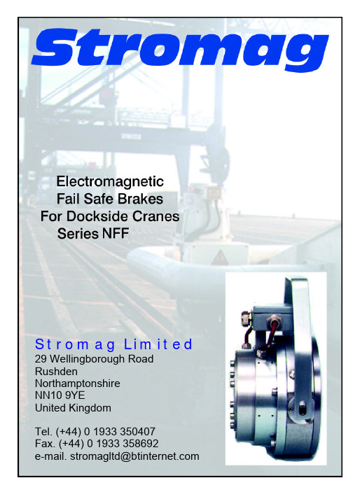
Stromag Limited 29 Wellingborough Road RushdenNorthamptonshireNN10 9YEUnited KingdomTel. (+44) 0 1933 350407Fax. (+44) 0 1933 358692e-mail. stromagltd@Page 2JCB110698Electromagnetic Fail Safe Brakes Series NFA/NFF Stromag Versions:Basic & Dockside CranesStromag Limited29 Wellingborough Road,RushdenNorthamptonshire · NN10 9YE · United KingdomTel. 01933 350407 · Fax. 01933 358692e-mail stromagltd@CB110698Page 3NFA / NFF SERIES BRAKEAdvantages:Comprehensive range 20 -10,000 Nm.Simple assembly to motor, no dismantling of brake required.Concentricity through body for Tacho fixing.No setting required when changing discs, therefore eliminating human error.Compatibility of consumable spares.Simple maintenance, once only adjustment by shim removal.Positive feel hand release mechanism.Proven reliable design.Sealed inspection holes for Airgap / Lining wear.Extremely low inertia.High heat dissipation.Free from axial loads when braking and running.Suitable for vertical mounting (subject to conditions).Many optional extras available.Facilities to design to customer's special requirements.Protection available up to IP66."Asbestos free" linings as standard.Holding and Working brake variations.===============================================================Voltages Available:Standard 24v DC, 97v DC (110v Rectified), and 198v DC (220v Rectified).Other Voltages available.Coils available to suit : AC Supplies with Integral Half and Full Wave rectification.We suggest the following alternative - Customer to take standard voltage 24V / 110VDC, and we can provide Transformer Rectifier unit.Page 4JCB110698Brake Operation :Brakes switched on the DC side. (This will achieve fastest response times).Brakes are FAIL SAFE ie. Spring Applied.Power on to release.When the coil (2), is energised, the magnetic flux attracts the armature plate (3), to the coil body (1), this compresses the springs (8), and releases the brake disc (4).Micro Switch :Optional availability, Inboard Proving Switch, one common contact, one normally open contact and one normally closed contact.This can be interlocked with motor contactor for parking brake duty, ie. brake release before starting motor.Brake Termination :Three standard versions :1) Flyaway leads, usually 1 metre long through PG Cable Gland in Body.2) IP66 Terminal box, for easy connection and removal,3) Versions for AC supply with built-in Full Wave or Half Wave rectification inside the Terminal Box.Please note that when the brake is electrically connected to an AC motor and switched on the AC side, care must be taken so that the load does not drive back into the motor and generate a voltage that may hold the brake off.I.e. in hoist and lift applications. If in doubt please contact the Stromag technical department.Emergency Hand Release Lever :This is set in our works, no setting is required over maximum lining wear.Special Bearing mechanism for easy operation and positive feel.Emergency Jacking Screws available if Hand Release Lever not supplied.Brake Flange :Manufactured to suit our Brake and your Motor.Condensation Heaters :Inboard condensation heaters can be providedTacho / Encoder :Can be provided as optional extras.Special Surface Finishes :Most of the components can be treated with a protective surface coating for arduous environments; ie. Dockside Cranes / Deck mounting etc.CB110698Page 5CALCULATIONSFull Load Torque = FLTLoad Torque = NmTorque = NmKilowatts = Kw9550Speed = rpm Initial Torque, size of brake = FLT x Factor (25% - 200%)Calculating Maximum Stops per Hour using Braking Tables Example:-Motor 15 Kw @ 1500 rpmJ = Total Inertia of Load + Motor = 2.04 Kgm2T L = Load Torque = 20 NmT S = Brake Torque = 100% FLTMotor FLT = Kw x 9550 = 15 x 9550 = 95.5 Nmrpm 1500Brake selection NFA 10 (100 Nm)KJ per switching = J x N2 x TS182000 TS ± TL= 2.04 x 15002 x 100182000 100 + 20= 25.21 x 100 = 21 KJ per switching 120From NFA Braking Tables @ 1500 rpmNFA 10 Brake will stop approx. 40 times per hour.To Calculate Stopping TimeStopping Time = J x rpm9.55 x (TS ±TL)Example:-NFA 10 (100Nm)15Kw @ 1500 rpmMotor and Machine MOI = 2.04Kgm2T L = 20 NmStopping Time = 2.04 x 15009.55 x (100 + 20)Stopping Time = 2.67 seconds + Brake response timePage 6JCB110698NFA Basic Size 2 (20 NM) – Size 1000 (10,000 NM) ApplicationsGeneral engineering brake for a variety of applications.Standard FeaturesCoil Body Class F insulation and platingOuter Body Manufactured in standard Aluminium with PG9 Airgapinspection plug.Armature Plate Standard FinishBrake Flange Standard FinishFriction Lining Low wear rate with low torque fade over widetemperature band. High thermal capacity.End Cover Manufactured in standard AluminiumHub Mild SteelFixings All standard 12.9 Grade Cap ScrewsFlying Leads 1 metre longOptional Extra’s Hand Release LeverTacho/Endcoder ProvisionTerminal BoxMicro-proving SwitchWear detection switchCondensation heatersAdjustable brake torqueSwitching ModulesHalf WaveFull WaveForcing UnitsQuick SwitchingBuilt in Terminal boxOr Free-standingCB110698Page 7NFF Dockside Size 2 (20 NM) – Size 1000 (10,000 NM)ApplicationsDockside/Harbour and Marine Crane brake suitable for Seawater environment.Standard FeaturesCoil Body Class F insulation and platedOuter Body Manufactured in sea water proof aluminium with largeinspection holes and sealed bearing hand release provision. Armature Plate Special protection: Nitrided or PlatedBrake Flange Special protection: Nitrided or PlatedFriction Lining Low wear rate with low torque fade over wide temperature band.High thermal capacity.End Cover Manufactured in sea water proof aluminium with provision forcondensation heater.Hub Stainless SteelFixings All Stainless SteelFlying Leads 1 metre longSeals For high protectionAdjustable brake torque Simple adjustment with C spannerOptional Extra’s Hand Release LeverTacho/Endcover provisionTerminal BoxMicro-proving switchWear detection switchCondensation heatersSwitching ModulesHalf WaveFull WaveForcing UnitsQuick SwitchingBuilt in Terminal BoxOr Free StandingPage 8JCB110698CB110698Page 9Brake Size 24 6.310162540631001602504006301,000Torque (Working)Nm 2040631001602504006301,0001,6002,5004,0006,30010,000Torque (Holding)Nm 3060981402403605809501,4602,3603,7006,0309,27014,700Max Speed Min -15,3004,9004,5004,1003,8003,5003,2003,0002,8002,2001,9001,6001,4001,200Moment of Inertia J - B Side kgm 20.00040.000430.000730.001280.001350.003250.007750.013750.025750.149250.23850.4330.913251.66425Weightkg 5.57.38.610.914.4213444.570120165220325481Nominal Voltage (DC)* *v 2424242424242424110110110110110110Nominal Wattage w 8067103110124149170249270325400482601587Nominal CurrentA 3.34 2.81 4.28 4.57 5.18 6.27.110.4 2.46 2.95 3.64 4.38 5.47 5.34Air Gap Normal 0.60.60.60.60.60.60.60.60.60.60.60.60.60.6Air GapMax 11 1.2 1.2 1.2 1.2 1.3 1.5 1.6 1.6 1.8 1.82 2.1a 150165175190225250270314350440500560650750b 135152162175205225250292325418472530620710c 120140140160180200220240270340390460530600d max H72530* 40* 404550606080110120130140160e 55556068.27678.59096100200215240270300h 3034322731313333343333333333l 73.589.692.895.3104121141145168182.6191226225265m 10.57.810.61514.51714.25212024.421.426.33030n 2.5 2.5 2.5 3.5 3.5 3.5445 5.55566p 242830303555455575125130150185210s 7.57.57.5109101012101010101010t123140150146168172184230# 230270280320340380 6screwsk M5M6M6M6M8M8M8M10M10M12M16M16M16M20f478080658090105120158220255280320330* * Other Voltages Available * With t2 keyways Din 6885 (2)# 255 when adjusting nut requiredStromag Electromagnetic Spring Applied Brake Series NFA (Basic Design)Page 10JCB110698Brake Size24 6.310162540631001602504006301,000M 115.5128.5128125151165179196238260290327364420K 179.5203198210245276300343376J 20.92829293239404554Refer to StromagL 95110110123140150170200220X 1933.7533.753848628386113125.5133.5168172182Q110110110110110150150250500Dimensions not given are available on requestConsult chart before orderingSeries Size 1st Digit BasicDesign Brake Flange Hand Release Lever M/C for Tacho AdjustableTorque2nd Digit Terminal Box PG Gland Micro Switch RectifierHeaterB lA l C lB l lD l l C lEl l D l l NFAF ll l E l l lG l F l l H l lGl l K l H l l lL l l K l l MlllL l l l M l l l Nlll lExample :- NFA 63 EC-24v DCIs a Brake Size 63 (630Nm) with Hand Release, Zag 3 Terminal Box with PG11 Gland and 24v DC CoilStromag Electromagnetic Spring Applied Brake Series NFA (Basic Design)Jack Off Screws are suppliedloose for emergency release Protection available up to IP66Special variations available on requesta) Terminal Box, Large ZAG6b) Proximity Sensorc) Wear Detection SwitchBrake Size24 6.310162540631001602504006301,000M 115.5128.5128125151165179196238260290327364420K 179.5203198210245276300343376J 20.92829293239404554Refer to StromagL 95110110123140150170200220X 1933.7533.753848628386113125.5133.5168172182Q110110110110110150150250500Dimensions not given are available on requestConsult chart before orderingSeries Size 1st Digit BasicDesign Brake Flange Hand Release Lever M/C for Tacho AdjustableTorque2nd Digit Terminal Box PG Gland Micro Switch RectifierHeaterB lA l C lB l lD l l C lEl l D l l NFFF ll l E l l lG l F l l H l lGl l K l H l l lL l l K l l MlllL l l l M l l l Nlll lExample :- NFF 63 EC-24v DCIs a Brake Size 63 (630Nm) with Hand Release, Zag 3 Terminal Box with PG11 Gland and 24v DC CoilStromag Electromagnetic Spring Applied Brake Series NFF (Dockside)Optional AccessoriesJack Off Screws are suppliedloose for emergency releaseProtection available up to IP66Special variations available on requesta) Terminal Box, Large ZAG6b) Proximity Sensorc) Wear Detection SwitchTabulated Permissible Heat / Energy CapacitySeries NFA / NFFEnergy KJ / Switching @ 1000 RPMBrake Size24 6.310162540631001602504406301,000117.714.6274562921542092985407028419961,304517.714.6274562921542092984485827148621,1431017.714.6274562921542092963644806007389902017.714.627425464891101481942733775137393013.69.718.92836435973991291822513424934010.27.314.22127324455749713618825636960 6.8 4.99.41418213037506491125171246100 4.1 2.9 5.78.511131822303955751021471,0000.410.290.570.851.11.31.82.23.03.95.57.510.214.7Energy KJ / Switching @ 1500 RPMBrake Size24 6.310162540631001602504006301,000117.714.627456292154209298373476570672880517.714.6274562921542092903234185086088031017.714.6274562921542022432773624485447243013.69.718.92836435973991291622513424934010.27.314.22127324455749713618825636960 6.8 4.99.41418213037496491125171246100 4.1 2.9 5.78.511131822293955751031471,0000.410.290.570.851.11.31.82.22.93.95.57.510.314.7Energy KJ / Switching @ 3000 RPMBrake Size24 6.310162*********17.714.627456292154209298517.714.6274562921542092901017.714.6274562921542022433013.69.718.92836435973994010.27.314.221273244557460 6.8 4.99.4141821303749100 4.1 2.9 5.78.511131822291,0000.410.290.570.851.11.31.82.22.9Note:- The number of switchings must be spread evenly over an hourS w i t c h i n gS w i t c h i n gS w i t c h i n g165946731219291081Supplied Encapsulated22627112215The user of the brake must observe the respective regulations for prevention of accidents (Law applicable to working means).Spare part orders should indicate the following data:-1) Stromag Ref. No.2) Series and Size 3) Item and NumberConstruction & FunctioningThis brake is a fail safe spring-applied double faced brake, with electromagnetic release. When the coil is de-energised the pressure springs (19) push the armature disc (4) axially against the friction lining assy. (5). This is clamped between the armature disc (4) and the brake flange (7) thereby preventing rotation.The braking effect is transmitted through the friction lining carrier (5) to the shaft by way of a splined driving hub (6). When the coil is energised, the armature disc (4) is attracted towards the coil body (1) by electromagnetic force overcoming the pressure springs (19). Thereby the friction lining assy. (5) is released.AssemblyThe hub should be fitted to the shaft and retained by a good fitting key and axially located. The assembly to the motor is simple, no dismantling of the brake is required.Offer brake onto the motor spigot ensuring friction lining and assy. (5) is centralised.Tighten fixing screws (23) to correct bolt tightening torque (as specified on the drawing). Terminate brake as per wiring diagram in terminal box.Seal face between brake and motor with Hylomar gasket sealer to conform to IP 65.Emergency ReleaseNFA/NFF Version : By pulling the hand lever towards the back of the brake theWith Hand Release armature (4) is moved axially until it is lying against the coil body Lever (1), thus the friction assy may rotate freely.NFA /NFF Version :By inserting the Jack Off screws through the coil body into the Without Hand armature and tightening, the armature is moved axially against Release Lever the coil body, thus the friction assy may rotate freely.Attention: These measures shall be applied during maintenance, assembly or emergency conditions only.Operating Instructions for ElectromagneticSpring applied NFA / NFF Brake (Construction & Assembly)StromagIn the course of the working life of the brake, an increase of the airgap between coil body (1) and armature disc (4) will occur.For correct operation of the brake, ensure that the airgap maximum (rate specified in the drawing) is not exceeded, if the airgap is greater than this, re-adjust to normal dimension (also specified in drawing).To check the airgap dimension remove the inspection cover (22) and place a non-magnetic feeler gauge between the coil body (1) and armature (4).THERMAL CAPACITY; The brake is capable of absorbing a certain amount of energy during one emergency stop (As stated in the charts in our catalogue).Ensure all excessive dust and contamination is removed (this may impair operation of the micro switch).Strip brakes after commissioning and clean.Term of inspection six monthly, thereafter adjusted from evidence found.IF THERMAL CAPACITY IS EXCEEDED INSPECTION OF FRICTION LININGS,ARMATURE BACKPLATE AND COIL IS REQUIRED.Re-adjustment of the airgapIf the maximum airgap is reached, a re-adjustment to the normal airgap dimension must be made, this is done as follows:-Remove screws (23,25) dismantle coil body assembly and non magnetic outer body (2)from brake flange (7) taking care not to lose pressure springs (19) or damage armature plate(4).Remove shim (3) and re-assemble. The armature may be retained in position by using the emergency release screws. Ensure these are removed after re-assembly.Note: If the shim has previously been removed, a new lining assembly (5) together with shim (3) has to be fitted.Attention: On assembling the brake or replacing the friction lining assembly, care should be taken that the linings do not come in contact with grease etc. Greasy substances if any, can be removed by suitable degreasing agents. Never use petrol or paraffin.NOTE; USE ONLY GENUINE Stromag FRICTION LINING SPARES WHICH ARE NON ASBESTOS.StromagOperating Instructions for ElectromagneticSpring applied NFA / NFF Brake (Construction & Assembly)StromagStromagHousing colour for Halfwave version: BlackHousing colour for Fullwave version: GreyBy removing wire link and connecting instead, a contact (or No. of contacts in series) the D.C. output to coil is switched on the D.C. side of the Rectifier giving a 4 to 8 times faster application of the Brake (t2).Electrical connection via a 6 pole Terminal Block.Stripping length for cable: 6mm/0.25”.Cable size: 0.5mm - 2.5mm.EGV 500-5 Halfwave Rectifier Unit for Max. 500vAC Input, 1.8 amps Max. output.BG 270-5 - Fullwave Rectifier Unit for Max. 270vAC Input, 1.8 amps Max. output.The input and output for both types of Rectifier Unit are protected against overvoltage by Varistors.The Halfwave version EGV 500-5 also incorporates a Varistor to protect the D.C. switch contacts.Customer: __________________________________________________ Installation Site if known: ______________________________________ Enquiry No: _____________Order No: __________________Brake Size and Description: _________________________ See Catalogue IP Protection required: IP __________ Input Voltage: ___________ AC / DCHeater (Anti-condensation ) Voltage 110v / 240v ACHand Release Lever: Y / NVertical / Horizontal Shaft Application: H / VBore Requirements: _____________________________ Keyway Requirements: ___________________________Backplate Spigot dimensions: _______________________ Male / Female Terminal Box: Y / N Size: Large (Zag 6) Small (Zag 3) End Cap Fitted: Y / NTacho Fitted: Y / N Fixing Dimensions: __________________________ Additional machining / Special Requirements:Previous Order Ref. _____________________________________________Special adapter/adapters mounting plates or seals etc. Please specify. ____________________________________________________________ ____________________________________________________________ ____________________________________________________________StromagORDER CHECK LISTNFF/NFA/NFH SeriesWe have supplied since 1988 in excess of 3000 NFA/NFF Brakes for high protection,Dockside Crane applications.The following Motor Manufacturers have used our Brakes:-Bull Electric Siemens Thrige Scott Marelli Mawdsley Sicme Motori David McClure IEG AnsaldoBrook CromptonVME A.B.B.Hyosung Teco AEG BauerMagneticThey have been used on the following Cranes: -Morris’s Stothert & Pitt Butterley MWG MagriniB.M. Titan KHIC Rolls RoyceSchnieder ImsaStreetInstallations Include: -Felixstowe Hong Kong Miami Southampton Pusan Port S. KoreaPenang Calcutta Cork Singapore Bombay Dundalk VancouverMadras Limerick Hull Tanjin Tilbury Immingham ShanghaiCharlstonFraser River StromagREFERENCE LISTStromag AGD-59411 Unna, Postfach 2123 . D-59425 Unna, Hansastr. 120 . Tel. (02303) 102-0 . Fax. (02303) 102-201。
(整理)图解盘式制动器.

图解盘式制动器1.盘式制动器概述盘式制动器摩擦副中的旋转元件是以端面工作的金属圆盘,被称为制动盘。
其固定元件则有着多种结构型式,大体上可分为两类。
一类是工作面积不大的摩擦块与其金属背板组成的制动块,每个制动器中有2~4个。
这些制动块及其促动装置都装在横跨制动盘两侧的夹钳形支架中,总称为制动钳。
这种由制动盘和制动钳组成的制动器称为钳盘式制动器。
另一类固定元件的金属背板和摩擦片也呈圆盘形,制动盘的全部工作面可同时与摩擦片接触,这种制动器称为全盘式制动器。
钳盘式制动器过去只用作中央制动器,但目前则愈来愈多地被各级轿车和货车用作车轮制动器。
全盘式制动器只有少数汽车(主要是重型汽车)采用为车轮制动器。
这里只介绍钳盘式制动器。
钳盘式制动器又可分为定钳盘式和浮钳盘式两类。
盘式制动器结构图如下图所示2.定钳盘式制动器跨置在制动盘1上的制动钳体5固定安装在车桥6上,它不能旋转也不能沿制动盘轴线方向移动,其内的两个活塞2分别位于制动盘1的两侧。
制动时,制动油液由制动总泵(制动主缸)经进油口4进入钳体中两个相通的液压腔中,将两侧的制动块3压向与车轮固定连接的制动盘1,从而产生制动。
这种制动器存在着以下缺点:油缸较多,使制动钳结构复杂;油缸分置于制动盘两侧,必须用跨越制动盘的钳内油道或外部油管来连通,这使得制动钳的尺寸过大,难以安装在现代化轿车的轮辋内;热负荷大时,油缸和跨越制动盘的油管或油道中的制动液容易受热汽化;若要兼用于驻车制动,则必须加装一个机械促动的驻车制动钳。
定钳盘式制动器示意图1.制动盘2.活塞3.摩擦块4.进油口5.制动钳体6.车桥部3.浮钳盘式制动器制动钳体2通过导向销6与车桥7相连,可以相对于制动盘1轴向移动。
制动钳体只在制动盘的内侧设置油缸,而外侧的制动块则附装在钳体上。
制动时,液压油通过进油口5进入制动油缸,推动活塞4及其上的摩擦块向右移动,并压到制动盘上,并使得油缸连同制动钳体整体沿销钉向左移动,直到制动盘右侧的摩擦块也压到制动盘上夹住制动盘并使其制动。
图解盘式制动器.

图解盘式制动器1.盘式制动器概述盘式制动器摩擦副中的旋转元件是以端面工作的金属圆盘,被称为制动盘。
其固定元件则有着多种结构型式,大体上可分为两类。
一类是工作面积不大的摩擦块与其金属背板组成的制动块,每个制动器中有2~4个。
这些制动块及其促动装置都装在横跨制动盘两侧的夹钳形支架中,总称为制动钳。
这种由制动盘和制动钳组成的制动器称为钳盘式制动器。
另一类固定元件的金属背板和摩擦片也呈圆盘形,制动盘的全部工作面可同时与摩擦片接触,这种制动器称为全盘式制动器。
钳盘式制动器过去只用作中央制动器,但目前则愈来愈多地被各级轿车和货车用作车轮制动器。
全盘式制动器只有少数汽车(主要是重型汽车)采用为车轮制动器。
这里只介绍钳盘式制动器。
钳盘式制动器又可分为定钳盘式和浮钳盘式两类。
盘式制动器结构图如下图所示2.定钳盘式制动器跨置在制动盘1上的制动钳体5固定安装在车桥6上,它不能旋转也不能沿制动盘轴线方向移动,其内的两个活塞2分别位于制动盘1的两侧。
制动时,制动油液由制动总泵(制动主缸)经进油口4进入钳体中两个相通的液压腔中,将两侧的制动块3压向与车轮固定连接的制动盘1,从而产生制动。
这种制动器存在着以下缺点:油缸较多,使制动钳结构复杂;油缸分置于制动盘两侧,必须用跨越制动盘的钳内油道或外部油管来连通,这使得制动钳的尺寸过大,难以安装在现代化轿车的轮辋内;热负荷大时,油缸和跨越制动盘的油管或油道中的制动液容易受热汽化;若要兼用于驻车制动,则必须加装一个机械促动的驻车制动钳。
定钳盘式制动器示意图1.制动盘2.活塞3.摩擦块4.进油口5.制动钳体6.车桥部3.浮钳盘式制动器制动钳体2通过导向销6与车桥7相连,可以相对于制动盘1轴向移动。
制动钳体只在制动盘的内侧设置油缸,而外侧的制动块则附装在钳体上。
制动时,液压油通过进油口5进入制动油缸,推动活塞4及其上的摩擦块向右移动,并压到制动盘上,并使得油缸连同制动钳体整体沿销钉向左移动,直到制动盘右侧的摩擦块也压到制动盘上夹住制动盘并使其制动。
盘式制动器

2.制动盘厚度
制动盘厚度对制动盘质量和工作时的温升有影响。为使质量小些,制动盘厚度不宜取得很大;为了降低温度, 制动盘厚度又不宜取得过小。制动盘可以做成实心的,或者为了散热通风的需要在制动盘中间铸出通风孔道。一 般实心制动盘厚度可取为10—20mm,通风式制动盘厚度取为20~50mm,采用较多的是20—30mm。在高速运动下 紧急制动,制动盘会形成热变形,产生颤抖。为提高制动盘摩擦面的散热性能,大多把制动盘做成中间空洞的通风 式制动盘,这样可使制动盘温度降低20 %~30%。
谢谢观看
盘式制动器沿制动盘向施力,制动轴不受弯矩,径向尺寸小。
用途
盘式制动器已广泛应用于轿车,现在大部分轿车用于全部车轮,少数轿车只用作前轮制动器,与后轮的鼓式 制动器配合,以使汽车有较高的制动时的方向稳定性。在商用车中,目前盘式制动器在新车型及高端车型中逐渐 被采用。
主要组成
制动盘
摩擦衬块
1.制动盘直径
制动力疲软,不总的原因有:(a)制动器漏油;(b)制动油路中有空气;(c)轮毂油封破损,钳盘上有油污; (d)制动严重磨损,摩擦面烧损;(e)气路气压调整过低。
解决方法: 1、改变制动衬块材料 可换用稍软的制动衬块材料,使摩擦系数相对得到提高,制动力变大。 2、清除制动衬块排屑槽中的异物 如果制动衬块的排屑槽被异物覆盖,制动时将失却排出尘土、刮去水分的作用,使制动力降低。 制动后跑偏 跑偏的直接原因是两侧车轮的制动力矩不等所致,常见的故障原因:(a)制动钳盘油污严重,摩擦系统数严 重下降,造成制动力矩不平衡,此时应清除制动钳盘上的油污;(b)分泵活塞卡滞不能工作。静车踩制动,观察 分泵工作情况,视情拆检。
国外几家气压盘式制动器的比较

3、制造成本:威伯科、克诺尔低于翰德、美驰 克诺尔、威伯科的零件数量少于翰德、美驰。
结论
综合考虑工作可靠性、制造工艺性及制造成 本,优选方案为:
分体式钳体+克诺尔间隙自调机构
棘轮
克诺尔自调机构工作原理
在每次制动的同时,摇臂的拨叉插在主调整装置的单向离 合器拨叉内转动,当转动量超过摇臂拨叉的预设间隙时,设 计制动间隙消除,这时滚针离合器处于锁死状态,带动单向 离合器法兰转动,过载离合器壳体由于过载弹簧的压力,通 过钢球与单向法兰结合在一起,同步转动,并带动该侧的推 杆旋转,从动调整装置由链条链轮的传动,与主调整装置同 步转动,带动另一侧的推杆旋转,消除过量间隙。过量间隙 消除后,推杆与推杆连接桥间的压力迅速增大,摩擦力也迅 速增大,旋转停止。如果这时制动并没有停止,钳体会发生 一定的弹性变形,摇臂会继续转动一定的角度,这时单向法 兰带动钢球在过载离合器壳体端面的球窝中移位,消除作用 在滚针离合器上过载的扭矩。解除制动时,摇臂回转,带动 单向离合器拨叉回转,滚针离合器处于松开状态,推杆不再 转动。
制动器结构——美驰制动器
制动器结构——美驰自调机构
制动器结构——美驰自调机构
美驰制动器自调机构工作原理
在每次制动的同时,固定在摇臂上的球头销在拨叉内转 动,当转动量超过拨叉的预设间隙时,设计制动间隙消除, 拨叉的轴与压盘滚花连接,压盘与拨叉一起转动,齿片与 套筒键齿连接,成为一体,回位弹簧的压力将齿片压在压 盘上,通过摩擦将转动传递给套筒,再通过摩擦簧传递给 齿轮3,齿轮3将转动传递给齿轮1/2,齿轮1/2分别与推杆 1/2螺纹连接,两推杆不转动,从而将齿轮1/2的旋动转化成 两推杆 的轴向运动,消除过量间隙。过量间隙消除后, 齿 轮1/2与两推杆间的压力迅速增大,摩擦力也迅速增大,旋 动停止。如果这时制动并没有停止,钳体会发生一定的弹 性变形,摇臂会继续转动一定的角度,通过齿片与压盘的 滑动,消除作用在摩擦簧上过载的摩擦力。解除制动时, 摇臂回转,摇臂上的球头销带动拨叉回转,摩擦簧分离, 齿轮1/2不再转动。
瀚德盘式制动器安全操作及保养规程

瀚德盘式制动器安全操作及保养规程瀚德盘式制动器是一种常见的机械制动设备,适用于各种机械设备的制动和停止。
在日常使用中,正确的操作和保养可以延长其使用寿命、保障设备的安全性能,因此,本文将介绍瀚德盘式制动器的安全操作及保养规程。
安全操作规程1. 安装前检查在安装瀚德盘式制动器前,应检查其零部件的数量、质量和配件是否齐全,并对其进行外观和尺寸等方面的检查。
在检查时,应检查制动器内部是否有异物,是否良好的润滑和清洁。
若有异常,应及时联系供应商进行排查。
2. 安装和调试在安装完瀚德盘式制动器后,应按照其安装说明书进行正确调整和安装。
在安装时,应注意选择合适的安装位置和安装方式,并确保制动器和被控制机械设备之间的联接牢固、正确。
在调试时,应注意切勿超出制动器额定的工作压力范围,一旦发现问题应及时调整和通知维修人员。
3. 启动和操作在启动和操作瀚德盘式制动器前,应按照相关规定和工艺流程,严格控制气源和电源的开启时间和顺序,避免短路或过载等问题。
在操作时,应注意控制制动力度和时间,并灵活运用制动器的功能,确保工作安全。
4. 关闭和停机在停机前,应一步步按照工艺流程进行操作,控制制动力度和时间,并在保证安全的前提下,尽可能地减小对被控制机械设备的影响。
保养规程1. 日常维护在日常使用中,应按照瀚德盘式制动器的维护手册,进行日常维护工作。
清洗及润滑轴承和内部部件,注意清理污垢及异物,保证空气管路畅通,定期检查制动力度,及时加注油脂并替换易损件。
2. 周期检查制动器作为关键的安全设备,需要定期进行检查和维护,确保其正常工作。
定期检查制动电磁铁的内部状况和制动片的磨损情况,并根据使用情况,进行相应的维护和更换。
同时,还应定期检查和校准制动力度和制动时间等参数。
3. 特殊情况的保养在恶劣环境或特殊场合下,瀚德盘式制动器需要更加注意和细心的保养。
例如,在潮湿的环境中使用,需要及时清理水和异物,以避免电磁铁受潮而导致损坏或停机故障。
- 1、下载文档前请自行甄别文档内容的完整性,平台不提供额外的编辑、内容补充、找答案等附加服务。
- 2、"仅部分预览"的文档,不可在线预览部分如存在完整性等问题,可反馈申请退款(可完整预览的文档不适用该条件!)。
- 3、如文档侵犯您的权益,请联系客服反馈,我们会尽快为您处理(人工客服工作时间:9:00-18:30)。
STROMAG STROMAG制动器、STROMAG盘式制动器、STROMAG限位开关、STROMAG 电磁离合器、STROMAG电磁离合器、STROMAG抱闸摩擦片、STROMAG角度编码器、STROMAG驱动模块。
德国STROMAG集团是机械动力传动技术领域中各种难题的解决者。
我们通过与客户设计部门的密切合作,在传动链方面努力开发有创新思维的解决方法,并最终应用在相应的产品生产中。
德国STROMAG是一个能够在世界范围提供如此广泛和完善服务的制造商。
我们通过对生产中的工艺流程和实际操作方面的深入研究和严格控制,确保产品在各相关领域中处于技术地位。
更通过DIN ISO9001 质量体系的认证,使我们在给各个领域提供技术支持方面发挥着领导者的巨大作用。
STROMAG的工程师拥有优异的技术知识。
他们将战略焦点明确地集中在生产和应用方面的核心技术上,使我们能在极短的时间内为客户解决机械传动领域的难题,并提供完美的解决方案。
产品包括:德国STROMAG制动器、STROMAG盘式制动器、STROMAG限位开关、STROMAG电磁离合器、STROMAG电磁离合器、STROMAG抱闸摩擦片、STROMAG角度编码器、STROMAG驱动模块。
上海智川工贸有限公司专业销售德国STROMAG制动器、STROMAG盘式制动器、STROMAG限位开关、STROMAG电磁离合器、STROMAG电磁离合器、STROMAG抱闸摩擦片、STROMAG角度编码器、STROMAG驱动模块。