海康录像机_手机监控教程
海康威视网络硬盘录像机操作说明讲解学习

海康威视网络硬盘录像机操作说明讲解学习首先,打开硬盘录像机的电源开关,接通电源后,触摸屏上将会出现欢迎界面。
在欢迎界面上,可以设置系统的时间、网络配置等信息。
1.录像功能在主界面上,点击左侧的“录像”按钮,进入录像设置界面。
在此界面上,可以设置录像通道、录像计划、录像模式等参数。
点击“通道”选项,可以选择需要录像的通道,然后选择录像计划,可以设置录像的起始时间和结束时间。
在录像模式中,可以选择手动录像、定时录像、报警录像等模式。
设置完成后,点击“确定”按钮即可开始录像。
2.播放功能在主界面上,点击左侧的“回放”按钮,进入录像回放界面。
在回放界面上,可以选择日期和时间,然后点击“查询”按钮,系统将显示该时间段内的录像文件。
点击文件列表中的文件,然后点击“播放”按钮,即可开始回放视频。
3.报警功能在主界面上,点击左侧的“报警”按钮,进入报警设置界面。
在此界面上,可以设置报警通道、报警联动、报警输出等参数。
点击“通道”选项,可以选择需要设置报警的通道,然后选择报警联动方式,可以选择触发报警时的操作,如声音提示、发送邮件等。
在报警输出中,可以选择报警时是否输出警示信息。
4.远程访问功能硬盘录像机可以通过网络远程访问,实现实时监控和录像回放。
首先,在主界面上点击左侧的“设置”按钮,进入设置界面。
然后点击“网络”选项,进行网络配置。
在网络配置中,可以设置网络连接方式、IP地址、DNS服务器等参数。
设置完成后,点击“确定”按钮。
接下来,在电脑或手机上安装海康威视的远程监控客户端,然后输入硬盘录像机的IP地址和端口号,即可进行远程访问。
5.存储管理功能硬盘录像机可以管理录像文件的存储空间。
在主界面上,点击左侧的“存储”按钮,进入存储管理界面。
在此界面上,可以查看当前硬盘空间的使用情况,以及设置存储策略。
点击“存储策略”选项,可以选择录像覆盖方式和录像保存时长。
设置完成后,点击“确定”按钮。
以上就是海康威视网络硬盘录像机的一些基本操作步骤和常见功能。
海康录像机-手机监控教程

- 用户手册V1.1 手机监控软件-直连模式 . 用户手册1 非常感谢您购买我公司的产品,如果您有什么疑问或需要请随时联系我们。
本手册适用于手机监控软件-直连模式。
本手册可能包含技术上不准确的地方、或与产品功能及操作不相符的地方、或印刷错误。
我司将根据产品功能的增强而更新本手册的内容,并将定期改进或更新本手册中描述的产品或程序。
更新的内容将会在本手册的新版本中加入,恕不另行通知。
手机监控软件-直连模式 . 用户手册 2 目录 1 简介 ................................................................................ ........................................................... 3 1.1 简介 ................................................................................ ............................................... 3 1.2 性能概述 ................................................................................ ....................................... 3 1.3 运行环境 ................................................................................ ....................................... 3 1.4 约定 ................................................................................ ............................................... 4 2 安装和准备 ................................................................................ ............................................... 5 2.1 设备设置 ....................................................................................................................... 5 2.2 软件的安装 ................................................................................ ................................... 5 3 软件运行 ................................................................................ ................................................... 7 3.1 设备管理 ................................................................................ ....................................... 7 3.2 预览 ................................................................................ ............................................... 8 3.3 云台控制 ................................................................................ ..................................... 10 手机监控软件-直连模式 . 用户手册 3 1 简介 1.1 简介手机监控软件-直连模式运行于手机平台,通过无线网络,实现对硬盘录像机、视频服务器、网络摄像机和网络球机的实时图像预览和云台控制。
Hikvision 手机视频录像机快速上手指南及安装指南说明书

Mobile Video RecorderQuick Start GuideLegal Information©2022 Hangzhou Hikvision Digital Technology Co., Ltd. All rights reserved.About this ManualThe Manual includes instructions for using and managing the Product. Pictures, charts, images and all other information hereinafter are for description and explanation only. The information contained in the Manual is subject to change, without notice, due to firmware updates or other reasons. Please find the latest version of this Manual at the Hikvision website (https:///).Please use this Manual with the guidance and assistance of professionals trained in supporting the Product.Trademarksand other Hikvision’s trademarks and logos are the properties of Hikvision in various jurisdicti ons. Other trademarks and logos mentioned are the properties of their respective owners.DisclaimerTO THE MAXIMUM EXTENT PERMITTED BY APPLICABLE LAW, THIS MANUAL AND THE PRODUCT DESCRIBED, WITH ITS HARDWARE, SOFTWARE AND FIRMWARE, ARE PROVIDED “AS IS” AND “WITH ALL FAULTS AND ERRORS”. HIKVISION MAKES NO WARRANTIES, EXPRESS OR IMPLIED, INCLUDING WITHOUT LIMITATION, MERCHANTABILITY, SATISFACTORY QUALITY, OR FITNESS FOR A PARTICULAR PURPOSE. THE USE OF THE PRODUCT BY YOU IS AT YOUR OWN RISK. IN NO EVENT WILL HIKVISION BE LIABLE TO YOU FOR ANY SPECIAL, CONSEQUENTIAL, INCIDENTAL, OR INDIRECT DAMAGES, INCLUDING, AMONG OTHERS, DAMAGES FOR LOSS OF BUSINESS PROFITS, BUSINESS INTERRUPTION, OR LOSS OF DATA, CORRUPTION OF SYSTEMS, OR LOSS OF DOCUMENTATION, WHETHER BASED ON BREACH OF CONTRACT, TORT (INCLUDING NEGLIGENCE), PRODUCT LIABILITY, OR OTHERWISE, IN CONNECTION WITH THE USE OF THE PRODUCT, EVEN IF HIKVISION HAS BEEN ADVISED OF THE POSSIBILITY OF SUCH DAMAGES OR LOSS.YOU ACKNOWLEDGE THAT THE NATURE OF THE INTERNET PROVIDES FOR INHERENT SECURITY RISKS, AND HIKVISION SHALL NOT TAKE ANY RESPONSIBILITIES FOR ABNORMAL OPERATION, PRIVACY LEAKAGE OR OTHER DAMAGES RESULTING FROM CYBER-ATTACK, HACKER ATTACK, VIRUS INFECTION, OR OTHER INTERNET SECURITY RISKS; HOWEVER, HIKVISION WILL PROVIDE TIMELY TECHNICAL SUPPORT IF REQUIRED.YOU AGREE TO USE THIS PRODUCT IN COMPLIANCE WITH ALL APPLICABLE LAWS, AND YOU ARE SOLELY RESPONSIBLE FOR ENSURING THAT YOUR USE CONFORMS TO THE APPLICABLE LAW. ESPECIALLY, YOU ARE RESPONSIBLE, FOR USING THIS PRODUCT IN A MANNER THAT DOES NOT INFRINGE ON THE RIGHTS OF THIRD PARTIES, INCLUDING WITHOUT LIMITATION, RIGHTS OF PUBLICITY, INTELLECTUAL PROPERTY RIGHTS, OR DATA PROTECTION AND OTHER PRIVACY RIGHTS. YOU SHALL NOT USE THIS PRODUCT FOR ANY PROHIBITED END-USES, INCLUDING THE DEVELOPMENT OR PRODUCTION OF WEAPONS OF MASS DESTRUCTION, THE DEVELOPMENT OR PRODUCTION OF CHEMICAL OR BIOLOGICAL WEAPONS, ANY ACTIVITIES IN THE CONTEXT RELATED TO ANY NUCLEAR EXPLOSIVE OR UNSAFE NUCLEAR FUEL-CYCLE, OR IN SUPPORT OF HUMAN RIGHTS ABUSES.IN THE EVENT OF ANY CONFLICTS BETWEEN THIS MANUAL AND THE APPLICABLE LAW, THE LATTER PREVAILS.Regulatory InformationFCC InformationPlease take attention that changes or modification not expressly approved by the party responsible for compliance could void the user’s authority to operate the equipment.FCC ComplianceThis equipment has been tested and found to comply with the limits for a Class A digital device, pursuant to part 15 of the FCC Rules. These limits are designed to provide reasonable protection against harmful interference when the equipment is operated in a commercial environment. This equipment generates, uses, and can radiate radio frequency energy and, if not installed and used in accordance with the instruction manual, may cause harmful interference to radio communications. Operation of this equipment in a residential area is likely to cause harmful interference in which case the user will be required to correct the interference at his own expense.FCC ConditionsThis device complies with part 15 of the FCC Rules. Operation is subject to the following two conditions:1.This device may not cause harmful interference.2.This device must accept any interference received, including interference that may causeundesired operation.EU Conformity StatementThis product and - if applicable - the supplied accessories too are marked with "CE" andcomply therefore with the applicable harmonized European standards listed under the EMC Directive 2014/30/EU, the LVD Directive 2014/35/EU, the RoHS Directive 2011/65/EU, RE Directive 2014/53/EU.2012/19/EU (WEEE directive): Products marked with this symbol cannot be disposed of as unsorted municipal waste in the European Union. For proper recycling, return this product to your local supplier upon the purchase of equivalent new equipment, or dispose of it at designated collection points. For more information see: 2006/66/EC (battery directive): This product contains a battery that cannot be disposedof as unsorted municipal waste in the European Union. See the product documentation for specific battery information. The battery is marked with this symbol, which may include lettering to indicate cadmium (Cd), lead (Pb), or mercury (Hg). For proper recycling, return the battery to your supplier or to a designated collection point. For more information see: Industry Canada ICES-003 ComplianceThis device meets the CAN ICES-3 (A)/NMB-3(A) standards requirements.Symbol ConventionsTABLE OF CONTENTSChapter 1 Panel Introduction (1)Front Panel (1)Rear Panel (2)Chapter 2 Installation and Connections (4)Environment (4)Install HDD (4)Install SIM Card (8)Install SD Card (9)Install Antenna (10)Chapter 3 Device Wiring (12)Power Cord Wiring (12)3.1.1 Shutdown Delay (12)3.1.2 Scheduled Shutdown (13)Alarm Input/Output Connection (14)3.2.1 Alarm Input Connection (14)3.2.2 Alarm Output Connection (14)Sensor-in Wiring (15)Power-on (15)Chapter 1 Panel Introduction Front PanelFront PanelNo. Name Description1 Dummy HDD Two HDDs can be installed.2 Network interface 10M/100M/1000M RJ45 Ethernet interface.3 USB 3.0 USB 3.0 interface.4 PWR indicator●Solid green: Device is powered on.●Solid red: Device is standby.RDY indicator ●Solid green: Device starts up normally. REC indicator●Recording indicator.●Solid green: Device is recording normally. GNSS indicator●Unlit: Positioning module is abnormal.●Solid green: Device is positioning.●Flashing green: Positioning succeeded. ANT indicator●Unlit: Dialing module is abnormal.●Solid green: Device is dialing.●Flashing green: Dialing up succeeded. ALM indicator Red: Alarm occurs.Rear PanelRear Panel5IR receiver IR receiver for remote control. 6Dummy HDD lock Lock/unlock the dummy HDD. 7 SD card slot Slot for SD card.No. NameDescription 1RS-485 interface RS-485 interface for connecting devices like speed dome. 2RS-232 interface RS232-1 is for debugging. 3RS-232 interface RS232-2 is for connecting external devices. 4EXT.DEV RS-485 communication interface, two-way audio interface, and CVBS video output 5VGA VGA video output interface 6 USB interface USB interface of 5-pin aviation plug.Chapter 2 Installation and ConnectionsEnvironmentTo ensure the device can ventilate well, find a position with enough space. Recommended installation space is shown in Figure 2-1.Recommended Installation SpaceInstall HDDBefore You Start:Prepare the tools and components for installation:●Factory recommended 2.5-inch HDD.●Antistatic gloves.●Key to dummy HDD (delivered with device).●Cross screwdriver.●Screws (delivered with device).ToolsPurpose:Perform the following steps to install the HDD on the device. Figures in following steps are only for reference.Wear antistatic gloves.Insert the key and turn counterclockwise to unlock dummy HDD.Unfasten the two screws of dummy HDD and pull dummy HDD out of device.Dummy HDDUnfasten ScrewsPull Dummy HDD outUse cross screwdriver to loosen the two screws and remove them, and then take the dummy HDD apart.Place the first HDD into the dummy HDD, with the PCB facing down.Place HDDPush the HDD along the direction shown in Figure 2-6 to connect HDD with socket of dummyHDD.Push HDDUse four sunk screws to fix HDD with dummy HDD.Fix HDDRepeat step 4 to 6 to install the secondary HDD in the other socket of dummy HDD.Install the Other HDDReassemble the dummy HDD.Reassemble Dummy HDDPlug the dummy HDD back to the device and then tighten the screws clockwise.Turn the key clockwise to lock dummy HDD.Install SIM CardPurpose:Pluggable 4G/5G wireless communication module is designed for the device and you should install the SIM card to realize the wireless communication function.Before You StartPrepare the tools and components for installation:●SIM card●WrenchPhillips ScrewdriverWear antistatic gloves.Use wrench to unfasten and remove the two screws fixing the 4G/5G and Wi-Fi module.Unfasten ScrewsPull out the 4G/5G and Wi-Fi module. Press the yellow button on the 4G/5G slot and then pull the SIM card tray out.Place the SIM card on SIM card tray with the metal side facing upwards.Insert the SIM card tray back to SIM card slot.Install the 4G/5G module back to the device and tighten the set screw.Install SD CardBefore You StartPrepare the tools and components for installation:● Key to dummy HDD (delivered with device)● SD cardToolsWear antistatic gloves.Insert the key and turn counterclockwise to unlock dummy HDD.Unfasten the two screws of dummy HDD and pull dummy HDD out of device.Unfasten ScrewsDummy HDDUnfasten ScrewsOpen the cover of SD card slot.Insert SD card into SD card slot with gold contacts facing down till you hear a click.Plug the dummy HDD back to the device, close the cover of SD card slot, and then tighten the screws clockwise.Turn the key clockwise to lock dummy HDD.Install AntennaThis section is only applicable to the device supporting 4G/5G and Wi-Fi.Connect antennas to corresponding antenna interfaces.Antenna InterfaceInterface Corresponding AntennaM-ANT/Main 4G/5G antennaAUX Aux Wi-Fi antennaWIFI/Main Wi-Fi antennaGNSS/Positioning antennaPlace antenna vertically with its signal receiving end facing upward.If the cable is too long, you can roll them up to prevent signal receiving from being affected.Install 4G/5G antenna in car windshield, seat backrest, or other non-metallic objects. Keep away from metal objects for at least 50 cm.Vertically install positioning antenna on the automobile roof with no shelter.Install Positioning Antenna on Automobile RoofFollow the instructions below in case that you need to install positioning antenna inside your automobile.1)Install antenna on platform under the front windshield.Install Positioning Antenna Inside Automobile2)Fix antenna with neutral silica gel.3)When adjusting the antenna position, ensure that at least 4 satellites have a signalstrength above 35 dB. You can go to Configuration > Vehicle > Position Settings > Location Status to view positioning signal status.Chapter 3 Device WiringPower Cord WiringIn order to ensure the safety of your automobile and device, a fuse is required for wiring of automobile power and device power.Do not connect the power cord to the device before all the cables are connected.Purpose:The device starts up when your automobile ignites and shuts down after automobile is off. Automobile ignition startup and shutdown are realized by automobile positive pole ignition switch (providing high level signal when the switch closes). The wire connection of the device varies with the automobile ignition models.Ignition switch is connected to the positive pole of +12/24 VDC of automobile batteries. Make sure that the connection is correct, and then perform the following steps:Connect the DC IN + of the device to the positive pole of automobile batteries, jumping over the switch of normal automobile power.Connect the DC IN - of the device to the negative pole of automobile batteries.Connect the ACC of the device to the automobile ignition switch.Place the fuse into the fuse holder.What to do next: For detailed time settings of time-delay shutdown, see the Chapter “Configure Delayed Shutdown” in user manual.Install Fuse for Two Types of Power SupplyACC DC IN +-Automobile Ignition SwitchDeviceAutomobileBattery Automobile Power System Wiring of DevicePoint of Connection Positive PoleNegative PoleAutomobile Power SwitchShutdown Delay● Please contact the automobile manufacturer for the connection information of ignitionswitch.● The automobile ignition switch, also called car key, controls the startup and shutdown ofyour automobile . Most of automobiles adopt positive pole ignition switch currently.● The normal automobile power refers to the main power of the automobile power supplysystem. After the automobile is off, the normal automobile power still provides direct-current source for the other devices inside and generally a main switch is used to turnon/off it.Connect the DC IN + and KEY + of the device to the positive pole of automobile batteries. Connect the DC IN - and KEY - of the device to the negative pole of automobile batteries. Place the fuse into the fuse holder.What to do next: For detailed time settings of time-delay shutdown, see the Chapter “Enable Scheduled Startup/Shutdown” in user manual.Install Fuse for Power SupplyACC DC IN+-DeviceAutomobileBattery Automobile Power SwitchAutomobile Power System Wiring of DevicePoint of Connection Negative PolePositive PoleScheduled Shutdown Alarm Input/Output ConnectionThe device adopts the high/low-level electrical signals triggering (high level: 6 to 36 VDC; low level: 0 to 5 VDC) to realize alarm input. And in order to avoid error report caused by voltage fluctuation, no alarm will be triggered by voltage ranging of 5 to 6 VDC.Alarm 1IO Alarm 2Alarm 3Alarm 4121516Alarm Input Connection Follow the figure bellow to wire alarm output.n and n# are a pair of alarm output. You can connect them with a relay alarm device. When the voltage of connected alarm device exceeds the valid alarm output range, you need to connect a relay to protect alarm output.RelayOutput nn#Load GND Power Output JQC-3FG Relay (10 A/250 VAC)~ 220 VAC NeutralLive Relay Output n#n Alarm Powered by Direct Current Alarm Powered by Alternating CurrentAlarm Output Connection Sensor-in WiringConnect the delivered extension cable to I/O interface.Connect the automobile braking, reversing, left-turn, and right-turn signals to sensor-in interface.IOBrakingReversing121516Left-turn Right-turnSensor-in Wiring Power-onThe indicator types vary with different models. Here the most comprehensive indicators are introduced.Connect the device to power supply after all the installations above are finished. You can view the indicators to get knowledge of the device status. For details, see descriptions in Table 1-1UD 16。
海康威视录像机远程监控设置详细说明(且有图).
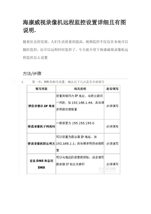
海康威视录像机远程监控设置详细且有图说明.随着社会的发展,人们生活质量的提高,视频监控不仅仅在本地可以随时监控,还可以远程时时监控了,今天就介绍下海康威视录像机远程监控怎么设置方法/步骤1.第一步:DVR的相关设置,确认以下几点是否全部填写2.第二步:端口映射(以下提供两种配置方法,两种选择一种就可以了)1、UPnP自动端口映射说明:该设置有一个要求,需要路由器支持UPnP这个功能,所以请先确认自己使用的路由器是否支持该功能,如果支持UPnP的,可以参考以下设置,如果不支持UPnP的请严格按照第2点中的端口映射来操作。
操作步骤如下:登陆路由器配置界面,开启UPnP功能,进入设备本地配置界面,启用UPn,刷新端口,看状态显示为“生效”即可。
2、路由器端口映射登陆路由器的配置界面,找到虚拟服务器(或者是端口映射),映射端口(设备默认80、8000、554三个端口,可在设备上修改,三个端口必须同时映射,缺一不可)如果在同一台路由器上有多台监控设备,请使用端口号来区分,不能重复使用端口。
3.第三步:配置自定义域名1、快捷配置点击鼠标右键,选择快捷配置->快捷上网配置勾选启用DDNS,设置设备域名(自定义,只支持小写字母、数字以及“—”且必须以小写字母开头,必填),手机号码(后续增值服务使用,必填)。
当设备状态显示在线时可以使用自动生成的访问地址来访问设备。
注意:配置海康DDNS前,需保证设备正常接入公网。
注意:1.如果设备通过路由器接入公网,需要开启路由器的UPnP功能并配置设备的UPnP参数或者在路由器上做端口映射。
2.如果配置失败,可能原因是网络不通或者域名冲突,请先检查网络,若网络正常则尝试修改其他域名2 设备访问打开IE浏览器,在地址栏直接输入/自定义域名,例如配置了设备域名为test12345,则直接输入/test12345,即可直接链接到设备登录界面。
打开iVMS-4500手机客户端,进入“设备管理”界面添加设备。
海康老款硬盘录像机手机远程访问路由设置

海康老款硬盘录像机手机远程访问路由设置一、硬盘录设置1、大家请看,此设备型号为:DS8016HC-S,为2007年购买的海康16录模拟音视频硬盘录像机2、录像机设置假设路由器网关设置为:192.168.1.1,录像机的IP设置为192.168.1.X,例如192.168.1.100;子网掩码:255.255.255.0;解析服务可以设置为114.114.114.144(不设置也可以);最重要的设置:默认为8000,修改为不常用端口,例如8111、8222、8333等;默认为80,修改为85、86等均可,因8000与80为常用端口,可能已被占用,本人实践过多次,不修改无法实现远程访问。
除以上设置,其他均无需修改。
二、局域网访问:本人用的版本是IE11 ,360浏览器无法使用。
地址栏输入:http://192.168.1.X:端口号(192.168.1.X就是录像机的IP地址,端口号是http端口号,保持和录像机设置一致),打开界面如下:录像机的用户名,以实际为录像机的密码默认为8000,修改为不常用端口,例如8111、8222、8333等;点击登陆,界面如下:点击即可预览。
三、远程访问设置:1、路由器设置,以TP-LINK举例:打开应用管理:2、能用到的就是虚拟服务器和DDNS,如图3、在虚拟服务器做端口映射,如图外部端口和内部端口对应硬盘录像机的http端口和端口。
IP地址就是录像机的地址。
4、DDNS设置DDNS就是动态域名设置,当然如果硬盘录像机所用的互联网地址为固定IP,此步可以省略。
DDNS适用于动态IP地址的情形,设置如下:服务提供者选择TP-LINK,已咨询过TP-LINK公司,目前动态域名为免费,花生壳已经收费,优先选择TP-LINK的动态域名,根据提示申请一个动态域名,格式为(xxxxxx根据自己喜好选择)。
5、最重要的,手机访问下载IVMS-4500,进入设备管理地址:1、如果是固定地址,就直接输入。
硬盘录像机设置手机监控(安卓)

Android(安卓)手机设置指导说明本说明书主要对如何在Android手机上安装、使用进行指导说明客户端软件的获取:通过我司客服或者销售人员,技术员注:其他系统手机客户端过段时间陆续会出来目前手机监控直连版程序主要功能如下:1)浏览实时视频功能;2)云台控制功能(前端是可控球机)。
支持手机的DVR参数设置参考分辨率:CIF或QCIF;帧率:5-10帧;码流类型:限定码流:64-256Kb/S注:可以根据手机性能和网络状况进行调整。
较高的手机性能和网络状况能显示更好的效果。
如果网络状况较差,可以适当降低帧率,保证流畅。
一、Android直连版使用说明:1、必备条件支持Android系统1.5版本以上,手机包括HTC G1,HTC Magic,HTC Hero,HTC G5等安装系统的手机。
2、安装及操作说明1)将vMEye.apk安装包通过数据线复制到Android手机上,在指定的目录下找到相应的.apk,点击应用程序安装(一般手机里都自带了apk安装器如果没有就需要先下载一个apk安装软件才能识别apk包),安装完就会出现程序图标,如下图:2)点击vMEye相应的程序图标,运行程序后初始界面如下图:3)点击出现如下图,首次使用或需要进行参数更改,进入参数设置界面。
如下图:注:服务器:我们公司域名:15000用户:DVR 上设置的用户名,默认是:admin 密码:DVR 上设置的密码。
未改默认:空序列号:进入DVR 机器主菜单→系统信息→版本信息→序列号。
或者打开电脑IE 进入域名:8080,登陆您的账号,在设备列表里,设备标识就是您机器的序列号!4)点击出现如图当把手机横放的时候会自动满屏播放,如下图5)连接服务器成功就可以随时随地看您的监控画面及功能键介绍7)通道切换)通道切换及功能键介绍选中相应的通道号,程序会打开相应的通道并自动播放视频。
程序默认会显示1~8通道下,当选中下一组通道按钮时,会通道号就会切换为1~8,9-16,17-24循环切换。
海康威视硬盘录像机DVRNVR远程监控设置

海康威视硬盘录像机D V R N V R远程监控设置 Company number:【0089WT-8898YT-W8CCB-BUUT-202108】海康威视硬盘录像机(DVR/NVR)远程监控设置适用设备:所有含DDNS功能的网络(DVR/)网络环境:通过路由器拨号模式1 设备配置第一步:录像机的相关设置,确认以下几点是否全部填写第二步:端口映射(以下提供两种配置方法,二选一)1、UPnP自动端口映射说明:该设置有一个要求,需要路由器支持UPnP这个功能,所以请先确认自己使用的路由器是否支持该功能,如果支持UPnP的,可以参考以下设置,如果不支持UPnP 的请严格按照第2点中的端口映射来操作。
操作步骤如下:进入设备本地配置界面,启用UPnP登陆路由器配置界面,开启UPnP功能刷新端口,看状态显示为“生效”即可。
2、路由器端口映射登陆路由器的配置界面,找到虚拟服务器(或者是端口映射),映射端口(设备默认80、8000、554三个端口,可在设备上修改,三个端口必须同时映射,缺一不可)如果在同一台路由器上有多台监控设备,请使用端口号来区分,不能重复使用端口。
第三步:配置自定义域名1、快捷配置点击鼠标右键,选择快捷配置->快捷上网配置勾选启用DDNS,设置设备域名(自定义,只支持小写字母、数字以及“—”且必须以小写字母开头,必填),手机号码(后续增值服务使用,必填)。
当设备状态显示在线时可以使用自动生成的访问地址来访问设备。
注意:配置海康DDNS前,需保证设备正常接入公网。
注意:1.如果设备通过路由器接入公网,需要开启路由器的UPnP功能并配置设备的UPnP 参数或者在路由器上做端口映射。
2.如果配置失败,可能原因是网络不通或者域名冲突,请先检查网络,若网络正常则尝试修改其他域名。
2 设备访问IE访问:手机访问:打开iVMS-4500手机客户端,进入“设备管理”界面添加设备。
设备别名处输入注册的设备域名(例如test12345),注册类型选择DDNS,DNS地址默认为,端口为80(固定填写),输入设备用户名密码,保存之后即可进入预览界面预览。
海康硬盘录像机远程监控方法(外网)以及路由器设置[1]
![海康硬盘录像机远程监控方法(外网)以及路由器设置[1]](https://img.taocdn.com/s3/m/e362e09f03d276a20029bd64783e0912a2167c3e.png)
海康硬盘录像机远程监控方法(外网)以及路由器设置[1] 海康硬盘录像机远程监控方法(外网)以及路由器设置前端视频处理设备:装有采集卡的PC 或者带网络功能的DVR 或者网络摄像机或者网络视频服务器。
网络环境:电话线+ADSL+路由器+交换机+前端视频处理设备(一般大众环境)前提条件:不管是什么视频处理设备,首先能在局域网内能访问(因为各个设备内网设置各式各样,不一一赘述)目的:能够远程监控前面在局域网能访问了,做远程就全是在路由器上设置了。
1.进入路由器,这里我用金星的这款无线路由器给大家介绍下(其他的路由器也行,只要有”转发规则“和”动态DNS“就行,这样比较方便)此主题相关图片如下:路由器界面.gif2 进入“转发规则”界面,进行端口映射,“添加新条目”;此主题相关图片如下:转发规则.gif3."添加新条目",把能在局域网访问的视频处理设备的IP和端口号填进去(各设备的IP和端口要咨询厂家,还有注意有的设备要映射多个端口,这里假设一个视频处理设备的局域网访问IP为192.168.1.121,端口为8000,协议选“ALL”有的是“BOTH”)4.“添加新条目”完成后,端口映射完成。
此主题相关图片如下:添加新条目后.gif5,设置到这里,远程监控设置已经可以实现了。
现在用ADSL 的动态IP已经可以访问了。
到路由器“运行”“WAN口状态”找外网IP6,动态IP+端口号的访问此主题相关图片如下:动态ip访问.gif7,因为动态IP容易变动,所以人们发明了域名,所以前面要选用的带“动态DNS”功能的路由器,进入路由器的“动态DNS”界面,选择“服务提供商”,填入“用户名”和“密码”(很多同胞把这里的用户和密码添混,这里应该填你申请“服务提供商”的帐户名和密码),勾上“启用DDNS”,记得“登陆”,如果成功,“连接状态”那是连接成功的,至于下面的域名信息就看你在申请的帐户上创建了,收费的免费的看君喜好,设置好后“保存”。
- 1、下载文档前请自行甄别文档内容的完整性,平台不提供额外的编辑、内容补充、找答案等附加服务。
- 2、"仅部分预览"的文档,不可在线预览部分如存在完整性等问题,可反馈申请退款(可完整预览的文档不适用该条件!)。
- 3、如文档侵犯您的权益,请联系客服反馈,我们会尽快为您处理(人工客服工作时间:9:00-18:30)。
- 用户手册V1.1 手机监控软件-直连模式 . 用户手册1 非常感谢您购买我公司的产品,如果您有什么疑问或需要请随时联系我们。
本手册适用于手机监控软件-直连模式。
本手册可能包含技术上不准确的地方、或与产品功能及操作不相符的地方、或印刷错误。
我司将根据产品功能的增强而更新本手册的内容,并将定期改进或更新本手册中描述的产品或程序。
更新的内容将会在本手册的新版本中加入,恕不另行通知。
手机监控软件-直连模式 . 用户手册 2 目录1 简
介 ................................................................................ ........................................................... 3 1.1 简
介 ................................................................................ ............................................... 3 1.2 性能概
述 ................................................................................ ....................................... 3 1.3 运行环
境 ................................................................................ ....................................... 3 1.4 约
定 ................................................................................ ............................................... 4 2 安装和准
备 ................................................................................ ............................................... 5 2.1 设备设
置 ................................................................................
....................................... 5 2.2 软件的安
装 ................................................................................ ................................... 5 3 软件运
行 ................................................................................ ................................................... 7 3.1 设备管
理 ................................................................................ ....................................... 7 3.2 预
览 ................................................................................ ............................................... 8 3.3 云台控
制 ................................................................................ ..................................... 10 手机监控软件-直连模式 . 用户手册 3 1 简介 1.1 简介手机监控软件-直连模式运行于手机平台,通过无线网络,实现对硬盘录像机、视频服务器、网络摄像机和网络球机的实时图像预览和云台控制。
通过在手机上安装手机客户端软件,可选择通过wifi 方式、或者2G/3G 实现对前端设备的访问。
若设备通过路由连入公网,则在路由器上配置设备的端口映射后,手机客户端可通过域名或者固定IP 地址进行访问;若设备连接在无线路由下,则手机客户端也可通过wifi 的方式进行访问。
1.2 性能概述手机监控客户端码流类型子码流帧类型BBP、单P帧帧率2-8帧(依赖于手机性能)分辨率QCIF 位率
32-128Kbps(依赖于无线性能)1.3 运行环境智能手机,
CPU大于200MHZ, 程序可用内存大于2M。
支持
JAVA(CLDC1.0,MIDP2.0), 支持HTTP和手机监控软件-直连模式 . 用户手册 4 Socket。
推荐windows mobile 5.0以上版本,S60 2nd 以上版本操作系统。
1.4 约定在本手册中为了简化描述,做以下约定。
手机监控软件-直连模式简称为手机客户端网络硬盘录像机、视频服务器、网络摄像机和网络球机等统一称为设备。
手机监控软件-直连模式 . 用户手册 5 2 安装和准备 2.1 设备设置使用手机客户端进行网络访问之前,首先需要对设备的网络参数和通道参数进行配置。
通过2G/3G 网络进行访问的时候,首先要保证设备已构架在公网上。
手机监控客户端连接设备的子码流进行预览,故首先需要对设备的子码流参数已进行正确配置。
可通过客户端4000V2.0 和IE 远程配置设备的编码参数。
以IE 登录配置的方式为例,首先在IE 地址栏输入设备的IP 地址,在登录界面输入用户名、密码和端口号登录设备。
选择“配置”→“通道参数”,按下表格中推荐参数进行设备参数的设置选项选择参数类型子码流帧类型单P I帧间隔8-16 视频帧率2-4 分辨率QCIF 位率上限32-64kbps 设置完成后,点击“保存”保存设置,重启设备后生效。
注:若设备不支持双码流,则通过手机客户端将无法获取到实时视频。
强烈建议按照上述参数对设备进行配置,避免手机预览图像不正常的情况。
2.2 软件的安装手
机客户端安装文件包括jad和jar文件,拷贝到手机后,打开jad文件进行客户端的安装。
手机监控软件-直连模式 . 用户手册 6 根据安装向导进行软件的安装,可选择安装手机客户端到手机存储或者存储卡中。
注:若安装到存储卡中,请保证存储卡没有加密。
否则手机重启后,手机客户端将无法使用。
选择安装路径后,进行手机客户端的安装进程。
安装完成后,将弹出安装成功的提示。
安装成功后,可看到主程序的图标,点击进入手机监控程序的主界面。
手机监控软件-直连模式 . 用户手册7 3 软件运行 3.1 设备管理软件首次运行,需要首先进行设备的添加。
点击“选项”→“设备列表”可进入设备列表界面。
点击“选项”→“设备列表”可进入设备列表界面,默认设备列表界面为空。
默认设备列表界面为空,点击“菜单”→“添加”可进行设备的添加。
完成设备信息的输入后,点击“保存”完成设备的添加。
选项说明设备名称需要添加的设备名称设备IP/域名输入设备的公网IP地址或者注册的域名端口设备的端口号用户名登录设备的用户名密码登录设备的密码接入点
选择手机与设备的网络连接方式手机监控软件-直连模式 . 用户手册8 添加成功后,设备显示在列表中。
点击“菜单”,选择“编辑”可对设备信息进行修改;点击“删除”可将选中的设备从列表中删除;点击“登录”则登录该设备进行操作。
3.2 预览选择设备登录后,则进入设备登录进度界面。
手
机监控软件-直连模式 . 用户手册9 登录成功后,则将该设备下包含的通道显示在列表中。
点击“向上”、“向下”的方向键可切换选择不同的通道;点击“向左”、“向右”方向键可切换到上一页、下一页通道列表显示。
选择需要的通道,点击“浏览”则显示当前进度。
数据获取解码后,则显示选择通道的预览界面。
点击“返回”结束预览回到通道列表界面。
手机监控软件-直连模式 . 用户手册10 3.3 云台控制通道预览成功后,如果前端连接有云台,点击“云台控制”可开启对该通道的云台控制操作。
开启云台控制后,点击“菜单”可选择控制云台的方向和变倍操作。
点击“停止云台”停止对该通道的云台控制操作。
开启云台控制后,也可通过手机键盘进行控制操作。
键盘按键说明数字键2 云台向上转动数字键4 云台向左转动数字键6 云台向右转动数字键8 云台向下转动* 变倍加# 变倍减选择“预置点调用”,进入预置点调用界面,输入已设置的预置点编号,可进行预置点的调用。