安装指导k_11479t
安装指导计划

安装指导计划【原创实用版】目录1.安装指导计划概述2.安装准备工作3.安装流程4.安装注意事项5.安装完成后的检查6.常见问题及解决方案正文一、安装指导计划概述安装指导计划旨在为您提供一套清晰、详细的安装指南,帮助您顺利完成产品安装。
本文将详细介绍安装准备工作、安装流程、安装注意事项以及安装完成后的检查等内容,帮助您在安装过程中避免可能出现的问题,确保安装顺利进行。
二、安装准备工作在开始安装前,请确保您已准备好以下物品:1.安装工具,如螺丝刀、扳手等;2.安装所需的零件和附件;3.产品说明书和本安装指导计划。
三、安装流程1.根据产品说明书,确定安装位置和空间要求;2.检查产品和附件是否齐全,有无损坏;3.根据安装图纸,进行现场测量和布局;4.开始安装,依次完成各个部分的组装和连接;5.调试产品,确保功能正常。
四、安装注意事项1.在安装过程中,请遵循产品说明书的相关规定;2.安装时请确保手头的工具和设备符合安全标准;3.避免在潮湿、高温或灰尘环境中安装;4.确保安装位置稳固,避免震动和撞击;5.切勿在未完成安装的情况下使用产品。
五、安装完成后的检查安装完成后,请进行以下检查:1.检查所有零部件是否安装牢固,有无松动现象;2.检查产品功能是否正常,如有异常请参照说明书进行调试;3.检查产品周围环境是否安全,有无潜在隐患。
六、常见问题及解决方案1.问题:安装过程中出现零部件缺失或损坏。
解决方案:核对装箱单,确认零部件数量和规格,如有缺失或损坏,及时与供应商联系。
2.问题:安装过程中,产品无法正常工作。
解决方案:参照说明书进行调试,如问题仍未解决,请联系售后服务人员。
3.问题:安装后产品出现异常噪音或震动。
解决方案:检查安装是否牢固,周围环境是否安全,如有问题,进行整改。
通过以上安装指导计划,相信您能够顺利完成产品安装。
快速安装指南

快速安装指南欢迎阅读本快速安装指南,帮助您迅速有效地完成安装。
无论您是新手还是有经验的用户,本指南将为您提供详细的步骤和技巧,帮助您顺利安装。
准备工作1. 材料准备:在开始安装前,请确保您已准备好所需材料,例如工具、零件和配件等。
安装步骤1. 确认安装位置:在开始安装前,请先选择合适的安装位置,根据需要考虑支撑能力、空间需求等因素。
2. 检查并清洁安装区域:在安装前,请确保安装区域干净、整洁,并清除任何障碍物以确保安全性。
3. 安装支撑结构:根据安装要求,安装支撑结构,确保其稳固可靠。
4. 安装关键部件:根据安装说明,逐步安装关键部件,确保正确位置对齐和固定。
5. 连接管路和线缆:根据相关说明,连接管路和线缆,并确保其连接紧固无松动。
6. 连接电源和调试:正确地连接电源,并按照说明进行系统的初步调试。
技巧与注意事项1. 阅读安装说明:在开始安装前,请仔细阅读相关的安装说明和警示标志,确保充分理解安装步骤和安全须知。
2. 使用合适的工具和设备:确保使用正确的工具和设备进行安装,以确保安全和效果。
3. 仔细检查安装质量:在每个安装步骤完成后,请进行仔细检查,确保固定牢固、连接紧密,并排除任何异常情况。
4. 考虑维护和保养:在安装完成后,请考虑设备的维护和保养,以延长使用寿命和保持性能。
故障排除如果在安装过程或安装后遇到任何问题,请参考以下故障排除步骤:1. 查阅用户手册:在解决问题之前,请先仔细查阅用户手册或安装指南,以寻找可能的解决方案。
2. 与供应商联系:如果问题仍然存在,请及时与产品供应商或售后服务团队取得联系,寻求专业支持。
总结本快速安装指南为您提供了一系列步骤和技巧,帮助您快速安装设备。
请确保在安装过程中仔细阅读并遵循安全操作指南,并始终关注安全和质量。
如果需要进一步的帮助或有任何疑问,请随时与相关专业人员联系。
祝您顺利完成安装!。
Panduit FlexFusion 服务器柜安装说明书

© Panduit Corp. 2021INSTALLATION INSTRUCTIONS V00029TKFlexFusion Server CabinetPart Number(s) : XG6*****S, XG7*****S, & XG8*****SDisclaimer:The information contained in this manual is intended as a guide for use by persons having technical skill at their own discretion and risk. The recommended practices are based on average conditions. Panduit makes no representation or warranty, express or implied, nor assumes any responsibility for the accuracy orcompleteness of these installation instructions. Panduit does not guarantee any favorable results nor assume any liability for damages, improper installation, system failures, or any other problems that could arise in connection with the use of these installation instructions.NOTE: Some views in this document may vary slightly from your actual cabinet configuration. Components missing from some views for clarity purposes.Back of CabinetFront of CabinetFlexFusion CabinetsTool List13mm Socket Wrench 15mm Socket Wrench122mm (48”) LevelT25 Torx driver6mm Hex KeyIMPORTANT SAFETY INFORMATIONSafety Notes:The maximum static weight load of the cabinet is 1588 kg (3500lbs.) The maximum weight load when the cabinet is rolling on casters is 1134 kg (2500 lbs.) The weight load should be evenly distributed across the height of the cabinet, with the heaviest components mounted at the bottom of the cabinet.The maximum operating temperature is 50º C; so that the installer is able to determine acceptability of use of accessories and components in the operating state.The equipment shall be installed or serviced by trained service personnel in accordance with the applicable requirements of the National Electric Code, ANSI/NFPA 70 or Canadian Electrical Code and the applicable sections of ANSI C2, the National Electrical Safety Code. These instructions shall not result in the risk of fire, electric shock, or injury to persons.UL Listing covers enclosure cabinet onlyTable of ContentsPackaging Material Removal (4)Leveling (5)Floor Mounting (6)Ganging Multiple Cabinets Together (7)Grounding (8)Integral Grounding (8)Equipment Rail Spacing Adjustment (9)Top Cap (10)Top Cap - Top Cap Hatch Door (11)Cable Management Fingers (12)Cable Management Fingers Locations (13)Single Hinge Door (Removal and Installation) (14)Split Doors (Removal and Installation) (15)Side Panels Removal (16)Side Panels (Removal and Installation) (17)PDU Bracket Adjustment (Removal and Installation) (18)Vertical Cable Management Panel (VCMP) (Removal and Installation) (19)Vertical Cable Management Panel KEEP-OUT Areas for Side Panel Interference (20)Packaging Material Removal• Remove all stretch wrap, protective cardboard, and plastic bag from outside of cabinet.• Remove [4] Hold Down Brackets at front and rear of cabinet.• Use at least [2] persons to carefully remove cabinet from pallet.Note:Shipping Hold Down Bracket doubles as Floor Mounting Bracket. Retain bracket for floor mounting. (see Page 6)Important:Leveling Legs must be fully retracted before the cabinet is moved into place. Sliding cabinet on leveling legs may result in damageLeveling• Ensure that (4) Leveling Legs are fully retracted.• Move Cabinet into final position.• Lower the (4) Leveling Legs until the cabinet weight is fully supported by only the leveling legs.•Adjust the (4) Leveling Legs so that the cabinet is level front-to-back and side-to-side.•• •Floor Mounting[6.2”]Ganging Multiple Cabinets Together• Ensure cabinets are level• Secure Ganging Brackets to cabinets at (2) front locations and (2) back locations• Use Ganging Brackets to cinch cabinets togetherIMPORTANT:Ensure cabinets are level by following the guidelines on page 6. Leveling the cabinet prior to ganging is important to ensure proper door operation.(4) Ganging BracketGrounding• Attach Grounding Lug or Grounding Bar to Common Bonding Network (CBN), at any of the (4) locations shown below • Grounding location is indicated by universal ground symbol near grounding lug locations.• Remove factory-installed masking tape at grounding lug location to expose unpainted surface of cabinet frame. Grounding lug or grounding bar must be assembled onto this unpainted surface (per NEC NFPA 70 Article 250.12).•Use (2) M5 x 12mm thread forming bonding screws to fasten grounding terminal to cabinet frame (torque screws to 5.1 N-m (45 in-lb)(2) Top Grounding LocationsFront and rear of cabinet Remove masking tape(2) Bottom Grounding LocationsFront and rear of cabinet Remove masking tapeIntegral GroundingTop Cap Hatch Door •Spring Clip - No grounding wires needed for Doors, SidePanels, or Top Cap components(4) Grounding locations markedwith grounding symbolEquipment Rail Spacing Adjustment• Loosen, but DO NOT REMOVE (3) M8 Hex Head Bolts at top, bottom, & center of each Equipment Rail • Adjust Equipment Rail to desired position• Use level to ensure the E-Rails remain level in thier new position• Re-tighten M8 Hex Head Bolts to 35.6N·m ± 3.5N·m [26.3 ± 2.6 ft-lbs]600mm Wide Cabinet shownInside of Cabinet• Brush Seal option - Left & right pass-thru openings with brush seals.•Bezel & Cover option - Bezel & Cover openings can be used with Panduit Cool Boot CTGN3X5 to seal around cables to prevent hot air recirculation.Top Cap600mm Wide Cabinet shownBrush Seal option1070 deep cabinets have (2) 87mm [3.4”] x 600mm [23.6”] openings 1200 deep cabinets have (2) 87mm [3.4”] x 750mm [29.5”] openings• Top Cap Hatched Door has (2) spring loaded pins that can be released in order to open door.• Top Cap Hatch Door contains (3) Brush Seal openings.• Door can be swung open and/or removed.• Hatch can be opened for installing PDU receptacle or larger devices Top Cap - Top Cap Hatch Door600mm Wide Cabinet shown Push (2) pins inward to release Hinged DoorCable Management Fingers• Push tabs of the Cable Management Fingers into diamond patterns of Cabinet E-rails.• Then push tabs of the Cable Management Fingers down to lock in place.Cable Management Fingers Locations•Follow locations shown below to install Finger KitsRU Finger 33 - 418RU Finger 28 - 335RU Finger 23 - 285RU Finger 15 - 205RU Finger 10 - 155RU Finger 2 - 108RU Finger600mm x 42RU RU Finger 35 - 438RU Finger 30 - 355RU Finger 25 - 305RU Finger 16 - 215RU Finger 11 - 165RU Finger 3 - 118RU Finger600mm x 45RU RU Finger 39 - 478RU Finger 31 - 398RU Finger 26 - 315RU Finger 18 - 235RU Finger 10 - 188RU Finger 2 - 108RU Finger600mm x 48RURU Finger 41 - 498RU Finger 33 - 418RU Finger 28 - 335RU Finger 19 - 245RU Finger 11 - 198RU Finger 3 - 118RU Finger600mm x 51RU RU Finger 37 - 425RU Finger 32 - 375RU Finger 27 - 325RU Finger 22 - 275RU Finger 17 - 225RU Finger 9 - 178RU Finger 1 - 98RU Finger700mm & 800mmx 42RU RU Finger 40 - 455RU Finger 35 - 405RU Finger 30 - 355RU Finger 25 - 305RU Finger 17 - 258RU Finger 9 - 178RU Finger 1 - 98RU Finger700mm & 800mmx 45RU RU Finger 43 - 485RU Finger 38 - 435RU Finger 33 - 385RU Finger 25 - 338RU Finger 17 - 258RU Finger 9 - 178RU Finger 1 - 98RU Finger700mm & 800mmx 48RU RU Finger 46 - 515RU Finger 41 - 465RU Finger 33 - 418RU Finger 25 - 338RU Finger 17 - 258RU Finger 9 - 178RU Finger 1 - 98RU Finger700mm & 800mmx 51RU 600 Wide Cabinets700 & 800 Wide CabinetsSingle Hinge Door (Removal and Installation)• Open Door to approximately 90°.• Lift Door off of hinges and pull away from Cabinet frame.• Reverse Steps to install Single Hinge Door.Note: Align Top pins first.Split Doors (Removal and Installation)• Open Split Doors to approximately 90°.• Lift Doors off of hinges and pull away from Cabinet frame.•Reverse Steps to install Split Doors.Note: Align Top pins first.Side Panels Removal• Upper Panel must be removed before removing Lower Panel.• Unlock Upper Side Panel and lift UP.• Swing the bottom of the Upper Side Panel out to release from cabinet.• Remove Upper PanelLowerSide PanelSide Panels (Removal and Installation)• Lift up on the Lower Side Panel and pull away from cabinet using two handles.to install Side Panels.• Reverse StepsSection Side ViewPDU Bracket Adjustment (Removal and Installation)• PDU Brackets are height adjustable if PDU spacing other than factory position is desired.• If cabinet comes with PDU Brackets installed, they can come on left side, right side, or both sides.• Reverse Steps 1 through 4when re-positioning PDU Brackets at desired positions.Slide PDU Bracket Tabs out from cabinet post Remove PDU BracketBackside ViewPDU Bracket Tabs engage the cage nutholes on vertical post of cabinet frameVertical Cable Management Panel (VCMP) (Removal and Installation)• The VCMP can be repositioned inside cabinet if position other than factory position is desired.• Disengage spring clip and lift up on the VCMP as shown below.• Reverse Steps 1 & 2 when repositioning the VCMP at desired position.Disengage spring clipVertical Cable Management Panel KEEP-OUT Areas for Side Panel InterferenceBoth sidesBoth sides1070mm WideDue to Side Panel interference, the VCMP cannot be installed 75mm (2 cage nuts over) left or right from center on 1070mm deep cabinets1200mm WideDue to Side Panel interference, the VCMP cannot be installed 50mm (1 cage nut over) left or right from center on 1200mm deep cabinetsMoving and Re-installing Vertical Cable ManagersAlign the (2) tabs at the TOP of the VCMP to the desired cage nut holes first。
安装指南说明书

Quick Installation GuideI.Package Contents:.Camera or Video Encoder .Power Adapter (only for Video Encoders and Speed Domes) .Accessories .Warranty Card.Quick Installation GuideII.Required equipments before installation.PC + Monitor .RJ-45 Network cable (1 for each device + 1 for PC).Network Switch .Power Adapter with Terminal Block (Optional) (PoE switches that are IEEE802.3af compliant can power cameras directly without adapter.For devices connected to non-PoE switches, Array please use Power Adapter with terminal block.Connect the white striped wire to 12V pin, andthe black wire to the GND pin. (See image)III.Default Settings.IP Address : 192.168.0.100 .Username: Admin .Password: 123456 IV.Accessing Your Camera – Automatic IP Setup (With Router/DHCP server)1.Connect both the PC and the device to your Network Switch with RJ-45 Network cables. Ifthis switch supports PoE, the device is already powered on. If it does NOT, please connectpower adaptor to your IP device.V.Accessing Your Camera- Manual IP Setup (Without Router/DHCP server)1.Connect the PC to the Network Switch with the RJ-45 cable, and change your PC’s IP to192.168.0.99 / Subnet Mask 255.255.255.02.Connect the device to your Network Switch. If it is a PoE enabled Switch, then the device ispowered on. If it is NOT a PoE enabled Switch, please also plug in the Power Adapter.3.Open Internet Explorer (Version 6.0 or above) at http://192.168.0.1004.When you see the login window, input default username and password:Default Username: Admin Password: 1234565.To go to the main menu, click the “Setup” button on the top left after you’ve logged in.6.For ACM/ACD models, click on “WAN settings”. Change the IP mode to Static and the IPaddress to 192.168.0.101 or any other unused IP (Avoid 192.168.0.100, the IPs of your PCsand other devices already in network.). Click “Apply”, then click “Save and Reboot”.7.For TCM/TCD/KCM/D/E/B/I models, please go to IP Settings -> Connection Type. Change toStatic IP Address and use 192.168.0.101 or any other unused IP (Avoid 192.168.0.100, theIPs of your PCs and other devices already in network.). Click “Apply” then click System ->Save & Reboot.8.Internet Explorer will close after a few seconds. This is normal.9.Wait for 30 seconds and test the new IP with Internet Explorer.10.If you have more than one device, continue again from step 2. Assign different new IP toeach camera (for instance -> 192.168.0.102, 192.168.0.103 …).If you assign the same IP to two cameras, they will be in IP conflict and will not function normally.For more details, please follow our User’s Manual.Online Customer Help Desk: /CHDACTi Knowledge Base Articles: /KB。
科勒洁具尺寸表,酒店专用
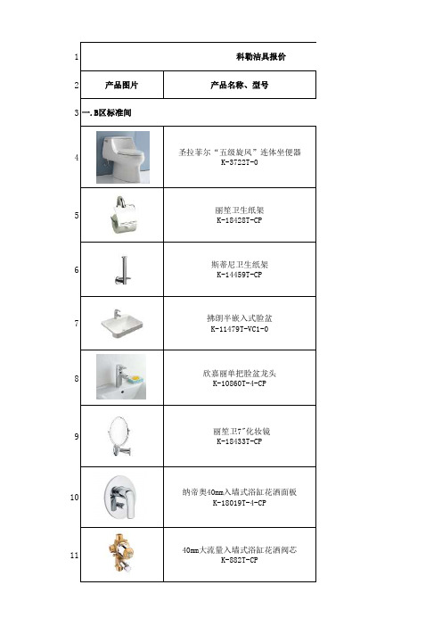
12产品图片产品名称、型号34圣拉菲尔“五级旋风”连体坐便器K-3722T-05丽笙卫生纸架K-18428T-CP6斯蒂尼卫生纸架K-14459T-CP7拂朗半嵌入式脸盆K-11479T-VC1-08欣嘉丽单把脸盆龙头K-10860T-4-CP9 丽笙卫7"化妆镜K-18433T-CP10纳帝奥40mm入墙式浴缸花洒面板K-18019T-4-CP1140mm大流量入墙式浴缸花洒阀芯K-882T-CP科勒洁具报价一.B区标准间12随心雨10" 亲氧圆形花洒K-18359T-CP13纳帝奥4功能豪华手持花洒K-18529T-CP14热带雨林天花板安装花洒臂10"K-11623T-CP15圆形花洒软管墙面连接器K-16381T-CP16标准花洒托架K-9039T-CP171.5米花洒软管K-831727-CP18 乐芙嵌入式铸铁浴缸K-9286T-GR-019浴缸排水 K-17758T20浴缸扶手 K-8243T21芙蒂缸边式浴缸花洒龙头 K-72664T-4-CP22丽笙24"双层浴巾架K-18432T-CP23直饮水龙头 3401411224陶比晾衣器K-15476T-S25斯蒂尼单衣钩K-14458T-CP26雅鼎置物架 700204827角阀DK-3102830公分软管DK-2032940公分软管 DK-2043060公分软管DK-20631法兰DK-0232入墙P型面盆去水 DK-8213122二.B区无障碍123圣拉菲尔“五级旋风”连体坐便器K-3722T-0124丽笙卫生纸架K-18428T-CP125斯蒂尼卫生纸架K-14459T-CP126帕纳奇半柱式脸盆K-17656T-0127欣嘉丽单把脸盆龙头K-10860T-4-CP128 丽笙卫7"化妆镜K-18433T-CP129纳帝奥40mm入墙式浴缸花洒面板K-18019T-4-CP13040mm大流量入墙式浴缸花洒阀芯K-882T-CP131随心雨10" 亲氧圆形花洒K-18359T-CP132纳帝奥4功能豪华手持花洒K-18529T-CP133热带雨林天花板安装花洒臂10"K-11623T-CP134圆形花洒软管墙面连接器K-16381T-CP135标准花洒托架K-9039T-CP1361.5米花洒软管K-831727-CP137 乐芙嵌入式铸铁浴缸K-9286T-GR-0138浴缸排水 K-17758T139浴缸扶手 K-8243T140芙蒂缸边式浴缸花洒龙头 K-72664T-4-CP141直饮水龙头 34014112142陶比晾衣器K-15476T-S143丽笙24"双层浴巾架K-18432T-CP144斯蒂尼单衣钩K-14458T-CP145雅鼎置物架 7002048146角阀DK-31014730公分软管DK-20314840公分软管 DK-20414960公分软管DK-206150法兰DK-02151入墙P型面盆去水 DK-8213152落地式座便器扶手DK-8811153脸盆扶手DK-8814154一字型扶手 DK-8823240三、B区三层公共区东侧卫生间241圣拉菲尔“五级旋风”连体坐便器K-3722T-0242丽笙卫生纸架K-18428T-CP243帕蒂欧自动感应小便器K-16320T-M-0244蒂梵诗台下脸盆K-2336T245菲尔法斯单把脸盆龙头K-8657T-CP246斯蒂尼单衣钩K-14458T-CP247角阀DK-31024830公分软管DK-203249法兰DK-02250入墙P型面盆去水 DK-8213251三、B区三层公共区西侧卫生间252特卡迪洛双冲坐便器墙排K-19056T-S-0253丽笙卫生纸架K-18428T-CP254帕蒂欧自动感应小便器K-16320T-M-0255蒂梵诗台下脸盆K-2336T256菲尔法斯单把脸盆龙头K-8657T-CP257帕纳奇半柱式脸盆K-17656T-0258斯蒂尼单衣钩K-14458T-CP259角阀DK-31026030公分软管DK-203261法兰DK-02262入墙P型面盆去水 DK-8213263落地式座便器扶手DK-8811264脸盆扶手DK-8814276三、B区2层餐饮包房卫生间277圣拉菲尔“五级旋风”连体坐便器K-3722T-0278丽笙卫生纸架K-18428T-CP279乔司时尚脸盆K-14800T-0280欣嘉丽单把碗盆龙头K-10861T-4-CP281斯蒂尼单衣钩K-14458T-CP282角阀DK-31028330公分软管DK-203284法兰DK-02285入墙P型面盆去水 DK-8213286三、B区1层公共卫生间287圣拉菲尔“五级旋风”连体坐便器K-3722T-0288丽笙卫生纸架K-18428T-CP289帕蒂欧自动感应小便器K-16320T-M-0290蒂梵诗台下脸盆K-2336T291菲尔法斯单把脸盆龙头K-8657T-CP292帕纳奇半柱式脸盆K-17656T-0293斯蒂尼单衣钩K-14458T-CP294角阀DK-31029530公分软管DK-203296法兰DK-02297入墙P型面盆去水 DK-8213298落地式座便器扶手DK-8811299脸盆扶手DK-8814323三、B区地下1层卫生间更衣室324圣拉菲尔“五级旋风”连体坐便器K-3722T-0325丽笙卫生纸架K-18428T-CP326乔司时尚脸盆K-14800T-0327欣嘉丽单把碗盆龙头K-10861T-4-CP328角阀DK-31032930公分软管DK-203330法兰DK-02331入墙P型面盆去水 DK-821333240mm大流量入墙式浴缸花洒阀芯K-882T-CP333 雅琦40mm 入墙式浴缸花洒面板K-6220T-4-CP334随心雨10" 亲氧花洒- 经典型K-15991T-CP335 随心雨墙面安装花洒臂19寸K-15397T-CP336 芙蒂多功能雨篷型手持花洒-节水型K-10298T -CP337 雅琦墙面连接器K-8450T-CP338雅琦花洒托架K-8451T-CP3391.5米豪华防缠绕花洒软管K-11628T-CP340三、地下卫生间341圣拉菲尔“五级旋风”连体坐便器K-3722T-0342丽笙卫生纸架K-18428T-CP343乔司时尚脸盆K-14800T-0344欣嘉丽单把碗盆龙头K-10861T-4-CP345帕蒂欧自动感应小便器K-16320T-M-0346斯蒂尼单衣钩K-14458T-CP347角阀DK-31034830公分软管DK-203349法兰DK-02350入墙P型面盆去水 DK-8213351三、SPA包房卫生间352圣拉菲尔“五级旋风”连体坐便器K-3722T-0353丽笙卫生纸架K-18428T-CP354拂朗长方形时尚脸盆K-2660T-1-0355欣嘉丽单把脸盆龙头K-10860T-4-CP35640mm大流量入墙式浴缸花洒阀芯K-882T-CP357 雅琦40mm 入墙式浴缸花洒面板K-6220T-4-CP358随心雨10" 亲氧花洒- 经典型K-15991T-CP359 随心雨墙面安装花洒臂19寸K-15397T-CP360 芙蒂多功能雨篷型手持花洒-节水型K-10298T -CP361 雅琦墙面连接器K-8450T-CP362雅琦花洒托架K-8451T-CP3631.5米豪华防缠绕花洒软管K-11628T-CP364雅鼎置物架 7002048365丽笙24"双层浴巾架K-18432T-CP366丽笙毛巾环K-18423T-CP367阿尔伯特 ARTO220C 368阿尔伯特 ARTO190C369阿尔伯特 ARTO185C 370阿尔伯特 TU170C371芬尼奥缸边式龙头K-8673-4P-CP+K-219T-CP372木桶PYT-032373斯蒂尼落地式浴缸花洒龙头K-994T-4374角阀DK-31037560公分软管DK-206376总计。
安装与操作指南

安装与操作指南安装操作系统操作系统是计算机的核心软件,安装操作系统是计算机使用的第一步。
在安装操作系统之前,需要确定所使用的操作系统版本,并检查计算机的硬件配置是否满足操作系统的最低要求。
1. 下载操作系统镜像文件:访问操作系统官方网站或其他可信赖的网站,下载适合您计算机的操作系统镜像文件。
请注意选择合适的版本和平台(32位或64位)。
2. 制作安装盘或启动盘:将操作系统镜像文件烧录到光盘或制作成启动U盘。
您可以使用常见的烧录软件或制作工具完成此步骤。
3. 启动计算机并选择安装方式:将安装盘或启动盘插入计算机,并从中启动计算机。
按照屏幕上的提示选择适当的安装方式,通常选择“新安装”或“自定义安装”。
4. 安装操作系统:按照安装向导的提示和要求,选择磁盘分区和文件系统、设置计算机的名称和密码等。
等待操作系统的安装过程完成,期间会要求您重启计算机。
5. 完成安装:一旦操作系统安装完成,您将看到操作系统的登录界面。
输入设定的密码或用户信息,即可进入操作系统。
安装并配置常用软件计算机需要安装一些常用软件来满足不同的需求,如浏览器、办公软件、音视频播放器等。
以下是一些常见的软件安装和配置指南:1. 浏览器:浏览器是日常上网必备的软件。
选择您喜欢的浏览器,如谷歌浏览器、火狐浏览器等,然后前往官方网站下载安装程序。
安装完成后,根据浏览器的提示完成简单设置,如默认搜索引擎、主页等。
2. 办公软件:办公软件用于文档编辑、电子表格和演示文稿制作等。
微软Office和LibreOffice是常见的办公软件套件。
前往官方网站下载安装程序,完成安装后根据需要进行序列号或许可证的激活。
3. 音视频播放器:音视频播放器用于播放音频和视频文件。
常见的音视频播放器包括Windows Media Player和VLC MediaPlayer等。
前往官方网站下载安装程序,按照安装向导的提示完成安装,并根据需要进行相应的设置。
4. 安全软件:为了保护计算机不受病毒和恶意软件的影响,安装安全软件是必要的。
QuickGuard 快速安装指南说明书

INSTALLATION GUIDE QuickGuard® STANDARD & EXPRESSTABLE OF CONTENT1. FOREWORD (1)2. SPECIAL NOTES (1)3. SAFETY PRECAUTIONS (1)4. FENCING DESCRIPTION (1)5. GENERAL INSTRUCTIONS (1)6. MODIFY FENCE (3)7. FENCE ASSEMBLING (5)Assemble framework (5)Fixation of infill material (13)Assembly of conventional door. (21)Assembly of sliding door. (23)8. QUICK GUARD-EXPRESS ASSEMBLY (25)9. CLEANING AND MAINTENANCE (27)10. TECHNICAL DATA (27)All given dimensions are in mm unless otherwise statedWe reserve the right to make technical changes or modify the contents of this document prior notice. With regard to purchase orders, the agreed particulars shall prevail. Troax AB does not accept any responsibility whatsoever for potential errors or possible lack of information in this document.We reserve all rights in this document and in the subject matter and illustrations contained therein. Any reproduction, disclosure to third parties or utilization of its contents – whole or in parts – is forbidden without prior written consent of Troax AB.1.FOREWORDThis installation guide describes how to assemble QuickGuard Standard fence in general.For installation of QuickGuard Express –see “QuickGuard Express Installation guide”2.SPECIAL NOTESPay attention to the following special notes in this guideImportant!A tip!3.SAFETY PRECAUTIONSAlways use adequate personal safety equipment during installation, e.g. safety googles and ear protection.Always use safety googles and ear protection when cutting aluminum profiles with a hacksaw or mitre saw, and use protection gloves when handling meshes, glass or other material that can have sharp edges.If the fence isn’t bolted to the ground, secure it temporary to p revent it from tipping over.4.FENCING DESCRIPTIONThere are two versions of QuickGuard fencing system available, QuickGuard Standard and QuickGuard Express. Both versions are aluminum systems and can be combined with each other if needed.The main difference between QuickGuard Standard and QuickGuard Express, is that Standard have a 44x44 profile between the posts and Express have a U-profile in between.QuickGuard Standard has more possibilities in terms of infill materials and adaptations.5.GENERAL INSTRUCTIONSFixation of the fence to the ground is normally done at the very end. Do not fix the fence to the floor unless vertical profiles (posts) are aligned vertically and parallel to each other.If possible, start the installation were the fence can stand free, e.g. a corner or were it can be supported temporary to a fixed part.L-brackets are used in corners, end posts, door blade etc.T-brackets are used when connecting e.g. two horizontal profiles with a post.There is no drilling or tapping needed to connect the aluminum profiles, just press the pre-assembled bracket against the profiles and loosen the screw(s) about one turn anti-clockwise. Then tighten the screw clockwise until it’s fixed.IMPORTANT!Make sure that hammer nut has turned (90°) into correct position in the aluminum profile.Lower and middle horizontal profile shall be connected to each post with one bracket, normally mounted on the side facing outwards from the machine.Upper horizontal profile shall be connected to each post with two brackets, one on the inside and one on the outside.6.MODIFY FENCEQuickGuard can easily be adapted and modified on site. Aluminum profiles, polycarbonate sheets, steel mesh e.t.c. can easily be cut without using any tools that generate heat (=no fire risk).•Avoid tools that can generate heat and cause a fire, e.g. angle grinder.•Make sure that material to be cut is adequately supported and clamped during the cutting operation.•Use adequate personal safety equipment.Cut meshWhen cutting the welded mesh the wire ends should be at least 15 mm or cut flush to the joining wire.DIMENSION TABLE FOR INFILL MATERIALSExampleA polycarbonate sheet shall be cut to fit an opening where A=1500 and B=800. According to the dimension table the sheet should be 1520 (1500+20) x 820 (800+20).7.FENCE ASSEMBLINGAssemble frameworkSTEP 1.Pre-mount floor brackets on to the post profile according to example pictures below. Make sure that bottom part of the floor bracket aligns with the profile end before tightening the fixation screws. Also, make sure that hammer nuts are positioned correctly inside the profile.Note!At least two (2) floor brackets shall be used on each postMark where the fence will be installed. Use a chalk line to get a straight line as a reference.STEP 3.Mount lower horizontal profile on to a post. Make sure that distance between floor and lower part of the horizontal profile is correct, and that hammer nuts are positioned correctly inside the profile.Note!Post must be mounted so that floor brackets are perpendicular to the fence.TIP!Use a spacer block to facilitate installation and mount the horizontal profile in correct position.Mount next post on to the horizontal profile. Use a spacer block to place the profile in correct position.Polycarbonate sheetTear off a small area of the protective film from both sides of the polycarbonate sheet (fig1), and insert infill material in lower part. Bend the sheet (fig.2) and/or press the post apart to insert the sheet in to the profile T-slot.Tip!Leave the protective film on as long as possible to prevent damages on the surface.MeshBend the mesh and/or press the post apart to insert the mesh in to the profile T-slot. Make sure that the mesh is oriented with the vertical wires facing closest to the outside.Steel panelBend the steel panel and/or press the post apart to insert the mesh in to the profile T-slot. The convex side of the steel panel should be facing outwards.If steel panel shall be secured with infill securing strip (JSM PL1_) and cellular rubber (JSM G2), cellular rubber have to be mounted on to the steel panel before inserting the steel panel in to the frame work. Cellular have to beLaminated glass 6,4mmMount rubberstrip (JSM G3) all around the glass.Fig.1 Fig.2 Fig.3Place the middle horizontal profile between the posts and press it down against the polycarbonate sheet. Lift the middle horizontal profile ~3mm and fix it with L-brackets. Make sure that distance between the two horizontal profiles are correct. It shall be possible to move the infill material ~3mm vertically and horizontally when profile is fixed.Mount the rest of the fence…3. 4.5. 6.7. 8.11. 12.13.Position the fence on the floor and make sure that door posts are aligned vertically and parallel to each other before fixing the fence to the floor. Use adequate fixation bolts and center the drill in the fitting holes (fig.1)Note!Make sure that posts are in line with each other and that door posts are parallel before fixing the fence to the floor.Fixation of infill materialSelection of fixation componentJSM PL1_ / -PL2_Infill securing stripJSM PL3 Panel lockJSM NL3 Net lockJSM G2 Cellular rubber 5x20mmProduct W JSM PL1_ 6,5 JSM PL2_7,5Polycarbonate sheetTear and fold up about 100mm of the protective film all around the sheet, on both sides before securing the sheet in the frame work.3mm thicknessUse infill securing strip (JSM PL1_) together with cellular rubber (JSM G2) or panel lock (JSM PL3) to secure the sheet in the frame.4mm thickness.Use infill securing strip (JSM PL2_) or panel lock (JSM PL3) to secure the sheet in the frame.5mm thicknessUse infill securing strip (JSM PL1_) or panel lock (JSM PL3) to secure the sheet in the frame.Fixation with panel lock JSM PL3Panel lock JSM PL3 is normally mounted from the outside of the fence, on all four sides. Mount panel lock evenly distributed every 300-400mm starting maximum 250mm from corner (fig 1). Tighten the torx (T25) screw so it penetrates the polycarbonate surface about 2mm, max torque 3Nm.Use a cordless drill machine with torque control when mounting panel lock.Fig 1Fixation with infill securing strip JSM PL1_ or JSM PL2_Infill securing strip JSM PL1_/-PL2_ is normally mounted from the outside of the fence, on all four sides. JSM PL1_/-PL2_ is available in a few pre-cut lengths as listed in table 1 below. Any other length has to be cut on site. Length should be about 2mm shorter than the distance between the connecting profiles.Table 1Laminated glassThe glass is mounted with a u-rubber strip (JSM G3) in the profile groove. Rubber strip should be mounted all around the glass, before the glass are inserted in to the frame work.• Use protection gloves. • Carry the glass upright• It’s recommended to be two persons handling the glass.Fig.1Mounting the rubber stripL= (L1+L2) x 2 + 50 Step 2Make a 90° V-cut out from the rubber stripStep 3Mount the rubber strip on to the edge of the glass. Step 4Fold the rubber strip and press it on to next edge.Step 5Make a new V-cut and press it on to the next edge.Step 6Mounting laminated glass and sound absorbing panel1.Premount vertical profiles with floor brackets by first loosening the screw anti-clockwise. Then tighten the screw clockwise in the usual way. A spacer between the floor and the lower horizontal profile will make the installation easier.3.Insert the sound absorbing panel (1) in to the frame and put the horizontal profile above (2). The perforated side of the panel should normally be facing towards the sound source.5.Insert the glass (1) in to the frame and put the upper horizontal profile above (3). 2.Assemble mounting profile JSM AS1 all around the panel. The profile should be fixed on to the panel. If it’s to loose, increase the slot a little by pressing the “walls” together.4.Assemble the U-rubberstrip (JSM G3) all around the glass.6.Insert next sound absorbing panel at the same way as described previously, see step 2 and 3 above.7.Insert next glass same way as described previously, see step 4 and 5 above.8.Fix the profiles with L- and T-brackets, two brackets on the upper part (inside and outside) if possible, and one bracket on the other parts, normally on the outside.9.Adjust the fence and fix it to the floor with accurate fixations.Normally two (2) floor brackets are used per post and then fixed with one (1) bolt per floor bracket. If only one (1) floor bracket is used per post, both (2) fixation holes must be used.Assembly of conventional door.1) Install and fix fence to ground. Mount L- and T-brackets (JSM 32B-K & JSM 33B-K) on both sidesof the fence on the top. Make sure the door posts are paralell to each other before fixing them to the ground.2) Premount the door. Mount L-brackets (JSM 32B-K) on both sides on corners.3) Open the hinges for access to the screws. Put the door on the ground in the opening and mount the hinges onto the fence. Make sure that nuts turn out correctly and lift the dorr to correct hight and then tighten the screws,4) Mount door stops (JSM D13A) and eventual safety switches.Assembly of sliding door.1) Install and fix fence to ground. Mount L- and T-brackets (JSM 32B-K & JSM 33B-K) on both sides of the fence on the top. Make sure the door posts are paralell to each other before fixing them to the ground.2Premount the sliding door. Slide in the suspension wheels (JSM D5) into the 44x44 profile before putting on the endcaps (JSM L1B). Mount L-brackets (JSM 32B-K) on both sides on corners.3) Mount guiding components (JSM D12 & JSM D12A) onto the fence.4) Take the premounted door blade and slide it in to the guiding rail and guiding components.5) Mount door stops (JSM D13 & JSM D13B) and eventual safety switches.8.QUICK GUARD-EXPRESS ASSEMBLY9.CLEANING AND MAINTENANCECleaningAluminium profiles (anodized)•Use a mild neutral detergent (pH 6-8) and/or waterPolycarbonate sheets•Use a mild soap solution and a soft cloth.•Do not use abrasive or highly alkaline cleaners.•Never scrape the sheet with squeegees, razor blades or other sharp instruments.•Do not clean sheet in hot sun or at elevated temperatures as this can lead to staining.10.TECHNICAL DATA。
快速安装指南说明书

Quick Installation GuideCTT050 CTT049 CTT048 CTT055Bypass trayCTT063CTT032CTT033CTT074CTT075CTT029Loading Papertray1CTT062CTT148CTT300CTT073Read this manual carefully before you use the product and keep it handy for future reference. For safe and correct use, please be sure to read the Safety Information before using the machine. This manual briefl y describes the procedure for installing this machine. For more details about other information, see User Guide in the CD-ROM.Place to InstallSP 200SF/201SF/202S/202SF10 cm(4.0”)45 cm (17.8”)20 cm (7.9”)20 cm (7.9”)40 cm (15.8”)SP 200S/201S10 cm(4.0”)45 cm (17.8”)10 cm (4.0”)20 cm (7.9”)40 cm (15.8”)SP 200/200N10 cm(4.0”)45 cm (17.8”)10 cm (4.0”)20 cm (7.9”)40 cm (15.8”)Power Source220-240 V, 50/60 Hz, 5 AUnpackingRemove the adhesive tape.CTT054CTT096CTT045Installing the Driver for USB and Reading the ManualCXP065CXP066CXP067CXP068CXP069Connection123CTT0931. Port For Handset2. Port For External Telephone3. Port For LINECTT071CTT144CTT097 Using the Fax FunctionSP 200SF/201SF/202SF OnlyConnecting the HandsetCTT143CTT052CTT064CTT078ConnectionFor details about specifying network settings, see "Software Installation Guide".CTT136CTT13712CTT139Selecting the TelephoneLine TypePress the [] key.CTT006Press the [▼] or [▲] keys to select [FaxFeatures], and then press the [OK]key.Press the [▼] or [▲] keys to select[Comm. Settings], and then press the[OK] key.Press the [▼] or [▲] keys to select[Dial/Push Phone], and then press the[OK] key.Press the [▼] or [▲] keys to select thetelephone line type appropriate foryour telephone service, and then pressthe [OK] key.Press the [] key to return tothe initial screen.Selecting the TelephoneNetwork Connection TypePress the [] key.Press the [▼] or [▲] keys to select [FaxFeatures], and then press the [OK]key.Press the [▼] or [▲] keys to select[Comm. Settings], and then press the[OK] key.Press the [▼] or [▲] keys to select[PSTN / PBX], and then press the [OK]key.Press the [▼] or [▲] keys to select[PSTN] or [PBX], and then press the[OK] key.Press the [] key to return tothe initial screen.Setting the Outside LineAccess NumberIf you have selected PBX, use the followingprocedure.Press the [] key.Press the [▼] or [▲] keys to select [FaxFeatures], and then press the [OK]key.Press the [▼] or [▲] keys to select[Comm. Settings], and then press the[OK] key.Press the [▼] or [▲] keys to select [PBXAccess Number], and then press the[OK] key.Enter the outside line access numberusing the number keys, and then pressthe [OK] key.Press the [] key to return tothe initial screen.Basic Operation forSending a FaxPress the [] key.CTT102Place the original on the exposure glassor in the ADF.Enter the fax number using the numberkeys.Press the [] key.When you place original on the exposure glassand Memory Transmission mode is enabled,perform the following steps to scan the subse-quent pages of the original.Press the [1] key within 60 seconds,place the next original on the exposureglass, and then press the [OK] key.Repeat this step until all originals are scanned.Press the [2] key to start sending thefax.© 2013EN CN M133-8697Quick Installation Guide。
- 1、下载文档前请自行甄别文档内容的完整性,平台不提供额外的编辑、内容补充、找答案等附加服务。
- 2、"仅部分预览"的文档,不可在线预览部分如存在完整性等问题,可反馈申请退款(可完整预览的文档不适用该条件!)。
- 3、如文档侵犯您的权益,请联系客服反馈,我们会尽快为您处理(人工客服工作时间:9:00-18:30)。
55
55
55
45
45
45
335 462
Length Width Height Depth Outer
·
578 548 462 335 172 126
Inner
·
K-11479T-VC1
K-11479T-VC4
K-11479T-VC8
U-Washer U Countertop Bolt Washer Butterfly Nut
1211039-T01-A , 2012 ã ã Copyright Kohler China Ltd., 2012
Cutting line of the cabinet top. Please adjust according to the specific cabinet top.
302mm
548 578
· · · · · · ·
TOOLS AND MATERIALS
Countertop
R8
Cut this area into a round rim
· · · · · · · · · · · · ·
(
)
(Not Supplied)
· · · · · · · · · · · · · Template(supplied) Safety glasses Pencil Scissors Tape measure Putty knife Plumbers putty Hacksaw Keyhole saw or saber saw Drill (14mm drill bit) Adjustable wrench Pipe wrench Tubing cutter
Carefully position the lavatory in the cutout, and press down firmly, mount the washer and rubber gasket in sequence beneath the countertop, and tighten the butterfly nut with hands.
Cut along this line
· · ·
· · ·
· · ·
· · ·
Observe all local plumbing and building codes. Inspect the waste and supply tubing; replace if necessary. Prior to installation, unpack the new lavatory and carefully inspect it for damage. Return the lavatory to its protective carton until you are ready to install it. For replacement installations, make sure the existing cutout is the same or smaller size as the new lavatory. Use the template supplied with the lavatory to mark correct size cutout. Kohler lavatory is made according to American National Standard that it can match the American lavatory fittings . Any other lavatory fittings may not fit for kohler lavatory.
548 578
548 578
Bo ho lt mo le un tin g
CAUTION: Risk of personal injury or product damage. Large lavatories are very heavy. Get help lifting the lavatory into place.
· · · ( )
2
14
· · ·
· · · · · · ·
· ·
· ·
· · 2 ·
· · ·
Cut the template on the cutout line. Position the template on the countertop to ensure clearance between the lavatory, faucet, and backsplash. Please fold the front end according to the marked folding line. Verify cabinet clearance beneath the countertop. Trace the template on the countertop with a pencil. Please do not surpass the folding line. Mark the center position of 2 bolt mounting holes. Re-check the clearance between the lavatory, faucet, backsplash, and cabinet. Adjust the template accordingly. Drill two 14 holes in the centre of countertop bolt holes. Cut the opening in the countertop along the inside edge of the pencil line. Please cut the cabinet according to the lines on the template. Be sure to cut along the inner side of the lines and do not surpass the front cutting lines. If the cabinet top is not flush with the countertop, please adjust the cutting lines of the cabinet top accordingly. Set the U-washer on the bolt and install into the groove. Temporaily position the lavatory in the opening, make sure the bolts are fixed through the countertop mounting holes, and adjust to proper position. CAUTION: Risk of personal injury or product damage. Large lavatories are very heavy. Get help lifting the lavatory into place.
· ·
U
· ·
Immediately wipe away any excess sealant, and fill any voids as needed. Verify that the lavatory has not moved out of position. Allow the sealant to cure for at least 30 minutes before proceeding. Connect the faucet supply lines. Connect the drain assembly. Open the faucet valves, and check for leakage. Clean up with a non-abrasive cleaner.
Folding line
Do not use the product in the water below 0 C.
Butterfly Nut
o
Rubber Gasket
* / B45.1-08 *
GB6952-2005 ASME A112.19.2-2008/CSA
* The product conforms to GB6952-2005, ASME A112.19.2-2008 and CSA B45.1-08. Please choose faucets that accord with these standards. * Kohler faucets are recommended.
R8
Countertop
(
14mm
)
550mm
Cut this area into a round rim
Folding line
Outside rim of the countertop
IMPORTANT CONSUMER INFORMATION (CARE AND CLEANING)
To keep your lavatory looking new, make sure you rinse it out thoroughly after each use. DO NOT USE ABRASIVES on this product, as they will scratch and ruin the surface. Stubborn stains, paint, or tar can be removed with turpentine or paint thinner. 0C
K-11479T-VC1/VC4/VC8 FOREFRONT
ROUGHING-IN
102 3- 32 204 3- 35