欧姆龙hv-f021说明书==
欧姆龙液位开关说明书

开关液位设备概要选择机型的标准故障检查液位设备Q&A关于施工资料参考电极式液位开关(61F)作为电气性液位检测方式,被广泛用于以大厦、集中住宅的上下水道为主及钢铁、食品、化学、药品、半导体等各种工业、农业水、净水场、污水处理等的液面控制。
一旦电极接触到液体,通过液体可以闭合电路(电气流通的道路),根据流过的电流检知液位控制的动作原理,是以所谓的导电性液体为控制对象的液位开关。
进行检测时,直接检测液体的电极间电阻,根据大于或小于已设定的电阻值,来判断有无液面。
■基本原理以一般接收上水道供水的情况为例来进行说明。
通常,在大厦、集中住宅区等中,一旦接水槽接收供水后,就会将水送到设置在屋顶上的高架水槽内,然后再分配到各楼层。
在高架水槽内,如果因水的消耗而导致水槽内的水位下降,通过泵从接水槽中再进行补充。
达到一定的水位后,即可停止泵了。
(参照图1)在高架水槽内,可以进行水位的控制,以保持上限和下限间的水位。
可以根据下列工作原理来进行这一水位控制。
图1. 水槽的供水控制●根据水位对泵进行ON、OFF控制(2根电极式)①如图2,电极E1未接触到液面时,电流流通的电路(E1-E3间)为开路,没有电流通过。
因此,继电器「X」不动作,继电器「X」的接点仍为“b侧”。
②如图3,电极E1接触到液面时,为电路闭合状态(液体将E1-E3间闭合),因此,继电器「X」动作,接点移动到“a侧”。
若将该继电器接点连接到接触器,则可根据液面的位置对泵进行ON、OFF控制。
但是,如图2、图3,如果仅有2根电极,电极E1附近会发生波动,导致继电器抖动。
为此,电极式液位开关有自我保持电路。
(图2、图3用于水位的报警等方面)图2 水位低时图3 水位高时●带自我保持电路的实用性水位控制(3根电极式)如图4所示,使用E1、E3电极以外的E2电极,通过a2接点连接E2、E1。
此时(前页的②)液面接触电极E1、继电器「X」动作,如果接点变为“a侧”,即使接下来液面低于E1,E2-E3间的电路也可以保持闭合状态。
欧姆龙伺服电机
0./6$(
$90OF7
$9%SJWF
1$ 1-$
$9%SJWF
/$
0./6$(
OMNUC G
3
8 L8
3000 2000 1000
50W 300W 900W 1kW 3kW 5kW 6kW 7.5kW
7.5kW
1500r/min
(r/min)
'2.
4:4."$$4
3"$$(1
$48.$7.$7
'2..."
98;ƾƾƾ+"ƾ 98#ƾƾ+ƾƾƾƾ 98;ƾƾƾ+#ƾƾ
$+8/$ $+8/$
$48/$ $48/$
4#$&$#
0./6$( /
7
AC伺服电机/驱动器[OMNUC G系列 脉冲,通用输入型]
R88M-G□-Z/R88D-G□□-Z
可对应位置控制、速度控制、转矩控制等各种用途
· 高速·高响应性能 提升了以往的W系列AC伺服电机/驱动器的性能,实现了速 度响应频率(1kHz的高速响应)。
$/
$/
#
""
#
$48)$17
98ƾ(ƾ
98;ƾƾƾ+#
4:4."$$1)$1-
'"
$90OF
$91SPHSBNNFS
$91PTJUJPO
8 AC伺服电机/驱动器[OMNUC G系列 脉冲,通用输入,网络型]R88M-G□-Z/R88D-G□□-□-Z
"$
3.(ƾ; 3%(ƾƾƾ;
欧姆龙PLC驱动产品规格说明书

欧姆龙PLC驱动产品规格说明书(本说明书说明驱动产品的功能,性能指标,是测试工程师、文档工程师和开发人员交流的重要依据,是编写测试用例和帮助文档的重要依据。
下边几项是必须填写的,如果还有需要说明的部分,需要编写更多的内容)[修订记录][项目经理填写]一、产品功能简介a)硬件功能概述(简要说明硬件设备功能):欧姆龙PLCb)支持协议说明(说明支持的协议,特别是针对多协议的设备一定要说明该驱动支持哪种协议,对协议支持到什么程度)欧姆龙HostLink协议(包括C-mode指令和FINS指令)此次是对旧有驱动的升级,对旧有驱动作如下修改:1. 对CS1系列和CJ1系列PLC的DM区增加批量写的功能2. 对CJ1系列和CS1系列PLC去掉TSV和CSV寄存器,因为这两个系列的PLC中并没有对应的TSV和CSV内存区3. 增加了国际化支持c)支持的硬件型号说明:支持C系列、CS1系列、CJ1系列、CV系列二、驱动接口:(3.0开发包 3.0以前的开发包开发配置工具)(程序员必须填写,对于3.0开发包的编程规范参加附录,测试工程师按下面的规范要求执行测试)三、设备添加方式a)在组态王中定义设备时请选择:组态王定义设备时请根据所选用的PLC的具体型号定义设备[PLC] > [欧姆龙] > [C Series] > [HostLink][PLC] > [欧姆龙] > [CJ1] > [HostLink][PLC] > [欧姆龙] > [CS1] > [HostLink][PLC] > [欧姆龙] > [CV Series] > [HostLink]英文版设备列表路径:[PLC] > [OMRON] > [C Series] > [HostLink][PLC] > [OMRON] > [CJ1] > [HostLink][PLC] > [OMRON] > [CS1] > [HostLink][PLC] > [OMRON] > [CV Series] > [HostLink]本次测试是用C Series系列PLC进行测试b)c)四、本设备的地址格式及地址范围有两种连接方式,直连和通过网络连接,因此地址格式有2种1直通:nUnitNo2网络连接:nUnitNo:DNA.DA1.DA2nUnitNo:与上位机直接相连的PLC的HostLink单元号,取值范围0~31DNA:PLC所在网络的FINS网络号,取值范围0~127,通过PLC编程软件可以设置DA1:PLC所在网络的FINS节点号,取值范围0~62,通过PLC编程软件可以设置DA2:PLC所挂接的模块的单元号,必须为0,即只能读写CPU单元的数据注意:1. 若是通过PLC与其它的PLC通信也就是通过FINS网络,则要采取nUnitNo:DNA.DA1.DA2这种格式,这种情况下,与计算机直连的PLC不能是C系列PLC,因为C系列的不支持网络连接功能。
欧姆龙产品更新说明说明书

更新于2013年4月BEST第16版光电传感器PA-125,E3F3-R61/R81传感距离不是2m,应改为3m。
定时器PE-40,H3CR-F8的CAD文件中应该是与P2CF-08组合。
PE-44,与P3G-08配合使用的适配器型号是Y29F-30,应是Y92F-30。
PE-48,H3CR-HRL嵌入式安装的底座是P3G-08,应是P3GA-11。
PE-106,H3CA-8H、H3CA-8H-306有1c限时接点,应是1c限时接点、1c瞬时接点。
开关电源PG-71,本体表格中容量应该是300W和600W,不是30W和60W。
BEST第17版液位设备P-58,动作说明中应是水面升到E1以上时(U1的LED灯亮)。
P-72,LL1和BL1应该是高架水槽缺水。
P-81,E2下限用改为中间用,E1下限用改为上限用P-93,内部连接图中:61F-HSL的表面连接用底座应是8PFA。
P-718,附表1、2中的固有电阻改成电阻率,附表1A中的电导改成电导率。
微动开关P-149,摆杆型、小型线型摆杆型的OP小,OP中,OP大,应该是OF小,OF中,OF大。
P-190,1VAP2-6应是1VAP2-2,1VAP2-2应是1VAP2-6。
P-193,XAA-1的动作特性图中回复力应是动作力,预行程应是回复力。
限位开关P-252,命名规格2中,CL-2、CL-2N是“可调式滚珠摆杆型”错误,应该是“可调式棒式摆杆型”。
P-253,WLI/O连接器型⑤配线规格中的 -M1JB不是“2芯,DC规格、NO配线、连接器查缴No.3、2”,应改为“NC配线”。
P-254,WLD3应是顶部球式柱塞型。
P-255,第二张表格中驱动杆种类前两个“可调式滚珠摆杆”错误,应该是“可调式棒式摆杆”。
P-268,导线规格表格中标准应为5m。
P-281, WL-3A200的长度应该是417.5mm,不是412.5mmP-295,D4A-D00对应的驱动杆的种类不是“可调式滚珠·摆杆型”,应该改成“可调式棒式·摆杆型”。
Omron LC2H数字计数器产品说明书
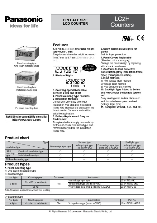
Product types1. Panel mounting type1) One-touch installation typePanel mounting type One-touch installation typePanel mounting type Installation frame typePC board mounting typeFeatures1. 8.7 mm .343 inch Character Height (previously 7 mm)Easy-to-read character height increased from 7 mm to 8.7 mm .276 inch to .343 inch .2. Plenty of Digits3. Counting Speed Switchable between 2 kHz and 30 Hz4. Panel Mounting Type Features2 Installation MethodsComes with very easy one-touch installation type and also installation frame type that uses the bracket on the timer/counter. Choose a method that suits the application.5. Battery Replacement Easy on EnvironmentT o replace battery simply remove body for the one-touch installation type, and remove battery lid for the installation frame type.6. Screw Terminals Designed for SafetyBuilt in finger protection.7. Panel Covers Replacable (Standard color is ash gray.)Change the panel design by replacing with a black panel cover.8. Conforms to IP66 ProtectiveConstruction (Only installation frame type.) (Front panel surface)9. Input Methods1) Non-voltage input method 2) Voltage input method3) Free voltage input method10. Backlight Type Added to Series and Now 2-color Switchable (green/red)Easy viewing even in dark places and switchable between green and red (Voltage input type).11. Compliant with UL, c-UL and CE.RoHS Directive compatibility information/Product chart2) Installation frame typeSpecificationsNotes)1.The value given for battery life is calculated based on continuous operation (count input signal ON/OFF = 1:1), therefore, this value is not guaranteed.Also, battery life is decreased 30% when operation is continuous with 2 kHz count inputting in 2 kHz mode.2.Operation is at 25 Hz when using 24 V AC.3.Only for installation frame type.Applicable standardPart names1. Front reset buttonThis button resets the count value. It does not work when the lock switch is ON. Be aware that battery life willdecrease if this switch is used frequently.2. Lock switch (Refer to chart on right.)Disable the front reset button.Note)T urn ON at the LCD side (reset disabled) andOFF at the terminal block side (reset enabled).3. Count speed switch (Refer to chart on right.)Use this switch to switch the count speed between 30 Hz and 2 kHz. (On the non-voltage and voltage input types, 30 Hz is on the LCD side and 2 kHz is on the terminal block side. Fixed at 30 Hz for free voltage input type.)Note)Y ou must press the front reset button when youchange the count speed switch setting.Confirm, however, that the Lock Switch is OFF (front switches operable).Notes)1.❇Default setting when shipped.2.Make the switch setting before installing to panel.Dimensions1. Panel mounting type • External dimensions1) One-touch installation typemm inchGeneral tolerance: ±1.0 ±.039• Panel installation diagramNote)When installing to a 4.5 mm .177 inch thick panel, remove the rubber spacerfirst.When installing the one-touch installation type model, make sure that the installation spring does not pinch the rubber gasket.T o prevent the installation spring from pinching the rubber gasket:1. Set the rubber gasket on both ends of the installation spring (left and right).2. Confirm that the installation spring is not pinching the rubber gasket, and then insert and fix the installation spring in place from therear of the timer unit.• Terminal layout and wiring diagrams2) Installation frame type• Panel mounting diagramMounting screwsMounting frame • Panel cut-out dimensionsThe standard panel cut-out is shown below.Use the mounting frame (ATH3803) and the rubber packing (ATH3804).(Only installation frame type.)• For connected installation (sealed installation) (Only installation frame type.)Notes)1. Suitable installation panel thickness is 1 to 4.5 mm .039 to .177 inch .2. Waterproofing will be lost when installing repeatedly (sealed installation).A=(1.890×n-.098)0+.0390Input methodNotes)1.2 and 4. (The input and reset circuits are functionally insulated.)2.When using transistor (T r) input, use the right as a guide. (Collector withstand voltage Q 50 V , leakage current < 1 µA)3.Be aware that the application of voltage that exceeds the voltage range of the H level to the count input terminal, and the application of voltage to the reset input terminal, can cause damage to the internal elements.2. PC board mounting type • External dimensions• Terminal layout and wiring diagramsGeneral tolerance: ±1.0 ±.039 mm inchPC board pattern (BOTTOM VIEW)General tolerance: ±0.1 ±.004Note: The AXS212811K is recommended as a compatible connection socket.0.3.012±.004Q -E , }-w , e -t and S -F are connected internally.An external power supply is required.Connection sockets 28 pin DIP terminalNotes)1.Do not reverse the polarities when connecting the DC voltage for the backlight.2.2 and 4. (The input and reset circuits are functionally insulated.)3.When using transistor (T r) input, use the right as a guide. (Collector withstand voltage Q 50 V , leakage current < 1 µA)4.Be aware that the application of voltage that exceeds the voltage range of the H level to the count input terminal, and the application of voltage to the reset input terminal, can cause damage to the internal elements.Explanation of operation1. Counting takes place when the count input signal is ON.2. Counting resumes again when the count value reaches 99999999 (full scale value) and then returns to “0” with a new count input.3. No measurement takes place when a reset is input.1) When reset is ON, resetting takes place and the count becomes “0”.2) Press the front reset button when you want to reset manually (only panel installation type).Note)Be aware that battery life will decrease if thecount input or reset input are left ON.Note) ❇Count becomes “1” when the reset input is turned OFF while the count signal is being input.Cautions for use1. Non-voltage input typeFor both panel mounting and PC board mounting types1) Never apply voltage to the non-voltage input type. This will damage the internal elements. Also, since there is a possibility of erroneous operation, do not connect in parallel the inputs of a non-voltage input type and another counter from a single input signal.2) Since the current flow is very small from the count input and reset input terminals (1 and 3 on the panel mounting type and terminals e to t and S to F on the PC board mounting type) please use relays and switches with high contact reliability.3) When inputting with an open collector of a transistor, use a transistor for small signals in which ICBO is 1 µA or less and always input with no voltage.4) When wiring, try to keep all the input lines to the count and reset inputs as short as possible and avoid running them together with high voltage and power transmission lines or in a power conduit. Also, malfunctions might occur if thefloating capacitance of these wires exceeds 500 pF (10 m 32.808 ft. for parallel wires of 2 mm2). When using 2 kHz mode, use with a wiring floating capacitance of 120 pF (3 m 9.843 ft. for parallel wires of 2 mm2). In particular, when using shielded wiring, be careful of the capacitance between wires.PC board mounting type1) For external power supply use manganese dioxide or lithium batteries (CR type: 3V).2) Always reset after external power is applied and confirm that the display reads “0”.3) Make the wiring from the battery to the counter unit as short as absolutely possible. Also, be careful of polarity.4) Calculate battery life with the following formula.t = A/It: battery life [h]I: LC2H current consumption [mA]A: battery capacity until minimumoperation voltage is reached [mAh] 5) Hand solder to the lead terminal. Do not dip solder. With the tip of the soldering iron at 300°C 572°F perform soldering within 3 seconds (for 30 to 60 W soldering iron).2. Voltage input type1) Be aware that applying more than 30 V DC to count input terminals 1 and 2, and reset input terminals 3 and 4 will cause damage to the internal elements.2) For external resetting use H level(application of 4.5 to 30 V DC) betweenreset terminals 3 and 4 of the rearterminals. In this case, connect + toterminal 3 and – to terminal 4. This isthe valid polarity; therefore, the counterwill not work if reversed.3) When wiring, try to keep all the inputlines to the count and reset inputs asshort as possible and avoid running themtogether with high voltage and powertransmission lines or in a power conduit.Also, malfunctions might occur if thefloating capacitance of these wiresexceeds 500 pF (10 m 32.808 ft. forparallel wires of 2 mm2).3. Free voltage input type1) Use count input terminals 1 and 2 forfree voltage input and reset terminals 3and 4 for non-voltage input.2) Be aware that the application ofvoltage that exceeds the voltage range ofthe H level to the count input terminal,and the application of voltage to the resetinput terminal, can cause damage to theinternal elements.3) Since the current flow is very smallfrom reset input terminal 3, please userelays and switches with high contactreliability.4) When inputting a reset with an opencollector of a transistor, use a transistorfor small signals in which ICBO is 1 µA orless and always input with no voltage.5) T o reset externally, short reset inputterminals 3 and 4 on the rear.6) Input uses a high impedance circuit;therefore, erroneous operation may occurif the influence of induction voltage ispresent. If you plan to use wiring for theinput signal that is 10 m or longer (wirecapacitance 120 pF/m at normaltemperature), we recommend the use ofa CR filter or the connection of a bleederresistor.4. How to reset multiple panelmounting type counters all at once(input is the same for count)Non-voltage input typeNotes)e the following as a guide for choosingtransistors used for input (Tr).Leakage current < 1 µAe as small a diode (D) as possible in theforward voltage so that the voltage betweenterminals 3 and 4 during reset input meetsthe standard value (0.5 V).( At IF = 20 µA, forward voltage 0.1 andhigher.)Voltage input typeNote)Make sure that H (reset ON) level is at least 4.5V.5. Backlight luminanceT o prevent varying luminance amongbacklights when using multiple Backlighttypes, please use the same backlightpower supply.6. Environment for use1) Ambient conditions• Overvoltage category II, pollution level 2• Indoor use• Acceptable temperature and humidityrange: –10 to +55°C, 35 to 85%RH (withno condensation at 20°C)• Under 2000 m elevation2) Use the main unit in a location thatmatches the following conditions.• There is minimal dust and no corrosivegas.• There is no combustible or explosivegas.• There is no mechanical vibration orimpacts.• There is no exposure to direct sunlight.• Located away from large-volumeelectromagnetic switches and powerlines with large electrical currents.3) Connect a breaker that conforms toEN60947-1 or EN60947-3 to the voltageinput section.4) Applied voltage should be protectedwith an overcurrent protection device(example: T 1A, 250 V AC time lag fuse)that conforms to the EN/IEC standards.(Free voltage input type)。
Omron 光导联接开关产品说明书
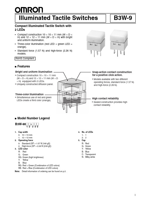
1B3W-9Illuminated Tactile SwitchesCompact Illuminated Tactile Switch with 2 LEDs•Compact construction 10 × 10 × 11 mm (W × D ×H) and 12 × 12 × 11 mm (W × D × H) with bright and uniform illumination.•Three-color illumination (red LED + green LED =orange).•Standard force (1.57 N) and high-force (2.26 N)models.■Features■Model Number Legend1.Cap width 0:10 × 10 mm 1:12 × 12 mm2.Operating force0:Standard (OF = 1.57 N {160 gf})2:High-force (OF = 2.26 N {230 gf})3.LED colorR:Red G:GreenHG:Green (high brightness)Y:Y ellow B:BlueRG:Red + Green (Combination of LED colors)RB:Red + Blue (Combination of LED colors)4.No. of LEDs 1:12:25.CapR:Red G:Green Y:Y ellow B:BlueC:Transparent N:Milky whiteNote:Detail information of ordering can be found on p.2.RoHS Compliant11 mm × D■List of Models10 × 10-mm SwitchesStandard force High-force Force LED color No. ofLEDsCap color ModelStandard force(OF = 1.57 N)Blue1Blue B3W-9000-B1B1Transparent B3W-9000-B1C1Milky white B3W-9000-B1N2Blue B3W-9000-B2B2Transparent B3W-9000-B2C2Milky white B3W-9000-B2NGreen1Transparent B3W-9000-G1C1Green B3W-9000-G1G1Milky white B3W-9000-G1N2Transparent B3W-9000-G2C2Green B3W-9000-G2G2Milky white B3W-9000-G2NGreen(highbrightness)1Transparent B3W-9000-HG1C1Green B3W-9000-HG1G1Milky white B3W-9000-HG1N2Transparent B3W-9000-HG2C2Green B3W-9000-HG2G2Milky white B3W-9000-HG2NRed1Transparent B3W-9000-R1C1Milky white B3W-9000-R1N1Red B3W-9000-R1R2Transparent B3W-9000-R2C2Milky white B3W-9000-R2N2Red B3W-9000-R2RRed +Green2Transparent B3W-9000-RG2C2Milky white B3W-9000-RG2NRed + Highbrightgreen2Transparent B3W-9000-RHG2CRed + Blue2Transparent B3W-9000-RB2CYellow1Transparent B3W-9000-Y1C1Milky white B3W-9000-Y1N1Yellow B3W-9000-Y1Y2Transparent B3W-9000-Y2C2Milky white B3W-9000-Y2N2Yellow B3W-9000-Y2YForce LED color No. ofLEDsCap color ModelHigh-force(OF = 2.26 N)Blue1Blue B3W-9002-B1B1Transparent B3W-9002-B1C1Milky white B3W-9002-B1N2Blue B3W-9002-B2B2Transparent B3W-9002-B2C2Milky white B3W-9002-B2NGreen1Transparent B3W-9002-G1C1Green B3W-9002-G1G1Milky white B3W-9002-G1N2Transparent B3W-9002-G2C2Green B3W-9002-G2G2Milky white B3W-9002-G2NGreen(highbrightness)1Transparent B3W-9002-HG1C1Green B3W-9002-HG1G1Milky white B3W-9002-HG1N2Transparent B3W-9002-HG2C2Green B3W-9002-HG2G2Milky white B3W-9002-HG2NRed1Transparent B3W-9002-R1C1Milky white B3W-9002-R1N1Red B3W-9002-R1R2Transparent B3W-9002-R2C2Milky white B3W-9002-R2N2Red B3W-9002-R2RRed +Green2Transparent B3W-9002-RG2C2Milky white B3W-9002-RG2NRed + Highbrightgreen2Transparent B3W-9002-RHG2CRed + Blue2Transparent B3W-9002-RB2CYellow1Transparent B3W-9002-Y1C1Milky white B3W-9002-Y1N1Yellow B3W-9002-Y1Y2Transparent B3W-9002-Y2C2Milky white B3W-9002-Y2N2Yellow B3W-9002-Y2Y2312 × 12-mm SwitchesStandard forceHigh-force■Ratings/Characteristics (Same for Both Standard and High-force Switches)■Operating CharacteristicsForce LED color No. of LEDs Cap color Model Standard force(OF = 1.57 N)Blue (high brightness)1Blue B3W-9010-B1B 1Milky white B3W-9010-B1N 2Blue B3W-9010-B2B 2Milky white B3W-9010-B2N Green1Green B3W-9010-G1G 1Milky white B3W-9010-G1N 2Green B3W-9010-G2G 2Milky white B3W-9010-G2N Green (highbrightness)1Green B3W-9010-HG1G 1Milky white B3W-9010-HG1N 2Green B3W-9010-HG2G 2Milky white B3W-9010-HG2N Red1Red B3W-9010-R1R 1Milky white B3W-9010-R1N 2Red B3W-9010-R2R 2Milky white B3W-9010-R2N Red + Green 2Milky white B3W-9010-RG2N Red + High bright green 2Milky whiteB3W-9010-RHG2NRed + Blue 2Milky white B3W-9010-RB2N Yellow1Yellow B3W-9010-Y1Y 1Milky white B3W-9010-Y1N 2Yellow B3W-9010-Y2Y 2Milky whiteB3W-9010-Y2NForceLED colorNo. of LEDs Cap color Model High-force (OF = 2.26 N)Blue 1Blue B3W-9012-B1B 1Milky white B3W-9012-B1N 2Blue B3W-9012-B2B 2Milky white B3W-9012-B2N Green 1Green B3W-9012-G1G 1Milky white B3W-9012-G1N 2Green B3W-9012-G2G 2Milky white B3W-9012-G2N Green (high bright-ness)1Green B3W-9012-HG1G 1Milky white B3W-9012-HG1N 2Green B3W-9012-HG2G 2Milky white B3W-9012-HG2N Red1Red B3W-9012-R1R 1Milky white B3W-9012-R1N 2Red B3W-9012-R2R 2Milky white B3W-9012-R2N Red + Green2Milky white B3W-9012-RG2N Red + High bright green 2Milky whiteB3W-9012-RHG2NRed + Blue2Milky white B3W-9012-RB2N Yellow1Yellow B3W-9012-Y1Y 1Milky white B3W-9012-Y1N 2Yellow B3W-9012-Y2Y 2Milky whiteB3W-9012-Y2NRatings1 to 50 mA, 5 to 24 VDC (resistive load)Ambient operating temperature −25°C to +70°C at 60% max. humidity (with no icing or condensation)Ambient operating humidity 35% to 85% (at +5 to +35°C)Contact form SPST-NOContact resistance 100 m Ω max. (initial value) (rated: 1 mA, 5 VDC)Insulation resistance 100 M Ω min. (at 250 VDC)Dielectric strength 500 VAC, 50/60 Hz for 1 min Bounce time 5 ms max.Vibration resistance Malfunction: 10 to 55 Hz, 1.5 mm double amplitude Shock resistance Destruction: 1,000 m/s 2 {approx. 100 G} max.Malfunction: 100 m/s 2 {approx. 10 G} max.DurabilitySwitch section1.57 N (standard force):1,000,000 operations min.2.26 N (high-force):300,000 operations min.ItemStandard-force Switches (B3W-90@0)High-force Switches(B3W-90@2)Operating force (OF) 1.57 N {160 gf} max. 2.26 N {230 gf} max.Releasing force (RF)0.2 N {20 gf} min.0.49 N {50 gf} min.Pretravel (PT)0.25+0.2/−0.1 mm4■LED Specifications(Ambient temperature Ta = 25°C)Note:For Switches with two LEDs, red and green, the recommended operating current is 12 mA for the red and 20 mA for the green LED for application with three-color illumination.■LEDs●Forward current reduction curve●Forward current and forward voltage curvesNote:1.Make sure that the polarity of the LEDs is correct. The polarity is not indicated on the Switch, but the positive pole is located on the back surface of the Switch on the side with the OMRON mark.2.Connect limiting resistors to the LEDs. The Switch does not have built-in limiting resistors, so satisfy the LED characteristics by obtaining the limiting resistance according to the following formula based on the voltage to be used.LED colorRedGreenGreen (high brightness)YellowBlueMaximum operating current I FM 27 mA 27 mA 27 mA 45 mA 27 mA Recommended operating current I F 20 mA 20 mA 10 mA 20 mA 10 mA Forward voltage (standard value) V F 1.8 V 2.1 V 3.7 V 2.4 V 3.7 V Maximum reverse voltage V R 5 V5 V5 V5 V5 VAmbient operating temperature−25°C to 70°C■Dimensions(Unit: mm)1 LED TypesB3W-900@-@1@B3W-901@-@1@2 LED TypesB3W-900@-@2@B3W-901@-@2@Note:Unless otherwise specified, a tolerance of ±0.4 mm applies to all dimensions. No terminal numbers are indicated on the Switches.56■AccessoriesB3W-9@@-F @Text Combination FilmsText Combination Films for B3W-9 Illuminated Tactile Switches•Display two different labels in combination with a 2-LED B3W-9 Switch. •Color combinations: Red/Green or Red/Blue■Model Number Legend1.ColorR:Red 2.ColorB:Blue G:Green3.Color and text combinationF1:Red OFFBlue or green ONF2:Red (OFF)Blue or green (ON)F3:Red (C L OSE)Blue or green (OPEN)F4:RedBlue or green F5:RedBlue or green Note:1.Five text combinations are available.2.Films can also be customized with other text for 50sheets (1,250 films) per lot. Delivery time is approxi-mately five weeks. (Ask your OMRON representative for details.)■Recommended B3W-9 Switches■Minimum Order25 films/sheetB3W-9 Films are sold in units of 25 films. Orders must be made in multiples of 25 (the quantity per sheet).Note:Text Combination Films are sold without the Switches. Or-der one of the above models of B3W-9 Illuminated Tactile Switches separately.Operating force2-LED SwitchesRed/BlueRed/Bright green Standard-force Switches B3W-9000-RB2C B3W-9000-RHG2C High-force Switches B3W-9002-RB2CB3W-9002-RHG2C■Safety PrecautionsNote:Refer to Safety Precautions in Tactile Switches (Cat. No. X037) for details on general safety precautions.■Precautions for Correct UseElectrical StandardsUse the Switch within the rated voltage and current ranges, other-wise the Switch may have a shortened life expectancy, radiate heat, or burn out. This particularly applies to the instantaneous voltages and currents when switching.Soldering1. Soldering Precautions•Before any kind of soldering, test to confirm that soldering can be performed properly. Otherwise the Switch may be deformed by the soldering heat depending on the type of PCB, pattern, or lands of the PCB.•Do not solder the Switch more than twice, including rectification soldering. Wait for at least five minutes between the first and sec-ond soldering to allow the temperature to return to normal. Con-tinuous soldering may cause the casing to melt or deteriorate the Switch characteristics.2. Automatic Soldering Baths (Wave Soldering)•Soldering temperature: 260°C max.•Soldering time: 5 s max. for a 1.6-mm thick single-side PCB •Preheating temperature: 100°C max. (ambient temperature)•Preheating time: Within 60 s•PrecautionsMake sure that no flux will rise above the level of the PCB. Also make sure that flux is not applied to the switch terminals or to the mounting surface of the PCB.If flux overflows onto the mounting surface of the PCB, it may en-ter the Switch and cause a malfunction.3. Manual Soldering•Soldering temperature: 350°C max. at the tip of the soldering iron •Soldering time: 3 s max. for a 1.6-mm thick, single-side PCB •Precautions:Before soldering the Switch on a PCB, make sure that there is no unnecessary space between theSwitch and the PCB.WashingStandard Switches are not sealed, and cannot be washed. Doing so will cause the washing agent, together with flux or dust parti-cles on the PCB, to enter the Switch, resulting in malfunction. PCBsThe Switch is designed for a 1.6-mm thick, single-side PCB. Using PCBs with a different thickness or using double-sided, through-hole PCBs may result in loose mounting, improper inser-tion, or poor heat resistance in soldering. These effects will occur, depending on the type of holes and patterns of the PCB. There-fore, it is recommended that a verification test is conducted before use. Handling1. Usage EnvironmentBefore installing the Switch, make sure that the area of installa-tion is not subject to corrosive gases emitted from surrounding parts.Do not use in areas subject to high temperatures, high humidity, or toxic gases such as sulfuric gas (H2S, SO2), ammonia gas (NH3), nitric gas (HNO3), or chlorine gas (CI2). It can cause corro-sive damage to the contacts and result in malfunction.If there is silicon in the atmosphere, it may stop the contacts from functioning properly.If silicon products, such as silicon oil, silicon filler, or silicon wires, are used in the surrounding area, install a contact protection cir-cuit to prevent arching or remove the silicon source.The following situations may cause water to enter inside the Switch, resulting in a malfunction due to contact failure or corro-sion.•Using the Switch in an outdoor environment where it is exposed to water drops for an extended period of time.•Using the Switch in an underwater setting where it is subject to strong water pressure.Do not use Switches that have been dropped. The mating section or other internal parts may be damaged, resulting in malfunction. OperationDo not repeatedly operate the Switch with excessive force. Apply-ing excessive pressure or applying additional force after the plunger has stopped may deform the disk spring of the Switch, resulting in malfunction.Be sure to set up the Switch so that the plunger will operate in a straight vertical line.If the plunger is pressed of-center or from an angle it may cause deformation or damage to some parts. This may result in deterio-ration of durability or malfunction.Dust ProtectionDo not install or use Switches in dust-prone environments. If a Switch must be used in this kind of environment, use a protective sheet or take other measures to protect it against dust.Note:Switches with high-brightness green (HG) or blue (B) LEDs are susceptible to static electricity. Be careful whenhandling a Switch with these LEDs as it may cause theSwitch to breakdown.7Removing the Cap1.Hold the cap at the side away from the mating section. Pullstraight up.2.Do not remove the cap while the Switch is mounted. Doingso will apply force to the soldered section and LEDs, result-ing in malfunction.Placing the Cap on the SwitchHold the Cap at the side away from the mating section. Push straight down until the mating section meets.Removing the CapThe Cap can be removed up to two times. Excessively removing the Cap will cause the mating section to become weak, resulting the operating section not mating completely or the Cap may fall off.Film DimensionsDimensions of the film are shown below. The thickness is 0.2 mm.Storage PrecautionsStorage EnvironmentT o prevent degradation, such as discoloration, of the terminals during storage, do not store the Switch in locations that are sub-ject to the following conditions.1. High temperature or humidity2. Corrosive gases3. Direct sunlightStorage conditionStore the Switches in the packaging box.After the packaging box is opened, use the contents as quickly as possible. When storing leftover parts, make sure that appropriate measures are taken against humidity and corrosive gases. Agreement of Product UseComply with the usage, storage, and disposal conditions speci-fied by OMRON as outlined in the precautions in the product datasheet and specifications.Correct IncorrectCorrectIncorrect。
OMRON 继电器使用事项
၄шၥଉ
後-1
開關之共通注意事項
●各產品別注意事項請參閱各產品之「正確使用須知」。
ᜰϞӓ ݧཎٱ
ႫᏢϞӓ ݧཎٱ
ĩႱۡĪୄࠢ Ϟᇳ݂
安全上的要點
•將開關做為緊急停止回路或攸關人身安全之安全回路使用時 , 必須選擇直接開路動作認定型 , 並使用具備直接開路動作機構 的NC接點端 , 然後設定為可利用正向模式進行動作 。 另外 , 為安全考量開關必須使用不易取下的螺絲或類似的方式 加以安裝 。 同時 , 請加上防護套或警告標示 。
၄шၥଉ
●使用微小負載機型時
若將一般負載用開關用於微小負載回路的開閉時,將有可能導致接
觸不良,請參考右圖,並在使用區域的範圍內使用開關。另外,即
使在右圖的區域內使用微小負載型開關,若在開閉時發生突波電流
等負載的話,接點耗損將會變大並造成耐用性不佳。因此請視需要
插入接點保護回路,最小適用負載為N基準參考值。這表示了信賴
前述接著劑或固定劑侵入開關內部時 , 將有可能發生動作不良 或接觸不良等情形 , 因此請特別注意 , 另外 , 有可能因為所 使用的接著劑或固定劑的種類而造成有害氣體發生或產生不良 的影響 , 因此請在充分確認後再加以選用 。 •請勿讓開關掉落或將內部拆解 , 否則不但將無法完全發揮出產 品特性 , 還有可能會導致產品破損或燒毀 。 •若該機種可以變更頭端的方向 , 並改變其頭端的方向時 , 請勿 讓異物附著在上面以確保其黏著性 , 另外 , 請依各機種正確的 鎖緊扭力將頭端的安裝螺絲鎖上 。 •為防止異物 、 油或水的入侵 , 請正確進行導線管處理 , 尤其 必須配合使用環境或纜線直徑選擇導線管以正確地安裝 , 並依 照適當的鎖緊扭力進行處理 。 •若開關保持在強行塞入的狀態 , 傳動軸上將會被施加震動或撞 擊力而導致局部磨損 , 並造成傳動軸的動作不良 , 因此請勿以 前述之方式來使用開關 。
OMRON使用说明书

目录1、概述 (1)2、测量原理 (1)3、技术参数 (1)4、选型指南 (2)5、安装方法和步骤 (4)6、信号线连接 (11)7、传感器调试 (11)8、故障排除 (11)9、智能流量积算仪 (12)10、无线远程流量监测系统 (14)11、后备电源 (14)12、壁挂式仪表箱 (14)13、型号编制说明 (16)14、涡街流量计操作指南 (17)11. 概述应力式涡街流量计是速度式流量计的一种,它以卡门涡街理论为基础,采用压电晶体检测流体通过管道内三角柱时所产生的旋涡频率,从而测量出流体的流量。
涡街流量计广泛应用于石油、化工、轻工、动力供热等行业。
涡街流量计具有以下特点:测量精度高,量程宽;测量介质广泛,可测量液体、气体和蒸汽;工作温度高,介质温度可达350℃;无运动部件,无磨损,可靠性高;表体采用不锈钢材料,耐腐蚀。
2. 测量原理当管道中流体介质通过旋涡发生体(三角柱)时,由于局部流速加速而产生旋涡现象(如图一),此旋涡分成两列交替地出现,这种旋涡列被称为卡门涡街。
卡门涡街的释放频率与三角柱宽度尺寸和流体的流动速度有关,而与介质的温度、压力等特性参数无关。
可用下式表示:f=S t V/d (1)式中:f—卡门涡街的释放频率S t—斯特罗哈尔(Strouhal)数V—介质流速d—三角柱的宽度斯特罗哈尔数是涡街流量计的重要参数,它只与介质的雷诺数Re有关。
只要管道内介质的雷诺数保持在2×10⁴至7×10⁶范围内,斯特罗哈尔数St便保持为一个常数,这样,便可通过测量旋涡频率信号检测出流体介质的流速,再通过介质的流速计算出介质的流量。
3. 技术参数◆公称口径:DN15、DN20、DN25、DN32、DN40、DN50、DN65、DN80、DN100、DN125、DN150、DN200、DN250、DN300、DN350、DN400、DN450、DN500;◆适用范围:气体(空气、氧气、氮气、煤气、天燃气、化学气体等)、液体(水、高温水、油、食品液、化学液等)、蒸汽(饱和蒸汽、过热蒸汽);◆可测介质温度:-40℃~280℃,-40℃~350℃;◆公称压力:≤1.6MPa ≤2.5MPa ≤4Mpa;◆精度等级:液体0.5级、气体、蒸汽1.0级;◆流速范围:液体0.6-6 m/s,气体:5-60m/s,蒸汽:5-70m/s;◆测量范围:见表一、表二;◆输出信号:电压脉冲:低电平≤1V,高电平≥6V,脉冲宽0.4ms,负载电阻>150Ω;标准电流:4-20mA,转换精度±0.5%满度值,负载电阻24V-500Ω,现场液晶显示:瞬时流量5位显示(m3/h、kg/h、t/h),转换精度±0.1%;累积流量9位显示(m3、kg、t),转换精度±0.1%;2◆供电电源:电压脉冲输出时:+12VDC,4-20mA输出时:+24VDC;现场液晶显示:3.6V 5号1节锂电池供电,使用寿命大于2年;◆环境温度:电压脉冲输出:-30℃—+65℃;4-20mA输出:-10℃—+55℃;现场液晶显示:-25℃—+55℃;◆表体材料:不锈钢(其他材料协议供货)。