03 G000005 Px20 Operation Presentation of S1 0605
OMAP3530 WinCE 1.00.00.05 DVSDK 发行说明说明书
OMAP3530 WinCE Digital Video Software Development Kit (DVSDK)DVSDK WinCE 1.00.00.05Release Notes Dec 04, 2009Important Note: Users must install the OMAP3530 WINCE DVSDK in order to access certain documentation hyperlinks in this document.IntroductionThis is the first DVSDK WinCE 100 source release targeted for OMAP3530 EVM.The DVSDK WinCE 100 product release is supported on OMAP35x EVM platform. This DVSDK, coupled with WinCE board support package, gives developers the ability to evaluate the hardware and software capabilities of the OMAP35x EVM platform with WinCE 6.0 R2/R3. Developers will be able to evaluate the ARM WinCE programming environment and easily utilize the powerful hardware support of the OMAP3530 SoC for various audio, video, speech and image codecs.This document is divided into the following sections:•Features•Documentation•DVSDK Package Contents•Installation and Usage•Upgrade and Compatibility Information•Host Support•Dependencies•Device Support•Validation Information•Exceptions and Known Issues•Limitations•Special Notes•Technical Support and Product UpdatesFeaturesThis DVSDK release includes support for OMAP3530 and OMAP3525 with the following features and has been tested with WinCE Board Support Package (BSP) R6.12.03:•Support for OMAP35x ES3.1 Silicon version with 256MB LPDDR•Backward compatible with OMAP35x ES2.1 Silicon version with 128MB LPDDR.•XDM 1.0 Codecs from TI.Audio: AAC LC/HE DecoderImage: JPEG Encoder/DecoderSpeech: G.711 Encoder/DecoderVideo: H.264 BP Encoder/Decoder, MPEG4 SP Encoder/Decoder, MPEG2 Decoder•DirectShow Filters•H.264 video decode directshow filter•MPEG4 video decode directshow filter•MPEG2 video decode directshow filter•DVSDK Demos and apps:•DMAI apps for performing file based decode and encodeoperations.•WMP to exercise media playback.•Digital Video Test Bench is not supported with this release.•WinCE 6.0 R2/R3 supportedDocumentation•DVSDK WinCE 100 Getting Started Guide - Hardware and software overview, including how to run demos, install software, and build thedemos. Latest Getting Started Guide can be found online here •Codec Engine Release Notes•Framework Components Release Notes•OMAP3530 Codec Server Release Notes•DaVinci Multimedia Application Interface (DMAI) Release Notes•Direct Show Filters (dshow) Release Notes•DSP/BIOS LINK Release Notes•DSP/BIOS Utilities Release Notes•EDMA3 Low Level Driver Release Notes•WinCE Utils Release Notes•XDAIS Release NotesDVSDK Package ContentsThe DVSDK contains the following components:biosutils_1_02_02 BIOS Utilitieswinceutils_1_00_02 Contiguous memory allocator for WinCEcodec_engine_2_24_01 The Codec Engine provides a framework for creating and interacting with multimedia codecsdmai_1_24_00_07 DaVinci Multimedia Application Interfacedshow_1_00_00_07 TI Directshow multimedia filters. dsplink_1_64 Foundation software for the inter-processorcommunication across the GPP-DSP boundary.framework_components_2_24_01 Framework Components is a collection offramework-independent utility libraries which othersoftware frameworks can build upon.cs1omap3530_1_00_01 Codec Server for decoding and encoding video,audio, speech and image.local_power_manager_1_24_01 Local Power Manager for DSP edma3_lld_01_06_00_01 EDMA3 Low Level Driver containing Resource Manager and Driverxdais_6_24_01_06xDAIS product contains the DSP AlgorithmInterface Standard specification and relateddocumentation and examples. A detailed DVSDK WinCE software manifest can be found hereThe DVSDK depends on the following tools/components:The DVSDK release is shipped with prebuilt components and these tools (exceptXDCTOOLS) are needed only for recompiling the individual components.XDCTOOLS is needed for DVSDK binary installation as well.Important Note: install XDCTOOLS and TI CodeGen tools in directories thatdon’t have any spaces in their path name (default installation path for thesetools may have spaces). Some of the DVSDK component builds fail if thereare spaces in the installation path of these tools.Installation and UsagePlease follow the Getting Started Guide for detailed installation and usageinstructions.Upgrade and Compatibility InformationThe OMAP3530 DVSDK release is independently installable. No upgradeinstructions are available with this release.bSquare WinCE 6.0 BSP Release 6.12.03 or later BSP for WinCE 6.0 R2/R3. bios_5_33_05Stand-alone DSP/BIOS. xdctools_3_10_05_61TI XDC tool. cg6x_6_1_9 TI C6x CodeGen tools.ActivePerl5.8 Active PerlHost SupportThis release supports installation and development on Windows XP workstations.DependenciesThe only known dependencies are listed here.Device SupportThis release supports the Texas Instruments OMAP3530 and OMAP3525 SoC. The verification was done on the OMAP35x Evaluation Module (TMDXEVM3503 and TMDSEVM3530)Validation InformationA sanity test of the DVSDK WinCE 100 build 1_00_00_05 was performed before release to the system test team. The sanity test covered the following tests. The validation was done on OMAP35x EVM.•Play AVI files with MPEG2, MPEG4 and H264 video decoder and MP3 audio decoder using Windows Media Player. Some of the test clips usedfor testing and benchmarking can be found here. http://software-/dsps/dsps_public_sw/sdo_sb/targetcontent/media/wince/index_FDS.html•Run DMAI demonstration applications as described in Getting Started Guide.In addition this release has gone through a complete QA cycle.Exceptions and Known Issues•MP3 playback can only be done on the ARM. This results in higher ARM-side CPU load.•Only AVI containers are supported.•AV synchronization is sometimes off for H.264 video clips at D1 resolution when the bitrate is high (e.g. >= 2Mbps) on Omap3530 ES2.1 siliconreading the media files from SD card. Performance can be improved byusing ES 3.1 silicon with multiple block reads enabled for the SDIO driver.•WMP cannot be run at the same time as DMAI applications, due to lack of an arbitrator of DSPLINK resources.•When performing jpeg image encode using DMAI application of an image with dimension (height or width) that is not a multiple of 16, leads todistorted output. This is a JPEG encoder known limitation.•When performing jpeg image encode using DMAI application, it was observed that using qfactor above 96 leads to misalignment in outputimage.•When performing AAC audio decode using DMAI application, high tone heard in decoded file after an aac decode operation.•When performing AAC audio decode using DMAI application, Mono files are decoded as dualmono during aac decode operations.•DMAI application does not support 411p and 422i as possible chroma formats•The default CMEM configuration allows JPEG encode and decode of images with resolutions upto 1280x720 (1MPixel) with YUV444, YUV422,YUV420 formats. Images of higher resolution can be encoded/decodedwith appropriate increase in CMEM buffer configuration within limits ofavailable memory•Rotation may not work for Video codecs that are part of WinCE 6.0 running on ARM (e.g, MPEG1 video, WMV video). These codecs do not handle the stride information properly. Please contact Microsoft for further details.•SDOCM00057731: MPEG2 Decoder: Flicker is observed at top of the display while decoding Mpeg2 streams of resolution 352x240 with videodecode•SDOCM00062310: MPEG2 Decoder: Generated yuv resolution is not same as the input stream resolution for some MP streams•SDOCM00060533: MPEG2 Decoder: Unable to decode certain clips @ QCIF resolutionFor latest list of known issues, please click on issues list. If this is your first time accessing this database please create an account hereDefects Fixed in DVSDK WinCE 1.00.00.05•Updated direct show filters enable Video Rotation using VRFB for Video codecs running on the DSP (H.264 decode, MPEG2 decode, MPEG4decode).•Optimization in Multimedia framework, higher DSP clock speed as well as adjustment in display driver buffer settings improves multimediaperformance. H.264 video clips at D1 resolution with bitrates of upto2Mbps can be played without any AV sync issue on ES2.1 silicon withmedia files on SD card. MPEG2 and MPEG4 video clips at D1 resolutionwith bitrates upto 4Mbps can be played without AV sync issues.Performance is further improved by using ES 3.1 silicon with multiple block reads enabled for the SDIO driver.Defects Fixed in DVSDK WinCE 1.00.00.04•CERuntime_exit() API is called by TI multimedia filter when closing Windows Media Player. This should free up unused resources.•Benchmarking (--benchmark option) is now supported in DMAI applications •WMP hangs due to exception in timm.dll when unsupported input file is selectedDefects Fixed in DVSDK WinCE 1.00.00.03•Reducing the window size of the Windows Media Player to a size smaller than the frame size may result in corrupted output.•Video display is corrupted when part of the display window lies outside the LCD display.•Directshow filters do not meet real-time and display is corrupted when video renderer operates in GDI mode (ie. when Windows Media Player ishidden by another window). This is because GDI mode requires YUV toRGB conversion of the DSP codec output frames.•DMAI Video Encode - for both H.264 and MPEG4 files, error pertaining to contiguous buffer causes failure•DMAI Image Encode - CMEM configurations to be provided for 1920x1280 and above resolutionsLimitationsSpecial Notes•In order to experience the demos and apps that comes with DVSDK WinCE 100, please refer to the Getting Started Guide.Technical Support and Product UpdatesPlease register your EVM serial number as instructed on the printed Read Me 1st Card in order to download the updated software release as soon as it becomes available.•For questions and support on the DVSDK WinCE 100, please visit .•Please be sure to read the Digital Video Software Development Kit (DVSDK) release notes, printed documentation and Getting Started Guide for general information.• A developer wiki site is available at/index.php?title=Main_Page. For information onOMAP35x, search for OMAP35x in the google toolbar embedded in thepage. User contributions are encouraged.。
CCD冲孔机控制计划

1
品质项目 QC
6±1kg/cm2
干净无异物 clean
干净无异物 clean
干净整洁 neat
安全液位之间 between safety level
R值:≤25.4um R value:≤25.4um
气压表 meter
目视 visual
目视 visual
目视 visual
目视 visual
二次元 secondary yuan
1次/月 once/month
BMJS-SOP2-AOI-07-01
生产 PDN
Reaction Plan (应变计划)
重新更换合格的冲针 new change correct
tool
更换新冲针 change new tool
1
CCD 冲孔 CCD Punching
CCD 冲孔机 Punching machine
品质管控
2
quality
control
3
机台气压 air pressure
4
吸嘴清洁 suck clean freq.
5
导轨清洁 guide clean
6
台面清洁 table clean
液压油箱油量
7
hydraulic tank fuel
quantity
8
重复精度 precision accurate
Part No. / Latest Change Level: (板号/最新更改水平)
Supplier Code: (供应商代号)
Control Plan 控制计划
Date (Orig.) (初始日期)
王氏港建 ATP-1000
Core Team: (核心人员)
Sophos APX 320X 操作指南说明书
Operating Instructions APX 320XForewardWe are pleased to welcome you as a new Sophos APX Series customer.Sophos APX Series access points are high performance wireless products using the latest 802.11ac Wave 2 technology for a best-in-class user experience. The APX Series models can be easily managed in Sophos Central, our cloud-based security management platform. All you need to do is set up a Sophos Central account and plug in the device anywhere in your network. The access point will find the cloud-based controller automatically and become operable within seconds.These operating instructions will help you set up your Sophos Central account, install and configure your Sophos APX Series access point and also provide detailed technical specifications. In addition, please also see the following documents that contain useful information on safety, regulatory compliance, and configuration options:ÌSophos APX Series Safety Instructions and Regulatory InformationÌSophos APX 320X Quick Start GuideThe instructions must be read carefully prior to using the device and should be kept in a safe place. You can download all user manuals and additional documentation from the Sophos Knowledgebase under /en-us/support/knowledgebase.aspx or from /get-started-ap.Security symbolsThe following symbol and its meaning appears in the Quick Start Guide, Safety Instructions and in these Operating Instructions.Caution and Important Note. If these notes are not correctly observed:ÌThis is dangerous to life and the environmentÌThe access point may be damagedÌThe functions of the access point will be no longer guaranteedÌSophos shall not be liable for damages arising from afailure to comply with the Safety InstructionsDesigned useThe access point must be installed pursuant to the current installation notes. Otherwise failure-free and safe operation cannot be guaranteed. The EU declaration of conformity is available upon request from the following address:Sophos Technology GmbHGustav-Stresemann-Ring 165189 WiesbadenGermanyOperating elements and connections N type connector for 2.4/5 GHz antenna (Radio 1)N type connector for 2.4/5 GHz antenna(Radio 0)N type connector for 2.4/5 GHz antenna (Radio 1)N type connector for 2.4/5 GHz antenna(Radio 0)Forge posts for mounting plate connection Gore vent LED RJ45 connector/Reset button Grounding wireconnectorComponent descriptionsLEDs* Your AP should recover from this state after a maximum of 5 minutes.Connection and configurationYour access point can be managed by a wireless controller located in Sophos Central. The initial connection of your access point to your network and the wireless controller is described in the APX Quick Start Guide which was shipped with your device or is available under /get-started-ap.For the access point to communicate with Sophos Central servers the following ports will need to be open on your firewall:Ì443 (HTTPS)Ì80 (HTTP)Ì123 (NTP)After successful connection you can start your initial configuration.Setting up your access point in Sophos CentralYou will need a Sophos Central account to manage your access points from Sophos Central. Please go to https:// to sign in under your account or create a new account.After signing in select Wireless from the popup screen or click on Wireless in the left navigation to get started.Follow the Onboarding Wizard to register your access point.For more information, please see the Sophos Central Admin Help.Setting up your access point in XG FirewallPlease note: APX 320X is not supported on XG or XGS Firewalls.Reboot and resetYour access point can be rebooted with the installed configuration or reset to the factory default configuration depending on how long you press and hold the reset button. Reboot with current image and configuration1. Press reset button.2. Release reset button.3. AP reboots (LED will go off, then will turn to solid green).Reboot with current image and clear configuration1. Press and hold reset button.2. AP reboots (LED will go off and then switch to green briefly).3. LED will turn solid red for 5 sec. You can still cancel the configuration clearanceprocess by releasing the reset button before the LED starts blinking.4. LED will blink red (configuration will be cleared).5. Release reset button.6. AP reboots with factory default settings.Technical specifications* Not available in the countries listed here: https:///support/s/article/KB-000039850 ** For the countries listed here: https:///support/s/article/KB-000039850Radiation patterns2.4 GHz BandH-plane V-plane—2400 (MHz) —2450 (MHz) —2500 (MHz)5 GHz BandH-plane V-plane—4900 (MHz) —5150 (MHz) —5350 (MHz)—5475 (MHz)—5725 (MHz)—5875 (MHz)Optional Sector / Directional AntennasTechnical specifications120° Sector AntennaFrequency range2400~2500 MHz5150~5850 MHzPort V-pol. / H-pol.V-pol. / H-pol.Antenna Gain10.6~10.8 dBi) / 10.0~11.4 dBi 12.5~13.1 dBi / 11.6~12.9 dBi HPBW / Horizontal76~77 deg / 63~66 deg40~61 deg / 52~76 deg HPBW / Vertical24~25 deg / 26~28 deg11~13 deg / 11~13 deg Isolation20 dBImpedance50 OhmsConnector N JackDimensions320 x 200 x 20.5 mm (12.6 x 7.87 x 0.81 inches)(Height x Width x Depth)30° Directional AntennaFrequency range2400~2500 MHz5150~5850 MHzPort V-pol. / H-pol.V-pol. / H-pol.Antenna Gain11.6~11.8 dBi) / 11.6~12.0 dBi 10.6~11.0 dBi / 10.4~11.5 dBi HPBW / Horizontal36~37 deg / 35~36 deg33~35 deg / 26~36 deg HPBW / Vertical34~35 deg / 36~38 deg32~39 deg / 30~41 deg Isolation20 dBImpedance50 OhmsConnector N JackDimensions320 x 200 x 20.5 mm (12.6 x 7.87 x 0.81 inches)(Height x Width x Depth)Radiation patterns Sector Antenna – Horizontal Polarization 2.4 GHz BandH-plane V-plane—2400 (MHz) —2450 (MHz) —2500 (MHz)5 GHz BandH-plane V-plane—4900 (MHz) —5150 (MHz) —5350 (MHz)—5475 (MHz)—5725 (MHz)—5875 (MHz)Radiation patterns Sector Antenna – Vertical Polarization 2.4 GHz BandH-plane V-plane—2400 (MHz) —2450 (MHz) —2500 (MHz)5 GHz BandH-plane V-plane—4900 (MHz) —5150 (MHz) —5350 (MHz)—5475 (MHz)—5725 (MHz)—5875 (MHz)H-plane V-plane—2400 (MHz) —2450 (MHz) —2500 (MHz)5 GHz BandH-plane V-plane—4900 (MHz) —5150 (MHz) —5350 (MHz)—5475 (MHz)—5725 (MHz)—5875 (MHz)H-plane V-plane—2400 (MHz) —2450 (MHz) —2500 (MHz)5 GHz BandH-plane V-plane—4900 (MHz) —5150 (MHz) —5350 (MHz)—5475 (MHz)—5725 (MHz)—5875 (MHz)Mounting instructionsThere are various mounting options available allowing you to hang your access point on the wall or mount it on a pole. Both options require the use of the mounting bracket which is shipped with your access point. The following sections provide detailed instructions on each of these options.Mounting bracketMounting holesVertical orientation mounting clamp slots Horizontal orientation mounting clamp slotsMountingattachment slotsMount plateattachment screwWall mount1. Use the mounting bracket to mark the screw mounting positions on the wall.2. Attach the access point to the bracket by hanging the 4 forge postsinto the attachment slots of the bracket and pressing it down.3. Tighten the attachment screw to fix the access point to the bracket.1.3.Tighten the attachment screwPole mount1. Attach the two metal clamps to the back of the mounting bracket using thevertical or horizontal mounting slots (according to the desired orientation).2. Hold the bracket against the pole and tighten the metal clamps.3. Attach the access point to the bracket by hanging the 4 forge postsinto the attachment slots of the bracket and pressing it down.4. Tighten the attachment screw to fix the access point to the bracket1. 2.3. 4.Sector / Directional Antenna Mounting Instructions1. Attach the articulating mount to the back of the Sector /Directional antenna using four of the supplied M6 nuts.2. Fix the T-form bracket to the pole by using the two supplied stainless steel hoseclamps.Please note: The clamps can be used for poles of 35-80 mm (1.5-3 inches) diameter.3. Fix the articulating mount to the T-form bracket by using thesupplied M8x40 bolts, nut, spring washer and washer.4.Direct the antenna upward or downward (max. angle is 27°) and fix it into place.1.27°27°Use a No. 12 hexagonal wrench to lock the M8 nut.4.M8x40 ScrewBoltsT-form BracketWasherSpring WasherM8 Nut3.2.Connect the Sector / Directional Antenna to the Access Point Connect the antenna to your APX 320X access point by using the supplied cables. You can use your sector/directional antenna either in combination with the standard omni-directional antennas or with another sector/ directional antenna.Choose the appropriate connection for the scenario which best fits your use case - as shown in the table below.NOTE: If you use the sector/directional antenna with the APX 320X in some countries, the use of Radio-1 may not be possible. Regulatory restrictions in some countries prohibit the use of low band 5 GHz channels which do not support DFS in outdoor environments. Therefore, Radio-1 cannot be configured when used in the countries listed here: https:// /support/s/article/KB-000039850. In those countries, this model will function as a single radio device (2.4 OR 5 GHz), your antennas should be connected to Radio-0 only, and concurrent use of the sector/directional and omni-directional antennas is not possible.a. b. c.Configure Sector / Directional Antenna Software SettingsOnce the external antenna is connected, please select the corresponding antenna settings in your Sophos Central Wireless admin account. Once selected and the configuration synched, the AP reboots and the correct power values will be set. WARNING: Failure to configure the correct antenna settings may place the AP outsideof regulatory limits. The administrator is responsible for ensuring this configuration is correct.Operating Instructions APX 320X© Copyright 2020-22. Sophos Ltd. All rights reserved.United Kingdom and Worldwide Sales Tel: +44 (0)8447 671131Email: ****************North American SalesToll Free: 1-866-866-2802Email: ******************Australia and New Zealand Sales Tel: +61 2 9409 9100Email: ****************.au Asia SalesTel: +65 62244168Email: ********************。
柔性检查作用域套件-USB 产品说明书
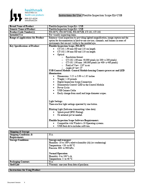
lInstructions for Use: Flexible Inspection Scope Kit-USB Brand Name of ProductFlexible Inspection Scope Kit - USB Generic Name of ProductFlexible Inspection Scope Kit - USB Product Code Number(s)FIS-007U, FIS-007USK, FIS-007UB, CT-101, CT-102Intended UseFor visually inspecting items.Range of Applications for ProductEnhance visual inspection by providing lighted magnification, image capture and the option for documentation in hard-to-see crevices, channels, and lumens in areas of instruments that are not visible to the unaided eye.Key Specifications of Product Flexible Inspection Scope- FIS-007U∙CT-101 1.90 mm OD and 110 cm length∙CT-102 1.06 mm OD and 110 cm length∙Opticalo Resolution format:o CT-102 1.06 mm: 40,000 pixels (or 200- x 200 pixels)o CT-101 1.90 mm: 160,000 pixels (or 400- x 400 pixels)o Field of View: 120° in airo Angle of view: 0°USB Control Module: Control Module housing Camera processor and LEDillumination:∙Dimensions: 5.25- x 3.90- x 1.85 inches∙Weight: 1.20 pounds ∙Digital Inspection Scope Connection∙Illumination Control- LED in the Control Module∙Power Cycle∙USB Camera Cable∙Easily change from small and large diameter scopes.Light Settings:There are four light settings operated by one button.Blinking Light (Indicates transmitting video data):∙Splash proof (IPX5 Rating)∙No external power needed.Flexible Inspection Scope Software Requirements:∙Compatible with Windows 10 Operating systems.∙USB flash drive includes software.Unpacking Flexible Inspection Scope:Carefully inspect for shipping damage. If there is any damage contact the shipping carrier and Heatlhmarkcustomer service 800-521-6224 immediately.USB Control Module: (Fig. 1).1.Digital Inspection Scope Connection 2.Illumination Control 3.Power Cycle B (Type C) on the right side of the boxFigure 1Flexible Inspection Scope™: (Fig. 2).∙CT-101 1.90 mm O.D. and 110 cm length ∙CT-102 1.06 mm O.D. and 110 cm lengthLarge1.90 mmSmall 1.06 mmFigure 2Flexible Inspection Scope™ Features3214Light/Illumination Settings: (Fig. 3).∙Five (5) light settingso Light on control indicats setting levelo Fifth setting is OFF∙Press light button to advance to next setting.∙Fifth setting turns the light OFF.Figure 3Power Cycle ButtonPress button to RESET camera (Fig. 4).Figure 41.Flexible Inspection Scope™ Plug (Fig. 5).Contains camera video connection as well as LED Light for illumination.1Figure 52.Flexible Working Length (Fig. 6).The portion of the Flexible Inspection Scope™ that is inserted into an item during visual inspection.The measuring scale markings on the Flexible Working Length are in centimeters (accuracy = ± 0.5 cm)2Figure 63.Distal Camera (Fig. 7).Distal portion of Flexible Inspection Scope™ that contains the camera lens3Figure 7SOFTWARE INSTALLATION:Note: This section is done only once when connecting the scope to the computer for the first time.∙System Requirements: MS Windows 10∙Install the Flexible Inspection Scope™ Software from the USB flash drive on a computer.Note: If you have any IT policies that may block this installation, please contact your IT team to give access to Healthmark scope viewer to install.1. Insert the USB Flash drive into your computer, and double click on the Healthmark Scope Viewer installer package to begin installation.2. The “Welcome to the Healthmark Scope Viewer Setup Wizard” screen pops up. Click on Next.3. Select the first tab Typical or setup type of your choice, click Next.4. Click Install and wait for installation to complete.5. Click Finish.STARTING SOFTWARE & CONNECTING SCOPE TO PC:(Fig 8).1.Open the Windows PC viewer software.2.Connect the Control Module to PC using USB Cable.3.Plug the Flexible Inspection Scope into the Control Module.4.In the viewer software, click Settings and Select USB Video Device, click on the desiredresolution, select the preferred Video Output Format, and then Click OK.5.Press the Power Cycle Button.Figure 86.Now you can start using the scope.Verifing OperationFollowing the steps listed below will ensure the proper use and performance of the Flexible Inspection Scope™. The Flexile Inspection Scope™ can be checked for normal operation by connecting it as described in the Startup section of this IFU.Normal operation includes:∙An image appearing on your computer monitor or HDMI Monitor.∙ A blinking light on Control Module near the Power Cycle button that indicates the image feed is transmitting.∙White light emitting from the distal end of the Digital Inspection Scope.∙An LED light on the control module top panel that indicates the light intensity of the device. Using SoftwareHealthmark Scope Viewer Software (Fig. 9).1.Capture button: Captures a Reference Image and saves it to the Reference Image folder.2.Main Image Window: Displays the image from the camera.3.Reference Image Window: Displays a reference image.4.Clear Button: Removes the image from the Reference image window.5.Open Reference Image button: Allows selection of a reference image from the Reference Imagefolder.6.Settings Button: Click to select the video camera and resolution settings.7.File Location Button: Click to change location where captured images are being saved.8.File Location Window: Shows the file path where captured images are being saved currently.9.Capture Image Button: Captures images and adds them to the File Location selected by the user(as shown in the File Location Window).10.Capture Video button: Click to record video. Click again to stop recording video.11.File Prefix: Type in text that you would like included in the file name of Captured Images.Figure 9Selecting Video Device or CameraFollow the directions below to select the video device or camera used to capture images using the Flexible Inspection Scope™ Viewer Software. (Fig. 10).1.Click Settings button in the lower left of the Scope Viewer software to display a list of videodevices or cameras being detected by your computer2.Select a device for capturing images using the Scope Viewera.The example below shows a webcam and USB Video Device in the Settings box. Select theUSB Video Device for the Flexible Inspection Scope™.b.You can also select your preferred Video Output Format from the dropdown box3.Click OK to view the selected Video Device.231Figure 10Capturing Still PicturesFollow the instructions for capturing still pictures from the Main Image Window.Select the Capture Image button. (Fig. 11).Figure 11Note: When an image is captured, “Image Captured” in red text will flash on the lower portion of the screen and a new file will appear in the Files Location.Capturing Video ImagesFollow the instructions below for capturing video from the Main Image Window.1.Select the Capture Video Button (Fig. 12).Figure 122.When the video is recording “Recording…” in red text will appear toward the bottom of thesoftware window.3.To stop recording, click Stop Capture. (Fig. 13).Figure 13Setting File PrefixFollowing the steps below allows you to create a file prefix that will appear after the underscore of image file names save to the File Location specified by the user.1.Click in the field next to File Prefix.2.Enter the characters that you would like to be included in the file name. (Fig 14).Figure 14Setting Location for Saved FilesFollowing the steps below allows you to set the file location of saved images using the Scope Viewer software.1.Click the File Location button.2.Select the file location you want to save captured images. (Fig 15).Figure 15Displaying Reference ImageThere are two ways to display a still image in the Reference Image Window on the Scope Viewer software.1.To display an image currently being displayed in the Main Image Window, click the Capture button. Note: The images will be saved in a file folder titled Reference Images in the designated File Location that the user specified in the File Location field. (Fig. 16).Figure 162.To display a saved image in the Reference Image Window from your File Location:a.Click the Open Reference Image button (Fig. 16 above).b.Select the file you want to display (Fig. 17 below).c.Click the OK Button, to display the image in the Reference Image Window. (Fig. 17).Figure 17Switching to a Different Flexible Inspection Scope™ on the Control Module:1.Press the Power button on the Control Module once.2.Disconnect the current Flexible Inspection Scope from the Control Module.3.Repeat the steps in the “STARTING SOFTWARE & CONNECTING SCOPE TO PC” procedure.Inserting Scope in ItemFigure 1Rotating Device to Avoid ObstacleFigure 2 Performing InspectionWipe down the Flexible Inspection Scope™ with a compatible wipe. Follow the manufacturer’s (Mfr.’s)Instructions for Use (IFU) for appropriate wipe usage. Click here to see the Chemical Compatibility Chart(PDF) for approved cleaning.The Flexible Inspection Scope™ is made of the same material as other common endoscopes. Any wipe,solution, or low temperature (≤ 60 °C [140 °F]) method intended for the reprocessing of endoscopes is likelycompatible with the Generation II Flexible Inspection Scope™ Catheters if used according to the productlabeling.Solutions Containing (Flexible Inspection Scope Only)Alcohol Ethoxylates Neutral or Near-Neutral pH DetergentsEnzymatic Cleaning Solutions Enzymatic DetergentsSodium Borated, Decahydrate Tetrapotassium PyrophosphateFlexible Inspection Scope™ has a fluid ingress protection rating of IPX7 (Waterproof) and can withstandimmersion in fluid up to one (1)-meter in depth for up to 30 minutes.Control Module USB has a fluid ingress protection rating of IPX5 (Water resistant) and can withstand asustained, low pressure water jet spray for up to three minutes.For Thorough Cleaning: CablesFollow the cleaning agent Mfr.’s IFU.1.Unplug and disconnect all components from the Control box prior to cleaning.2.Do not submerge or soak the cable for disinfection (cable is not waterproof).3.Wipe thoroughly with non-linting wipe moistened with facility approved neutral detergent. Use theappropriate brushes with detergent solution to remove any residues from areas that cannot bereached with the wipes.For Thorough Cleaning: Control Module1.Unplug and disconnect all components from the Control box prior to cleaning.2.Do not submerge or soak the cable for disinfection (Control Box is not waterproof).3.Wipe thoroughly with non-linting wipe moistened with facility approved neutral detergent. Use theappropriate brushes with detergent solution to remove any residues from areas that cannot bereached with the wipes.Note: Do NOT soak. Control Module and cables are not waterproof and should not be immersed.N/ACleaning –AutomatedDisinfection Control Module and CablesThese may be cleaned with alcohol based disinfectant wipes.Compatible agents (wipes and solutions) for disinfecting Flexible Inspection Scope™ and ControlModule:∙Hydrogen peroxide∙Isopropyl alcohol (IPA)∙Sodium hypochlorite (Bleach)∙Ortho-phenylphenol∙Quaternary ammonium.High-Level Disinfection (Flexible Inspection Scope™ Only)∙Select only disinfecting solutions listed in the compatible disinfecting methods.∙Follow all recommendations regarding health-hazards, dispensing, measuring, and storage from the Mfr. of cleaning and disinfecting agents.∙Soak the Flexible Inspection Scope™ in selected disinfecting solution per Mfr.’s IFU.∙Rinse the Flexible Inspection Scope™ with critical (sterile) water, again, following the disinfecting solutions Mfr.’s instructions.Reprocessing Chemical Compatibility Chart (PDF): Click here.。
北京发格自动化设备 错误排除说明书

错误排除参考手册(车床系统)Ref 0112-ing北京发格自动化设备有限公司目录编程错误 (3)准备功能和执行错误 (31)硬件错误 (47)PLC错误 (50)伺服错误 (51)表格数据错误 (56)TC工作模式下的错误 (58)编程错误0001 ‘Linea vacia’检测时间:在CNC上进行编辑或在执行通过DNC传输的程序时。
引起原因:引起这种错误的原因可能是:1. 当试图进入程序或执行一段空程序段或包含有标号(程序段号)时。
2. 在“模式重复固定循环(G66)”,“沿X轴的粗加工固定循环(G68)”或“沿Z轴的粗加工固定循环(G69)”中,当参数“S”(轮廓的开始)大于参数“E”(轮廓的结束)时。
解决方案:每种情况的解决方案为:1. CNC不能进入程序或执行空程序段。
要进入程序中的空程序段,在该程序段的开始使用符号《;》。
CNC将忽略该程序段的其余部分。
2. 参数“S”的数值(开始定义轮廓的程序段)必须小于参数“E”的数值(轮廓定义的结束的程序段)。
0002 ‘不合适的数据’检测时间:在CNC上进行编辑或在执行通过DNC传输的程序时。
引起原因:引起这种错误的原因可能是:1. 当切削条件(F,S,T或D)或M功能后编辑轴坐标时。
2. 当程序段跳转标志(条件段/1,/2或/3)不在程序段开始时。
3. 当用ISO代码格式编程时,编写的程序段号大于9999时。
4. 在用高级语言编程时,RPT指令的数值大于9999。
解决方案:每种情况的解决方案为:1. 记住编程的顺序。
2. 记住编程的顺序:-程序跳转(条件程序段段/1,/2或/3)。
-标号(N)。
-《G》功能。
-轴坐标(X,Y,Z…..)。
-加工条件(F,S,T,D)。
-《M》功能。
3. 更正程序段的语法错误。
程序段的标号应在0到9999之间。
4. 更正程序段的语法错误。
程序中的重复次数应在0到9999之间。
0003‘不合适的数据顺序’检测时间:在CNC上进行编辑或在执行通过DNC传输的程序时。
富士3500胶片打印机报错代码及解决办法
富士3500胶片打印机显示代码说明换胶片:1.屏幕若显示“pro”表示机器正在工作请勿移动片盒2.取出要需更换的片盒,此时显示屏提示“203”及蜂鸣声,因为片盒被取出,按“回车键”蜂鸣声消失3.装好胶片放回片盒常见错误代码:201:上盖板打开重新合上203:上片盒取出重新插上204:下片盒取出重新插上206:上片盒卡片(拔出片盒,取出片槽里的胶片)或打开上盖,抬起绿色热敏头,手动取出。
207:下片盒卡片(拔出片盒,取出片槽里的胶片),或打开后盖,手动取出209:上片盒没有胶片,请更换210:下片盒没有胶片,请更换218:关闭打印机重新启动219:关闭打印机重新启动220-230:相机卡片,请查看231:请拔插上片盒,若无法解决,更换上片盒芯片241:请拔插下片盒,若无法解决,更换下片盒芯片开机:打开左侧黑色总电源,按下机器显示屏旁“圆形”按钮开机关机:长按机器显示屏旁边“圆形”按钮5 秒钟,显示END,手松开,即将关机工作站任务发过去打印机不打印,需拔插上下片盒,重新插入胶片图像打出效果不好需要校准热敏头(上下片盒校准方法)1、上片盒胶片校准:(按相机显示屏旁边“菜单键”-0-1--按“回车键”-SL1-按“回车键”一U-1 会闪烁一会打印出一张校准片即可)2、下片盒胶片校准:(按相机显示屏旁边“菜单键”-0-1-按“回车键”-“菜单键”-SL2-按“回车键”一U-1会闪烁一会打印出一张校准片即可)相机维护、胶片图像若出现条状痕迹:1、相机滚轴有灰尘可以拿出来,用清水洗净,晾干,放回原位(打开相机上盖板,抬起绿色热敏头盖,取出黑色滚轴)2、或者是热敏头脏了,关闭电源,打开相机上盖板,抬起绿色热敏头盖,等热敏头冷却,请用酒精棉擦除热敏头上黑色区域灰尘,等待酒精挥发后,放回原位。
X20(c)BC0083数据手册说明书

X20(c)BC00831 General informationThe bus controller makes it possible to connect X2X Link I/O nodes to POWERLINK. It is also possible to operate the X2X Link cycle synchronously 1:1 or synchronous to POWERLINK using a prescaler.POWERLINK is a standard protocol for Fast Ethernet with hard real-time characteristics. The POWERLINK Stan-dardization Group (EPSG) ensures openness and continuous advancement. •POWERLINK•I/O configuration and Firmware update via the fieldbus•Integrated hub for efficient cabling2 Coated modulesCoated modules are X20 modules with a protective coating for the electronics component. This coating protects X20c modules from condensation and corrosive gases.The modules' electronics are fully compatible with the corresponding X20 modules.For simplification purposes, only images and module IDs of uncoated modules are used in this data sheet.The coating has been certified according to the following standards:•Condensation: BMW GS 95011-4, 2x 1 cycle•Corrosive gas: EN 60068-2-60, method 4, exposure 21 days2.1 Starting temperatureThe starting temperature describes the minimum permissible ambient temperature when the power is switched off at the time the coated module is switched on. This is permitted to be as low as -40°C. During operation, the conditions as specified in the technical data continue to apply.Information:It is important to absolutely ensure that there is no forced cooling by air currents in a closed control cabinet, for example using a fan or ventilation slots.3 Order dataTable 1: X20BC0083, X20cBC0083 - Order data 4 Technical dataTable 2: X20BC0083, X20cBC0083 - Technical dataTable 2: X20BC0083, X20cBC0083 - Technical data1)See Automation Help under "Communication / POWERLINK / General information / Hardware - CN" for more information.2)The minimum cycle time specifies the time up to which the bus cycle can be reduced without communication errors occurring.3)Spacing is based on the width of bus base X20BB80. In addition, power supply module X20PS9400 or X20PS9402 is always required for the bus controller.5 Operating and connection elements5.1 LED status indicators1)The Status/Error LED "S/E" is a green/red dual LED. LED status indicators - Blink times5.2 POWERLINK node numberThe node number for the POWERLINK node is set using the two number switches.5.3 Ethernet interfaceFor information about wiring X20 modules with an Ethernet interface, see section "Mechanical and electrical con-figuration - Wiring guidelines for X20 modules with Ethernet cables" of the X20 user's manual.Ethernet RXD 6 Dynamic node allocation (DNA)Most POWERLINK bus controllers have the ability to dynamically assign node numbers. This has the following advantages:•No setting of the node number switch •Easier installation•Reduced error sourcesFor information regarding configuration as well as an example, see Automation Help → Communication → POW-ERLINK → General information → Dynamic node allocation (DNA)Information:Interface IF1 must always be used as the input from the preceding node.7 SG3This module is not supported on SG3 target systems.8 SG4The module comes with preinstalled firmware. The firmware is also part of the Automation Runtime operating system for the PLC. With different versions, the Automation Runtime firmware is loaded onto the module.The latest firmware is made available automatically when updating Automation Runtime.。
浪潮存储DCS02和DCS03系统产品安装指导书
第1页/共47页Copyright and Confidentiality StatementAny information contained in this document, whether it is related to Inspur or its partners, including but not limited to functional description, policies, processes, decisions, employee information, agent and customer information, and all financial data, shall be kept in strict confidence.Copyright© Inspur Group Limited 2014文档信息文档修改记录版权及保密性声明本文档中包含的所有信息,无论涉及到浪潮还是其合作伙伴(包括但不限于功能描述、政策、流程、决定、雇员信息、代理及客户信息以及所有的财务信息),都必须绝对保密。
本文件中出现的任何文字叙述、文档格式、插图、照片、方法、过程等内容,除另有特别注明,版权均属浪潮信息所有,受到有关产权及版权法保护。
任何单位和个人未经浪潮信息的书面授权许可,不得复制或引用本文件的任何片断,无论通过电子形式或非电子形式。
浪潮集团版权所有© 2013目录1.产品介绍 (5)1.1.产品参数 (5)2.调试过程 (7)2.1.硬件安装 (7)2.1.1.硬盘安装 (7)2.1.2.连接扩展柜 (7)2.2.系统授权码申请及注册 (12)2.2.1.获取机器码 (12)2.2.2.授权码注册 (12)重要说明 (13)2.3.存储配置 (13)2.3.1.磁盘信息 (14)2.3.2.卷组管理 (16)2.3.3.逻辑卷管理 (17)3.映射主机 (19)3.1.FC-SAN (19)3.1.1.FC主机组管理 (19)3.1.2.增加FC主机 (20)3.2.IP-SAN (23)3.2.1.主机组信息 (23)3.2.2.新建主机组 (24)3.2.3.增加主机 (24)3.2.4.映射磁盘 (24)4.IP-SAN环境ISCSI启动器的安装与配置 (25)4.1.WINDOWS系统ISCSI启动器安装与配置 (25)4.2.Linux 上启动器的安装和使用 (31)5.多路径软件的安装 (33)5.1.Windows多路径功能 (33)5.1.1.Windows 2003 MPIO安装设置 (33)5.1.2.Windows 2008 MPIO 安装设置 (33)5.1.3.Linux多路径安装配置 (41)6.日常维护 (45)6.1.通过下图方式查看存储的网络配置 (45)6.2.AS500G\AS500E\AS520G通过下图方式存储的关机重启 (46)6.3.AS520E开关机 (46)6.4.AS500G\AS500E\AS520G\AS520E日志收集 (46)1.产品介绍1.1. 产品参数AS500G\AS500EAS520GAS520E对于520G起跳存储系统版本要求DCS02 1.2.8.1 对于520E起跳存储系统版本要求DCS03-2.0.0.22 两者采用不同的系统灌装镜像2.调试过程2.1. 硬件安装2.1.1.硬盘安装AS500G\AS500E\AS520GAS520E2.1.2.连接扩展柜AS500G/AS500E的扩展柜为AS500GJ或者AS500EJ扩展柜示意图如下,最大扩展3个JBOD,连接方式为树状结构:AS520G/.AS520GJ后视图AS520G默认只有一个磁盘通道最多接4个JBOD,以4个AS520GJ为例,连接方式为串行架构如下如果超过4个JBOD就需要再AS520G上增加一个双口的SAS卡,扩展柜连接规律1-2-3-1循环规律,以8个AS520GJ的连接方式如下AS520E\AS520EJ后视图AS520E配套的磁盘扩展柜AS520EJ,目前支持到3个2.2. 系统授权码申请及注册2.2.1.获取机器码通过控制器的IP地址登陆每个控制器,获取两个控制器的机器码2.2.2.授权码注册将两个控制器的系统机器码、购买的功能选择等信息发送给浪潮客户服务部为您产生产品授权码,并发送邮件或致电给您。
- 1、下载文档前请自行甄别文档内容的完整性,平台不提供额外的编辑、内容补充、找答案等附加服务。
- 2、"仅部分预览"的文档,不可在线预览部分如存在完整性等问题,可反馈申请退款(可完整预览的文档不适用该条件!)。
- 3、如文档侵犯您的权益,请联系客服反馈,我们会尽快为您处理(人工客服工作时间:9:00-18:30)。
36
可编程逻辑方案
可编程逻辑与整定菜单一体,可满足特殊要求
定值操作
Px20
光隔输入 与逻辑门
输出接点
保护元件
& &
& &
时间元件
控制
固有逻辑 用户可编程逻辑
指示灯
37
> Title of presentation - Date - References
37
MiCOM Px20
通信
38
> Title of presentation - Date - References
Px20
故障录波 故障报告 事件记录
远方CB遥控、信号复归
31
> Title of presentation - Date - References
31
定值操作
选择 “Device”,然后进入 “ Communication Setup”
选择合适的串口(例如 COM1)
Px20
报警的状态 元件的启动或跳闸 (包括故障报告) 定值的改变
事件记录的内容
14
> Title of presentation - Date - References
14
Px20保护
记录查看
从面板液晶读取
有新报告产生时,可直接按阅读键读取该报告。 历史记录不能通过液晶进行查看。
21 > Title of presentation - Date - References 21
故障录波操作
COMTRADE 格式浏览器 用户可以分析的功能:
Px20保护
模拟量和数字量的查看 打印 峰值和实时有效值的查看
22
> Title of presentation - Date - References
32
> Title of Байду номын сангаасresentation - Date - References
32
定值操作
选择 “Device”, 然后打开连接选择 “ Open Connection”
输入的地址必须和 COMMUNICATIONS中设置的一样
Px20
输入密码,默认“AAAA”
Re l a y A d d r e s s 25
后视图
接地端子
M4 螺母
9
> Title of presentation - Date - References
9
Order Px20的选型
MiCOM Px20
详细信息参考相应型号的选型表
保护种类
零序电流工作范围 固定为0 (用于选择交流额定电压) 特殊硬件要求(固定为0) 辅助电源 (Vx) (固定为0) 通信规约 (K-Bus etc.) 语言 (English / Russian) 安装方式 (Flush / Panel)
选型
P122B00M311
11
> Title of presentation - Date - References
11
Events 记录
Px20保护
记录操作
75个事件记录(保护元件启动.报警逻辑动作.输入输出 变位和装置上电等都会产生事件记录) 5个(3S)故障录波(可由保护元件和输入输出来触发录波 , 通常设置为保护跳闸触发录波,可以设置故障前时间 和录波总长).
面板 定值组选择
2组定值
1 2
可以通过 维护软件 修改
29
29
> Title of presentation - Date - References
定值操作
Px20
30
> Title of presentation - Date - References
30
定值操作
上传下载装置的定值
离线在线配置装置 提取
Memo 注意事项
Px20保护 FAQ常见问题&解决方案1
Px20的RS485通信口屏蔽双绞线的屏蔽地的多点接地。
从设计上不要把屏蔽地和装置的地接起来。
如何启动Trip LED?
“Trip” LED和出口“RL1”是和固定和“AUTOMAT.CTRL-TRIP
1
Px20
上盖板
6
液晶显示
跳闸指示
9
报警指示
10 5
查看报警/故障信息
装置退出运行
11 4
操作按键
电源指示
2
3
4个用户定义指示灯
7
8
下盖板封锁孔
下盖板
13
电池
8
> Title of presentation - Date - References
8
2 插接端子 4.8mm x 0.8mm
MiCOM P12x 馈线保护
测量查看
可以查看装置的实时有效值 刷新时间可以设置
Px20
装置的自检功能和报告都可以查看
27
> Title of presentation - Date - References
27
Setting 定值
定值组切换
定值操作
Px20
光隔输入 定值组选择 SCADA或 PLC 定值组选择
OP PARAMETER 运行参数 CONFIGURATION 配置 MEASURMENT 配置
可以通过 维护软件 查询
测量查看
Px20
IA 0000.00
25 > Title of presentation - Date - References 25
测量查看
Px20
单击此按钮
26 > Title of presentation - Date - References 26
通过维护软件MICOM S1获取
正确连通后,使用 EXTRACT 功能获取事件记录,保存。 打开保存的记录就可查看。 对于故障录波必须使用“Comtrade”浏览器打开录波文件
查看波形
15
> Title of presentation - Date - References
15
事件记录操作
产品范围
P920 P820
电压频率保护 断路器失灵保护
P520
联络线光纤差动保护
P220 P120
电动机保护 过流和接地保护
5
> Title of presentation - Date - References
5
装置外观
Px20
20TE机箱
30TE机箱
6
> Title of presentation - Date - References
事件记录操作
详细信息可以单击 “ + ”进行展开
Px20保护
18
> Title of presentation - Date - References
18
故障录波操作
Px20保护
19
> Title of presentation - Date - References
19
故障录波操作
可以存储5个故障录波 可以定义故障前时间和故障后事件 (最大3秒) 故障录波的触发可以选择 START (ON INST)或 TRIP (ON TRIP)
装置的地址显示在 COMMUNICATIONS 菜单中
33
> Title of presentation - Date - References
33
定值操作
必须选择正确的型号进行编辑 装置的型号和 软件版本必须知道 如果装置的型号为 例如 P123A00F341 软件版本为 V6 那么正确的选择应该为: 选择错误的软件版本会
38
Px20通信
总体特点
通信规约种类
Modbus RTU
IEC60870-5-103 DNP3.0
Courier
只有一个RS485的通信口 没有以太网和光纤通信口
39
> Title of presentation - Date - References
39
错误的接线
Px20通信
清除/复归新产生记录
16 > Title of presentation - Date - References
16
事件记录操作
打开连接后点击 “ Device ”,然后选择 “Extract” - “Events”
Px20保护
输入文件名后 “Save” 事件
然后事件会自动打开
17 > Title of presentation - Date - References 17
Px20保护
20
> Title of presentation - Date - References
20
故障录波操作
打开连接,单击 “Device”, 然后选择 “Extract” - “Disturbances”
Px20保护
选择好想要提取的故障录波后 “Save”
打开故障录波浏览器进行查看
6
MiCOM Px20
特点
双额定CT 1/5A输入
易于整定 和查询
可编程的 LEDs
强大的 记录功能
灵活的 通信方式
抽出式 便于更换
可编程的 开入和开出
MiCOM40-7 7 > Title of presentation - Date - References 7
Px20继电器面板
复位键