MB63HXXX中文资料
擴音器說明書说明书
Microphone
External Microphone Plug
External DC Power Supply Plug
Button Switch
Recording
Cyclic playing Function Switch
LED-Red
FRONT PANEL
123
456
789
0
REC PLAY
2. Twinkle Twinkle Little Star
27. Wedding March/Wagner
3. Little Bee
28. Wedding March /Mendelssohn
4. Jingle Bell
29. Canon
5. Silent Night
30. Romance De Amor
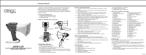
1.1 megaphone (including shoulder strap) 1.2 battery holder (batteries not included) 1.3 instruction manual 2. PARTS & FUNCTIONS (refer to illustration)
Belt
3.2 16-Second of recording time
3.3 Cyclic playing for all the melody selection & self-recording
3.4 Low distortion, and good performance
3.5 Uni-directional microphone is used to get maximum gain before feedback
程式性直流电压负载 Chroma 63200系列说明书

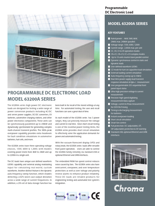
ProgrammableChroma's 63200 series of programmable electronicloads are designed for a wide variety of dc powerconversion products including; DC power sources,battery chargers, server power supplies, dc-dcconverters, batteries and many others. Thehigh power rating, parallel and synchronizationcapabilities, and the ability to provide up to 2.7times of rated power for short duty cycle loadingmake 63200 series especially well-suited for highpower applications such as switch-mode rectifiersand for discharging batteries packs and fuel cells.The 63200 series offers 12 different models withpower ranges from 2600 watts to 15600 watts,currents from 50A to 1000A and operatingvoltages from 0 to 1000V. By paralleling modulesvery large systems can be assembled existing93.6kW. Four operating modes provide differentload simulation methods designed for variousapplications. The CC/CR modes are designedto test constant voltage power supplies andconverters. CV mode simulates the battery fortesting battery chargers and current sources, andCP mode is ideal for battery testing by simulatingreal discharge profiles.The 63200 series can sink rated current downto 1VDC even under the highest specified risetime. This unique feature guarantees the bestloading performance for low voltage/high currentapplications. With it's unique external waveformsimulation and Master / Slave control capability,the 63200 series electronic loads allow users toparallel and synchronize more than one loadtogether using an internal or external loadingcontrol signal. This feature provides unlimited loadsimulation and increased power.The 63200 series also provides necessar ymeasurement func tions and shor t circuitsimulations that extend the test capability for themost demanding engineering and automated testapplications.With front LCD displays and rotary knob, the 63200loads offer versatile bench top operation. Users arealso able to control the loads remotely via GPIB orRS-232 interface or with a USB adapter. Complexwaveforms can also be created by driving theloads from an analog programming source (i.e.function generator).Chroma 63200 loads incorporate built-in fanspeed controls to minimize audio noise. The self-diagnosis routines, built-in protection against OC,OP, OT, and an alarm indicating OV reverse polarityto ensure safe operation and reliability. PROGRAMMABLE DC ELECTRONIC LOADMODEL 63200 SERIESRS-232GPIBChroma's 63200 series electronic loads provide constant current, constant resistance, constant voltage and constant power modes.The CC and CR mode load simulation is helpful to test whether the output voltage of the UUT remains stable, or regulated under different load conditions. For battery chargers, CV mode can change the output voltage to test if the battery charger is providing the correct charging current corresponding to the battery voltage. If the UUT is a battery, the electronic load is able to simulate the behavior of the device that uses the battery. For many battery discharge applications, power consumption patterns need to be analyzed. The constant power, or CP mode, is ideal for these applications.For low voltage/high current applications, the 63200 series is available with a low voltage mode, which provides ultra-low voltage operation and in many cases can compensate for large voltage loss in the input wiring.The 63200 series loads use a current closed loop design connecting all power MOSFET devices in parallel, to insure high accuracy load control with minimal drift (less than 0.15% of the current setting). The MOSFET technology keeps the input impedance to a minimum and enables the load to draw very high current even at very low voltages. For example, the model 63209 is capable of drawing 1,000A at only 1V input.Model 63209(15600W) Input CharacteristicsThe Chroma 63200 series loads have a built-in 15-bit precision A/D converter that can achieve 0.05%+0.05% F.S., 0.1%+0.1% F.S. and 0.3%+0.3% F.S. accuracy for voltage, current, and power measurements respectively. These measurements can be displayed simultaneously on three big LED readouts for convenience. In addition to standard measurements, the 63200 series also provides voltage and current monitor outputs, which are useful when the user needs to monitor the voltage and current waveform via a scope.Arbitrary Waveform Generatorexternal loadinG waveform SimulationmaSter / Slave parallel controlThe 63200 series electronic loads can be controlled by an external analog control signal, which is generated by any kind of signal or an arbitrary waveform generator. This makes it capable of simulating any loading waveform observed in the field within the load specifications.When higher power is required, it is common to parallel two electronic loads together to draw higher current. The 63200 series high power loads have a smart Master/Slave control mode. When the loads are set to Master/Slave mode, users can program the loading (CC mode only) on the master unit. The loading current values of the slave unit(s) will be calculated and downloaded by the master unit automatically. In short, unlike traditional designs, users now have the option of operating several loads in Master/Slave mode as a single load unit.Modern electronic devices operate at very high speeds; therefore, it is important for an electronic load to perform well during the transient and dynamic testing. To satisfy these testing applications, the 63200 loads offer outstanding high speed, programmable dynamic load simulation and control capabilities. The figure below shows the programmable parameters of the 63200 load modules. The programmable slew rate makes the simulation of transient load changes demanded by the requirement of real life application possible. The internal waveform generator of the 63200 is capable of producing a maximum slew rate of 25A/µs (63208), and dynamic cycling up to 20kHz. Its dedicated remote load sense and control circuitry guarantee theminimum waveform distortion during continuous load changes.Chroma's 63200 Series DC Loads provide a unique surge load simulation capability which allows users to overdrive the loads up to 2.7 times their rated power for short periods. This feature is ideal when the average power required by the UUT is low compared to short-term peak power demands. Plasma Display Panel (PDP) testing is one typical applications, others include battery 3C discharge, breaker & fuse over rating (300% to 1000%) tests, car engine startup simulation and DC motor startup simulation.The amount of surge loading available using the 63200 loads is related to initial loading conditions. Figures 1 and 2 show the relationship of the initial state (Load_Low under Dynamic mode) and the maximum acceptable overdrive power. Under this operation, the load will display an Over Power Protection Alarm (OPP) and will disable the load current if the user violates the maximum surge load capability showed in the figures.Note 1 :The Initial state under Static Mode should last at least 1 second.Note 2 :This surge load capability will be regulated by the temperature de-rating characteristics. (Refer to Note 1 in Specifications)Note 3 :Examples below assume the use of the Model 63201 load with a continuous rating of 2600W/300A/1-80VDC Note 4 :Model 63211/63212 does not support this feature.Example 1: STATIC LOADINGThe Model 63201 can be overdriven to approximately 5200W (200% of its rated continuous power rating) for 6.0 ms when the starting power is 650W (25% of its rated power). This is represented by DOT on the blue curve in Figure 1.Example 2: DYNAMIC LOADINGThe Model 63201 is capable of a zero - to- 6500W (250%) pulse at a duty cycle of 5%. This is represented by the DOT on the purple curve in Figure 2.Chroma's 63200 series electronic loads can also simulate a short circuit condition. The load can short a DC power source or any power supply that has abuilt in current limit function and measure its short circuit current so that users can verify if the UUT current limit is functional.The 63200 loads include a unique timing and measurement function. This allows for precision time settings and measurements in the range of 1s to 99,999s. This feature also allows users to set a final cutoff voltage and timeout value for battery discharge testing and similar applications. For example, the figure to the right shows that the 63200's internal timer can be initiated automatically when starting load on. The timer will stop counting until the cutoff voltage value is reached, or timeout occurs.Electronic & Electrical Devices TestingAlmost all modern electronic equipment have a built in power supply. Therefore, a DC electronic load is an important instrument for these devices during the R/D and Q/A phases. For example, A/D, D/D and D/A stages are normally integrated within a UPS. The Chroma 63200 electronic loads are helpful in testing the internal A/D and D/D boards of UPS devices.Battery TestingFor most applications, power consumption patterns are based on constant power. Therefore, the CP mode of the 63200 series electronic load is ideal to use as a discharge load for battery testing.System integrationChroma 63200 series electronic loads provide GPIB, RS-232 and RS-485 PC controllable interfaces. These features combined with the external waveformsimulation and voltage / current monitoring capability make Chroma 63200 series ideal for automatic system integration.Power Supply TestingPower supplies play a critical role in electrical and electronic devices. They have diversified into several different configurations for various applications. For example, AC/AC power supplies are used for UPS and AVR, AC/DC power supplies are used for server power supplies, and DC/AC power supplies areused for inverters that transfer battery power to AC for home appliances. Lastly, DC/DC converters are widely used in battery powered devices such ascellular phones and laptop computers. With four different load modes, Chroma 63200 series electronic loads are capable of testing many different DC output power supplies either directly or via a rectifier. They can also be used to test AC output power supplies.Server Power SupplyUPS/AVRRectifier1. Power Switch2. LED Display: Voltage read back3. LED Display: Current/ ohm read back4. LED Display: Power read back5. LCD Display: For setting and editing6. Rotary knob: To adjust the loading and parameter setting7. Numeric key: For data setting8. Function key: To select load mode, control mode, and define the reading specification9. System key:For system config and data store, recall 10. Load terminal11. Voltage sense terminal 12. RS-485 connector 13. GPIB connector 14. RS-232C connector15. Voltage monitor output:Analog output which indicates the voltage waveform 16. Current monitor output: Analog output which indicates the current waveform 17. External V reference:External programming voltage inputModel: 63203, 63204panel deScriptionThe 63200 series can be operated from the front panel or controlled by softpanel software. The user friendly software includes all the functions of 63200 series, and is easy to understand and operate. The 63200 series can be configured with either GPIB or RS-232 interfaces as an option for remote control and automated testing applications.Sequence TestBattery Discharge Test Dynamic Test Main Operation Menu OCP Test1002003004005006007008009001000110010020030040050060070080090010001020304050607080901001101201301401501600123456789101100.10.20.30.40.50.60.70.80.9 1.0 1.1102030405060708090100V-I Curve :Model 63201/ 63203/ 63205/ 63206/ 63207/ 63208/ 63209Low Voltage Operating :Model 63201/ 63203/ 63205/ 63206/ 63207/ 63208/ 63209Low Voltage Operating :Model 63202/ 63204/ 63210/ 63211/ 63212V-I Curve :Model 63202/ 63204/ 63210/ 63211/ 63212 Voltage(V)Voltage(V)Current(A)Current(A)Current (A)Current (A)Voltage (V)Voltage (V) Note: All specifications are measured at load input terminals. (Ambient temperature of +25)Model 63208 / 63209 / 63210Model 63211 / 63212Model 63203 / 63204Model 63201 / 63202Model 63205Model 63206 / 63207NOTE*1 : The power rating specifications at ambient temperature=25˚C and see the diagram below for power derating. NOTE*2 : If the operating voltage exceeds the rated voltage for 1.1 times, it would cause permanent damage to the device. NOTE*3 : S (siemens) is the SI unit of conductance, equal to one reciprocal ohm.NOTE*4 : The Vin must be greater than min. operating voltage of each model.NOTE*5 : Setting error will be 1% for R<0.005 at CRL range.NOTE*6 : The Vin must be greater than 7V of each model.NOTE*7 : Power F.S. = Vrange x Irange F.S.63200-E-201408-1000Worldwide Distribution andService NetworkJAPANCHROMA JAPAN CORP .472 Nippa-cho, Kouhoku-ku, Yokohama-shi, Kanagawa,223-0057 JapanTel: +81-45-542-1118Fax: +81-45-542-1080http://www.chroma.co.jp E-mail:******************U.S.A.CHROMA SYSTEMS SOLUTIONS, INC.19772 Pauling, Foothill Ranch, CA 92610Tel: +1-949-600-6400Fax: +1-949-600-6401 E-mail:*******************Developed and Manufactured by :HEADQUARTERS CHROMA ATE INC.66 Hwaya 1st Rd., KueishanHwaya Technology Park,Taoyuan County 33383,Taiwan Tel: +886-3-327-9999Fax: +886-3-327-8898 E-mail:******************EUROPECHROMA ATE EUROPE B.V.Morsestraat 32, 6716 AH Ede,The Netherlands Tel: +31-318-648282Fax: +31-318-648288 E-mail:******************CHINA CHROMA ELECTRONICS(SHENZHEN) CO., LTD.8F, No.4, Nanyou Tian An Industrial Estate, Shenzhen, China PC: 518052Tel: +86-755-2664-4598Fax: +86-755-2641-9620A632001A632004A63200663201 : DC Electronic Load 80V/300A/2.6kW 63202 : DC Electronic Load 600V/50A/2.6kW 63203 : DC Electronic Load 80V/600A/5.2kW 63204 : DC Electronic Load 600V/100A/5.2kW 63205 : DC Electronic Load 80V/180A/6.5kW 63206 : DC Electronic Load 80V/600A/10.4kW 63207 : DC Electronic Load 80V/300A/10.4kW 63208 : DC Electronic Load 80V/600A/15.6kW 63209 : DC Electronic Load 80V/1000A/15.6kW 63210 : DC Electronic Load 600V/150A/14.5kW 63211 : DC Electronic Load 1000V/150A/15.6kW 63212 : DC Electronic Load 1000V/150A/10kW A632001 : Remote ControllerA632002 : Load Cable 38mm/242A/200cmx2A632003 : Load Cable 80mm/390A/200cmx2A632004 : Sync. Link Box for 6330A & 63200 series A632005 : Softpanel for 63200 seriesA632006 :NI USB-6211 Bus-Powered Multifunction DAQnumber of parallel load unitS and ratinGorderinG information。
MVL-63XXX中文资料
12/27/2002DescriptionThese Precision Optical Performance oval LEDs are specifically designed for Full Color / Video and Passenger Information signs.High efficiency LED materials are used in these lamps:Aluminum Indium Gallium Phosphide (AlInGaP)for red,amber and green, and Indium Gallium Nitride (InGaN) for true green and blue.Designers can select parallel(where the axis of the leads is parallel to the wide axis of the oval radiation pattern) or perpendicular orientation. Designers can also choose between lamps with or without standoffs.Featuresl Smooth, Consistent Spatial Radiation Patterns l High Luminous Output lEmitting Colors :632 nm Ultra Red 625 nm Red 605 nm Orange 590 nm Amber 573 nm Green 525 nm True Green 470 nm Bluel Superior Resistance to Moisture lChoice of Package OptionsBenefitsl Viewing Angle Designed for Wide Field of View Applicationsl Red, True Green, and Blue Radiation Patterns Matched for Full Color Signs lSuperior Outdoor Environmental PerformanceApplicationsl Full Color / Video Sings lVariable Message SignsPassenger Information AdvertisingTime / TemperatureUnity Opto Technology Co., Ltd.OVAL PRECISIONOPTICAL PERFORMANCE LED LAMPs Technical DataPackage DimensionNotes :1. Tolerance is ± 0.25 mm (.010") unless otherwise noted.2. Protruded resin under flange is 1.5 mm (.059") max.3. Lead spacing is measured where the leads emerge from the package.Part Numbering SchemeMVL-6ABCDwhere A = Leadframe Orientation where C = Color Optionand Package Dimension"UROK" = 632 nm Ultra Red "3" = Parallel Leadframe (3.10 X 3.95 mm) "NUOL" = 625 nm Red "5" = Parallel Leadframe ( 4.26 X 5.06 mm ) "UOL" = 625 nm Red "6" = Perpendicular Leadframe (4.70 X 5.70 mm) "TUOL" = 625 nm Red "7" = Parallel Leadframe ( 3.80 X 5.20 mm ) "SO" = 605 nm Orange "8" = Parallel Leadframe ( 4.56 X 5.20 mm ) "UYL" = 590 nm Amber "9" = Perpendicular Leadframe ( 4.60 X 5.60 mm )"TUYL" = 590 nm Amber "UG" = 573 nm Green"HTG / UTG" = 525 mm True Green "HB / UB" = 470 mm Bluewhere B = Package Color where D = Standoff Option "1" = color diffuse "N/A" = Without "2" = diffuse "-S" = With Stopper"3" = Matching Color "4" = Water ClearAbsolute Maximum Ratings at T A =25o C"UROK""UOL""SO""UYL""HTG""UTG""TUOL""HB""UB""TUYL""UG"mA mW mA Vo C oCV3012510050105100-40 to + 100N/A-30 to + 100300 NOTE1-40 to + 100N/A5-20 to + 855-20 to + 805-20 to + 85Storage TempSolder TemperaturePeak Forward Current(1/10 Duty Cycle 100 µs pulse width)Electrostatic Discharge ThresholdDC Forward Current Reverse Voltage (I R =100µA)Operating Temp Range Power Dissipation100030125100260o C for 5 seconds[ 1.5mm ( 0.06 in. ) below seating plane ]Parameter UnitsInGaNInGaN5-20 to + 80-30 to + 100100AlInGaPAlInGaP3070"NUOL"Notes: 1. Product resistance to electrostatic discharge (ESD) is measured by simulating ESD using a rapid avalanche energy test (RAET).The RAET procedures are designed to approximate the maximum ESD ratings shown. Seller gives no other assurances regarding the ability of Products to withstand ESD.MVL-63XXX AlInGaPDevice Selection Guide (Red, Orange, Amber, Green)Leads Lead Package with Frame Package Min.Typ.Color Stand-OffsOrientationDrawing MajorMinorNo A Yes B No A Yes B No A Yes B No A Yes B No A Yes B No A Yes B No A Yes B No A Yes B No A Yes B No A Yes B No A YesBInGaNDevice Selection Guide (True Green,Blue)No A Yes B No A Yes B No A Yes B No A Yes B No A Yes B No A Yes B No A Yes B No A YesBMVL-631TUYL-S MVL-632TUYL MVL-632TUYL-S Amber diffuse diffuse 400450400450MVL-634UG MVL-634UG-SGreen 573100150Water ClearParallel 110RedWater Clear OrangeWater Clear Amber Water Clearλd(nm)Part Number60300diffuse MVL-632UOL MVL-632UOL-S Red 625150MVL-633UOL Viewing TypicalIntensity Angle Color and Luminous 2θ1/2 (Degrees)Wavelength I F =20mA TypDominant Iv(mcd) at MVL-633UOL-S MVL-634UOL 150300MVL-634UOL-S 150300MVL-634NUOL 150300MVL-633SO Orange 605150300MVL-633SO-S MVL-634SO 150300MVL-634SO-S MVL-634UYL 170350MVL-634UYL-S Amber 590MVL-633UYL 170350MVL-633UYL-S MVL-631TUYL 60MVL-633HTG True Green 525350650MVL-633HTG-S MVL-634HTG 350650MVL-634HTG-S Parallel110GreenWater ClearBlueWater Clear Water ClearWater Clear200MVL-633HB-S MVL-634HB 100200MVL-634HB-S True Green 525250MVL-633HB Blue 470100450MVL-634UB 70140MVL-634UB-SBlue 47070140MVL-634UTG-S MVL-633UTG Water Clear MVL-634NUOL-S BlueMVL-633UB-S MVL-633UB GreenMVL-633UTG-S MVL-634UTG 250450MVL-65XXX AlInGaPDevice Selection Guide (Red, Orange, Amber, Green)LeadsLead Package with Frame Package Min.Typ.Color Stand-OffsOrientationDrawing MajorMinorNo E Yes F No E Yes F No E Yes F No E Yes F No E Yes F No E Yes F No E Yes F No E YesFInGaNDevice Selection Guide (True Green,Blue)No E Yes F No E Yes F No E Yes F No E YesFWater Clear Water Clear MVL-654SO 400MVL-654SO-S MVL-654UOL 400600MVL-654UOL-S 800Water Clear MVL-654UYL 500MVL-654UYL-S Viewing TypicalIntensity Angle Dominant Iv(mcd) at 2θ1/2 (Degrees)Part NumberWavelength I F =20mA Typλd(nm)Color and Luminous 30MVL-653UOL MVL-653UOL-S 400600Red150MVL-654UG 80MVL-654UG-SAmber400MVL-653SO MVL-653SO-S 500700Orange700Water Clear50MVL-653UYL MVL-653UYL-S MVL-653UG-S MVL-653UG 80150Green800MVL-653HTG 7501500MVL-653HTG-S Parallel MVL-653HB 200400BlueMVL-654HTG 750MVL-654HTG-S 1500Water Clear 400Water Clear5030ParallelGreenMVL-654HB 200MVL-654HB-SRed 625Orange 605Amber 590Green 573True Green 525Blue 470MVL-653HB-SMVL-66XXX AlInGaPDevice Selection Guide (Red, Orange, Amber)Leads Lead Package with Frame Package Min.Typ.Color Stand-OffsOrientationDrawing MajorMinorNo G Yes H No G Yes H No G Yes H No G Yes H No G Yes H No G Yes H No G Yes H No G Yes H No G Yes H No G Yes H No G YesHInGaNDevice Selection Guide (True Green,Blue)No G Yes H No G Yes H No G Yes H No G Yes H No G Yes H No G Yes H No G Yes H No G YesHMVL-664UROK 150300Ultra Red MVL-664UROK-S Red 625MVL-663TUOL-S Water Clear Red 200Perpendicular8040BlueWater ClearWater Clear Water ClearBlueGreenGreen200380MVL-663MB-S MVL-664MB 200380MVL-664MB-SMVL-663MB Blue 470MVL-664TUYL MVL-664TUYL-SMVL-664TUOL MVL-664TUOL-S MVL-663SO MVL-663UYL MVL-664SO-S MVL-663HTG 400800200400800MVL-663SO-S MVL-663TUOL 400800Amber Water ClearMVL-663HB-S MVL-663HB 100250Blue 470250MVL-664HB 100MVL-664HB-S MVL-664HTG 6001200MVL-664HTG-S True Green 525MVL-663HTG-S 6001200MVL-663MTG Dominant Iv(mcd) at 2θ1/2 (Degrees)Part NumberColor and Luminous Viewing TypicalIntensity Angle Wavelength I F =20mA Typλd(nm)40MVL-664UYL-S 400500MVL-664UOL MVL-663UOL MVL-663UOL-S MVL-664UOL-S MVL-664SO 250250MVL-664UYL 300Amber 590400MVL-663TUYL MVL-663UYL-S 300Orange 605MVL-663TUYL-S Water ClearAmber Water Clear 600Water Clear80400Water Clear600800Red Perpendicular500OrangeMVL-663MTG-S MVL-664MTG 7001300MVL-664MTG-S True Green 5257001300MVL-67XXX AlInGaPDevice Selection Guide (Red)LeadsLead Package with Frame Package Min.Typ.Color Stand-OffsOrientationDrawing MajorMinorNo C Yes D No C Yes D No C Yes D No C Yes D No C Yes D No C Yes D No C Yes D No C Yes D No C YesDInGaNDevice Selection Guide (True Green,Blue)No C Yes D No C Yes D No C Yes D No C Yes D No C Yes D No C YesDPart NumberParallelGreen GreenGreen diffuseWater ClearBlue diffuseWater ClearParallel Water Clear Red MVL-674HTG-S 1100250500500MVL-672TUOL-S Red 625250MVL-671TUOL 20025012001200250MVL-674HB-S13001300MVL-671HTG True Green 525600700MVL-671HTG-S Blue 470MVL-671UOL MVL-671UOL-S MVL-673UOL-S MVL-674UOL 250MVL-673UOL Viewing TypicalIntensity Angle Color and Luminous Dominant Iv(mcd) at 2θ1/2 (Degrees)Typλd(nm)Wavelength I F =20mA 100MVL-674HB 100MVL-673HB MVL-673HTG-S Blue Water Clear MVL-673HTG MVL-674HTG 700MVL-671HB MVL-671HB-S 100MVL-673HB-S 3070308030707030800800MVL-674UOL-S MVL-672TUOL MVL-673TUOL MVL-673TUOL-S 500MVL-674TUOL MVL-674TUOL-S MVL-671TUOL-S 500Red diffuse diffuse 500900900Red Water Clear Red diffuseMVL-673UG MVL-673UG-S MVL-674UG MVL-674UG-SGreen 5737070150150MVL-68XXX AlInGaPDevice Selection Guide (Red)LeadsLead Package with Frame Package Min.Typ.Color Stand-OffsOrientationDrawingMajorMinorNo I Yes J No I Yes J No I Yes J No I YesJInGaNDevice Selection Guide (True Green,Blue)No I Yes J No I Yes J No I Yes J No I Yes J No I Yes J No I Yes J No I Yes J No I YesJMVL-683HTG MVL-683HTG-S 3001300MVL-684HTG MVL-684HTG-S True Green 5256506501300100200MVL-682HB-S MVL-681HB-S MVL-682HB MVL-684HB 150300MVL-684HB-SMVL-683HB MVL-683HB-S 150601200MVL-681HTG-S MVL-681HB Blue 47010020030diffuseBlue diffuse diffuseBlue Water ClearGreen diffuse ParallelGreen Water Clear MVL-684UOL 400800MVL-682HTG 6001200MVL-682HTG-S MVL-681HTG 600MVL-684UOL-S400800Red MVL-683UOL-S MVL-683UOL Red diffuse Parallel diffuse60Water Clear30MVL-681UOL Red 625300600MVL-681UOL-S MVL-682UOL 300600MVL-682UOL-S Wavelength I F =20mA Typλd(nm)Dominant Iv(mcd) at 2θ1/2 (Degrees)Part NumberColor and Luminous Viewing TypicalIntensity AngleMVL-69XXX AlInGaPDevice Selection Guide (Red)Leads Lead Package with Frame Package Min.Typ.Color Stand-OffsOrientationDrawing MajorMinorNo K Yes L No K Yes L No K Yes L No K YesLMVL-693TUYL-S MVL-694TUYL MVL-694TUYL-SAmber 590MVL-694TUOL MVL-694TUOL-S MVL-693TUOL-S Red200025502510001000100020002000λd(nm)Wavelength I F =20mA 50Dominant Iv(mcd) at 2θ1/2 (Degrees)TypViewing TypicalIntensity Angle Color and Luminous Part NumberAmberWater ClearPerpendicularWater Clear 1000Red 625MVL-693TUOL 2000MVL-693TUYLElectrical/Optical Characteristics at T A =25o CParameterSymbolMin.Typ.Max.UnitsTest ConditionsTypical Viewing Angle Major/Minor MVL-63XXX 110/60 MVL-65XXX 50/30 MVL-66XXX 80/40 MVL-67XXX 70/30 MVL-68XXX 60/30 MVL-69XXX50/25Peak/Dominant Wavelength MVL-6XXUROK(-S)637/632Peak and Dominant of MVL-6XXNUOL(-S)630/625Wavelength of MVL-6XXUOL(-S)630/625Spectral MVL-6XXTUOL(-S)630/625Distribution at MVL-6XXSO(-S)610/605I F = 20 mAMVL-6XXUYL(-S)592/590 MVL-6XXTUYL(-S)592/590 MVL-6XXUG(-S)575/573 MVL-6XXUTG(-S)523/525 MVL-6XXHTG(-S)523/525 MVL-6XXUB(-S)468/470 MVL-6XXHB(-S)468/470Spectral HalfwidthUltra Red (λd = 632 nm)22Wavelength Width at Red (λd = 625 nm)17Spectral Orange (λd = 605 nm)13Distribution Amber (λd = 590 nm)171/2 Power Point Yellow Green (λd = 573 nm)20at I F = 20mATure Green (λd = 525 nm)40 Blue (λd = 470 nm)26Forward Voltage AlInGaP 1.6 2.1 2.6 InGaN 2.83.54.2Reverse Current AlInGaP100 InGaN "HTG" "HB"100 "UTG" "UB"10I F = 20mA2θ1/2DegreesV FVµAV R = 5Vλp / λdnmÄλ1/2nmI F = 20mAI RR E L A T I V E I N T E N S I T YWAVELENGTH(nm)Figure 1.RELATIVE INTENSITY012345020406080100R a d i a n t L u m i n o u s I n t e n s i t yForward Current I F (mA)FIG.4 RELATIVE LUMINOUS INTENSITYVS. FORWARD CURRENTF o r w a r d C u r r e n t I F (m A )F o r w a r d C u r r e n t I F (m A )Ambient Temperature T A (oC )FIG.3 FORWARD CURRENT VS. AMBIENT TEMPERATUREForward VoltageV F (V)FIG.2 FORWARD CURRENT VS. FORWARD VOLTAGE0102030405060020406080100InGa N AlInGaP10203040501.21.62.02.42.83.23.64.04.4InGaNAlInGaPR e l a t i v e L u m i n o u s I n t e n s i t y0.30.1R e l a t i v e L u m i n o u s I n t e n s i t y0.30.1R e l a t i v e L u m i n o u s In t e n s i t y0.30.100.51400425450475500525550575595620645670695AmberRed OrangeTure GreenGreenBlueR e l a t i v e L u m i n o u s I n t e n s i t y0.30.10.30.1R e l a t i v e L u m i n o u s I n t e n s i t yR e l a t i v e L u m i n o u s I n t e n s i t y0.30.1Unity Oval LEDs Bin TableLuminous IntensityBIN RANGEJ MAX 70MIN41100141199I V (mcd) @ I F =20mA5881115K L M N 225331851593563796S T U282130318434616529223981126230326R 163O P QUnity OVAL LED Bin CodesUnity OVAL LED Bin Codes。
Festo EHMB旋转提升模块数据表说明书

Rotary lifting modules EHMB, electric2d Internet: /catalogue/...Subject to change – 2022/09Rotary lifting modules EHMB, electricCharacteristicsAt a glanceThe rotary lifting module EHMB combines rotary and linear motion in one compact unit. The rotation motion is always transferred via a toothed belt to a hollow shaft by an electric motor while the linear motion is generated either by a pneumatic cylinder DSBC or an electric cylinder ESBF . Both movements act on the output flange.Cables and tubing can be easily routed to the front unit of the rotary lifting module through the large hollow shaft.The movement range can also be sensed using proximity switches at the rotary unit and the cylinder.Advantages:• Large hollow axis • Stable bearing• Various motors and cylinders ena-ble the performance to be adapted easily to the applicationThe technology in detail[1] Stop nut[2] Grooved shaft guide[3] Through-hole for mounting[4] Mounting threads/mounting holes[5] Output flange with centring and threaded holes for payload [6] Drive shaft for rotation [7] Cylinder holder[8]Rod eye and connecting bolt for linear motionFlexible connectionO topU underneath R = right V = front L = left H rear• The rotary lifting module EHMB can be mounted on 4 sides:– On the right or left of the housing (L, R)– On the front cover (V)– Underneath the housing (U)• The cylinder holder can be mounted on 3 sides:– On the right or left of the housing (L, R)– On the front, after removing the front cover (V)• The side where the cylinder holder is mounted cannot be used for mounting the rotary lifting module• A pneumatic standards-based cylinder DSBC or an electric cylinder ESBF can beattached to the cylinder holder. (These cylinders must be ordered separately)Rotary lifting modules EHMB, electric CharacteristicsComplete system consisting of rotary lifting module, motor and axial kitRotary lifting module aPage 6[1] Electric cylinder ESBF, alternatively standards-based cylinder DSBC1)[2] Protective conduit fitting1)[3] Shock absorber1)[4] Shock absorber retainer1)[5] Sensor bracket[6] Proximity switch SIEN1)[8] Motor for rotation1)1) These parts must be ordered separately as accessories.Motors aPage 17Servo motor EMME-AS, EMMT-ASStepper motor EMMS-STIntegrated drive EMCAH--NoteA range of specially matchedcomplete solutions is available forthe rotary lifting module EHMB andmotors.Motor controllers Data sheets aInternet: motor controllerServo motor controller CMMP-ASStepper motor controller CMMT-STMotor mounting kit a Page 17 Axial kitParallel kitComplete kits are available for bothparallel and axial motor mounting.3 2022/09 – Subject to change d Internet: /catalogue/...Rotary lifting modules EHMB, electricPeripherals overviewPeripherals overview4d Internet: /catalogue/...Subject to change – 2022/09Rotary lifting modules EHMB, electric Peripherals overview and type codes-NoteH-When routing electrical cables or compressed air tubing through the hollowshaft of the grooved shaft guide, the rotation angle of the EHMB must be limitedto a rotation angle appropriate to the cables or compressed air tubing.Infinite rotation damages cables and tubingType codes5 2022/09 – Subject to change d Internet: /catalogue/...Rotary lifting modules EHMB, electric Data sheet-N- Size20, 25, 32H--NoteAll values are based on a roomtemperature of 23°C.1) When the travel profile remains the same. The specifications apply only when the motor is directly mounted. If a gear unit is also installed, the repetition accuracy will be different2) Dependent on the encoder resolutionH--NoteThe connection between the drive forthe linear motion and the EHMB isnot backlash-free.1) Output torque minus friction is dependent on rotational speed2) At maximum rotational speed3) With symmetrical and non-eccentric configuration6d Internet: /catalogue/...Subject to change – 2022/0972022/09 – Subject to changed Internet: /catalogue/...Rotary lifting modules EHMB, electricData sheet1) These values specify the upper limit independently of what is determined using the inertia factor.2) The inertia factor represents the maximum controllable ratio between the inertia of the load and the intrinsic inertia of the motor with brake.Example:Rotary lifting module EHMB-20 a transmission ratio i = 4.5Motor EMME-AS-40-S with brake a intrinsic inertia 0.055 kgcm 2Gear unit EMGA-40-P-G3-40 a transmission ratio i = 3Limit for inertia of the load (+ intrinsic inertia) on output side:0.055 kgcm 2 x 45 x 32 x 4.52 = 451 kgcm2MaterialsSectional view123458d Internet: /catalogue/...Subject to change – 2022/09Rotary lifting modules EHMB, electricData sheetMaximum radial and axial force Fy/Fz at the output shaft as a function of distance x/z If the rotary module is simultaneously subjected to several forces, the follow-ing equation must be satisfied in addi -tion to the maximum loads indicatedbelow.F 1 = dynamic value F 2 = maximum valueMax. radial force Fy, dynamicMax. axial force Fx, dynamic, pushing and pullingEHMB-20EHMB-25EHMB-32|FF xx1|FF xx2+|FF yy 1|FF yy2+|FF zz1|FF zz2≤192022/09 – Subject to changed Internet: /catalogue/...Rotary lifting modules EHMB, electricData sheetDeflection f as a function of transverse load F and stroke l The following graphs show the deflec -tion f of the rotary lifting module underradial forces and with two strokes.FEHMB-20EHMB-25f [mm]F [N ]0.20.40.60.81 1.2 1.4 1.6 1.820100200300400500600f [mm]F [N ]0.20.40.60.811.21.41.62004006008000EHMB-32f [mm]F [N ]0.20.40.60.811.21.4200400600800100012000l = 10 mm l = 200 mm10d Internet: /catalogue/...Subject to change – 2022/09Rotary lifting modules EHMB, electricData sheetMax. velocity v as a function of payload m, in combination with the pneumatic standards-based cylinder DSBCMounting position:EHMB-20EHMB-25EHMB-32, with one shock absorber EHMB-32, with two shock absorbersPositioning time t as a function of the rotation angleáSize 20Example with servo motor EMMS-ASα[°]t [s ]45901351802252703153600.10.20.30.4Permissible rangeTypical operating range, depending on motor size and inertia of the load Non-viable rangeExample with stepper motor EMMS-STα[°]t [s ]45901351802252703153600.10.20.30.40.50Permissible rangeTypical operating range, depending on motor size and inertia of the load Non-viable rangePositioning time t as a function of the rotation angle áSize 25Example with servo motor EMMS-ASα[°]t [s ]45901351802252703153600.10.20.30.40.5Permissible rangeTypical operating range, depending on motor size and inertia of the load Non-viable rangeExample with stepper motor EMMS-STα[°]t [s ]45901351802252703153600.10.20.30.40.50Permissible rangeTypical operating range, depending on motor size and inertia of the load Non-viable rangePositioning time t as a function of the rotation angleáSize 32Example with servo motor EMMS-ASα[°]t [s ]45901351802252703153600.10.20.30.40.50.6Permissible rangeTypical operating range, depending on motor size and inertia of the load Non-viable rangeExample with stepper motor EMMS-STα[°]t [s ]45901351802252703153600.10.20.30.40.50.60.70.80.9Permissible rangeTypical operating range, depending on motor size and inertia of the load Non-viable range1) Tolerance for centring hole ±0.02 mmTolerance for thread ±0.1 mm-NoteH-2) The diameter can be reduced using a centring ring (included in the scope of delivery of the EHMB).Cylinder connection for linear motion Ordering data1) Ordering data a Internet: esbfMotor connection for rotary motionPermissible axis/motor combinations with axial kit – Without gear unit Data sheets a Internet: eamm-a1) The input torque must not exceed the maximum permissible transferable torque of the axial kit.-NoteH-Note the maximum permissibledriving torque of the EHMB.The motor current may need to belimited.Motor connection for rotary motionPermissible axis/motor combinations with axial kit – Without gear unit Data sheets a Internet: eamm-a1) The input torque must not exceed the maximum permissible transferable torque of the axial kit.-NoteH-Note the maximum permissibledriving torque of the EHMB.The motor current may need to belimited.Motor connection for rotary motionPermissible axis/motor combinations with axial kit – With gear unit Data sheets a Internet: eamm-a1) The input torque must not exceed the maximum permissible transferable torque of the axial kit.-NoteH-Note the maximum permissibledriving torque of the EHMB.The motor current may need to belimited.Permissible axis/motor combinations with axial kit – With gear unit Data sheets a Internet: eamm-a1) The input torque must not exceed the maximum permissible transferable torque of the axial kit.2) The axial kit can be retrofitted from IP40 to IP65 with the help of a seal set EADS-F. Additional information a eamm-a-NoteH-Note the maximum permissibledriving torque of the EHMB.The motor current may need to belimited.Rotary lifting modules EHMB, electric AccessoriesPermissible axis/motor combinations with axial kit – With gear unit Data sheets a Internet: eamm-a1) The input torque must not exceed the maximum permissible transferable torque of the axial kit.2) The axial kit can be retrofitted from IP40 to IP65 with the help of a seal set EADS-F. Additional information a eamm-a-NoteH-Note the maximum permissibledriving torque of the EHMB.The motor current may need to belimited.21 2022/09 – Subject to change d Internet: /catalogue/...Rotary lifting modules EHMB, electric AccessoriesRod eye SGSScope of delivery:1 rod eye, 1 hex nut to DIN 439 Material:Galvanised steel1) Packaging unit22d Internet: /catalogue/...Subject to change – 2022/09232022/09 – Subject to changed Internet: /catalogue/...Rotary lifting modules EHMB, electricAccessories1) Packaging unit2) a Dimensional drawing on page 14H- -NoteThe retaining bracket for the proximi-ty switch SIEN is included in the scope of delivery of the rotary lifting module.Rotary lifting modules EHMB, electric AccessoriesAdapter kit EHAM Material:Wrought aluminium alloyFree of copper and PTFERoHS-compliantH--NoteThe kit includes the individualmounting interface as well as thenecessary mounting material.1) Corrosion resistance class CRC 2 to Festo standard FN 940070Moderate corrosion stress. Indoor applications in which condensation can occur. External visible parts with primarily decorative surface requirements which are in direct contact with a normal industrial environment.24d Internet: /catalogue/...Subject to change – 2022/09Festo - Your Partner in AutomationConnect with us/socialmedia 1Festo Inc.2Festo Pneumatic 3Festo Corporation 4Regional Service Center 5300 Explorer DriveMississauga, ON L4W 5G4CanadaAv. Ceylán 3,Col. Tequesquináhuac 54020 Tlalnepantla, Estado de México1377 Motor Parkway Suite 310Islandia, NY 117497777 Columbia Road Mason, OH 45040Festo Customer Interaction CenterTel:187****3786Fax:187****3786Email:*****************************Multinational Contact Center 01 800 337 8669***********************Festo Customer Interaction Center180****3786180****3786*****************************S u b j e c t t o c h a n g e。
EM63 MID商品说明书
Disclaimer1Thanks very much for purchasing our MID product! Before using this product, please read the manual carefully.We will consider that you have read this manual when you use this product.2. The functions information of this manual is subject to the product itself; we will keep developing new functions. The information in this manual is subject to change without any prior notice.3. The Company will not be responsible for any loss of personal data and damage caused by incorrect operation of software/h ardware, artificial damages, replacement of batteries or any other accident. To avoid loss of your data, please backup your data to your computer at any time.4. We can not control any dispute from users misunderstanding orincorrect operation against the manual, the c ompany will not take any relevant responsibility for any accidental loss potentially occurring in the process of using this manual.5. Please do not repair it by yourself, otherwise, we will not provide you with aftersale service.6.Our c ompany reserves the final explanation right to this manual and other relevant informationPrefaceDear Customers,Thanks very much for purchasing our product! This device is built-in high performance Wifi receiver module, supporting external 3G USB DONGLE wireless network card, turning on the broadband wireless networks, breaking through the restraint of network cable; it will bring you into the portable media player world and fulfill your entertainment needs. It also support picture browsing, E-book Reader, games, online chat and other functions, various settings will fully show your individuality.Safety noticesThis manual contains important information, in order to avoid accidents, please read this manual carefully before you use this product.● Please do not let the player fall or rub or compact with hard objects during using, or it may cause surface scratch of the player,battery loose, data lose or damages of other hardware.. 1 Overview1.1 Appearance and Keys 1.2 Basic Operation 1.2.1 Switch ON 1.2.2 Unlock the Screen 1.2.3 Lock the screen 1.2.4 Switch OFF 1111222Contents1.2.5 Battery charging 1.2.6 Switch input methods 1.2.7 Use T-Flash card1.2.8 Connected to the computer 1.2.9 Browse the file in the device 1.2.10 Startup programs 1.2.11 Close programs 1.2.12 Screen operation 1.2.13 Home screen 1.2.14 Screen gestures 1.2.15 Security setting 1.2.16 Display setting233445555678101.2.17 Wireless And Network Settings 1.3 Technical specifications Warranty811indicating lamp of the device is in high light blue color, the desktop icon of the battery keep rolling which shows it is connected to the device.Press , then it will pop Input Method switch interface.Select the input method you want here.[Noted] After newly install input method, you should choose Settings>Language & input>K e yboard & I n put m ethods then you can use.Please press and drag the icon to the , then the LCD will 1.2.3 Lock the screenWhen the device is in the ON mode, press the POWE R k ey shortly, the system will lock the screen and enter the save power mode. Then the screen is OFF but the system will still un.1.2.4 Switch OFFWhen the device is in the ON mode, press and hold thePOWE R k ey for 3 seconds, the screen will display the power off interface, choose the power off item to confirm, the system will shut automatically.51.2.10 Startup programsClick all the application icon you want to start and it canswitch on.1.2.11Close programsPress the icon continuously or the ESC key, the device willclose the active program. You can also use the correspondingfunction in the management currently running applicationsto close the program.1.2.12 Screen operation● Zoom in and zoom out : In applications which support zoom gestures, such as photo , IE browser, mail and map etc. you can zoom in or out the screen contents by opening or closing your two fingers.● Rolling: In applications which support rolling gestures, such as photo , IE browser, mail and map etc. you can scroll the screen contents by sliding your fingers on the screen. If you want to stop the rolling screen, you just need to touch it.1.2.13 Home screen● Switch home screenIn the home state, you can change the home interface byapplied in one direction.2. Do not remove the TF card before Un i nstalling it, or the card may be damaged.3. If the memory card is write-protected, data will not be formatted and written, please remove the write protection before such operations4. Major brands memory card is recommended to avoid the card is not compatible to this device.5. please well note that the APK (such as application software and games) is default installed to the device. (not the memory card)1.2.8 Connected to the computerOne end of the USB line connect to the computer, the other end connect the MID device, select Settings>Developer options>USB debugging, the device will connect with computer, and you can copy files to the device.41.2.9 Browse the file in the device7If use the pattern, as below:1. You must ensure the four-point connection when you draw the unlock pattern.6s liding your fingers on the screen quickly.● Custom Home ScreenPress the blank area on the home screen interface for a few seconds, it will appear Choose wallpaper from menu, then you can set the home screen.● Move application icons o n screenPress the icons of applications you need to move for several seconds, it will enter the moving model (the icon ofapplication will be turn big), then drag the icon to e xpected position directly.● Move application icons screen to screenPress the icons of applications you need to move for several seconds, and you can drag the icon to the left side or right side.● Delete applicationsPress the icon of application you need to remove for several seconds, drag the icon to × (when the icon turn s big, the bottom of screen will appear ×, then you can delete the application.1.2.14 Screen gestures● ClickWhen you need to input by the on-screen keyboard, you just need to select applications or press the button on the screen, then click the items.● PressWhen you want to start the available options of a project(such as web page link), you only need to press the project.● SlideSliding on the interface with your fingers to make vertical or horizontal dragging action.● DragBefore you start dragging, you must press the items with your fingers, and can not let fingers leave the screen before dragging to the e xpected position.● RotationChanging the screen orientation by rotating the devicelaterally .1.2.15 Security SettingYou can set the unlock pattern , each time you openorwakeyour MID device,you must draw pattern to unlock the screen.in Settings>Security>Screenlock,it support many unlock ways.1.2.16 Display settingClick Settings>Display, you can set the brightness/wallpaper/Auto rotate screen/sleep/font size of the screen.1.2.17 Wireless And Network Settingsa) WIFIClick Settings>Wi-Fi, turn on the wifi, the device will findavailable wireless network n the right interface.o 982. Click Continue and draw again to confirm it3. Cilck confirm to complete unlock pattern designing.4. Each time you open or waking your MID device, you must draw pattern to unlock the screen.Select the expected wireless network, the system will directly connect the network or popup the password input window according to network access security settings. Please consult your wireless network administrator for the password.。
俄国金属材料牌号表示方法

俄国金属材料牌号表示方法一、前苏联有色金属的牌号表示方法为便于统一编排产品牌号索引,所有牌号涉及的俄文字母均转写成拉丁字母列出。
俄文字母与拉丁字母的转写关系见下表。
有关俄文字母与拉丁字母的转写关系前苏联绝大多数ГОСТ 标准采用ГОСТ + 序号 + 标准年份表示。
牌号中铜和铜合金及有关合金元素采用俄文缩写字母表示,有关有色金属材料的牌号表示方法见下表.html二、前苏联黑色金属的牌号表示方法1.俄罗斯(ΓOCT)钢铁牌号表示方法简介1.1俄罗斯钢铁牌号表示方法简介俄罗斯仍沿用原苏联国家标准代号Γ OCT作为国家标准代号。
其表示方法与我罗钢铁牌号表示方法极其相似,仅有少数例外。
但化学元素符号是采用俄文字母,见表1-15。
.html1.2 钢牌号表示方法示例说明1.2.1 普通碳素钢牌号表示方法Г OCT380 — 1994 中牌号表示方法为,用俄文单词钢Сталь编写Ст为牌号之首,紧接着用 1 、 2 、 3~6 代表钢的质量保证类别,该标准仅适用于普通碳素钢的半成品。
1 类钢材要保证屈服强度、抗拉强度、断后伸第率和弯曲试验合格。
2 类钢材除 1 类钢材保证项目外,尚需保证化学成分合格。
3 类~6 类钢材除以上保证项目外,尚需分别保证不同温度下的冲击吸收功( V 形缺口)( A kv /J )值。
较高锰含量的钢,牌号中要有锰的代号Г,如Ст 3 Гпс和Ст 3 Гпс分别表示锰含量较高的半镇静钢和镇静钢。
旧标准中将普通碳素钢分为А、Ъ、В三类,同时还要考虑炼钢炉的类别。
为了与国际标准接轨,Г OCT27772 结构部件用钢标准中,也按屈服点最低值表示钢的牌号,如 C235 表示屈服点最低值为 235Mpa 的钢,它与我国 Q235 钢类同。
1 3.优质碳素结构钢牌号表示方法优质碳素结构钢牌号的表示是以钢中平均碳 X100 2 表示的,如平均碳含量为0.50% 的钢,其牌号为 50 。
当钢中锰含量较高时,要标出锰的代号,如50 Г。
高功率DC电子负载63200A系列说明书
ProgrammableThe 63200A series high power DC electronicloads are designed for testing a wide range ofpower conversion products including AC/DCand server power supplies, DC/DC converters, EVbatteries, automotive charging stations, and otherpower electronics components. These units canbe synchronously paralleled up to 240kW anddynamically synchronized for generating complexmulti-channel transient profiles. The 300% peakoverpower capability provides extra headroomfor fault condition simulations in automotivebatteries, fuel cells, and more.The 63200A series have three operating voltagechoices, 150V, 600V & 1,200V, with modelscovering power levels from 4kW to 24kW and upto 2,000A in a single unit.The DC loads have unique user defined waveform(UDW) capability and external analog modulatingi n p u t fo r s i m u l a t i n g re a l-wo r l d, c u s t o mwaveforms. Another distinct feature is the dynamicauto-frequency sweep function, which enablesdetecting a UUTs worst case output deviationacross a wide range of current frequencies. Inaddition, a 255-set of data storage function hasbeen built in for recall of the stored settings at anytime. For automated testing, the save and recallfunctions can save a great deal of time.As each model of the 63200A series has 3 powerranges, they can precisely measure the voltageand current in real time. Since short circuit testingis one of the essential power testing items, the63200A series provides short circuit simulationto effectively solve the application demands forpower and automated testing.With the vacuum florescent display (VFD) androtary knob, the 63200A series loads offer versatilefront panel operation. Users are able to controlthe 63200A family remotely via standard USB oroptional Ethernet and GPIB interfaces.The embedded PWM fan speed control reducesnoise caused by fans. The 63200A series also haveovercurrent, overpower, and over temperatureprotections as well as over voltage and polarityreverse alarms to enhance product reliability.These DC loads are reliable produc ts forengineering testing and automated test system'sintegration.PROGRAMMABLE DC ELECTRONIC LOADMODEL 63200A SERIESGPIB USBChroma's 63200A series high power electronic loads with digital signal microprocessor (200MHz) built in have the optimal speed and control performance. The ultra high density power (6kW@4U) not only saves room, its super high voltage (0.015%+0.015%F.S.) and current (0.04%+0.04%F.S.) measurement accuracy ensures the fidelity of results. In addition, the entire series can either be operated by hand or controlled remotely. For higher power demands, master/slave control can be used to parallel multiple units for operation. These electronic loads also have synchronous loading capabilities to simulate the actual loading status.Data Center Server PowerHigh Voltage UPSTelecom PowerBattery PackSolar Panel Energy Storage System On Board ChargerEV Charger StationThe iconic function selections make it easier for users to control/operate the 63200A series. The basic and advance functions are iconized, users can select the functions via the rotary or arrow keys. The abbreviations are shown in the icons and the full descriptions are shown on the VFD display for users to easily operate without the need for an operation manual.ICONIC FUNCTION SELECTIONSThe world leading ultra high power density design overturns the concept of oversize and difficult moving high power electronic load. It saves plenty of room space and solves the space issue when upgrading the electronic load in an automated test system. Moreover, the 63200A provides 4 sets of user-defined hot keys that enable the user to enter the operation mode quickly.The 63200A series electronic loads operate in constant voltage, current, resistance, or power modes to satisfy a wide range of test requirements. For instance, the CC and CR modes ensure that the UUT voltage outputs remain stable when the load varies. For battery chargers or charging stations, CV mode can change their output voltage to ensure the precision of the charging current. When the UUT is a battery, the electronic load changes to simulate device loading behavior. Many battery discharge applications and power consumption profiles can be simulated for analysis, making the CP mode the best choice for simulating electronic device loads.APPLICATION OF BASIC LOADSCC Mode CR Mode CV Mode CP Mode The 63200A series is equipped with flippable front panel for 7U, 10U & 13U height models with maximum flippable angles 70˚. This design allowsconvenient access to controls from any height.MASTER/SLAVE PARALLEL CONTROLWhen the need is for increased power, two or more loads can be run in parallel to achieve the desired load current. The 63200A provides the user with smart Master/ Slave mode controls which enables the user to program the load currents of the Master and have them automatically calculated and downloaded to the slave loads. Using several loads in parallel to emulate a single load dramatically simplifies the operation. All models of the series can be integrated into a 41U standard rack to save space. The 63200A can be controlled and reconfigured with automatedtesting applications via standard USB or optional Ethernet and GPIB interfaces.Model 63200A Series Load63224A-150-2000The 63200A series has a unique sine wave loading function which allows setting of a current bias (I_DC), a loading sine wave (I_AC) and sine wave frequency. The sine wave loading must be greater or equal to zero ampere. This function can be used for D/D, server power supplies and fuel cells for DCIR testing.The dynamic mode provides a unique simulation capability allowing users to set the number of times each cycle repeats from 1~65535. This feature is very suitable for testing D/D converter and instant large withstand current of batteries.Modern electronic devices operate at very high speeds and demand rapid transient response characteristics. To address these applications, the 63200A series offers high speed, programmable dynamic loading (CCD: Dynamic Current Loading & CRD: Dynamic Resistance Loading) and sweep simulation for testing. The figure shown below exhibits the programmable parameters such as current high/low level, T1/T2, rise/fall rate and execution times. When the load current changes continuously, the internal monitoring mechanism and line circuit can minimize the current waveform distortion. The current rise minimum response time for model150V is 10µs and the dynamic change is up to 50kHz.There are many capacitors on the mainboard of PC. To prevent the inrush current from occurring and trigger the over current protection of server power (since the server power charges the capacitors on the mainboard). It is necessary to test the capacitive loading when turning on the power supply. Therefore, the 63200A series provides the CZ mode for this test.The unique CZ mode designed in 63200A series can improve the loading behavior of CC & CP mode and makes the simulatedThe 63200A also offers a unique dynamic frequency sweep (as shown on the right) with variable frequencies up to 50kHz. This capability is ideal for determining worst case voltage peaks. Measurement of the Vpeak (+/-) can be achieved using this function with a sampling rate of 500kHz. The dynamic loading mode can simulate different loading conditions for most test requirements. Dedicated remote load sensors and control circuits guarantee minimum waveform distortion during dynamic loading.In addition to common CC, CV, CP and CR loading modes of conventional loads, the 63200A accepts digital data from DAQ cards or analog data from function generators to allow for complex waveforms to be created as depicted below.OCP TestThe 63200A also provides an enhanced feature, User Defined Waveform (UDW), to simulate the actual current profiles and waveforms. To reconstruct the actual current waveform, the user can upload captured waveform data into any load via a Chroma softpanel. Each load is capable of storing up to 10 sets of waveforms with each comprising up to 1.5 millions data points to meet the more strenuous test requirements.In addition, 63200A series also provides voltage peak measurement during actual loading conditions. Avoiding the need for using an oscilloscope to capture the voltage peak, saving time and costs.Function GeneratorTo ensure user safety and minimize power supply failure rates, overcurrent and overpower protections have to be taken into consideration during design. The 63200A enables the user to set current and power orders to test overcurrent and overpower protections, also to judge the test result as Pass or Fail on electronic load. The maximum power (Pmax) during testing can be captured and showed on the display without using an oscilloscope to verify the correctness of designed overcurrent and overpower . It can save a lot of testing time for the user.The 63200A series provides three operating and measuring ranges. Take 63206A-150-600 for example, three voltage ranges of 16V/80V/150V which can meet the requirements of server power or telecom power (12V, 48V, 54V) testing; three current ranges of 60A/300A/600A which can provide different applications of current operating and can minimize the measurement error by selecting the suitable range. Besides, a built-in highly precision A/D converter, achieving 0.015%+0.015%F.S., 0.04%+0.04%F.S. and 0.1%+0.1%F.S. accuracy for voltage, current and power measurement espectively. Precise measurements like these are ideal for testing power efficiency and other critical parameters of the UUT's.DAQTrig. V OCP/OPPDwell timeDIGITIZING FUNCTIONThe 63200A series electronic load has built in 255 programmable timings for various loading conditions simulation. Following lists the applications of common programmed timings.The 63200A series offers a digitizing function convenient for the recording of transients in both voltage and current waveforms. The following are the specifications for setting the parameters:Sampling time : 2µs ~ 40ms / resolution: 2µs (Setting the interval of sampling time)Sampling point : 1 ~ 15,000 (Setting the total sampling points)1. Battery discharge & other applications (NPC, electric car and electric locomotive) to simulate various dynamic loading current waveform, that is to provide two levels above dynamic current simulation or one shot loading simulation.2. Server/ Telecom power supply mixed load modulation. (For multi channels output UUT.)Battery Discharge TestingThe 63200A has three discharge modes: CC, CR and CP . The electronic load can set cut off voltage and time (1~100,000 sec.) to stop loading correctly and make sure the battery is not damaged due to over discharge. In addition it can measure the battery discharge power (WH, AH) and total discharge time. For example, when Load ON is pressed, the 63200A internal clock will start counting until the battery voltage is dropped to cut off voltage or Load OFF ispressed. The battery discharge testing can also apply to super capacitor for discharge time testing and so on.This mode automatically switches among CV, CR, CC and CP modes. It is suitable for lithium ion battery charger testing to get a complete V-I charging curve. Moreover, the auto mode can avoid damaging the UUT when the protection circuit is damaged.The 63200A series loads can be operated from the front panel controls or from available softpanel. This user friendly software includes all functions of the 63200A series loads and is easy to understand and operate. The 63200A loads can be controlled via GPIB, USB and Ethernet interfaces for remote control and automated testing applications.MainOver Current ProtectionUser Defined WaveformNew complex operating modes include CR+CC, CV+CR and CV+CC modes. The CR+CC mode is suitable for power on testing and the CV+CR mode canreplace Von setting while the CV+CC mode can be used for battery discharge testing.I/V Curve I/V Curve I/V Curve CR+CC ModeCV+CR ModeCV+CC Mode9. Load Positive/Negative Terminal 10. Remote Sense Connections11. Analog Outputs : Proportional voltage and current waveforms 12. System BUS : For master/slave system data transmission 13. System I/O : For system input/output signal control 14. GPIB & Ethernet Card Slot 1. Power Switch : Electronic load AC power switch 2. Vacuum Fluorescent Display : Setup information display 3. Shortcut Keys : Loading mode switch4. Function Keys : Including A/B key, RANGE, MODE, EXTEND, LOCK, COFIG./LOCAL, EDIT, SPEC, SHORT, RECALL, ADVA, SAVE & CLEAR5. ENTRY Keys : Numerical keys and ENTER key6. Arrow Keys : Changing and selecting menu7. Push-on Knob : Editing parameter setup page, push the knob again to confirm the input value when the setting is done 8. USB Host (not ready yet): For user defined waveform and programmed sequence data download as well as firmware upgrade• Continued on next page ➟ORDERING INFORMATION1. The specifications are guaranteed to meet specified performance at temperature range of 25 5˚C.2. If the operating voltage exceeds the rated voltage for 1.05 times, it would cause permanent damage to the device.3. The power rating specifications at ambient temperature = 25˚C.4. If the operating current is below range 0.2%, the accuracy specification is 0.1% F.S.5. Power F.S. = Vrange F.S.x Irang F.S.6. The specification is valid only for loading current > 4% F.S.7. The short circuit function simulates full power loading and thus it cannot perform mechanical short circuit.63200A-E-201605-pdfJAPANCHROMA JAPAN CORP .888 Nippa-cho, Kouhoku-ku, Yokohama-shi, Kanagawa,223-0057 Japan T +81-45-542-1118F +81-45-542-1080www.chroma.co.jp **************.jpU.S.A.CHROMA SYSTEMS SOLUTIONS, INC.19772 Pauling, Foothill Ranch, CA 92610T +1-949-600-6400F + *******************EUROPECHROMA ATE EUROPE B.V.Morsestraat 32, 6716 AH Ede,The Netherlands T +31-318-648282F + ******************CHINACHROMA ELECTRONICS (SHENZHEN) CO., LTD.8F, No.4, Nanyou Tian An Industrial Estate, Shenzhen, China PC: 518052T +86-755-2664-4598F +86-755-2641-9620 ******************SOUTHEAST ASIA QUANTEL PTE LTD.(A Company of Chroma Group)46 Lorong 17 Geylang # 05-02 Enterprise Industrial Building,Singapore 388568T +65-6745-3200F +65-6745-9764 ***********************.comHEADQUARTERS CHROMA ATE INC.66 Huaya 1st Road,Guishan, Taoyuan 33383, TaiwanT +886-3-327-9999F + ******************63204A-150-400 : High Power DC Electronic Load 150V / 400A/ 4kW 63205A-150-500 : High Power DC Electronic Load 150V / 500A / 5kW 63206A-150-600 : High Power DC Electronic Load 150V / 600A / 6kW 63224A-150-2000 : High Power DC Electronic Load 150V / 2000A / 24kW 63204A-600-280 : High Power DC Electronic Load 600V / 280A / 4kW 63205A-600-350 : High Power DC Electronic Load 600V / 350A / 5kW 63206A-600-420 : High Power DC Electronic Load 600V / 420A / 6kW 63224A-600-1680 : High Power DC Electronic Load 600V / 1680A / 24kW 63204A-1200-160 : High Power DC Electronic Load 1,200V / 160A / 4kW 63205A-1200-200 : High Power DC Electronic Load 1,200V / 200A / 5kW 63206A-1200-240 : High Power DC Electronic Load 1,200V / 240A / 6kW 63224A-1200-960 : High Power DC Electronic Load 1,200V / 960A / 24kW A600009 : GPIB cable (200cm)A600010 : GPIB cable (60cm)A632000 : Softpanel for 63200A SeriesA632006 : NI USB-6211 Bus-Powered Multifunction DAQ A636000 : GPIB interface A636010 : Ethernet interface。
欧洲制造6HP Eurorack模块:Shakmat双刃刀PANLP PANHP说明书

ShakmatDual Dagger6HP Eurorack Module Built & designed in PAN LP PAN HPThe Dual Dagger is a double-sided weapon, carefully sharpened to chop stereo signals. The module gives independent control over low-pass and high-pass cutoff frequencies, and an assignable resonance is shared on one control. The Linkfunction turns the dual filter into a band-pass filter, with control over frequency, bandwidth and band edges resonance! The module is carefully calibrated to share the exact same parame-ters on both audio channels and thanks to the pan function, it is easy to break up the cutoff frequencies of each side up, which leads to a whole new territory of stereo treatments!IntroductionThe Dual Dagger requires a standard 2x5 pin eurorack power cable. Make sure the red stripe on the cable matches the -12V side of the Dual Dagger power header.InstallationLow-pass potentiometer Link switchResonance potentiometer High-pass resonance switch Low-pass resonance switch High-pass potentiometerLow-pass CV input Resonance CV input High-pass CV input Pan CV inputs Inputs OutputsBasicsDespite its little size, the Dual Dagger contains four differentanalogue filters: two low-pass and two high-pass filters, all with a -24dB/octave slope. The LPF potentiometer [A] and CV input [1] control the cutoff frequency of the two low-pass filters. The HPF potentiometer [F] and CV input [3] control the cutoff frequency of the two high-pass filters.The Resonance potentiometer [C] and CV input [2] control the low-pass filters resonances if the low-pass resonance switch [D] is engaged. When the high-pass resonance switch [E] is engaged, the Resonance potentiometer controls the high-pass filters’ resonance. When both resonance switches are engaged, the resonance is affecting both the high and low-pass.Fig. 01 — Dual Dagger simplified architectureHPF1IN1IN2OUT1OUT2LPF1HPF2LPF2HPF Freq.(Pot. and CV input)HPF Res.Resonance(Pot. and CV input)LPF Res.Audio PathLPF Freq.(Pot. and CV input)Frequency controlResonance controlLink switchThe Link switch [B] turns the module into a powerful 8th order stereo bandpass filter with CV control over frequency and bandwidth. When engaged, the Link function makes the low-pass filters follow the high-pass filters. Therefore, the control of the high-pass moves the four filters and the low-pass control only affects the low-pass section. In a bandpass perspective,high-pass control is now the bandpass (lowest) frequency and the low-pass control is the filter’s bandwidth. Resonance still acts selectively on the high-pass edge and/or the low-pass edge according to the switches.Fig. 02 — Bandpass filtering with Link switch engagedLevelFrequencyLevelFrequencyLevelFrequencyThe Dual Dagger has CV inputs that allow to diffirentiate the cutoff frequencies of each channel, leading to a whole new territory of stereo effects. When a positive voltage is received in the Pan inputs [4], the corresponding filter cutoff frequency of the firstchannel increases as the second one decreases. In short, sending a positive voltage in the PAN LP input will cause the left filter to open and the right filter to close.When a negative voltage is received, the first channel filter cutoff frequency decreases as the second channel filter cutoff frequency increases. It is of course possible to combine the use of Pan inputs with the Link function and thus creating great stereo bandpass filtering effects!PanningThe jumper on the back of the module allows to set the resonance potentiometer range. In "Lo" position the range is limited, avoiding the filter to self-oscillate. In "Hi" position the resonance can go much higher, allowing self-oscillation.JumperLevelFrequencyLPF 1LPF 2LevelFrequencyFig. 03 — Positive voltage sent to PAN LPBesides all obvious stereo treatment and filtering, the Dual Dagger can used in many creative ways, here are some ideas.Patch ideasWe know a sinewave can be easily turned into a kick drum sound when being FMed by a decaying envelope. Based on that, the Dual Dagger leads to a wide range of kick drums : mix both outputs and use the pan input to detune sections, try with both sections set to be highly resonant, use the resonance input instead of a VCA,...Kick DrumUse a mono source and mix both outputs, you now have a double peak high pass and low pass filter - with resonance engaged, use the pan inputs to control the "distance" between two resonant peaks!Summing OutputsWhile using only one channel, use the high pass section as a sine wave VCO tracking V/Oct over a few octaves (resonance at max will cause the filter to self-oscillate). In order to create more complex waveforms, use the second channel to fm the PANhp. Now that you have a lot of harmonics, the low pass section will be handy to smooth out the harsh timbre. Another trick is to mix both channels and to use the PANhp as a "detune" parameter between the two sine VCOs.Simple VoiceOur SumDif module is a great companion for this filter as it allows to convert left right stereo to mid side stereo ! Combined with the Dual Dagger you can explore peculiar panning effects while using the pan section which will offset the cut off frequency of the centre signal from the side signal.LR & MSSpecificationsSize 6 HP Depth 29 mm Audio Inputs -5 to 5V Current Draw 65 mA @ +12V 80 mA @ -12V。