深圳安耐特Enatel(SM21)协议调试手册
BG101 调试手册(TKE)V1.1

上海贝思特门机有公司
1 注意事项
2 安全事项
BG101 调试手册
在报废控制器时,请注意: 主回路的电解电容和印制板上电解电容在焚烧时可能发生爆炸。 器件焚烧时会产生有毒气体。 请作为工业垃圾进行处理。
上海贝思特门机有限公司
3 现场拆卸与安装
3.1 拆掉原 K200 变频器
BG101 调试手册
上海贝思特门机有限公司
BG101 调试手册
BG101 调试手册 V1.1
上海贝思特门机有限公司
上海贝思特门机有限公司
目录
BG101 调试手册
1 注意事项 ........................................................................................................................................................... 1 2 安全事项 ........................................................................................................................................................... 1 3 现场拆卸与安装 ............................................................................................................................................... 2
3.1 拆掉原 K200 变频器 ............................................................................................................................ 2 3.2 安装 BG101 控制器(出厂时,BG101 已装配好安装护板)............................................................. 2 3.3 BG101 接线 ............................................................................................................................................ 2 4 BG101 调试....................................................................................................................................................... 4 4.1 面板简介 ............................................................................................................................................... 4 4.2 密码登陆 ............................................................................................................................................... 6 4.3 设置 P01.00=1 ...................................................................................................................................... 8 4.4 设置 P03.02=1 ...................................................................................................................................... 9 4.5 模拟试运行及效果调整 ....................................................................................................................... 9 4.6 投入正常使用 ..................................................................................................................................... 10 5 参数表 ............................................................................................................................................................. 10 6 故障对策 ......................................................................................................................................................... 15
SiteMaster用户培训手册
Site Master 用户培训手册使用提示:为了您的设备避免损坏,请注意以下几点:1.严禁在测试口“TEST PORT”加入超出+20dBm的任何信号电平或40V直流信号。
2.严禁按压液晶屏幕,以免造成屏幕液晶损坏(屏幕人为损坏不保修)。
3.严禁仪器在恶劣的气候环境中使用(环境温度--高于摄氏50度或低于0摄氏度),以免造成液晶屏幕损坏。
4.在天馈线接入测试口前,必须确保天馈线无静电,接入前须将天馈线对地放电。
5.充电器务必使用有接地端的电源,以免因接地不良引起SiteMaster的损坏。
严禁使用其他充电电源。
6.请勿自行打开SiteMaster进行修理,因为您没有专业维修设备。
擅自打开并修理过的仪器,将不再按保修规定处理。
请遵守此项要求,以免产生其他故障而使您承受不必要的额外经济损失。
第一章1.1 简介这一章主要是详细介绍Site Master 的规格,性能指标,选件,附件,维护事项,校准事项。
S331B/S332B MS2711 S330A/S331A S810A/S818A S113B/S114B 频率范围频率精度 (CW 方式) 频率分辨率 S331B 单端口: 25-3300MHz S332B 双端口: 25-3300MHz75 ppm100 KHz频谱分析 0.1-3000MHz 2ppm 10 KHz S330A: 700-3300MHz S331A: 25-3300MHz S400A: 25-3300MHz 75 ppm 100 KHz S810A: 3.3-10.5GHz S818A: 3.3-18GHz 75 ppm 1.0 MHz S113B 单端口: 5-1200MHz S114B 双端口:5-1200MHz75 ppm 10 KHz 测量回波损耗 SWR 电缆损耗 故障点定位 频谱分析(S332B) 增益/插入损耗回波损耗 SWR 电缆损耗故障点定位, S331A RF 功率(选件)回波损耗 SWR电缆/波导插入损耗 故障点定位 RF 功率(选件)回波损耗 SWR 电缆损耗 故障点定位 频谱分析(S114B)典型速度/每个数据点(扫频显示校准)25 ms/点 40 ms/点40 ms/点70 ms/点40 ms/点测试端口抗干扰能力 +5 dBm +10 dBm-15 dBm0 dBm, <12 GHz -10 dBm, <18 GHz +10 dBm回波损耗 0~54 dB. 分辨率:0.01dB0~54 dB. 分辨率:0.01dB 0~54dB. 分辨率:0.01dB 0~54 dB. 分辨率:0.01dB SWR1~65 分辨率:0.011~65 分辨率:0.01 1~65 分辨率:0.01 1~65 分辨率:0.01 电缆/波导损耗0~20dB 分辨率:0.1dB0~20dB 分辨率:0.01dB0~20dB 分辨率:0.01dB0~20dB 分辨率:0.1dB1.2 概述Site Master 天馈线分析仪的主要用途为:在射频传输线、接头、转接器、天线、其它射频器件或系统中查找问题。
深圳安耐特Enatel(SM21)协议调试手册
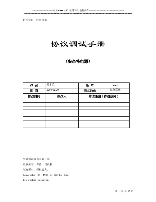
内部资料注意保密协议调试手册(安奈特电源)中兴通讯股份有限公司版权所有,保留一切权利。
版权所有,侵权必究。
Copyright (C) 1997 by ZTE Co. Ltd..All rights reserved.设备说明SM21设备接口描述(尽可能提供设备和接口图片,不同型号设备存在差别)(如何判断有无接口板、接口板外观描述)(接口类型、定义)RS232电平、DB9针、2接收、3发送、5地、(波特率、数据位、校验位、停止位)RS232电平:波特率19200、数据位8位、无校验、起始/停止位1位(操作步骤、拨码设置等)(特殊说明)调试方法pcudebug.exe(通讯是否存在时限要求、是否存在控制条件等)通道表(包括物理通道和逻辑通道)---AI通道---[交流屏数据]AI通道36(双字节1) =交流电压AAI通道37(双字节2) =交流电压BAI通道38(双字节3) =交流电压CAI通道39(双字节7) = 交流电流AAI通道40(双字节8) = 交流电流BAI通道41(双字节9) = 交流电流C[直流屏数据]AI通道27(双字节151) = 直流系统电压AI通道29(双字节153) = 负载总电流AI通道30(双字节179) = 电池1电流AI通道31(双字节193) = 电池2电流[整流屏数据]AI通道16(双字节331) = 整流模块1电流AI通道17(双字节334) = 整流模块2电流AI通道18(双字节337) = 整流模块3电流AI通道19(双字节340) = 整流模块4电流AI通道20(双字节343) = 整流模块5电流AI通道21(双字节346) = 整流模块6电流AI通道22(双字节349) = 整流模块7电流AI通道23(双字节352) = 整流模块8电流AI通道24(双字节355) = 整流模块9电流AI通道25(双字节358) = 整流模块10电流AI通道52(双字节361) = 整流模块11电流AI通道53(双字节364) = 整流模块12电流AI通道54(双字节367) = 整流模块13电流AI通道55(双字节370) = 整流模块14电流AI通道56(双字节373) = 整流模块15电流AI通道57(双字节376) = 整流模块16电流AI通道60(双字节379) = 整流模块17电流AI通道61(双字节382) = 整流模块18电流AI通道69(双字节385) = 整流模块19电流AI通道70(双字节388) = 整流模块20电流AI通道71(双字节391) = 整流模块21电流AI通道72(双字节394) = 整流模块22电流AI通道73(双字节397) = 整流模块23电流AI通道74(双字节400) = 整流模块24电流---AO通道---AO通道(双字节2617) = 块充均电压AO通道(双字节2606) = 自动均充电压AO通道(双字节2608) = 手动均充电压AO通道(双字节2615) = 一次下电电压AO通道(双字节2607) = 浮充电压AO通道(双字节2616) = 二次下电电压AO通道(双字节2610) = 自动均充时间(单位:分钟) AO通道(双字节2612) = 手动均充时间(单位:分钟) AO通道(双字节2609) = 均充周期(单位:天)AO通道(双字节2620) = 一次下电反弹电压AO通道(双字节2621) = 二次下电反弹电压---DI通道---DI通道16(双字节3000) = 监控模块故障[交流屏数据]DI通道42(双字节722) = 市电停电[直流屏数据]DI通道17(双字节924) = 均充/浮冲(0-浮充,1-均充)DI通道(双字节935) = 自动均充打开DI通道(双字节936) = 手动均充打开DI通道(双字节1006) = 温度补偿DI通道(双字节944-953) =报警继电器1-10状态DI通道40(双字节923) = 熔丝告警(0-正常,1-告警) DI通道38(双字节1026) = 一次下电DI通道39(双字节1027) = 二次下电[整流屏数据]DI通道(双字节1075) = 整流器故障(0-正常,1-故障)DI通道18(双字节1094) = 整流器1故障(0-正常,1-故障) DI通道19(双字节1119) = 整流器2故障DI通道20(双字节1144) = 整流器3故障DI通道21(双字节1169) = 整流器4故障DI通道22(双字节1194) = 整流器5故障DI通道23(双字节1219) = 整流器6故障DI通道24(双字节1244) = 整流器7故障DI通道25(双字节1269) = 整流器8故障DI通道26(双字节1294) = 整流器9故障DI通道27(双字节1319) = 整流器10故障DI通道61(双字节1344) = 整流器11故障DI通道62(双字节1369) = 整流器12故障DI通道63(双字节1394) = 整流器13故障DI通道64(双字节1319) = 整流器14故障DI通道65(双字节1344) = 整流器15故障DI通道66(双字节1369) = 整流器16故障DI通道67(双字节1394) = 整流器17故障DI通道68(双字节1419) = 整流器18故障DI通道69(双字节1444) = 整流器19故障DI通道70(双字节1469) = 整流器20故障DI通道71(双字节1494) = 整流器21故障DI通道72(双字节1519) = 整流器22故障DI通道73(双字节1544) = 整流器23故障DI通道74(双字节1569) = 整流器24故障---DO通道---DO通道(双字节2834)= 自动均充打开DO通道(双字节2835)= 自动均充关闭DO通道(双字节2836)= 手动均充打开DO通道(双字节2837)= 手动均充关闭DO通道(双字节2838)= 温度补偿打开DO通道(双字节2839)= 温度补偿关闭关键及特殊数据(特殊接收函数处理)常见故障(被监控设备监控功能是否可靠)基站名称:新村基站电源型号:DUM - 24/400I整流模块型号:DZY93 - 24/50监控模块型号:DUK - 24/50I*A监控模块生产日期:97.06监控模块编号:0037现场现象:1.电源系统整流模块显示停机,输出电流为零;电源监控模块液晶显示区域点阵紊乱,按键操作无响应;连接电源监控接口通讯无响应;确认电源监控模块已死机。
ALCATEL BSC操作维护手册

ALCATEL BSC 操作维护手册辽宁移动通信公司——————————————————————————————————————————————第 1 页/共37 页目录第1章BSC硬件介绍 (4)1.1BSC简介 (4)1.2BSC的结构 (4)1.2.1 DNS (5)1.2.2 Abis TSU (6)1.2.3 Ater TSU (7)1.2.4 Common TSU (9)1.2.5 TSCA (10)1.2.6 BCLA (11)第2章BSC操作维护手册 (11)2.1 SBL安全块 (11)2.1.1 SBL安全块概念 (11)2.1.2 SBL状态(SBL States) (12)2.1.3 SBL设备操作命令 (14)2.1.4 MO的操作命令 (15)2.2 维护案例 (16)2.2.1 BTS O&M故障处理 (16)第3章OMC-R操作与维护 (18)3.1 进入A1353RA工作程序主界面 (18)3.2 当前告警数据库(CAL) (21)3.2.1 访问当前告警管理数据库 (21)3.2.2 访问告警子数据库 (22)3.2.3 历史告警数据库(HAL) (23)3.3 伴随窗口(Follow up) (25)3.4 无线网络资源管理 (26)3.4.1访问RNUSM界面 (26)3.4.2 SC左窗口-显示所有的无线网络资源对象,分为三个子窗口: (28)3.4.3 右窗口-显示类对象(BSC、BTS、Cell、MFS...)的主要属性的描述 (28)3.4.4 如何建立左右窗口的关联性 (28)3.4.5 由于RNUSM所管理的是资源对象,故仅可进行有限的维护操作,见下表: (28)3.4.6 访问其他管理窗口 (29)——————————————————————————————————————————————第 2 页/共37 页3.5 BSS设备功能管理 (30)3.6 进程管理 (33)3.6.1 访问DSM (34)3.6.2 进程管理操作 (35)3.7 OMC-R操作维护注意事项 (35)3.7.1 注意告警消息提示 (35)3.7.2 PRC是一个非常高负荷的操作,在做这个操作时,不要使用USD。
安奈特说明
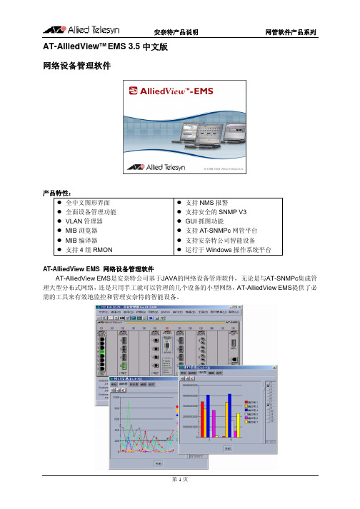
AT-S39 v3.3.1 AT-S39 v3.3.1 AT-S39 v3.3.1 AT-S39 v3.3.1 AT-S39 v3.3.1 AT-S39 v3.3.1 AT-S39 v3.3.1
安奈特产品说明 AT-8024M AT-8026FC AT-8026T AT-8088/MT AT-8088/SC AT-8124 AT-8124XL (V2) AT-8216FXL/SC AT-8224XL AT-8324 AT-8324SX AT-8326GB AT-8350GB AT-8400 AT-8403 Fan Tray for AT-8400 AT-8411 8-port (RJ-45) Line Card AT-8412 4-port (MT-RJ) Line Card AT-8412 4-port (SC) Line Card AT-8413 2-port (GBIC/RJ-45) Line Card AT-8414 4-port (SC) Line Card AT-8414 4-port (ST) Line Card AT-9006SX/SC AT-9006T AT-9410GB 4. L2+ 交换机 AT-8516F/SC AT-8524M AT-8524POE AT-8550GB AT-8550SP AT-8724XL AT-8724XL-DC AT-8748XL AT-8748XL-DC AT-9408LC/SP (new!) AT-9424T/GB AT-9424T/SP 5. L3 交换机 AT-8624POE (new!) AT-8624T/2M AT-8824 AT-8848 Rapier 16F/MT Rapier 16F/SC
安沃特mpv系列调节控制阀安装与维护说明书

MODULATING CONTROL VALVESERIES MPVINSTRUCTIONS FOR THEINSTALLATION AND MAINTENANCE1. M AIN F EATURES 22. TECHNICAL FEATURES 23. INSTALLATION 34. ELECTRIC CONNECTIONS 45. WIRING 55.1 W ITHOUT MANUAL/AUTOMATIC CONTROL STATION 55.2 W ITH MANUAL/AUTOMATIC CONTROL STATION 66. AUXILIARY MICROSWITCHES 77. POTENTIOMETER/S 78. CONTROL STATION 79. CALIBRATIONS 89.1 L IMIT SWITCH89.2 P OTENTIOMETER/S99.3 E LECTRONIC CARD109.4 M AX. CAPACITY ADJUSTMENT1110. START-UP 1111. MAINTENANCE AND CHECKS 1112. REPLACEMENT 111.MAIN FEATURESThe modulating valves in the MPV [Modulating Plug Valve] series have been designedwith a modern concept and they are DVGW approved, with CE identification number.They are suitable to be used in commercial and industrial combustion systems.They are especially suitable for the proportional adjustment of non corrosive fuel gasesfrom the first, second and third family and air. The MPV valve is an adjustment devicewithout zero closing. The actuator is equipped with a single-pole bi-directional motorwith high static torque and holding torque for 3-positional control or electronicmodulation with analogic signal current [4 ÷ 20 mA] or tension [0 ÷ 10 Vdc] variationat. The adjustment of flow volume in the valve operates by a delivery adjustingcylinder with linear characteristics. The cylinder rotation changes the passage openingand the flow volume is adjusted according to a linear trend.Three different orifice sizes are available according to the operating conditions, interchangeable without removing he valve from the plant.exclusively by skilled and authorized service technicians. Non-proper installation,adjustment, modifications, use and maintenance may cause injuries to the staff ormaterial damages. It is therefore necessary to respect strictly the followinginstructions and local prescriptions for the installation of electric and gas devices.2.TECHNICAL FEATURESOperating pressure : max. 500 mbarValve group : 2Ambient temperature : from -10 to +60°CAdjusting ratio : 25:1Fittings : Rp 1, according to ISO 7-1Delivery feature : linearValve : without zero closingAvailable voltage : 230 Vac / 50 - 60 Hz115 Vac / 50 - 60 Hz24 Vac / 50 - 60 HzNominal load : 7 VAElectric protection : IP 54 according to EN60529Duty cycle : continuous 100%Cable fasteners : 2 x Pg 13.5Opening/closing times : 30 ÷ 60 seconds at 50 HzLimit - Aux. switches rating : 5 [1] A 250 VacAvailable potentiometers : 150, 1000 [standard], 2500 ohmControl signal : 4 ÷ 20 mA [only with supply voltage 24 Vac][for electronic version]: 0 ÷ 10 Vdc [only with supply voltage 24 Vac]by-passmanualadjustable Accessories :3.INSTALLATION3.1Make sure that all the operating data shown on the valve label comply with thesystem operating data.3.2When installing the valve be sure that there is sufficient clearance above thegear cover and that it can be easily accessible in order to perform the electricalconnections and the calibration of the electric limit switches.3.3Install a filter before the MPV valve.3.4Before installing the valve, make sure the piping is clean and free of everyimpurity, and it is perfectly aligned with the valve body and not subject tovibrations.3.5Remove the protection plugs installed on the valve body.3.6The sealant must be applied only on the piping outer threading and not on thevalve inner threading. Use gas suitable sealants only.3.7Comply with the gas flow direction marked by the arrows on the valve body.3.8The MPV valve installation can be carried out in every position.3.9The MPV valve can be installed in every premise included in the range of theelectric protection IP 54, except for premises with presence of acid fumes orother vapours that can etch the metal parts, in atmosphere with gas orexplosive vapour leaks.3.10For the installation of the MPV valve on the piping do not use the actuator aslever, rather use the suitable wrench.3.11Install the MPV valve without voltage.4.ELECTRIC CONNECTIONS4.1Arrange the wiring and the grounding according to the local norms in force.4.2To access the inner terminal board and for the electric connections, remove thecover loosening the 4 fastening screws.4.3Two threaded holes for cable pressers Pg 13.5 are already arranged on thebase of the electric actuator.4.4Before servicing make sure, that power supply is disconnected by means of thetwo-pole-switch [phase and neutral]; in case of non-observance, damages topeople and equipments may occur.4.5All wires must comply with local prescriptions and, in any case, their sectionmust be ranging between 1 and 1.5 mm2. Connection piping recommendedH07V-U…G1.5 mm2.4.6Wiring diagrams are reported in the attached technical bulletin and on the plateinside the cover.4.7Auxiliary microswitches are single-pole double through and voltage-free.4.8If a potentiometer is installed, its resistance value is indicated on thenameplate.4.9Make sure the supply voltage and the system frequency correspond to thoseindicated on the valve plate.4.10Low-tension signalling cable [tension lower than 48V] must be laid separatelyfrom the higher-tension conduits [tension higher than 48V]. In case they arelaid in a single channel, screened cables must be used.5.WIRINGThe wiring schemes refer to the valve in “closed” [0°] position.5.1W ITHOUT MANUAL/AUTOMATIC CONTROL STATIONT ERMINAL BOARDTerminal earthingTerminal N1 N = neutralTerminal L2 by tension the valve closesTerminal 3 by tension the valve opensTerminal 4 for manual electric operationTerminal 16 answer signal when the valve reaches the “open” positionTerminal 17 answer signal when the valve reaches the “closed” position5.2W ITH MANUAL/AUTOMATIC CONTROL STATIONTerminal earthingTerminal 1 N = neutralTerminal 2 by tension the valve closesTerminal 3 by tension the valve opensTerminal 4 for manual electric controlTerminal 16 answer signal when the valve reaches the “open” positionTerminal 17 answer signal when the valve reaches the “closed” position microswitches6.3 AuxiliaryTerminal 20 common contact from the auxiliary microswitch S3Terminal 21 normally open contact of the auxiliary microswitch S3Terminal 22 normally closed contact of the auxiliary microswitch S3Terminal 23 common contact from the auxiliary microswitch S4Terminal 24 normally open contact of the auxiliary microswitch S4Terminal 25 normally closed contact of the auxiliary microswitch S46.4 Potentiometer/s for answer signal of the position Pot. A and/or Pot. BTerminal 30 max. valueTerminal 31 cursorTerminal 32 min. valueTerminal 33 max. valueTerminal 34 cursorTerminal 35 min. value6.AUXILIARY MICROSWITCHESOn request, the valve can be equipped with 2 auxiliary microswitches that can be adjusted in any position.Microswitches are voltage-free.The contact capacity is 5 A/250 Vac with ohmic load and 1 A/250 Vac with inductive load.Contact rating is about 5 A/250 with Ohm load and about 1 A/250 with inductive load.For adjusting the cams of auxiliary microswitches, proceed as for cams of endswitches as indicated in paragraph 9.1 chapter 9 “CALIBRATIONS”.7.POTENTIOMETER/SOn request, the valve can be equipped with 1 or 2 independent potentiometers [pot. A and/or Pot. B] for the answer signal of the valve position.Resistance value of the potentiometer is indicated on the identification label.If the resistance value does not correspond to the wished one, proceed as indicated in paragraph 9.2 of chapter 9 «CALIBRATIONS».Absorbed power is 2 W for each potentiometer.8.CONTROL STATION8.1The control station enables the manual electric activation of the valve.8.2Phase L must be connected to the terminal no. 4.8.3The AUTO/MAN switch is delivered by the factory in AUTO position .8.4Set the AUTO/MAN switch in the manual position indicated by stylized hand8.5Activate the Open/Stopped/Closed switch as follows:8.5.1Keeping the lever pushed towards the symbol ◄ the valve opens [the cam S2adjusts the desired final opening position].8.5.2Keeping the lever pushed towards the symbol ►the valve closes [the cam S1adjusts the desired final closing position].8.5.3Positioning the lever to the centre, the valve motor is not activated.8.5.4ATTENTION: after the operations for manual electric activation of the valve,reset the AUTO/MAN switch onto AUTO position .9.CALIBRATIONS9.1L IMIT SWITCH9.1.1The MPV valve is delivered by the factory in closed position. The limit switchesare adjusted to reach the positions of closed valve and completely open valve.9.1.2For “OPEN” position adjustment, it is necessary to operate on cam “S2”.9.1.3For cam adjustment, use the proper “half-moon” key, supplied with theactuator and installed inside it.9.1.4Use the key from the right side, introducing the pin into one of the holes onthe sides of the blue cam of the cam involved and lever it to required position.9.1.5If the blue cam is in a behind position, use at first the lever on its curved sideto move the blue cam to a more suitable position to perform adjustment[picture 1].Picture 19.1.6To calibrate, refer to the mechanical position indicator disc; the valve is closedwhen the mechanical pointer is in the 0 position, the valve is completely openwhen the mechanical pointer is in the 90° position.9.1.7The cam adjustment is possible in both directions.9.1.8The lever roller operates the microswitch when it is on the bottom of the camgroove, stopping the motor rotation.9.1.9Remove the wrench before starting the actuator.9.1.10 The movable crown can be driven also by a small screwdriver, acting on thesuitable notches.9.1.11 Avoid valve rotation over 90°, in order to prevent damage on the adjustingcylinder, and/or force the potentiometer shaft rotation.9.2P OTENTIOMETER/S9.2.1 The potentiometer shaft is frictioned and is accessible from the upper sideinside the gear motor.9.2.2 Disconnect the cables connected with the regulation system from therespective terminals n. 30, 31 and 32 [Pot. A] and, if necessary, n. 33, 34 and35 [Pot. B].9.2.3By means of a suitable screwdriver with 5 mm cut rotate the potentiometershaft and measure the resistance value of 0 Ohm between terminals n. 31 and32 and, if necessary, also between terminals n. 34 and 35 when the valve isclosed [picture 2].2Picture9.2.4By rotating the potentiometer:● clockwise 3the resistance value increases● counter dock wise 4the resistance value decreases9.2.5The gearbox between the gear motor shaft and the potentiometer shaft isforeseen for a 90° rotation angle between closed valve and totally open valve.Hence should the gear motor opening be reduced with a rotation angle lowerthan 90°, the variation of the potentiometer resistance value will beproportionally reduced.If, vice versa, the rotation angle had been wrongly adjusted over 90° therewill be no increase in the resistance value beyond the plate maximum value.9.3E LECTRONIC CARD9.3.1Supply the servocontrol as per schema SE.9.3.2Select the MAN function9.3.3Position the adjustment instrument on 4 mA [or on 0 Vdc].9.3.4Turn the servocontrol manually till reaching the mechanical zero.9.3.5Adjust the closing cam «S1» at few degrees before microswitch involvement.9.3.6Turn the potentiometer shaft clockwise 3 till it stops mechanically.9.3.7Select the AUTO position9.3.8Set the adjustment device on 6 mA [or on 2 Vdc] and wait up the servocontrolmoves, then take it back to 4 mA [or on 0 Vdc] and check it reaches 0 degrees.9.3.9If it does not exactly come back to 0 degrees, turn the potentiometer shaftcounterclockwise 4 till 0 degrees.9.3.10 Set the adjustment device at 20 mA [or on 10 Vdc] and check the max.opening, then calibrate the opening cam «S2» at few degrees before themicroswitch involvement.9.3.11 Set the adjustment device on 4 mA [or on 0 Vdc] regulating the servocontrolback to 0 degrees.9.4M AX. CAPACITY ADJUSTMENT9.4.1To reduce the max. capacity fit a 3 mm hexagon socket screw in the suitableseat on the lower part of the valve body and rotate it counterclockwise 4.9.4.2The MPV valves are supplied by the factory adjusted for the max. capacity.10.START-UP10.1Before starting the system up, carefully check the following points of the MPVvalve:- correct installation according to the flow direction- gas outer seals- correct electric connections and grounding- perfect electric and mechanical operation by opening and closing with closed gas main cock.Once preliminary conditions compliance, the gas main cock can be opened andthe operating test can be carried out.11.MAINTENANCE AND CHECKS11.1The MPV valve does not require any special maintenance.Both the valve body and the actuator do not need any lubrication.11.2 At least once a year, and above all for systems subject to vibrations, it isrecommended to check the harness for faulty contacts of the terminal boardand to tighten the screws.12.REPLACEMENTFor replacement of MPV valve, operate as follows:12.1Close the gas main cock.12.2Cut off the supply voltage to the valve.12.3Remove the actuator cover.12.4Disconnect all the electric connections, noting the cable numbers.12.5Remove the valve body from the piping.12.6Install the new valve according to the instructions of the previous chapters. These instructions can be subject to possible variations without notice.11 of 11。
INANTERSIMS帮助

INANTER-SIMS2000综合安防集成管理平台安装说明本用户手册没有任何形式的担保及承诺。
若因此用户手册或者是所提及的产品信息,而引起的直接或间接的数据丢失、利益损失或事业终止,或者是因任何安装使用不当造成的直接、间接、有意、无意损坏及隐患,英安特公司及所属员工恕不为其担负任何责任。
此外,本手册所提及的软件功能仅供参考,本手册可能包含技术上不准确的地方或印刷错误。
我们将会随时改进或更新本手册中描述功能或程序,本手册的内容也将做定期的版本更新,恕不另行通知,更新的内容将会在本手册的新版本中加入。
本手册涉及的各种名称仅做识别之用,这些名称可能属于其他公司的商标或版权。
目录INANTER-SIMS2000最终用户软件许可协议 (5)前言 (9)一、参考材料以及书目 (9)二、INANTER-SIMS2000软件运行环境要求 (9)三、数据库系统 (10)SIMS2000综合安防网络集成管理平台简介 (11)如何应用SIMS2000综合安防网络集成管理平台 (12)一、二级中心应用 (12)二、一级中心应用 (13)安装SIMS2000综合安防网络集成管理平台的条件 (13)第一章MS SQL Server 2000个人版数据库安装 (14)第二章MS SQL Server 2000 SP4补丁安装 (23)第三章MS SQL Server 2000 SP4 补丁安装后的网络测试 (32)3.1 看ping 服务器IP能否ping通 (32)3.2 在DOS或命令行格式下的测试 (32)3.3 检查客户端设置 (33)3.4 企业管理器或查询分析器连接测试 (34)3.5 错误产生的原因 (34)第四章INANTER-SIMS2000 软件安装 (35)第五章INANTER-SIMS2000 数据库安装 (41)5.1 自动安装数据库 (41)5.2 手动安装数据库 (42)第六章软件授权设备的安装 (45)第七章INANTER-SIMS2000 软件服务的安装 (46)7.1 安装及启动软件授权服务 (46)7.2 安装及启动安装语音服务器 (46)7.3 安装及启动SIMS2000-RMS注册服务器 (46)7.4 安装及启动SIMS2000-VBUS通讯服务器 (46)第八章INANTER-SIMS2000 平台软件操作使用说明 (47)8.1 运行前的准备 (47)8.2 SIMS2000-RMS注册服务器(仅在大联网时使用) (47)8.3 SIMS2000-Config设置管理系统 (48)8.3.1 站点授权 (49)8.3.2 电子地图 (50)8.3.3 报警管理 (55)8.3.4 模拟矩阵 (67)8.3.5 数字视频 (71)8.3.6 巡更管理 (76)8.3.7 门禁管理 (79)8.3.8 对讲管理 (81)8.3.9 系统用户 (84)8.4 SIMS2000-VBUS Service通讯服务器 (87)8.4.1 系统设置 (88)8.4.2 事件日志 (88)8.4.3 报警系统 (89)8.4.4 巡更系统 (90)8.4.5 模拟矩阵 (90)8.4.6 门禁系统 (91)8.4.7 对讲系统 (93)8.5 SIMS2000综合安防网络集成管理平台 (94)8.5.1 软件登录 (94)8.5.2 界面按钮介绍 (95)8.5.3 电子地图 (95)8.5.4 报警系统 (96)8.5.5 模拟矩阵 (97)8.5.6 数字视频 (98)8.5.7 扩展工具 (100)8.5.8 查询历史记录 (100)第九章系统故障珍断 (104)9.1 Generic Host Process for Win32 Services 错误 (104)9.2 Windows 安全警报 (106)(一) 关闭Windows XP的防火墙 (106)(二) 将应用程序添加到windows防火墙例外设置中 (110)第十章网络模块设置 (113)10.1 AW-NC100及AW-NC200M设置 (113)10.2 IP2000的编程及设置 (117)10.3 IPM的编程及设置 (119)10.4 DVSAlarm的设置与使用 (123)第十一章一级中心联网络系统安装 (123)11.1 安装概述 (123)11.2 一级中心与二级中心联网示意图 (124)11.3 二级中心的设置 (124)11.4 一级中心安装MS SQLSERVER数据库 (125)11.5 一级中心软件安装 (125)11.6 一级中心软件运行设置步骤 (132)INANTER-SIMS2000最终用户软件许可协议重要须知——请认真阅读本《最终用户许可协议》(一下称《协议》)是您(个人或单一机构团体)与南京英安特科技实业有限公司(以下简称英安特)之间有关上述INANTER-SIMS2000“软件产品”的法律协议。
安奈特中文操作指南
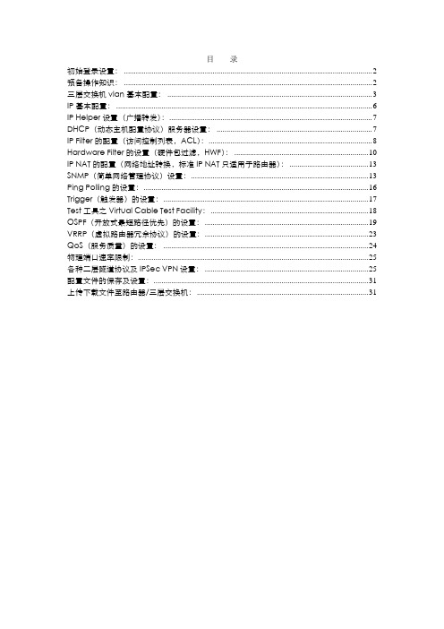
目录初始登录设置: (2)预备操作知识: (2)三层交换机vlan基本配置: (3)IP基本配置: (6)IP Helper设置(广播转发): (7)DHCP(动态主机配置协议)服务器设置: (7)IP Filter的配置(访问控制列表,ACL): (8)Hardware Filter的设置(硬件包过滤,HWF): (10)IP NAT的配置(网络地址转换,标准IP NAT只适用于路由器): (13)SNMP(简单网络管理协议)设置: (13)Ping Polling的设置: (16)Trigger(触发器)的设置: (17)Test工具之Virtual Cable Test Facility: (18)OSPF(开放式最短路径优先)的设置: (19)VRRP(虚拟路由器冗余协议)的设置: (23)QoS(服务质量)的设置: (24)物理端口速率限制: (25)各种二层隧道协议及IPSec VPN设置: (25)配置文件的保存及设置: (31)上传下载文件至路由器/三层交换机: (31)####################################################################### 初始登录设置:####################################################################### 使用超级终端通过串口登录进入路由器/三层交换机。
超级终端设置:9600波特率,8数据位,1停止位,No奇偶校验,硬件流控制。
在login:状态输入用户名:manager密码:friend如果有相应权限,也可通过telnet路由器/三层交换机的任意活跃接口的IP地址访问设备。
安奈特路由器/三层交换机的配置环境是不区分层次化的,不存在类似Cisco的“全局配置模式”、“接口配置模式”、“路由协议配置模式”……,所有的配置命令均在同一模式/界面下执行,其提示符为:登录用户级别设备名称>例如,使用Manager权限用户登录名称为Test的设备,则显示为:Manager Test>使用SecurityOfficer权限用户登录名称为CoreSwitch的设备,则显示为:SecOff CoreSwitch>然后即可配置所有内容。
- 1、下载文档前请自行甄别文档内容的完整性,平台不提供额外的编辑、内容补充、找答案等附加服务。
- 2、"仅部分预览"的文档,不可在线预览部分如存在完整性等问题,可反馈申请退款(可完整预览的文档不适用该条件!)。
- 3、如文档侵犯您的权益,请联系客服反馈,我们会尽快为您处理(人工客服工作时间:9:00-18:30)。
编号:_______________本资料为word版本,可以直接编辑和打印,感谢您的下载
深圳安耐特Enatel(SM21)协议调试手册
甲方:___________________
乙方:___________________
日期:___________________
协议调试手册
(安奈特电源)
中兴通讯股份有限公司
版权所有,保留一切权利。
版权所有,侵权必究。
Copyright (C) 1997 by ZTE Co. Ltd-
All rights reserved.
设备说明
设备名称:安奈特电源
设备型号:
监控模块型号:SM21
协议资料版本:
供应商资料:
适用型号:
设备接口描述
图片资料:(尽可能提供设备和接口图片,不同型号设备存在差别)
通讯接口板说明:(如何判断有无接口板、接口板外观描述)
接口定义:(接口类型、定义)
RS232电平、DBM 2接收、3发送、5地、
接口参数:(波特率、数据位、校验位、停止位)
RS232电平:波特率19200、数据位8位、无校验、起始/停止位1位
监控模块操作及接口参数设置:(操作步骤、拨码设置等)
其他:(特殊说明)
调试方法
PcuDebug 名称: pcudebug.exe
供应商测试软件使用说明:
手动测试数据:
测试技巧及注意事项:(通讯是否存在时限要求、是否存在控制条件等)
通道表(包括物理通道和逻辑通道)
---AI 通道---
[交流屏数据]
AI 通道36 (双字节 AI 通道37 (双字节 AI 通道38 (双字节 AI 通道39 (双字节 AI 通道40 (双字节 AI 通道41 (双字节
[直流屏数据]
AI 通道27 (双字节 AI 通道29 (双字节
AI 通道30 (双字节
AI 通道31 (双字节 1) =交流电压A 2) =交流电压B 3) =交流电压C 7) =交流电流A 8) =交流电流B 9) =交流电流C
151)=直流系统电压 153)=负载总电流
179)=电池1电流
193)=电池2电流
[整流屏数据]
AI 通道16 (双字节331) AI 通道17 (双字节334) AI 通道18 (双字节337) AI 通道19 (双字节340) AI 通道20 (双字节343) AI 通道21 (双字节346) AI 通道22 (双字节349) AI 通道23 (双字节352) AI 通道24 (双字节355) AI 通道25 (双字节358)
AI 通道52 (双字节361)=整流模块11电流
AI 通道53 (双字节364)=整流模块12电流
整流模块1电流 整流模块2电流 整流模块3电流 整流模块4电流 整流模块5电流 整流模块6电流 整流模块7电流 整流模块8电流 整流模块9电流 整流模块10电流。