MOSFET Basic
MOSFET用作开关时的特性与计算方法

4.9功率型MOSFET用作开关(THE POWER MOSFET USED AS A SWITCH)4.9.1概论(Introduction)虽然场效应电晶体(field-effect transistor FET)应用于电路设计上己有许多年了,而近年来功率型金属氧化半导体场效应电晶体(metal-oxide-semiconductor field-effect transistor MOSFET),也己成功地制造出来,并在商业上大量的应用于功率电子的设计上。
而此MOSFET的功能需求,更超越了其它的功率组件,工作频率可达20kHz以上,一般都工作于100-200kHz,而不需像双极式功率电晶体有诸般经验上的限制。
当然,如果我们设计转换器工作于100 kHz频率下,比工作于20kHz的频率会有更多的优点,最重要的优点就是能减少体积大小与重量,功率型MOSFET提供设计者一种高速度,高功率,高电压,与高增益的组件,且几乎没有储存时间,没有热跑脱与被抑制的崩溃特性,由于不同的制造厂商会使用不同的技术来制造功率型的FET,因此就会有不同的名称,如HEXFET,VMOS,TMOS 等,此乃成为每一公司特有的注册商标。
虽然结构上会有所改变而增强了某些功能,但是所有的MOSFETs基本的工作原理都是相同的,事实上对某些应用上来说,使用特有型式的MOSFET有时亦会较使用其它型式来得适切引人些。
4.9.2基本MOSFET的定义(Basic MOSFET Definitions)MOSFET的电路符号示于图4-16中,此为N通道的MOSFET,在图4-16中另一个为NPN双极式电晶体,可互相参考比较其符号之不同,当然亦有P通道的MOSFET,其电路符号中的箭头方向刚好与N通道相反,在图4-16的这二个电路符号,双极式电晶体的集极,基极,与射极端,就相对于MOSFET的漏极,栅极与源极端。
虽然此二者组件都称为电晶体,可是我们必须明了,双极式组件与MOSFET,在结构上与操作原理上还是有明显的不同。
MOS晶体管基本特性表征

0.00025 0.0002
Vgs=0.3V Vgs=0.6V Vgs=0.9V Vgs=1.2V Vgs=1.5V
0.00015
线性区
0.8 1 1.2 Vg(V)
Ion
饱和区
Ids (A)
0.0001
• MOSFET最主要的特性曲线为Id-Vg, Id-Vd曲线. 特别是Id-Vg;
0.00005
Ids (A)
5.00E-03 4.00E-03 3.00E-03 2.00E-03
1.00E-12 -0.2 0 0.2 0.4 0.6 0.8 1 1.2 Vgs (V)
1.00E-03
0.00E+00 0
Id (A)
Id (A)
Vt2@1E-7*W/L
Vd=-0.1V Vd=-1.2V
5.00E-03
1. 沟道越短,DIBL越大;
2. DIBL有时会表现为亚阈摆幅增大, 即 增加Ioff;
1.00E-05 1.00E-06
3. DIBL会降低输出电阻, 使器件用于模 拟电路特性变差, 用于数字电路速度下 降.
1.00E-07 1.00E-08 1.00E-09
1.00E-02
0
0.15um LV,
4.00E-03 3.00E-03
Vd=-0.1V Vd=-1.2V
2.00E-03
1.00E-03
0.00E+00
0.2
0.4 0.6 0.8 1 0 0.2 0.4 0.6 0.8 1 1.2
MOSFET Basic Characterization
(MOS晶体管基本特性表征)
Wenyu Gao 2020/04/18
MOSFET测试模板

MOSFET测试模板MOSFET 测试报告FSXXXX-X(A、B…)Basic InformationTest purpose :(例如:对⽐测试,验证参数、、、、、、)Pin ConfigurationsBlock DiagramTest Circuit(以下仅为推荐测试⽅法,根据具体情况可做相应的改动)1、漏源击穿电压 1.1测试电路Category (产品分类)Package (封装类型) PN (产品型号)Operator (测试⼈) Marking (打印) SN (样品编号) Compare Sample (对⽐样品) Test Date (测试⽇期)Test Equipment (测试设备)Demo board And Fixture(治具)Reference (测试参照)(竞争对⼿DATASHEET ,本公司DATASHEET ,本公司测试模板)1.2测试程序按上图连接好电路,调节直流电源⾄电流表读数为ID规定值时为⽌,电压表读数即为源极和漏极间的崩溃电压。
2、门限阈值电压2.1测试电路2.2测试程序按上图连接好电路,调节直流电源DC⾄电流表读数为ID规定值时为⽌,读出电压表读数,即为栅极开启电压。
3、漏源漏电流3.1测试电路3.2测试程序按上图连接好电路,调节直流电源DC ⾄VDS 规定值,读出电压表数值,根据欧姆定律I=U/R 可计算出漏极电流(由于所测电流为nA 级,电流表精度不够,所以采⽤公式计算的⽅式测试) 4、栅源漏电流 4.1测试电路4.2测试程序按上图连接好电路,调节直流电源DC ⾄VGS 规定值,读出电压表数值,根据欧姆定律I=U/R 可计算出栅极与源极间正向漏电流(由于所测电流为nA 级,电流表精度不够,所以采⽤公式计算的⽅式测试)。
5、导通电阻5.1测试电路(为了便于测试调试,建议选择电阻约为所测R DS (ON )⼗倍)5.2测试程序按上图连接好电路,调节信号发⽣器⾄VGS规定值(使⽤脉冲波), 调节直流电源DC使通过电流探头的电流为ID规定值, 根据欧姆定律R=U/I可计算出导通电阻(其中U为⽰波器上的电压值,I为通过电流探头的电流值)6、跨导6.1测试电路6.2测试程序(占空⽐1.9%,频率50Hz)按上图连接好电路,调节信号发⽣器(使⽤脉冲波)和DC电源⾄VDS与ID规定值,再调节脉冲波的幅值,记录下脉冲波幅值的变化量(△V GS)和I D的变化量(△I D) G FS=△I D/△V GS7、输⼊电容7.1测试电路7.2测试程序按上图连接好电路,调节电桥的频率⾄Frequency规定值,读出电桥上的电容值(即输⼊电容)8、输出电容8.1测试电路8.2测试程序按上图连接好电路,调节电桥的频率⾄Frequency规定值,读出电桥上的电容值(即输⼊电容)9、弥勒电容9.1测试电路9.2测试程序按上图连接好电路,调节电桥的频率⾄Frequency规定值, 弥勒电容C U按照下⾯的公式来计算:(C K为电路中所接电容容值,C M为电桥的测量值)10、上升延时时间,上升时间,下降延时时间,下降时间10.1测试电路10.2测试程序按上图连接好电路,分别测量V DS,V GS的波形,其波形如下(上升延时时间,上升时间,下降延时时间,下降时间,分别做了标注):11、⼆极管正向导通电压11.1测试电路11.2测试程序按上图连接好电路,调节直流电源⾄电流表读数为ID规定值时为⽌,电压表读数即为⼆极管正向导通电压Electrics Characteristics @ TA = 25°C unless otherwise specifiedParameterSymbol Test Conditions Min Typ Max UnitOFF CHARACTERISTICSDrain-Source Voltage BV DSS V GS =0,I D =250uA V Drain Cut-off CurrentI DSS V DS = V , V GS = 0VuA Gate - Body Leakage, Forward I GSSF V GS = V nA Gate - Body Leakage, ReverseI GSSRV GS = VnAON CHARACTERISTICSGate Threshold VoltageV GS(th ) I D = uA , V DS = V GSVDrain-Source On-state Resistance R DS(on) I D = A , V GS =V m Ω I D = A , V GS = Vm ΩForward TransconductanceG FSV DS =V, I D = mASDYNAMIC CHARACTERISTICSInput Capacitance C iss V DS = V , V GS = 0Vf = MHzpF Output Capacitance C oss pF Feedback CapacitanceC rsspFSWITCHING CHARACTERISTICSTurn-on Delay Time t d ( on ) V GS =V , I D = A V DD = Vns Rise TimeT r ns Turn-off Delay Time t d( off ) ns Fall Timet fnsDRAIN-SOURCE DIODE CHARACTERISTICS AND MAXIMUM RATINGS Drain-Source Diode Forward VoltageV SD Is = A, V GS = 0VVTypical Performance Characteristics1. Output Characteristics(Drain current VS Drain-source voltage)2. Transfer Characteristics(Drain current VS Gate-source voltage)3. On-Resistance vs. Drain Current4. Capacitance(Drain-source voltage VS Capacitance)5. On-Resistance vs. Junction Temperature6. Source-Drain Diode Forward Voltage7.On-Resistance vs. Gate-to-Source Voltage8.Threshold Voltage VS Temperature 9. Single Pulse Power(Power VS Time) ESD Characteristics(Option)Attachment(附件):Abnormal Phenomena analysis(异常现象分析): Function test(功能测试) Conclusion(结论):。
mosfet的基本参数

mosfet的基本参数MOSFET(金属氧化物半导体场效应晶体管)是一种常用的场效应晶体管,广泛应用于电子设备中。
它具有许多基本参数,这些参数对于了解和设计电路至关重要。
本文将重点介绍MOSFET的基本参数,包括漏极电流、漏极电压、栅极电流、栅极电压和沟道电阻。
1. 漏极电流(ID):漏极电流是MOSFET中最基本的参数之一,它表示通过漏极的电流。
漏极电流的大小取决于栅极电压和漏极电压之间的差异,以及MOSFET的结构和工作状态。
漏极电流可以通过控制栅极电压来调节,从而实现对MOSFET的控制。
2. 漏极电压(VDS):漏极电压是MOSFET的另一个重要参数,它表示在漏极和源极之间的电压。
漏极电压的大小对MOSFET的工作状态和性能具有重要影响。
当漏极电压超过一定值时,MOSFET将进入饱和区,此时漏极电流基本保持不变。
如果漏极电压进一步增加,MOSFET将进入截止区,漏极电流将急剧减小。
3. 栅极电流(IG):栅极电流是通过栅极的电流,它对MOSFET的控制起着重要作用。
栅极电流的大小取决于输入信号的特性以及MOSFET的工作状态。
通过控制栅极电流的大小,可以调节MOSFET的导通能力和开关速度。
4. 栅极电压(VGS):栅极电压是MOSFET的另一个关键参数,它表示栅极与源极之间的电压。
栅极电压的变化可以改变MOSFET的导通能力和截止状态。
当栅极电压超过一定值时,MOSFET将开始导通,形成一个通路。
如果栅极电压低于一定值,MOSFET将截止,电流无法通过。
5. 沟道电阻(RDS(on)):沟道电阻是MOSFET的内部电阻,它表示MOSFET导通状态下沟道的电阻大小。
沟道电阻的大小对于MOSFET的导通能力和功耗具有重要影响。
较小的沟道电阻意味着更好的导通性能和更低的功耗。
MOSFET的基本参数包括漏极电流、漏极电压、栅极电流、栅极电压和沟道电阻。
这些参数对于设计和控制电路至关重要,可以通过调节栅极电压和栅极电流来改变MOSFET的工作状态和性能。
MOSFET Basics

controlled by the gate-source voltage VGS. For a sufficiently high VGS, an internal current path, called the channel, is established between the drain and the source. The higher the VGS value the easier it is to flow for the drain-source current IDS. Note that the only DC current in the MOSFET is IDS since the gate is internally insulated from the channel. By operating the MOSFET in particular bias regions, based on the VGS, VDS, and IDS values, it can be used to perform a variety of functions. The two regions that the MOSFET device can operate in are the ohmic (linear) and saturation (active) regions. Both of these regions will be explored in this experiment through the exploration of a few of the MOSFET device implementations. These regions can be graphically represented. Shown in Figure 4 is the MOSFET IDS vs. VDS curve for constant values of VGS. Notice that the ohmic region exists where VDS is very small and the curve is nearly linear, hence another name for the region is the linear region. As VDS increases, the curve begins to flatten. When VDS is equal to the saturation voltage, VDSAT, the device enters the saturation region. This voltage, VDSAT, is determined by the voltage VGS of the MOSFET along with a physical parameter of the MOSFET called the threshold voltage VT.
MOSFET基础知识介绍

MOSFET基础知识介绍MOSFET(金属氧化物半导体场效应晶体管)是一种常用的半导体器件,用于在电子电路中控制电流的流动。
它由金属氧化物半导体结构组成,具有高输入阻抗、低功耗和高电压承受能力等优点,因此在各种应用中广泛使用。
MOSFET的结构包括有源区、漏源区、栅极和绝缘层等部分。
有源区通常由P型半导体材料组成,而漏源区则是N型或P型半导体材料。
两个区域之间的绝缘层是一个非导电的氧化物层,通常是二氧化硅。
栅极是一个金属或多晶硅的电极,用于控制电流的流动。
MOSFET的工作原理基于栅极电压的控制。
当栅极电压为零或低于临界电压时,MOSFET处于截止状态,无法通过电流。
当栅极电压高于临界电压时,介质中的电场会引起有源区附近的载流子(电子或空穴)移动,形成导电路径。
这时,MOSFET处于饱和状态,可以通过电流。
MOSFET有两种常用的工作模式,分别是增强型和耗尽型。
在增强型MOSFET中,栅极电压高于临界电压时,会导致有源区中的载流子浓度增加,从而提高电流的导电能力。
而在耗尽型MOSFET中,栅极电压低于临界电压时,会减少有源区中的载流子浓度,从而减小电流的导电能力。
另一个重要的参数是漏极漏电流。
当MOSFET处于截止状态时,理想情况下应该没有电流通过,但实际上会存在微小的漏电流。
漏极漏电流越小,MOSFET的性能越好。
MOSFET还有一些特殊类型,例如增压型MOSFET和均衡型MOSFET。
增压型MOSFET通过增加外加电压来提高导电能力。
均衡型MOSFET则可以在两个有源区之间实现均衡的电流分布,以提高功率放大器的线性度。
MOSFET在各种应用中都有重要的作用。
在数字电路中,MOSFET可以作为开关使用,用于控制逻辑门和存储器等器件的操作。
在模拟电路中,MOSFET可以作为放大器使用,用于控制电压和电流的变化。
此外,MOSFET还常用于功率放大器、电源和开关模式电源等领域。
总而言之,MOSFET是一种重要的半导体器件,具有高输入阻抗、低功耗和高电压承受能力等优点。
mos场效应管简介及原理(英文)

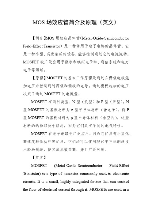
MOS场效应管简介及原理(英文)【简介】MOS场效应晶体管(Metal-Oxide-Semiconductor Field-Effect Transistor)是一种常用于电子电路的晶体管。
它是一种小型、高度集成的设备,能够控制通过它的电流流动。
MOSFET被广泛应用于数字和模拟电子学、通信系统和电力电子等领域。
【原理】MOSFET的基本工作原理是通过在栅极电极施加电压来控制通过源极和漏极的电导。
通过栅极施加的电压决定了通过MOSFET的电流量。
MOSFET有两种类型:N型(负型)和P型(正型)。
N 型MOSFET的基板材料为n型半导体材料(含电子),而P 型MOSFET的基板材料为p型半导体材料(含空穴)。
这些材料的选择取决于应用,因为它们具有不同的电气特性。
MOSFET在电子电路中广泛应用,因为它们具有小型化、高速度和低功耗等优点。
它们还可以使用现代半导体制造技术轻松制造,使其成本效益高,并且广泛可用。
【英文】MOSFET (Metal-Oxide-Semiconductor Field-Effect Transistor) is a type of transistor commonly used in electronic circuits. It is a small, highly integrated device that can control the flow of electrical current through it. MOSFETs are used in awide range of applications, including digital and analog electronics, communication systems, and power electronics.The basic principle of operation of a MOSFET is that it controls the flow of electrical current through the gate electrode, which is insulated from the source and drain by a thin oxide layer. When a voltage is applied to the gate electrode, a current flows through the channel between the source and drain, causing the MOSFET to conduct electricity. The voltage applied to the gate electrode determines the amount of current that flows through the MOSFET.There are two main types of MOSFETs: N-type (for negative) and P-type (for positive). N-type MOSFETs have an n-type semiconductor material (containing electrons) as the substrate, while P-type MOSFETs have a p-type semiconductor material (containing holes) as the substrate. These types of materials are chosen based on the application, as they have different electrical properties.MOSFETs are widely used in electronic circuits because of their small size, high speed, and low power consumption. They are also easy to fabricate using modern semiconductor manufacturing techniques, making them cost-effective and widely available.。
MOS晶体管基本特性表征

短沟MOSFET— I-V 特性曲线
DIBL (drain induced barrier low):
σ = |Vt1 – Vt2| / |Vdd-0.1| 1. 2. 3. 沟道越短,DIBL越大; DIBL有时会表现为亚阈摆幅增大, 即 增加Ioff; DIBL会降低输出电阻, 使器件用于模 拟电路特性变差, 用于数字电路速度下 降.
Ids (A)
5.00E-03 4.00E-03 3.00E-03 2.00E-03 1.00E-03
0
0.2
0.4 0.6 Vgs (V)
0.8
1
1.2
0.00E+00 0 0.3 0.6 0.9 1.2 1.5 上海宏力半导体制造有限公司 Vds(V)
9 Confidential
Grace Semiconductor Manufacturing Corporation
上海宏力半导体制造有限公司 Grace Semiconductor Manufacturing Corporation
5 Confidential
I-V 特性曲线 线性区(萨氏方程):
L C W s ox L V Rch ds (V gs Vth ) I ds I ds
Ioff 1.00E-10
1.00E-11 1.00E-12 0 0.2 0.4
C Cit C Cit S 2.3Vt (1 d ) 60m V(1 d ) Cox Cox
Vth V fb 2 f 2 f Vsb
1. 2.
0.6
0.8
0.15um LV, W/L=10/10
Vgs Vth
Id (A)
5.00E-05 4.00E-05 3.00E-05 2.00E-05 1.00E-05
- 1、下载文档前请自行甄别文档内容的完整性,平台不提供额外的编辑、内容补充、找答案等附加服务。
- 2、"仅部分预览"的文档,不可在线预览部分如存在完整性等问题,可反馈申请退款(可完整预览的文档不适用该条件!)。
- 3、如文档侵犯您的权益,请联系客服反馈,我们会尽快为您处理(人工客服工作时间:9:00-18:30)。
2 High side Conduction Loss
Psw
1
Iout Vin t r t f f sw
MOSFET Basics
1
Lateral MOSFET
Cross- section of a Laterally Diffused MOSFET (LDMOS) structure
2
VMOSFET and UMOSFET
Cross- section of two vertical MOSFET structures: VMOS and UMOS
3
Operation of MOSFET
A MOSFET driven by a gate voltage
Formation of depletion region
Vg
+
0.1V
Vg
+
0.1V
P+
N+
N+
P+
N+
------
N+
P-substrate
P-substrate
Formation of inversion layer ( Vg ++)
Vd
Io
Io
Cgd
+
Vg
Rg
Cgd
+
Vg
Rg Rds(on)
equivalent circuit of period t2 – t3
equivalent circuit of period t3 – t4
16
MOSFET Power Dissipation for DC-DC Converter High Side Switching Loss
time
SW1
Drain Voltage VDS
Drain Current
ID
Basic Gate Charge Test Circuit
Mechanics of the Test:
Gate Charge Waveforms
3.a.) The DUT is tested given the Vds, and Id forced conditions. 3.b.) The Ig is usually applied from a constant current source as shown in the simplified layout. The Ig is usually selected at either 1mA or 100uA depending on the die size of the DUT. 3.c.) The Id is also applied based on the programmed Id conditions. 3.d.) The Qgs, Qgd, and total Qg are measured based on the graphs to the right showing the time. The charge, Q, is simply taken from the equation: q = i x t (Ig current x time).
iD
Ohmic
[VGS – VGS(th) = VDS] Active VGS5 VGS5>VGS4>VGS3>VGS2>VGS1 VGS4 VGS3 VGS2 VGS1 Cut Off
VGS<VGS(TH)
0 Output Characteristics
BVDSS
VDS
14
The graph of Vgs, Ig, Vds and Id when MOSFET turn on
Gate Charge Measure
Gate Charge Test (Equipment used: Bench Power supplies, Oscilloscope, and Home-brewed circuit)
VDS
ID
VG
QGS
QG QGD
IG
CGD
DUT
CGS
VTH
t0 t1 t2 t3 t4
18
The Path of the Thermal Discharge at the Chip Junction
PD
RJC RCS RSAFra bibliotekfsw : switching frequency
tr : switching rise time tf : switching fall time
P : phase No. (interleave no.) ILripple : inductor current (pk-pk) D : duty cycle Vf : Schottky or body diode forward Voltage
8
MOSFET’s Parasitic Capacitance
9
Ciss Measure
Capacitance Tests (Equipment used: Bench power Supplies and Agilent HP4194A or Boonton Meter 72B)
7.6mH
DUT 1000pF 30F 0.1F HI
10
Crss Measure
2mH HI
VDS
0.1F
DUT LO
CRSS Test Circuit
Mechanics of the Tests a.) The HI and LO terminals, as shown on each test setup above, are to be connected to the Hi and Lo terminals of the Capacitance meter. You can use either the Boonton or Agilent capacitance meters. b.) The Vds is turn-on given the specific forcing condition as defined in the specs. c.) The capacitance value is simply taking the results as displayed on the meter being used. 11
Coss Measure
2mH HI
VDS
0.1F
DUT
LO
COSS Test Circuit
Mechanics of the Tests a.) The HI and LO terminals, as shown on each test setup above, are to be connected to the Hi and Lo terminals of the Capacitance meter. You can use either the Boonton or Agilent capacitance meters. b.) The Vds is turn-on given the specific forcing condition as defined in the specs. c.) The capacitance value is simply taking the results as displayed on the meter being used. 12
1 4
Vf f sw ILripple t f t r
Pcon
Iout RDS(ON) (1 D)
2
High side Power loss=Psw+Pcon
Low side Power loss=Pcon+Psw(ignored if small enough)
VDS
LO
CISS Test Circuit
Mechanics of the Tests
a.) The HI and LO terminals, as shown on each test setup above, are to be connected to the Hi and Lo terminals of the Capacitance meter. You can use either the Boonton or Agilent capacitance meters.
Depletion capacitance
Vg
+++
0.1V
Vg
+++
0.1V Cox
P+ P-substrate
N+
------
-------------
N+
P+ P-substrate
N+
Cdep
N+
4
Drain-source on Resistance ( RDS(ON) )
RDS(on) = RN+ + RCH + RA + Rj + RD + RS
3.e.) SW1 is used to discharge the Gate charge after every test is conducted.
13
MOSFET Output Characteristics
Ohmic region : Constant Resistance Region. Saturation region : Constant Current Region. Cut-off region : It is called Cut-Off Region.
