ESC_RTP58
施耐德变频器

双极性模拟输入 0 ±10V (最高安全电压 ±30V) AI2 上电压的 + 或 - 极性会影响设定点的方向,继而影响运转的方向。 • 阻抗 30k¾ • 分辨率 0.01V, 10 位 + 符号转换器 • 精度为最大值的 ±4.3%,线性度为最大值的 ±0.2% • 采样时间 8ms • 配用最长100m的屏蔽电缆。
24V
LI4
R1B
LI1
LI5
R1C
LI2
LI6
R2A
LI3
CLI
R2C
A
控制端子
11
连线
控制端子 控制端子的布置、特性及功能
端子 功能
电气特性
A
R1A R1B R1C
R2A R2C
可编程继电器 R1 的公共点 C/O 触点 (R1C)
可编程继电器 R 2 的 N/O 触点
• 最小开关能力:5V 直流为 10mA • 阻性负载的最大开关能力 (cosφ=1, L/R = 0ms):对于 250V 交流和 30V 直流为 5A • 感性负载的最大开关能力 (cosφ=0.4,L/R = 7ms):对于 250V 交流和 30V 直流为 1.5A • 采样时间 8ms • 使用寿命:在最高开关功率下为 100,000 次动作;
模拟输出 0 至 10V,最低负载阻抗 470¾
或
或
模拟电流输出 AOC
模拟输出 X - Y mA。X 和 Y 可从 0 到 20mA 范围内进行编程,最高负载阻抗 800¾。
或
• 分辨率 8位 (1)
逻辑电压输出 AOC
• 精度 ±1% (1)
布尔克特 SE58 S 传输器操作指南说明书

SE58 SDEAusführliche Informationen finden Sie in der Bedienungsanleitungunter der Internetadresse: > SE58oderscannen Sie folgenden QR-Code ein:ENDetailed information can be found in the operating instructionsat the Internet address: > SE58orscan the following QR code:FRVous trouverez des informations détaillées dans le mode d'emploià l'adresse Internet suivante : > SE58ouscannez le code QR suivant :SE58 SINDEXINTRODUCTION 2 SAFETY INFORMATION 2 SAFETY CONVENTION 3 TECHNICAL CHARACTERISTICS 4 TORQU S 6 ELECTRICAL CONNECTIONS 7 GROUNDING 8 POWER SUPPLY 8 OUTPUTS WIRING 9 ACCESS TO THE CONFIGURATION MENU (ONL Y MCP)* 10 START VISUALIZATION PAGES ON MCP INTERFACE (ONL Y MCP)* 12 TRANSMITTER ACCESS CODE (ONL Y MCP)* 13 MANUAL REVIEWS 19(*) Any changes using MCP are not recommended, unless:- after receiving corresponding training by Burkert,- done by professional,- agreed by the end user, and done inline with the MCP manual2SE58 SINTRODUCTION• These operating instructions and the description of device functions are provided as part of the scope of supply.• They could be modified without prior notice. The improper use, possible tampering of the device or parts of it and substitutions of any components not original, renders the warranty automatically void.• The flow meter realizes a measure with liquids of conductivity greater than 20µS/cm in closed conduits, and is composed of a transmitter (described in this manual) and a sensor (refer to the specific manual).• The transmitter could be coupled directly on the sensor (compact version).Any other use than the one described in this manual affects the protection provided by the manufacturer and compromises the safety of people and the entire measuring system and is, therefore, not permitted.The manufacturer is not liable for damaged caused by improper or non-designated use.Transport the measuring device to the measuring point in the original packaging. In case of carton packaging it is possible to place one above the other but no more than three cartons. In case of wooden packaging don’t place one above the other.Disposal of this product or parts of it must be carried out according to the local public or private waste collection service regulations.The electromagnetic flow meter must only be installed, connected and maintained by qualified and authorized specialists (e.g. electrical technicians) in full compliance with the instructions in these Operating Instructions, the applicable norms, legal regulations and certificates (depending on the application).The specialists must have read and understood these Operating Instructions and must follow the instructions it contains. If something isn’t clear to you in these Operating Instructions, you must call the Bürkert service. The Operating Instructions provide detailed information about the device.SAFETY INFORMATION3SE58 SSAFETY CONVENTIONDANGER ELECTRICSHOCKWARNING PRECAUTIONSATTENTION• The flow meter should only be installed after having verified technical data provided in this operating instructions and on the data plate.• Specialists must take care during installation and use personal protective equipment as provided by any related security plan about risk assessment.• Never mount or wire SE58 S while it is connected to the power supply and avoid any liquid contact with the device’s internal components.• Before connecting the power supply check the safety equipment.• Repairs may only be performed if a genuine spare parts kit is available and this repair work is expressly permitted.•For the cleaning of the device use only a damp cloth, and for the maintenance/repairs contact the service center.Before starting up the equipment please verify the following:• Power supply voltage must correspond to that specified on the data plate • Electric connections must be completed as described •Ground (earth) connections must be completed as specifiedVerify periodically (every 3-4 months):• The power supply cables integrity, wiring and other connected electrical parts • The housing integrity• The suitable tightness of the sealing elements• T he front panel integrity (display and keyboard)•The mechanical fixing of the transmitter to the pipe or wall stand4SE58 S TECHNICAL CHARACTERISTICSElectrical CharacteristicDevice classification: class I, IP67/IP68 installation category II, rated pollution degree 2.• Voltage variations must not exceed ±10% of the nominal one.• Digital input/outputs are insulated up to 500V.• 4-20mA max load: see graph here below; not insulated from power supply.Environmental Use Conditions• The device can be installed inside or outside buildings• Altitude: from –200m to 2000m (from -656 to 5602 feet)•Humidity range: 0-100% (IP 67)[*] For discontinuous use, a thermostat heat source installation may be necessary[**] -10 °C, 14 °F if no analog output used5SE58 SFLOW DIRECTIONTransmitterSE58 S (B0B1A0A) AAZ000004MADE IN ITALYData PlateOn the data plate there is some technical informationIn case of the maintenance involving the change of SE58 transmitter or sensor, an additional measurement deviation can occur.To ensure the original accuracy announced in the datasheet, a flow calibration of the full instrument must be performed by Burkert.MaintenanceATTENTION6SE58 STORQUES7SE58 SELECTRICAL CONNECTIONS1 (+) POWER SUPPLY2 (+) OUTPUT 1 / INPUT3 (+) OUTPUT 2 (OPTIONAL)VERSION WITH CABLEVERSION WITH CONNECTOR8SE58 S GROUNDING•Before connecting the power supply, verify that the main voltage is within the limits indicated on data plate.• For the connections use only approved conductors, with fire-proof properties, whose section varies from0.25 mm2 to 2.50 mm2, based on distance/power; additionally fix the power supply wires with an additionalfastening system located close to the terminal.• The power supply line must be equipped with an external protection for overload current (fuse or automatic line breaker).• Provide in close proximity the transmitter a circuit breaker easily accessible for the operator and clearly identified; whose symbols must conform to the electrical safety and local electrical requirements.• Ensure that the component complies with the requirements of the standard for electrical safety distance.• Check chemical compatibility of materials used in the connection security systems in order to minimize electrochemical corrosion.POWER SUPPL Y9OUTPUTS WIRING2 (Out1)3 (Out2)5 (-)24V4 (+)5 (-)IDIGITAL OUTPUTS ANALOG OUTPUT•Opto-insulated output• Maximum switching voltage: 30VMaximum switching current: 100mA @ 25°C • Maximum saturation voltage between collector and emitter @100mA: 1.2V •Maximum switching frequency (load on the collector or emitter, RL=470Ω, VOUT=24V ): 1250Hz•Maximum reverse current bearable on the input during and accidental polarity reversion (VEC): 100mA•Insulation from other secondary circuits: 500V• Maximum load: see “Electrical Characteristic” page 4•Refresh frequency equal to the sample frequency•Protected against persistent over voltages up to 30VNOTE: shielded cables are recommended for input and output wiringACCESS TO THE CONFIGURATION MENUAccess Via Mcp interface (Virtual Display)You can access the device configuration menu by MCP.MCP is a software that can be installed on Microsoft Windows® and allows you to set all the functions of the transmtter and customize the menu. To use the MCP interface, see its own manual.However any changes using MCP are not recommended, unless:• after receiving corresponding training by burkert,• done by professional,• agreed by the end user, and done inline with the MCP manualWith using this MCP software you agree to the following Software Tools End User License Agreement "MCP"(STEULA):Permission is hereby granted, free of charge, to any person obtaining a copy of this software and associa-ted documentation files (the "Software") to use the Software, and to permit persons to whom the Software is furnished to do so, subject to the conditions of this STEULA.In a nutshell:• The Software is intended for use by professionals and professionally, and in connection with our products only;• While we took care to provide access to a convenient tool, it is not required for the use of our products; we cannot be liable for any consequence in using this Software;• We will update the Software from time to time based but not regularly and may at any point in time discontinue to offer the Software or its updates for download.• The Software could include technical or other mistakes, inaccuracies or typographical errors.• At any time without prior notice, we may make changes to the software pointing to third-party websites or shops or documentation made available on the third-party’s website.• The software may be out of date, and we make no commitment to update such materials.Legal advise:1. One registered copy of supplied software may either be used by a single person who uses the softwarepersonally on one or more computers, or installed on a single computer used non-simultaneously by multiple people, but not both.2. You may access to software through a network, provided that you have obtained and agreed to in-dividuallicenses for the software covering all computers that will access the software through the network regardless if they access the software program concurrently or at different times.3. You are not allowed to modify its content, decompose, decompile its components, redistribute, of-fer or sellthe Software.4. You are solely responsible for determining the appropriateness of using the software and assume any risksassociated with your exercise of permissions under this license.5. THIS SOFTWARE AND ANY ACCOMPANYING FILES ARE GIVEN FREE OF CHARGE “AS IS” ANDWITHOUT WARRANTIES, EXPRESS OR IMPLIED, AS TO PERFORMANCE OR MERCHANTABILITY OR NON-INFRINGEMENT OF THIRD PARTY RIGHTS.6. No advice or information, whether oral or written, obtained by you from us shall create any warranty for thesoftware.7. Good data processing procedure dictates that any program shall be thoroughly tested in a non-criticalenvironment before using the Software. You must assume the entire risk of using the program. NOTE THAT1011To connect the transmitter to the computer, connect the USB cable as shown below.Remove the PG9 cap.Connect USB cable type mini B. Verify connection symbol on display.USING THE SOFTWARE IMPACTS THE OPERABILITY / FUNCTIONALITY OF THE HARDWARE AND MAY HAVE SEVERE CONSEQUENCES FOR THE PRODUCTION OF THE FACILITY THE HARDWARE IS INSTALLED IN. 8. THE SOFTWARE IS IN PARTICULAR NOT DESIGNED, INTENDED, LICENSED, OR AUTHORIZED FOR USE IN ANY TYPE OF SYSTEM OR APPLICATION IN WHICH THE FAILURE OF THE SYSTEM OR APPLICATION COULD CREATE A SITUATION WHERE PERSONAL INJURY OR DEATH MAY OCCURE (E.G., MEDICALSYSTEMS, LIFE SUPPORT, LIFE-SUSTAINING SYSTEMS, LIFE-SAVING SYSTEMS, OR SECURITY SYSTEMS) OR IN HAZARDOUS ENVIRONMENTS REQUIRING FAIL-SAFE CONTROLS, INCLUDING WITHOUT LIMITATION, THE DESIGN, CONSTRUCTION, MAINTE-NANCE OR OPERATION OF NUCLEAR FACILITIES, AIRCRAFTNAVIGATION OR COMMUNICATION SYSTEMS, AIR TRAFFIC CONTROL, OR WEAPONS SYSTEMS. LICENSOR SPECIFICALLY DISCLAIMS ANY EXPRESS OR IMPLIED WARRANTY OF FITNESS FOR SUCH PURPOSES.9. IN NO EVENT SHALL WE BE LIABLE FOR ANY DIRECT, INDIRECT, INCIDENTAL, SPECIAL, EXEMPLARY, OR CONSEQUENTIAL DAMAGES (INCLUDING, BUT NOT LIMITED TO, PROCURE-MENT OF SUBSTITUTE GOODS OR SERVICES; LOSS OF USE, DATA, OR PROFITS; OR BUSI-NESS INTERRUPTION) HOWEVER CAUSED AND ON ANY THEORY OF LIABILITY, WHETHER IN CONTRACT, STRICT LIABILITY, OR TORT (INCLUDING NEGLIGENCE OR OTHERWISE) ARISING IN ANY WAY OUT OF THE USE OF THIS SOFTWARE, EVEN IF ADVISED OF THE POSSIBILITY OF SUCH DAMAGE.12Electrode 1 resistance Electrode 2 resistance Video term. connected Flow speed Flow rate graph Flow rate trendFlow rate value% full scalefull scale in use (1-2)Alarms list pageDirect partial totalizerReverse partial totalizer Direct total totalizer Reverse total totalizer Total net totalizer Partial net totalizer START VISUALIZATION PAGES ON MCP INTERFACE13TRANSMITTER ACCESS CODEThe access for the device configuration is regulated by six access levels logically grouped. Every level is protected by a different code. Access Levels 1-2-3-4 Freely configurable by userAccess Code Set : Menu 13 SystemThe CODE is inserted by MCP .Depending on the level of access different display functions will be visible. These access levels interact with the “Restricted access”Restricted Access Set : Menu 13 SystemON OFFValues Restrict = ON: Access permitted only to functions provided for a specific level;Example: If the operator has a code of access level 3, after having set it, he can change only the functions with level 3 access.Restrict = OFF: It enables to change functions for the selected level and ALL the functions with lower access level.Example: If the operator has the code of level 3, after having set it, he can change all the functions at level 3 and those at lower levels.* WARNING: take careful note of the customized code, since there is no way for the user to retrieve or reset it if lost.Factory preset access codes: • L1: 10000000• L2: 20000000• L3: 30000000•L4: 4000000014The following example shows how to change the Full scale by Quick Start menu; the second illustrates how tochange the function by the Main menu.EXAMPLE: modifying the full scale value from 4.0 l/s to 5.0 dm3/s, from the “Quick start menu”Main PagePress enter key to access in the“Quick Start menu”Select the FS1 function with the arrow keysPress the enter key to modify the functionUse the right-left arrow keys to select the character and the up-down arrow key to assign the numeric value of the access codePress the enter key to confirm the access codePress the indicated arrow keys to select the characterPress the arrow keys indicated to change the valuePress the enter button to confirm the changed valuePress the esc key to exit from to the “quick startmenu” and return to the main page15EXAMPLE: modifying the full scale value from 4.0 l/s to 5.0 dm3/s, from the “Main Menu” (quick start menuenabled)Select the Main Menu function with the arrow keysPress the enter key to access the main menuSelect menu 3 with the arrow keysPress the enter key to access menu 3Select the FS1 function with the arrow keys andpress the enter key to confirmPress the indicated arrow keys to select the characterPress the indicated arrow keys to changethe valuePress enter key to access in the “Quick Start menu”Use the right-left arrow keys to select thecharacter and the up-down arrow key to assign the numeric value of the access codePress the enter key to confirm the access code16Press the enter key to confirm the changed valuePress the esc key to exit from the“quick start menu”Press the esc key to exit from the menu and returnto the main pageMain Page17At the end of its lifetime, this product shall be disposed of in full compliance with the environmental regulations of the state in which it is located.1819 SE58 SMANUAL REVIEWSREVIEW DATE DESCRIPTIONSE58S_EN_DE_BURKERT_R00_1.02.XXXX25/02/2021FIRST EDITIONSE58S_QUICK_EN_BU_R01_1.04.XXXX08/10/2021Changes to data relating to digital outputSE58S_QUICK_EN_BU_R02_1.04.XXXX03/12/2021Added note for maintenanceSE58S_QUICK_EN_BU_R02_1.04.XXXX26/02/2022Added notes for MCP and made somecorrections on textsWe reserve the right to make technical changes without notice. Technische Änderungen vorbehalten.Sous réserve de modifications techniques.© Bürkert SAS, 2020。
RPG_Maker_XP教程

[ 返回目录 ] [ 繁体转换 ]
RPG Maker XP 工程
灵活且强大的脚本系统 用 RPGXP 制作完成的游戏,脚本是以 Ruby 语言编写的。预先编写的脚本可以制作十分独特 和有趣的游戏,它是为了更高级的游戏制作需求准备的,使用它可以进行画面设计、编写战斗 系统,以及一切的游戏要素。运用脚本制作 RPG 以外类型的游戏也是可能的。
[ 返回目录 ] [ 繁体转换 ]
基础篇 对象 基础篇 显示图片 基础篇 数组 基础篇 Hash 表
基础篇 定义类 解读篇 数据库 解读篇 游戏对象 解读篇 活动块的管理
解读篇 窗口的管理 解读篇 编译器 解读篇 场景类
RGSS 参考 RGSS 参考 RGSS 的说明 Ruby 的语法 字句构造和表达式
Ruby 的语法 变量和常量
※述配置在运行游戏时可能不会很流畅。
推荐系统配置 系统 Windows XP 中文版 CPU Intel Pentium4 1.5 GHz 以上 内存 256 MB 以上 显卡 分辨率 1024×768 以上真彩 声卡 兼容 DirectSound 声卡 硬盘 可用空间 500 MB 以上
[ 返回目录 ] [ 繁体转换 ]
RPG Maker XP 系统需求
--------------------------------------------------------------------------------
RPGXP 的系统需求如下。
PMC150, PMS150 datasheet V005_CN

PMC150/PMS150 系列
8 位 IO 类型单片机
重要声明
应广科技保留权利在任何时候变更或终止产品,建议客户在使用或下单前与应广科技或代理商 联系以取得最新、最正确的产品信息。
应广科技不担保本产品适用于保障生命安全或紧急安全的应用,应广科技不为此类应用产品承 担任何责任。关键应用产品包括,但不仅限于,可能涉及的潜在风险的死亡,人身伤害,火灾或严 重财产损失。
2. 系统概述和方框图 ................................................................................................................................. 7 3. 引脚功能说明 ........................................................................................................................................ 8
4. 器件电气特性 ...................................................................................................................................... 10 4.1 直流交流电气特性 ........................................................................................................................ 10 4.2 绝对最大值 ................................................................................................................................... 11 4.3 IHRC 频率与 VDD 关系曲线图 .................................................................................................... 12 4.4 ILRC 频率与 VDD 关系曲线图..................................................................................................... 12 4.5 IHRC 频率与温度关系曲线图 ...................................................................................................... 13 4.6 工作电流与 VDD、系统时钟 CLK=IHRC/n 曲线图 ....................................................................... 13 4.7 工作电流与 VDD、系统时钟 CLK=ILRC/n 曲线图........................................................................ 14 4.8 最低工作电流与 VDD、系统时钟 CLK=ILRC/n 曲线图 ................................................................ 15 4.9 引脚拉高电阻曲线图..................................................................................................................... 15 4.10 引脚输出驱电流(Ioh)与灌电流(Iol) 曲线图 ................................................................................. 16 4.11 引脚输出输入高电压与低电压(VIH / VIL) 曲线图 ......................................................................... 16
CAD插入PDF参考底图后怎么进行图纸编辑?
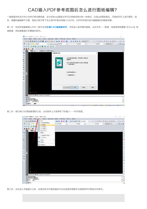
CAD插⼊PDF参考底图后怎么进⾏图纸编辑?
⼀般做相关的设计的⼩伙伴们肯定都知道,设计好的cad图纸⽂件可以转换成其它的⼀些格式,⽐如pdf图纸格式,可是在PDF上进⾏图形、线条、测量的编辑都不⽅便,现给⼤家分享下怎么将PDF按⽐例插⼊CAD内,以PDF的底印进⾏编辑操作的教程详解。
第⼀步:在你的电脑桌⾯上打开⼀款专业的迅捷CAD编辑器软件,然后进⼊软件操作⾯板,点击⽂件——新建,或者使⽤快捷键【Ctrl+n】快速新建,然后跟着提⽰步骤操作即可。
第⼆步:我们将CAD图纸新建好之后,点击软件上⽅菜单栏下的插⼊——PDF底图。
第三步:点击进⼊页⾯窗⼝之后,在弹出的⽂件储存路径中点击选择你想要作为底图的PDF图纸⽂件即可。
第四步:我们打开之后,点击图纸,会出⾏⼀个“+”字光栅图像参照,我们在图纸中选择⼀个基点,选择PDF底图的位置,单击⿏标左键完成,或者是在下⾯的命名框中输⼊RTPAN,按回车, 右键 或 Esc键完成。
第五步:我们将PDF底图调整好之后,就可以在软件的上⽅属性框中进⾏点击编辑图纸,进⾏操作了。
我们将图纸编辑好之后,记得点击⽂件下的另存为,设置好存储路径之后,点击确定就OK了,不光是可以将PDF图纸⽂件作为底图,其他的DGN、DWF图纸格式也是可以的,⽅法都⼀样,有兴趣的话,就⾃⼰去试⼀试吧。
W78E58中文
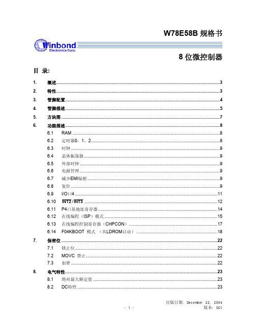
W78E58B规格书8位微控制器目录:1.概述 (3)2.特性 (3)3.管脚配置 (4)4.管脚描述 (5)5.方块图 (7)6.功能描述 (8)6.1 RAM (8)6.2 定时器0,1,2 (8)6.3 时钟 (9)6.4 晶体振荡器 (9)6.5 外部时钟 (9)6.6 电源管理 (9)6.7 减少EMI辐射 (9)6.8 复位 (9)6.9 I/O口4 (11)6.10 INT2/INT3 (12)6.11 P4口基地址寄存器 (14)6.12 在线编程(ISP)模式 (15)6.13 在线编程控制寄存器(CHPCON) (17)6.14 F04KBOOT 模式(从LDROM启动) (18)7.保密位 (22)7.1 锁止位 (22)禁止 (22)7.2 MOVC7.3 加密 (22)8.电气特性 (23)8.1 绝对最大额定值 (23)8.2 DC特性 (23)出版日期: December 22, 20048.3 AC特性 (25)8.3.1时钟输入波形 (25)8.3.2程序读取周期 (26)8.3.3数据读取周期 (26)8.3.4数据写周期 (27)8.3.5端口访问周期 (27)9.时序波形图 (28)9.1 程序读取周期 (28)9.2 数据读周期 (28)9.3 数据写周期 (29)9.4 端口访问周期 (29)10.典型应用电路 (30)10.1 扩展的外部程序存储器和石英晶体 (30)10.2 扩展的外部程序存储器和振荡器 (31)11.封装尺寸 (32)11.1 DIP40 (32)11.2 44 管脚PLCC (33)11.3 44 管脚PQFP (34)12.应用指南 (35)12.1 ISP 软件编程示例: (35)13.文件版本描述 (42)1. 概述W78E58B是具有带ISP功能的Flash EPROM的低功耗8位微控制器;ISP功能的Flash EPROM可用于固件升级。
SRD-1656D 16CH CIF 实时DVR用户手册说明书

SRD -1656D16CH CIF (1280H available) Real-time DVRKey FeaturesSRD-1656DDIsplay Video Inputs 16 Composite video 0.5-1 Vpp, 75 ohm automatic termination Resolution NTSC : 1280 x 480, 720 x 480 / PAL : 1280 x 576, 720 x 576liveFrame Rate NTSC : 480fps / PAL : 400fpsResolutionNTSC : 1280 x 480, 720 x 480 / PAL : 1280 x 576, 720 x 576Multi screen Display1 / 4 / 7 / 9 / 13 / 16 / 16A / Sequence / PIP peRFoRManCeoperating system embeddedLinux RecordingCompressionH.264Record RateNTSC : Up to 120fps@1280 x 480 / PAL : Up to 100fps@1280 x 576NTSC : Up to 120fps@704 x 480 / PAL : Up to 100fps@704 x 576NTSC : Up to 240fps@704 x 240 / PAL : Up to 200fps@704 x 288NTSC : Up to 480fps@352 x 240 / PAL : Up to 400fps@352 x 288ModeNTSC : Manual, Schedule (Continuous / Event), Event (Pre / Post), Time lapse (1~30 fps)PAL : Manual, Schedule (Continuous / Event), Event (Pre / Post), Time lapse (1 ~ 25fps)eventVideo loss, Motion (Level 1 ~ 10), Alarm, Tampering (Level 1 ~ 3)overwrite Modes Selectable (Stop / Continuous)pre-alarm Up to 30sec (5, 10, 20, 30sec)post-alarm Up to 6hour (5,10, 20, 30sec, 1, 3, 5, 10, 20min, 1, 2, 3, 4, 5, 6hour)search &playbacksearch ModeDate/Time, Event, Back up, POS, Motion (*All search include preview function)playback FunctionFast forward / backward (2x, 4x, 8x, 16x, 32x, 64x) *Backward play with i-frame only Slow forward / backward (1/2x, 1/4x, 1/8x)Step forward / backward *Backward play with i-frame onlynetwork (Ipv4)Transmission speed4CIF / 2CIF / CIF (NTSC : 120 / 240 / 480fps, PAL : 100 / 200 / 400fps)BandwidthUp to 32Mbps Bandwidth ControlSelectablestreamH.264 (4CIF / 2CIF / CIF selectable)Max. Remote Users Search 3 / Live unicast 10 / Live multicast 20protocol support TCP/IP , DHCP , PPPoE, SMTP , NTP , HTTP , HTTPS, DDNS, RTP , RTSP , SNMP Monitoring SmartViewer, Webviewer, SSM (CMS)smart phone platformAndroid, iOSprotocol supportRTP , RTSP , HTTP , CGI Max. Remote Users Live 2, Search 1storage Internal HDDUp to 4 SATA HDDsexternal (e-saTa Interface)2 External SATA ports (*Expansion bay, Model : SVS-5R/5E) DVD Writer (Back up)YesUsB (Back up)2 USB portsFile Format (Back up)BU (DVR player), EXE (Include player), AVI securitypassword protection1 Admin, 10 Group, 10 User per 1 group Data authenticationWatermark* The latest product information / specification can be found at • 16CH CIF real-time DVR• Up to 480(NTSC) / 400(PAL)fps recording rate • HDMI / VGA video output• 16CH audio inputs / 1CH audio output • Max. 4 internal HDDs• PTZ control via coaxial cable (Samsung CCVC, Pelco-C)• DVD-RW, Smart phone support (Android / iOS)• Accurate still image (De-Interlace support each channel)• Enhanced Network Bandwidth up to 32Mbps。
子宫内膜癌中PKD1的表达及其临床意义

子宫内膜癌中PKD1的表达及其临床意义赵彩琴;钮红丽【摘要】Purpose To investigate the expression of protein kinase D1 (PKD1) in endometrial carcinoma and normal endometrium,and to investigate its relationship with the clinicopathological features of endometrial carcinoma.Methods Immunohistochemical SP and qRT-PCR was used to detect the mRNA and protein expression of PKD1 in 92 cases of endometrial cancer and 48 cases of normal endometrium,and to analyze the relationship of expression of PKD1 with the tumor differentiation and clinical stage of endometrial carcinoma tissue.Western blot method was used to detect the expression level of PKD1 protein in normal endometrial cell line and endometrial carcinorna cell lines with different degree of differentiation.Results mRNA and protein expression of PKD1 in endometrial carcinoma tissues was significantly higher than those in normal endometrial tissues (P < 0.01),which showing a correlation to the degree of tissue differentiation and clinical pathologic staging.While,the expression level of PKD1 protein in endometrial cancer cell lines was also much higher than that in normal endometrial cells (P < 0.01),and the lower differentiation,the higher level of PKD1 proteinexpression.Conclusion PKD1 is highly expressed in endometrial cancer patients.The level of PKD1 expression may be an important reference for predicting the malignant degree of endometrial cancer.%目的探讨蛋白激酶D1(protein kinase D1,PKD1)在子宫内膜癌组织和正常子宫内膜组织中的表达,并分析其与子宫内膜癌临床病理特征的关系.方法应用免疫组化SP法及qRT-PCR法检测92例子宫内膜癌组织和48例正常子宫内膜组织中PKD1 mRNA及其蛋白的表达,分析PKD1在子宫内膜癌组织中的表达及其与分化程度、临床分期的关系.应用Westernblot法检测PKD1蛋白在正常子宫内膜细胞株及不同分化程度的子宫内膜癌细胞株中的表达水平.结果子宫内膜癌组织中的PKD1 mRNA及蛋白表达水平均显著高于正常子宫内膜组织(P<0.01);PKD1 mRNA及蛋白表达与子宫内膜癌的组织分化程度均有相关性,且组织分化程度越低,临床病理分期越高,PKD1的表达越丰富.PKD1蛋白在子宫内膜癌细胞株中的表达水平也远高于正常子宫内膜细胞中的表达(P<0.01),且癌细胞株的分化水平越低,PKD1蛋白表达的水平越高.结论PKD1在子宫内膜癌患者癌灶中呈高表达,PKD1表达水平的高、低可以做为预测子宫内膜癌恶性程度的一项重要参考依据.【期刊名称】《临床与实验病理学杂志》【年(卷),期】2017(033)001【总页数】4页(P8-11)【关键词】子宫肿瘤;子宫内膜癌;蛋白激酶D1;表达;病理诊断【作者】赵彩琴;钮红丽【作者单位】河南省南阳市第一人民医院生殖妇科 473000;河南省南阳市第一人民医院生殖妇科 473000【正文语种】中文【中图分类】R737.33子宫内膜癌是妇科常见的恶性肿瘤,其病死率高[1],发病机制目前尚不明确。
- 1、下载文档前请自行甄别文档内容的完整性,平台不提供额外的编辑、内容补充、找答案等附加服务。
- 2、"仅部分预览"的文档,不可在线预览部分如存在完整性等问题,可反馈申请退款(可完整预览的文档不适用该条件!)。
- 3、如文档侵犯您的权益,请联系客服反馈,我们会尽快为您处理(人工客服工作时间:9:00-18:30)。
ESC/POS 打印控制命令打印控制命令简表序号命令HEX 命令名称备注1 HT09 水平制表2 LF0A 打印并换行3 FF0C 页进纸4 CR0D 打印并回车,不走纸5 DLE EOT n10 04 n 实时状态传送6 DLE ENQ n10 05 n 实时响应主机请求7 ESC SP n1B 20 n 设置右边间距为 n 点8 ESC ! n1B 21 n 打印模式设置9 ESC * m n1 n2 d1~dn1B 2A …图形模式设定10 ESC 21B 32 选择缺省行距(1/6吋)11 ESC 3 n1B 33 n 行距设置为n/203吋12 ESC @1B 40 初始化13 ESC D d1~dn NUL1B 44 …水平制表位设置14 ESC J n1B 4A n 打印并进纸n/203吋15 ESC j n1B 6A n 打印并退纸n/203吋16 ESC a n1B 61 n 设置对齐方式17 ESC d n1B 64 n 打印并进纸n行18 ESC j n1B 70 n 驱动钱箱19 ESC S0 1B 0E 字符倍宽打印20 ESC DC4 1B 14 取消字符倍宽打印21 FS ! n1C 21 n 选择中文字体和打印模式22 FS &1C 26 进入汉字方式23 FS .1C 2E 退出汉字方式24FS S NL NR1C 53 n1 n2设置汉字左右间距25 GS !n 1D 21 n 设置字符大小26 GS ‘ n m 1D 27 n m 打印预设图形27 GS ( A pL pH n m1D 28 41 …执行测试打印28 GS ( F pL pH a m nL nH1D 28 46 …设置黑标定位偏移量29 GS * n1 n2 d1~dn1D 2A …定义下装点图30 GS / n1D 2F n 打印下装点图31 GS L nL nH1D 4C …设置打印区左边界32 GS V n m1D 56 n m 选择切纸方式及切纸送纸33 GS W nL nH1D 57 n m 设置打印区宽度34 GS a n1D 61 n 允许/禁止自动状态回复(ASB)35 GS r n1D 72 n 状态传送36 GS h n1D 68 n 设置条码高度37 GS k n m d1~dn1D 6B …打印条码38 GS V 0 xL xH yL Yh d1~dn1D 76 30 快速图形打印39 GS w n1D 77 n 设置条码水平尺寸2、命令详解RFT58 热敏打印控制板提供ESC/POS兼容打印命令、FS汉字打印命令。
各命令的描述形式如下:功能控制码格式:ASCII:以标准ASCII字符序列表示十进制:以十进制表示十六进制:以十六进制表示说明:该命令功能和使用说明。
2.1 水平制表HT格式:ASCII:HT 十进制:9 十六进制:09说明:(1)打印起始位转移到下一个水平制表位(2)在下一个水平制表位置已被设置后本命令才有效,否则被忽略。
水平制表位置用ESC D 设置。
(3)如果下一个水平制表位超出打印边界,则打印位置=打印区宽度+1,在这种情况下收到数据则立即执行“缓冲区满打印”并将打印起始位转移到下一行的最左边,收到的数据也被推移。
当收到行进纸命令如LF 则数据被打印,打印位置移到下一行的最左边。
2.2 打印并换行LF格式:ASCII:LF 十进制:10 十六进制:0A说明:打印行缓冲区里的内容并向前走纸一行。
当行缓冲器空时只向前走纸一行。
2.3 页进纸FF格式: ASCII: FF 十进制: 12 十六进制: 0C说明:黑标定位禁止时按已定义的页长进纸。
初始状态下,页长设置为约143 mm(44行);黑标定位允许时打印并走黑标纸到打印起始位置。
如果在带黑标打印纸的打印起始位置执行本命令,打印机将带黑标打印纸进纸到下一个打印起始位置。
2.4 打印并回车,不走纸CR格式:ASCII:CR 十进制:13 十六进制:0D说明:打印行缓冲区里的内容但不走纸。
2.5 实时状态传送DLE EOT n格式:ASCII:DLE EOT n 十进制:16 4 n 十六进制:10 04 n说明:实时状态传送1≤n≤4,返回信息b7=0,b4=1,b1=1,b0=0,其他位见下表位n=1 打印机状态n=2 离线状态n=3 错误状态n=4 纸传感器状态6 =1 FEED键被按下=0 FEED键未被按下=1 有错=0 无错=1有可自动恢复的错误=0无可自动恢复的错误=1 缺纸=0有纸5 =1 等待恢复在线 =0 无等待恢复在线=1 打印被缺纸中断 =0 无缺纸中断 =1 有无法恢复的错误 =0 无无法恢复的错误3 =1 离线 =0 在线 =1 有按FEED 进纸 =0 无按FEED 进纸 =1 有切刀错误 =0 无切刀错误 2=1 有打印头抬起 =0 无打印头抬起=1 有机械错误 =0 无机械错误=1 纸将尽 =0 非纸将尽关联命令:DLE ENQ2.6 实时响应主机请求 DLE ENQ n 格式: ASCII :DLE ENQ n 十进制: 16 5 n 十六进制: 10 05 n 说明:打印机响应主机的请求:n=1 从错误恢复并从错误出现的行开始重新开始打印; n=2 在清除接收和打印缓冲区后从错误恢复。
· 仅当自动切纸器错误,黑标检测错误或盖板打开错误出现时命令才有效。
· 命令不得插入多字节命令序列之间使用,否则不能正确响应 DLE ENQ 命令· 即使打印机处于脱机状态,打印缓冲区满或出现串行接口模式错误时,仍然执行该命令。
· DLE ENQ 2命令解除打印机故障状态,并清除已有的全部接收缓存区和打印机缓存器区内的内容,但存留ESC !ESC 3 等命令设置参数。
应用于打印机的可恢复故障的解除,不得用于打印头过温故障。
关联命令:DLE EOT2.7 设置字符右边间距为 n 点 ESC SP n格式: ASCII : ESC SP n 十进制 : 27 32 n 十六进制 : 1B 20 n说明: 设置字符右边间距为n 点(1点=0.125 mm )。
n=0~255。
示例:0:取消双倍高度1:设定双倍高度0:取消双倍宽度1:设定双倍宽度未定义2.9 图形模式设定ESC * m n1 n2 d1~dn格式:ASCII :ESC * m n1 n2 d1~dn 十进制:27 42 m n1 n2 d1~dn十六进制:1B 2A m n1 n2 d1~dn 说明:(1) 设定点图密度(m)和点数(n1,n2)并且定义点图数据。
打印点数m模式垂直方向(点数) 水平方向点数0 8点单密度8 68 DPI 101 DPI n2 x 256+n1 最多2881 8点双密度8 68 DPI 203 DPI n2 x 256+n1 最多57632 24点单密度24 203 DPI 101 DPI (n2 x 256+n1) x3 最多28833 24点双密度24 203 DPI 203 DPI (n2 x 256+n1) x3 最多576n1=0~255,n2=0~3。
(2) m用于选择点图方式。
(3) 水平方向点数为n1+256×n2。
(4) 如果点图数据超过一行,超过的部分被忽略。
(5) d为点图数据,相应位为1则表示一点,否则为零。
(n表示数据个数)(6) 在执行打印命令LF、CR 或ESC J 后,才会被打印出来,点图数据超过行宽时,超过部分将丢失,该命令允许字符和点阵图形同行混打。
2.10 选择缺省行距ESC 2 返回控制打印命令总表格式:ASCII :ESC 2 十进制:27 50 十六进制:1B 32说明:设置字符行间距为缺省值3.75mm(30×0.125mm)。
行间距包含字符高度。
2.11 行距设置命令ESC 3 n 设置行间距为n点行(n×0.125mm)返回控制打印命令总表格式:ASCII:ESC 3 n 十进制:27 51 n 十六进制:1B 33 n说明:(1)设置行间距为n点行。
n=0~255。
(2)每点距为1/203英寸,即该命令设置行间距为n×0.125mm,默认值为n=30。
2.12 初始化ESC @ 返回控制打印命令总表格式:ASCII:ESC @ 十进制:27 64 十六进制:1B 40说明:该命令初始化打印机下列内容:●清除打印缓冲区; ●恢复默认值; ●删除用户定义字符;2.13 水平制表位设置ESC D d1~dn NUL 返回控制打印命令总表格式:ASCII:ESC D d1~dn NUL十进制:27 68 d1~dn 00十六进制:1B 44 d1~dn 00说明:(1)d=1~255,n=1~32;(2)水平制表位设置为从打印区行首起的“d*字符宽度”;(3)在水平制表位设置后更改了字符宽度,已设置的水平制表位不变;(4)当用ESC D d1~dn NUL设置了水平制表位后,已设置的水平制表位取消;(5)水平制表位设置为d=8,执行HT命令后将下一个打印位置设置为第9列;(6)最多可以设置32个水平制表位,如果设置多于32个,在多余制表位的数据被认为是普通数据;(7)所有水平制表位可用ESC D NUL 命令予以取消;(8)打印机上电或复位时,水平制表位被设置为8个字符(初始状态所选的字符)。
2.14 打印并进纸n/203 吋ESC J n格式:ASCII:ESC J n 十进制:27 74 n 十六进制:1B 4A n说明:(1)打印行缓冲区里的内容,并向前走纸n点行(即n/203英寸)。
n=0~255。
(2)该命令只本行打印有效,不改变ESC 2,ESC 3命令设置的行间距值。
2.15 打印并退纸n/203 吋ESC j n格式:ASCII:ESC j n 十进制:27 106 n 十六进制:1B 6A n说明:(1)打印行缓冲区里的内容,并向后走纸n点行(即n/203英寸)。
n=0~255。
(2)该命令只本行打印有效,不改变ESC 2,ESC 3命令设置的行间距值。
2.16 设置对齐方式ESC a n格式:ASCII:ESC a n 十进制:27 97 n 十六进制:1B 61 n说明:n=0左对齐,n=1居中,n=2右对齐2.17 打印并进纸n 行ESC d n格式:ASCII:ESC d n 十进制:27 100 n 十六进制:1B 64 n说明:打印缓冲区内容并进纸n行(行距由ESC 2和ESC 3设定,缺省为30点=3.75mm)2.18格式:ASCII:ESC p m n1 n2 十进制:27 112 m n1 n2 十六进制:1B 70 m n1 n2说明:该命令用于根据n1,n2产生一定时间间隔的脉冲以控制钱箱动作。