Chapter 6 Electrical System
船舶电气英语

Company Logo
1.1 Electrical Hazards and Precaution
L 南o通g理工o学院
Marine electrical hazards:
L 南o通g理工o学院
18. insulation 绝缘 insulate 19. wire 电线 20. static 静态的 dynamic 21. navigational 航行的 22. accessory 附件 /ek’seseri/ 23. discharge 排放 24. capacity 容量 capacitor 25. cable 电缆 26. battery 电池 27. rotate 旋转 rotation 28. reciprocate 往复运动 29. motor 发动机 30. install 安装 31. extinguisher 灭火器 32. OBA-oxygen breathing apparatus 氧
Company Logo
教学目标与考核方式
L 南o通g理工o学院
教学目标:
1. 熟悉并掌握常用船舶电气 专业英语词汇发音及含义。
2. 快速,准确理解船舶电气 专业英语文献的含义。
3. 具备对普通船舶电气专业 英语文献的翻译能力。
考核方式:
平时成绩和期终考试相结 合。
教学目的
L 南o通g理工o学院
“船舶电气专业英语”,是一门应用性很强的基础课程。 它体现了船舶电气专业与英语的结合。是从事船舶电气行 业技术研究必须具备的一项技能。
阅读(Comprehension)
了解国际发展动态、进行先进性研究
学
习 目
口语(Oral)
的
6照明和信号系统-汽车电器设备(英文版)
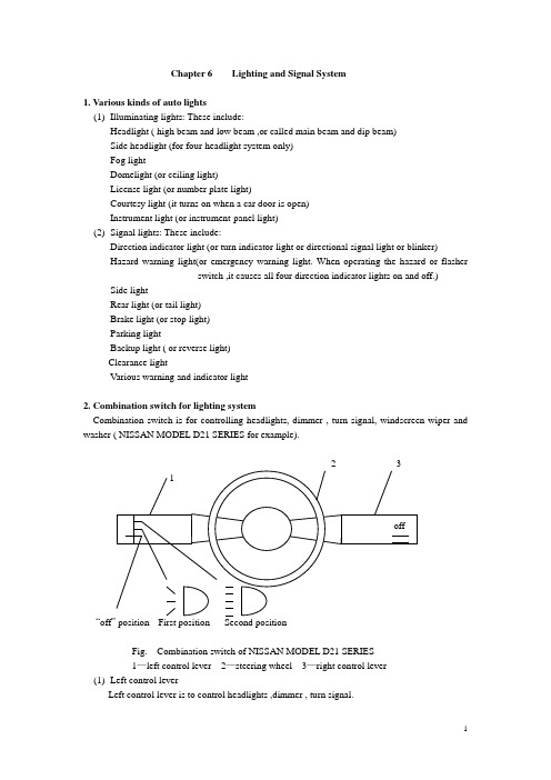
Chapter 6 Lighting and Signal System1. Various kinds of auto lights(1)Illuminating lights: These include:Headlight ( high beam and low beam ,or called main beam and dip beam)Side headlight (for four-headlight system only)Fog lightDomelight (or ceiling light)License light (or number plate light)Courtesy light (it turns on when a car door is open)Instrument light (or instrument-panel light)(2)Signal lights: These include:Direction indicator light (or turn indicator light or directional signal light or blinker)Hazard warning light(or emergency warning light. When operating the hazard or flasherswitch ,it causes all four direction indicator lights on and off.) Side lightRear light (or tail light)Brake light (or stop light)Parking lightBackup light ( or reverse light)Clearance lightVarious warning and indicator light2. Combination switch for lighting systemCombination switch is for controlling headlights, dimmer , turn signal, windscreen wiper and washer ( NISSAN MODEL D21 SERIES for example).“offFig. Combination switch of NISSAN MODEL D21 SERIES1—left control lever 2—steering wheel 3—right control lever(1)Left control leverLeft control lever is to control headlights ,dimmer , turn signal.●Lighting:Turn the switch to the first position: The side, tail, license plate and instrument panel lights will come on.Turn the switch to the second position: Headlights will come on and all the other lights remain on. To select the high beam, push the level forward. Pull it back to select the low beam.●Passing signal:Pulling the lever toward you will turn on the passing signal even when the headlight switch is “off”.●Turn signal:Move the lever up or down to signal to the turning direction. When the turn is completed, the turn signals cancel automatically.●Lane change signal:To indicate a lane change, move the lever up or down to the point where lights begin flashing.(2)Right control lever2—speed: “off”positionlow speed pull to washhigh speed2—speed with mist switch mist“off”positionlow speed pull to washhigh speed2—speed with intermittence “off”positionintermittentlow speed pull to washhigh speedTurn the ignition switch to “ACC” or “on” and move the lever down to operate the wiper.Move the lever up to wipe off a misty windscreen if this equipped. The wiper will operate only once.Pull the lever toward you to operate the washer.3. Relays and bulbs3.1 Relays(1)Function:Relays use a low control current to operate a solenoid, then the switch contacts can transmit very high working current.(2)Types of relaysThere are three basic types: normally-open (make)Normally-closed (break)Double-throw (changeover)88 86 85 88a 87 86 85 87a 87 86 85 88a 87aFig. Relays(3) Operation:A relay can be defined as an electromagnetic switch in which the contacts are actuated by asolenoid (an electromagnetic coil). The control current needed to operate the electromagnet is only 0.2 to 1 A, depending on the relay. However, the switch contacts can transmit very high working currents(up to 2000A for instance at the starting motor solenoid switch). It is advantageous to use a relay so that the high load between the electrical source and the consumer can be transmitted through a wire of generous cross-section and this can be kept short, whereas the control wire between the switch and the relay coil, which is subject to only very low loads, can be made as long as necessary.(3)Application:Relays are often used in horn, headlight, electric fuel pump, fog light and starting circuits.3.2 Light bulbs(1) Types of light bulbThere are two basic types according to the number of filament:Single-filament bulbDouble-filament bulbFor headlight bulbs, two types of common incandescent and halogen-wolfram bulbs can be of option.(3)Power selection of typical light bulbsBulb power should be selected according to the specifications. This is a example for Audi 100.Headlight 60 W/55 W (double filament for high beam and low beam,enclosed-type headlight)Side light 8 WStop light/tail light 21 W/5W (double filament)Direction indicator light 21 WReverse light 21 WLicense plate light 5 WFog light 55WParking light 4WDomelight 10WInstrument-panel light 2W4. Headlight4.1 Types of headlightThere two basic types of round and rectangular headlights according to the shape, and two types of semi-enclosed and enclosed (or vacuum) headlights according to the construction.The rectangular type has become increasingly popular in recent years. They fit the tapered front-end style of the modern cars.4.2 Headlight circuit:A typical headlight circuit is as shown below.dipswitchhigh beam leftlow beam lefthigh beam indicatorhigh beam rightlow beam rightside leftrear leftinstrument panelside rightrear rightlicense plate4.3 OperationRefer to the combination switch (left control lever).4.4 Headlight aimingAiming adjustment is made by turning screws in a spring-loaded holder. Top screw is for up-and-down adjustment. Side screw is for left-to-right adjustment.2Round type rectangular type1—Horizontal aim adjusting screw 2—Vertical aim adjusting screw4.5 Inspecting headlight circuitAccording to the different wiring circuit, checking procedures are different. Generally follow below.●Use public fuse: One bulb is not working. Check bulb or connection.Two or more bulbs are not working. Check fuse and switch.●Use separate fuse: One bulb is not working. Check fuse and bulbTwo or more bulbs are not working. Check switch or relay.5. Stop light (or brake light)Stoplight often uses double-filament bulbs, sharing with tail light. This is similar to those used in the headlights. The stop light must be brighter than tail light so that it can be seen in daylight.5.1 Stop light circuit:A typical stop light circuit is as shown below.5.2 OperationWhen depressing brake pedal, the stop light switch closes. Stop lights come on.5.3 Types of stop light switchThere are two basic types.Mechanical attached to brake pedalAttached to operating mechanismPressure-activated hydraulicPneumatic (for air pressure braking system)contactsspringterminalmechanical type pressure-activated typeFig. Schematic view5.4 Inspecting stop light circuit●One bulb is not working: check bulb or connection.●Two bulbs are not working: check fuse, then stop light switch. For checking stop lightswitch, you can directly connect two terminals and pinpoint whether the switch isoperative or not.6. Backup light (or reverse light)The backup lights come on when the shift lever is moved to“R”position. At the same time, the reverse alert device sounds.6.1 Backup light circuitA typical backup light circuit is as shown below.reverse lightFig. Simplified backup light circuit6.2 OperationWhen shifting into reverse, reverse switch is closed. Reverse light comes on. Meanwhile, current flows through horn and it sounds. At the same time, current also flows through coil L1 and coil L2. As two magnetic field directions are opposite, the resultant magnetic force is poor. Relay contacts remain closed. After the capacitor is charged, current and magnetic field in coil L2 disappears. The resultant field is strong enough to open the relay contacts. Horn stops sounding. Then the capacitor discharges through two coils. This resultant field keeps contacts still open until it discharges fully. Then relay contacts close again and horn resumes sounding. This cycle repeats while the reverse light switch is closed.6.3 Inspecting backup light circuit:●One bulb is not working: check the bulb or connection.●Two bulbs are not working: if it sounds, check the circuit.If it doesn’t sound, check fuse and switch.●Bulbs are on, but no sound: check the reverse alert device. (procedure: horn, contacts,capacitor, coils)7. Direction indicator lightThis is often called the flasher circuit. In this circuit, a flasher relay makes and breaks the current flow between 60 to 120 times every minute, so producing a flashing light.7.1 Direction indicator light circuitA typical direction indicator light circuit is as shown below.Front leftRear leftFig. Simplified direction indicator light circuit7.2 Types of flasher and operationThere are three types of flasher.(1)Hot wire type: It uses resistance wire. When current flows, it expends and contracts as itheats up or cools down, to operate contacts.(2)Capacitor type: It uses capacitor, charging and discharging. This activates the two coils tooperate the contacts. (Refer to backup light)(3)Electronic type: It uses capacitor, charging and discharging. This activates the triodes tooperate the circuit.When moving up or down the direction indicator switch, the flasher works and intermittently allows the current to flow. This will makes and breaks the right or left direction indicator light circuit to give a turn signal.7.3 Inspecting direction indicator light circuit●If one bulb is not working, check the bulb or connection.●If one-side bulbs are not working, check indicator switch.●If all bulbs are not working, check fuse, ignition switch, flasher unit.●If no flashing or kept on, check flasher unit.8. Electric hornMost horns are of the vibrating diaphragm type. To get a melodious sound, cars are often equipped with two horns of different tones. So it better to use horn relay to pass high current.8.1 Horn circuitA typical horn circuit is as shown below.8.2 OperationWhen depressing the horn button, horn relay is activated. Magnetic coil makes contact points close. Current flows from battery to horns through horn relay. The horns sound.8.3 Inspecting horn circuit●One horn loses sound: check horn or connection. Tune up horn if necessary.●Two horns lose sound: check fuse, horn button switch and relay.●Horn sound is low: check battery condition, relay contact points condition, and tune uphorns if necessary.8.4 Horn adjustment:●Tone adjustment: adjust the gap between iron core and iron armature in the horn.●Volume adjustment: adjust the pressure of contacts inside the horn by adjusting screw.9. Optical fiber lightingIn many cars, the instrument panel requires lights at many places to illuminate the speedometer, the indicating gauges, and the various controls. Because of the small spaces available, it becomes a problem to locate light bulbs where they are needed. To eliminate this problem, some cars use fiber-optic conductors. Theses conductors are made up of a very large number of extremely fine and flexible threads, or fibers , of pure glass which are bound together into a bundle, or cord. Each fiber has the property of being able to conduct light, even around bends or corners. As light starts down the fiber, it is reflected off the outer surface of the fiber. If the fiber is curved, the light keeps bouncing off the outer surfaces with little loss. By the time the light comes out the other end of the fiber, it is almost as strong as when it entered.Now, to utilize this effect, fiber bundles(each with many fibers) are run from a central light source to the various outlets on the instrument panel where light is needed. Therefore, only one light bulb is needed to provide light at many places. Installation and servicing problems are made easier to solve by the use of the fiber bundles. Only one light bulb needs to be replaced if a burnout occurs, the fiber bundles can be bent almost any way without damaging them.。
民航英语词汇

民航英语词汇部门: xxx时间: xxx整理范文,仅供参考,可下载自行编辑英语专业词汇1. adjective 形容词2. adverb 副词3. pronoun 代词4. numeral 数词5. preposition 介词6. conjunction 连词7. interjection 感叹词8. prefix v..给…加前缀 n. 前缀9. suffix v.给…加后缀 n. 后缀10. morpheme 词素11. article n.<物品)一件,一种文章,论文12. autobiography 自传13. bracket n. ⑴括号⑵<年龄,收入等的)等级段,档次v. ⑴把…置于括号内⑵把…归入同一类b5E2RGbCAP14. chapter n.<书,文章的)章,回15. dub v.⑴给…起绰号,把…称为⑵为<电影等)配音,译制<影片)16. essay n. 散文,随笔17. fiction 小说18. grammar n. 语法<书)19. idiomatic adj. 符合习惯用法的,习俗的20. literacy n. 识字,有文化,读写能力21. literally adv. ⑴逐字地,照原文,照字面地⑵真正地22. literary adj. ⑴文学上的⑵文人的,书卷气的23. literature n. ⑴文学,文学作品⑵文献,图书资料24. masterpiece n.杰作25. motto n. ⑴箴言,格言,座右铭⑵<尤指英国圣诞节小鞭炮中彩色纸上印的)俏皮话,妙句⑶题词,题句,警句p1EanqFDPw26. phrase n.乐句,短语27. prose n. 散文28. punctuation n.标点,标点符号29. sonnet n. 十四行诗30. tale n.故事,传说31. aboriginal n. 土著 adj. 土著的32. archaeology n. 考古学33. Bible n. 圣经,有权威的书34. bishop n. ⑴主教⑵<国际象棋中的)象35. blessing n. 祝福36. Buddhist n. 佛教37. Buddhist n. 佛教经38. cathedral n. 大教堂39. catholic adj. ⑴天主教的⑵普遍的,广泛的。
汽车工程专业英语
Chapter 1 Automotive Basics(1) Today s average car contains more than 15,000 separate, individual parts that must work together. These parts can be grouped into four majorcategories: body, engine, chassis and electrical equipment 。
当今的车辆一般都由15000多个分散、独立且相互配合的零部件组成。
这些零部件主要分为四类:车身、发动机、底盘和电气设备。
1.1 Body(车身)(2) The body is designed to keep passengers safe and comfortable. Thebody styling provides an attractive, colorful, modern appearance for the vehicle.车身的设计要保证乘客安全舒适。
车身的款式使得汽车看起来漂亮迷人、色彩斑斓、时尚前卫。
1.2 Engine(发动机)(3)The internal combustion engine is most common: this obtains its powerby burning a liquid fuel inside the engine cylinder. There are two typesof engine: gasoline and diesel . Both engines are called heat engines; the burning fuel generates heat which causes the gas inside the cylinder to increase its pressure and supply power to rotate a shaft connected to the transmission .内燃机是最常见的,其动力来自气缸里液体燃料的燃烧。
电磁兼容技术——chapter 6
Introduction to Electromagnetic CompatibilitySecond EditionCLAYTON R.PAULDepartment of Electrical and Computer Engineering,School of Engineering, Mercer University,Macon,Georgia and Emeritus Professor of Electrical Engineering,University of Kentucky,Lexington,KentuckyA JOHN WILEY&SONS,INC.PUBLICATIONChapter6Conducted Emissions and Susceptibility(401/1013)6.1MEASUREMENT OF CONDUCTED EMSSIONSThe FCC and CISPR22set limits on conducted emissions extend from150kHz to 30MHz(see Fig.2.178p/1013p).It is important to understand the measurement procedure that is used to verity compliance with the conducted emission regulatory limits.A LISN(line impedance stabilization network)is inserted between the commercial power outlet and product’s ac power cord when emission is measured for verification of compliance with the regulatory limit above.FIGURE6.1Scheme of measurement of conducted emissions(402p/1013p)The purpose of the conducted emission test is to measure the noise current that exit the product’s ac power cord conductors.A spectrum analyzer is attached to the LISN and measures the conducted emissions of the product.6.1.1The Line Impedance Stabilization Network(LISN)The noise currents(emissions)could be simply measured with a current probe. However,the requirement that the measured data be co-relatable between measurement sits may render this simple test unrealistic.The impedance seen looking into the ac power system wall outlets varies considerably over the measurement frequency range and from outlet to outlet and building to building.This variability in the loading presented to the product affects the amount of noise that is conducted out the power cord.In order to make this consistent between test sits,the impedance seen by the product looking out the product’s ac power cord must be stabilized from the measurement site to measurement site.This is the first objective of the LISN---to present a constant impedance to the product’s power cord outlet over the frequency range of the conducted emission test.The amount of noise that is present on the power system net varies form site to sit.This“external”noise enters the product’s ac power cord,and,unless it is somehow excluded,will add the measured conducted emissions.It is desired to measure only those conducted emissions that are due to the product.This gives the second objective of the LISN---to block conducted emissions that are not due to the product being tested so that only the conducted emissions of the product are measured.The two objective of the LISN:1.To present a constant impedance(50Ω)between the phase conductor andthe safety wire(the“green wire”)and between the neutral conductor and the safety wire;2.To prevent external conducted noise on the power system net formcontaminating the measurement;These two objectives are to be satisfied only over the frequency range of the conducted emission test(150kHz–30MHz).Another unstated requirement for the LISN is that it be able to pass the60Hz(50 Hz)power required for operation of the product.FIGURE6.2Illustration of the LISN(404p/1013p)The function of components:1.The purpose of the two1µF capacitors are to divert“external noise”ofthe commercial power net(Wall outlet)and prevent that noise fromflowing through the measurement device and contaminating the testdata.2.The two50µH inductors can block the external noise.3.The two0.1µF capacitors have the function of preventing any dc fromoverloading the input of the test receiver.4.One50Ωresistor is the input impedance of the spectrum analyzer,whilethe other is a50Ωdummy load that insures that the impedance betweenphase and the safety wire and between neutral and the safety wire andthe safety wire is approximately50Ωat all times.5.The1kΩresistors act as static charge paths to discharge the0.1µFcapacitors in the event that the50Ωresistors are removed.It is instructive to compute the impedances of these elements from150kHz to 30MHz of FCC regulatory limit.Element Z150kHz(Ω)Z30MHz(Ω)50µH47.19424.80.1µF10.610.0531µF 1.060.0053The load impedance of the product under test varies around50Ωslightly from 150kHz to30MHz of FCC regulatory limit.The load impedance of the commercial power system is almost short-circuited inthe point view of the noise from150kHz to30MHz of FCC regulatory limit.So we get the equivalent circuit of the LISN as seen by the product over the conducted emission regulatory frequency range,as the figure below shows.FIGURE6.3Equivalent circuit of the LISN as seen by the product over the conducted emission regulatory frequency range.(405p/1013p)At the60Hz power frequency the50µH inductors have impedances of18.8mΩ, the0.1µF capacitors have impedances of26.5kΩ,and the1µF capacitors have impedances of2.7kΩ.Thus at the60Hz power frequency the LISN has virtually no effect,and ac power for functional operation is provided to the product.The measured voltages,denoted by V P(^above the V omitted)and V N(^above the V omitted),are measured between the phase wire and the safety wire and between the neutral wire and the safety wire.Now we see why the conducted emission limits are specified in terms of voltages when,in fact,we are interested in conducted emission current.The phase current I P and the neutral current I N are related to the measured voltage byWhere we have assumed that the capacitors of the LISN are short circuits and the inductors are open circuits over the frequency range of the measurement,as FIGURE6.3(405p/1013p)shows.Representing the LISN as50Ωresistors between phase wire and green wire andbetween neutral wire and green wire as in FIGURE6.3(the ideal behavior of the LISN over the frequency change conducted emission regulatory limit)simplifies the analysis of conducted emissions.The voltages that are to be measured for verification of compliance to the regulatory limit are the voltages across these50Ωresistors,and are denoted as V P and V N(^above the V omitted).These voltages are related to the emission current via Ohm’s law according to (6.1).We may decompose these current into a differential-mode component that flows out through the phase conductor and returns on the neutral conductor,and a common-mode component that flows out through the phase and neutral conductors and returns on the green wire as shown in FIGURE6.4:FIGURE6.4Illustration of the contributions of differential-mode andcommon-mode current components on the measured conducted emissions. (406p/1013p)Solving these givesThe measured voltages areIt is important to understand that,common-mode currents can be of the order of or exceed differential-mode currents in conducted emissions.It is also important to remember that differential-mode currents for conducted emission regulatory compliance are not the functional60Hz power line currents.Observe that the differential-mode current flows down through on50Ωand up through the other,whereas the common-mode currents flow down through both 50Ωresistors.Therefore the contributions due to each current add in V P and subtract in V N.If the common and differential mode currents are of the same magnitude,the phase and neutral voltages will no be the same.Generally,one component dominates the other so that the magnitudes of the phase and neutral voltages are about the same:orVirtually all products contain a power supply filter as the last circuit that noise currents pass through before the exit the product through the power core and then pass through the LISN.Power supply filters contain components that are intended to reduce either differential-mode or common-mode currents.The decomposition of the total currents into common-mode anddifferential-mode components along with this realization that each element of the power supply filter affects one and only one of these components is the key to designing power supply filters that are effective in the reduction of conducted emissions so that the product will comply with the regulatory limits.Two common methods of blocking the common-mode current path are shown in FIGURE6.5.FIGURE6.5Methods of reducing the common-mode contribution to conducted emissions:(a)a green-wire inductor;(b)a two-wire product.In many electronic products an inductor is placed in the green wire,where it enters the product as shown in FIGURE6.5a.This tends to present a high impedance to the common-mode currents that are in the frequency range of the conducted emission regulatory limit,yet a path for fault currents to flow still exists that preserves the shock hazard protection of the green wire.For safety reasons it is undesirable to physically solder(焊接)an inductor in the green wire,because the solder joint may become defective,opening the safety wire path and leaving a potential shock hazard.In order to prevent this from happening,the inductor is constructed by winding several turns of the green wire around a ferrite toroid(that has suitable characteristics over the conducted emission limit frequency range).Typical values of this green-wire inductance are of order0.5mH,which has an impedance of some471Ωat150kHz.One might expect that this impedance would increase at30MHz,but this is not necessarily true.Parasitic capacitances between the windings of the toroid will typically cause its performance to deteriorate at the higher frequencies,as was discussed in Chapter5.Another technique for blocking the common-mode path is to construct atwo-wire product.The power cord contains only the phase and the neutral wires, and the safety wire is absent.There is a60Hz transformer at the power entrance of the product,as shown in FIGURE6.5b,to make the impedance of thecommon-mode path larger.6.2Power Supply FiltersThere are virtually no electronic products today can comply with the conducted emission regulatory requirements without the use of some form of power supply filter being inserted where the power cord exits the product.6.2.1Basic Properties of FiltersThere is a wealth of design information available for the filters used in communications,signal processing,and automatic controls.We should be cautioned that power supply filters that are intended to reduce conducted emissions are rarely designed using these traditional filter designs.In order to master the power filter in depth,we had better review some basic principles of traditional filters that are common to all filters.Filters are typically characterized by their insertion loss(IL,插入损耗),which is typically stated in dB.The FIGURE6.6(410p/1013p)shows the definition of the IL.FIGURE6.6How to calculate the ILConsider the problem of supplying a signal to a load as shown in FIGURE6.6a.A filter is inserted between the source and the load in order to prevent certain frequency components of the source from reaching the load,as shown in FIGURE6.6b.V L,wo(with a caret^)is the load voltage without the filter;V L,w(with a caret^), the load voltage with the filter inserted.The IL is defined asNote that the voltages in this expression are not denoted with a caret(^),and are therefore are the magnitudes of the voltages.The insertion loss gives the reduction in the load voltage at the frequency of interest due to the insertion of the filter.Typically,the insertion loss is displayed as a function of frequency.FIGURE6.7shows some simple filters.FIGURE6.7Four simple filters:band reject,high pass,band pass,and low pass (Ask students to match a,b,c,and d with the names above)--------Example:to determine the IL of FIGURE6.7a.The load voltage without the filter can be easily determined from FIGURE6.7a asThe load voltage with the filter inserted isThe insert loss is the ratio of(6.8)and(6.9):τis the time constant of the circuit.A plot of the insertion loss would show0dB from dc to the3dB point ofω3dB=1/τand an increase at a rate of20dB/decade above that.Therefore the lowpass filter passed frequency components at frequencies below that.For frequencies above the3dB point the insertion loss expression simplified toOther filters are analyzed in a similar road map.--------The example above has illustrated an important point:The insertion loss of a particular filter depends on the source and load(R s and R L)impedances,and therefore cannot be stated independently of the termination impedances.Most filter manufacturers provide frequency response of the insertion loss of aparticular filter.Please bear in mind the test condition:R s=R L=50Ω.The load impedance corresponds to the50Ωof the LISN between phase and green wire and between neutral and green wire.Source impedance is seen looking back into the product’s power input terminals. It is doubtful that this will be50Ωand furthermore that it will be constant over the frequency range of the conducted emission test(150kHz~30MHz)!So use of the manufacturer’s insertion loss data to assess the performance of the filter in a product may not give realistic results in a typical application. Furthermore there are two currents that must be reduced:common-mode and differential-mode.FIGURE6.8(413p/1013p)shows how to measure the IL in the common or differential-mode.FIGURE6.8IL testsIn differential-mode test,the phase and neutral form the circuit to be tested,and the green wires are left unconnected,as shown in FIGURE6.8a.In common-mode test,the phase and neutral wires are tied together and form the test circuit with the green wire,as shown in FIGURE6.8b.6.2.2A Generic Power Supply Filter TopologyThe most common power supply filter topology is some version of the genericfilter topology shown if FIGURE6.9(413p/1013p).FIGURE6.9A typical power supply filter topologyThe filter topology resembles aπstructure.I D and I C(both with^)are the differential-and common-mode currents at the output of the product(usually the input to the product’s power supply) respectively.I’D and I’C(both with^),differential-and common-mode currents at the input to de LISN(at the output of the filter)respectively.The object of the filter is to reduce the unprimed current levels(I D and I C both with^)to the primed levels such that the primed currents(I’D and I’C both with^) give measured voltagesWhich are below the conducted emission limit at all frequency range of the limit such as150kHz~30MHz.6.2.3Effect of Filter Elements on Common-and Differential-mode Currents Keep referring to the Fig.6.9.A green-wire inductor L GW is included in the green wire between the filter output and the LISN input to block common-mode currents as discussed above.Capacitors between phase and neutral wires,C DL and C DR,are included to divert differential-mode currents.These are referred to as line-to-line capacitors. Capacitors that have insulation properties approved by safety agencies and are suitable for use as line-to-line capacitors are referred to as“X-caps.”The subscripts L and R denote“left”and“right”with regard to the side of the filter on which they are placed.The typical value of C DL≈0.047µF.Capacitors C CL and C CR are included between phase and green wire and between neutral and green wire to divert common-mode currents.These are referred to as line-to-ground capacitors.Capacitors that have insulation properties approved by safety agencies and are suitable for use as line-to-ground capacitors are referred to as“Y-caps.”The typical value of C C≈2200pF.The reason that different capacitors are needed for these tasks is due to safety considerations.For example,suppose that one of the line-to-ground Y-caps(such as C CL)shorts out.If this capacitor happens to be connected to the phase wire,120V(in USA) will be tied to the green wire,which is usually tied directly to the product frame, presenting an obvious shock hazard.Also,the safety agencies such as the Underwriters Laboratory(UL)in the United States specify the maximum leakage current that may flow through the line-to-ground capacitors at60Hz in order to minimize shock hazards due to these leakage currents(to keep nice insulation state between phase and neutral line).This provides an important constraint on the maximum value of the line-to-ground capacitors that may be used in the filter.Observe that the line-to-ground capacitors on the left,C CL,are in parallel with the 50Ωresistors of the LISN.Therefore,if their impedances at the frequency of interest are not significantly lower than50Ω,and then these capacitors will be ineffective in diverting the common-mode current.To judge whether the line-to-ground capacitors on the left will be effective,let us compute their impedance for typical values of C CL≈2200pF.The impedances of these capacitors will equal50Ωat1.45MHz,and so the capacitors C CL will be effective in diverting common-mode currents from the LISN50Ωresistors only above this frequency!One final element is typically included—the common-mode choke represented by the coupled inductors.The self-inductances of each winding are represented by L and the mutual inductance is represented by M.Typically this element consists of two identical windings on a common ferrite core(that has suitablecharacteristics over the conducted emission frequency range),and so is similar to a transformer,as shown in Fig.6.10a.FIGURE6.10Use of a common-mode choke to block common-mode conducted emissions:(a)physical construction and equivalent circuit;(b)equivalent circuit for differential-mode currents;(c)equivalent circuit for common-mode currents.Because the windings are identical and are wound tightly on the same core,the mutual inductance is approximately equal to the self-inductance,L=M.The purpose of the common-mode choke is to block common-mode currents. Ideally,the common-mode choke does not affect differential-mode currents.T he 60Hz fl flux ux cancels in the core and does not saturate it.This was shown in Chapter5,but it is worthwhile to repeat that here.6.2.4Separation of the Conducted Emissions into Common-andDifferential-Mode Currents for Diagnostic PurposesThe preceding discussion of the power supply filter concentrated on the ideal behavior of the filter.If the line-to-line capacitors behave ideally,then little differential-mode current will reach the LISN.If we can obtain sufficiently large values for the common-mode choke inductance,the line-to-ground capacitors, and the green-wire inductor,then very little common-mode current will reach the LISN.In practice this almost never occurs,and the product may still fail to comply with the conducted emission regulatory limit even though a careful design of the filter has been completed.When the product is tested for compliance and found to be out of compliance at certain frequencies in the frequency range of the regulatory limit,the next question is how we shall e ffectively and efficiently diagnose and correct the problem and bring the conducted emissions into compliance.In order to illustrate the necessity for this,it is worthwhile to point out that this author has spent many needless hours changing values of the filter components and observing no change in the levels of the conducted emissions.Product development schedules cannot tolerate this inefficiency in the correction of the problem.We must be able to quickly and correctly diagnose the root of the problem. Which element of the power supply filter needs to be changed,and what should the element’s new value be?There are other ways of reducing the levels of the conducted emissions that will be discussed in Section6.3,but attacking the power supply filter is a viable first step.The most important point to realize in the course of changing a power supply element value to effect a reduction in the conducted emissions is illustrated in Fig.6.13.We have shown a typical plot of the total current of the phase or neutral wire.This is decomposed into common-and differential-mode components.Although rather obvious,it is important to point out that the total current is the sum or difference of the common-mode and differential-mode components as shown by(6.2):If one component is larger than the other component,the total current is the dominant component!This seemingly obvious statement illustrates that one component may dominate over certain frequency ranges.If we change the power supply filter so as to reduce the dominant component, we will reduce the total current.On the other hand,if we change the power supply filter so as to reduce the component that is not dominant,we will cause no reduction in the total!Therefore,if we wish to reduce the total conducted emission at a particular frequency,we must reduce the dominant component at that frequency.It is also important to observe that one component may be dominant over one frequency range yet not be dominant over another portion of the conducted emission frequency range.FIGURE6.13Illustration of the important observation that one component of current may dominate the other over a particular frequency range of the conducted emission test.In order to reduce the total conducted emission,the dominant component must be reduced.Now let us consider how we shall reduce a particular component.We saw previously that each element of the power supply filter usually affects only one component;either differential-or common-mode.(The line-to-ground capacitors appear in the differential-mode circuit,yet they are usually much smaller than the line-to-line capacitors that are in parallel with them,and as such do not affect the differential-mode current.However,if the line-to-line capacitor with which they are in parallel is absent,then they will affect the differential-mode current.)So,if we need to reduce the level of a particular(dominant)component,we mustlter element that affects that component. change the value of a power supply fi filterFor example,suppose that the common-mode component dominates the differential-mode component at a frequency where the conducted emission exceeds the regulatory limit.Increasing the value of the line-to-line capacitance will only reduce the differential-mode component,and so will not reduce the total conducted emission,since the differential-mode component was not the dominant component at this frequency.Conversely,suppose that the differential-mode component dominates the common-mode component at a particular frequency where the conducted emission exceeds the regulatory limit.Increasing the green-wire inductance by placing more turns on the core may reduce the common-mode component,but will not affect a change in the conducted emissions at this frequency,since the differential-mode component was dominant.These observations easily explain the author’s experience that a radical change inlter may cause absolutely nothe value of an element of the power supply fi filterchange in the total conducted emissions;the component that was not dominant was reduced.If we are to be able to rapidly and correctly bring about a reduction in the conducted emissions by changing the values of some elements of the power supply filter,we must know which component is the dominant component in the total conducted emission.We need a diagnostic tool that can separate the total conducted emission into its common-and differential-mode components at each frequency of the regulatory limit.The schematic of the device(diagnostic tool)is shown in Fig.6.14and a photograph is shown in Fig.6.15.FIGURE6.14Schematic of a device to separate the common-mode and differential-mode conducted emission contributions.FIGURE6.15Photograph of the device of Fig.6.14.The device basically adds or subtracts the phase and neutral voltages of the LISNto give only the differential-mode or only the common-mode component of the total conducted emission.It makes use of two wideband transformers.The phase and neutral output voltages of the LISN are applied to the primaries of the transformers.The secondaries are connected in series,and a switch changes the polarity of theneutral voltage.We will consider an experiment to demonstrate the effectiveness of the deviceand to confirm the observations above about the effect of the individual elements of the power supply filter.A typical digital device containing a switching power supply and a powersupply filter was tested.The elements of the power supply fi filter lter were fi first rst removed,and the product product’’s conducted emissions were measured.These data are shown in Fig.6.16.Observe that the conducted emissions exceed the FCC Class B limit by over 30dB!The device was inserted at the output of the LISN,and the components are also shown in Fig.6.16.Observe that the common-and differential-mode components of the total emission as measured with the device are the same order of magnitude.FIGURE 6.16Measured conducted emissions of a typical digital product separated into differential-and common-mode components with no power supply filter.---------------Table 2.1FCC and CISPR Conducted Emission Limits for Class B Digital Devices (76p/1013p)---------------lter elements were next added one by one and their effect observed.The fi filterFirst,3300pF line-to-ground capacitors were added.The results are shown in Fig.6.17.Note that the addition of the line-to-ground capacitors has reduced both the common-and differential-mode components by the same amount,but only above approximately2MHz.The3300pF line-to-ground capacitors are effectively in parallel with the50-V resistors of the LISN(see Figs.6.11and6.12),and so give a break frequency of order1MHz where their impedance equals50V.Thus they will begin to shunt both common-and differential-mode currents above this frequency.FIGURE6.17Measured conducted emissions of a typical digital product separated into differential-and common-mode components with3300-pFline-to-ground capacitors added.Next we add a0.1-mF line-to-line capacitor.The results are shown in Fig.6.18. Note that the common-mode component is unchanged,yet the differential-mode component has been reduced considerably.This is sensible to expect,since this capacitor should affect only the differential-mode component(see Fig.6.12).FIGURE6.18Measured conducted emissions of a typical digital product separated into differential-and common-mode components with a0.1-mFline-to-line capacitor added.Next we add the1-mH green-wire inductor.The results are shown in Fig.6.19. Observe that the differential-mode components are unchanged,but the common-mode components have been substantially reduced.FIGURE6.19Measured conducted emissions of a typical digital product separated into differential-and common-mode components with a green-wire inductor added.6.3P ower S uppliesThe primary source of conducted emissions is generally the power supply of the product.There are numerous points within a power supply that generate noise measured by the LISN.Each particular type of power supply has unique noise-generating properties.Any power supply filter is capable of reducing the conducted emissions only to a certain degree.The most effective method for reducing conducted emissions is to suppress them at their source.This should be attempted where possible.But the noise can be reduced at its source only to a certain degree and still retain the functional performance of the supply.Pulses with sharp rise/fall times have high-frequency spectral content.Some power supplies such as switched-mode power supplies(switchers)rely on fast-rise/fall time pulses to operate and to reduce power losses in the supply.These types of noise sources can be reduced only to a certain point,so that compromises must be made between retaining the desired functional performance and reduction of the noise source.It is worthwhile to consider the purpose of the product’s power supply.The purpose of power supply is converting120V/220V,60Hz/50Hz commercial ac power to the dc voltage levels required by the product. Maintaining his output voltage within certain bounds regardless of the changing load on the power supply as the product performs its required function is an important function of a power supply,and is referred to as regulation.。
Chapter 6 Test 8 A 2005

Chapter 6 Test 8 A 2005/11 Class ___________ Name _____________ No. ______ Mark _________Vocabulary___vacuum cleaner______2. Y ou can drive to work in this. ______________________3. Y ou can keep food cool and fresh in this. ______________________4. Y ou can do mathematical sums on this. _______________________5. Y ou can cook food very quickly in this. ______________________6. Y ou can listen to programmes on this. _______________________7. Y ou can watch programmes on this. ______________________8. Y ou can use this to wash your clothes. ______________________9. Y ou can cook a slice of bread in this . ______________________10. Y ou can keep food frozen in this. ______________________ II. Complete each sentence using the correct word from each box. Use each word only once:1. A _______pilot______ is someone who _______flies_______ aeroplanes.2. A ______________ is someone who ______________ computers.3. An ________________ is someone who _______________ buildings.4. An ________________ is someone who _______________ new things.5. An _____________ is someone who ____________ into space in a rocket.6. An ____________ is someone who _____________ electrical appliances.7. A _____________ is someone who _____________ films.8. A _____________ is someone who _____________ photographs.GrammarI. Rewrite these sentences in the future tense1. The bus arrived at eight o’clock. __The bus will arrive at eight o’clock.2. I didn’t see them. ________________________________3. My parents left on Tuesday. ________________________________4. We weren’t in time for the film. ________________________________5. Charles came to see me on Sunday. _______________________________6. They missed the ferry. _________________________________ II. Change these future sentences into either positive or negative statements, or questions, as shown:1. They’ll sell the house. [-] __ They won’t sell the house._____2. I won’t buy a newspaper today. [+] _____________________________3. Paul won’t come with us. [?] ______________________________4. He’ll meet me later. [-] ______________________________5. They won’t be late. [-] ______________________________6. Will the plane leave on time? [+] ______________________________ III. Y ou and a friend are going shopping. Complete the questions with the words in brackets and then complete the answers:1.__Shall we take __ the car or the bus ? (we, take) _ W e’ll take__ the car.2.____________ with us ? (Daniel, come) No, _________ with us.3.Where ___________ the car ? (you, park) I ___________ in the car park.4.Where _______________ ? (we, do the shopping) _________ in the mall.5.__________________? (shopping mall, busy) No, ________________.6.What else _______________ ? (we, do) _________________ lunch. IV. Correct the following sentences. Be careful! One of them doesn’t need correcting:1.What time you’ll be home tonight?_____________________________________________________________ 2.When will the others arrive ?_____________________________________________________________ 3.I won’t can come to the party._____________________________________________________________ 4.David won’t to leave work until six._____________________________________________________________ 5.Will be you ready by lunchtime ?_____________________________________________________________ 6.Jane will be not here next week._____________________________________________________________ 7.Will we can go to West Town later ?_____________________________________________________________ 8.We can’t to go out this afternoon._____________________________________________________________ V. Complete these sentences with at, on or in. Be careful! Three sentences are already correct:1.James will be at work _________ Monday morning.2.The others will be here ___________ lunchtime.3.Will you be able to see me ___________ next Thursday ?4.Susan will arrive _______________ the morning.5.I’ll ring you ____________ three o’clock.6.I’ll ring you _______________ a few minutes.7.The manager will contact you _________ this afternoon.8.We’ll come ______________ Friday.9.The students will be here __________ half past two.10.I’ll post this letter _____________ tomorrow.VI. Fill in the gaps with words from the box to complete the schedule:We’ll catch the plane (1)____ eight o’clock (2) ______ Monday morning. We’ll land (3) ______ Japan at (4) ______ . We’ll take a bus (5) ______ the airport (6) _____ the hotel. We’ll have lunch in the hotel restaurant. After some shopping (7) ________ the afternoon, we’ll go back to the hotel (8) _______ the evening. We (9) ________ get up early (10) ________ Tuesday. We’ll stay in bed (11) _______ half-past nine. But (12) ______ Tuesday afternoon (13) ________ visit the museum. (14) ______ Wednesday we’ll have a packed lunch, and we’ll (15) ________ the whole day (16) ________ Tokyo. (17) _______ evening we’ll watch a film. Thursday will be our last day (18) ________ Japan. We (19) _________ be (20) _______ the airport by eleven o’clock.VII. Complete these questions and answers:1. ___Is___ Paul ____going to ____ visit Julie? No, ______he isn’t.___2. ______ you __________ go for a swim ? Y es, I _________.3. _______ Simon ___________ book the tickets ? Y es, he _________.4. ________ they ___________ help us ? No, _______________.5. ________ your sister ___________ get the food ? No, __________.6._________ Charles and Eddie __________ come ? Y es, ___________.7. _________ Doris _________ do any painting ? No, ____________.8. ________ your brothers _________ come with us ? Y es, ___________.。
Electrical system(民航飞机电气系统1).

Secondary source.
• A secondary source is equipment that transforms and/or converts primary source power to supply electrical power to either AC or DC powered equipment.
17
Primary (Main) Power Source
18
Primary Power Source
A primary source is equipment that generates electrical power from energy other than electrical, and is independent of any other electrical source.
30
Classification of electrical load
• Vital (critical, emergency) • EssentiLeabharlann l • Non-essential
• The primary purpose of igniting the fuel/air mixture is still the domain of the magneto. However, the demand for electrical energy in the airplane has increased tremendously.
11
DEFINITIONS OF AIRCRAFT ELECTRICAL SYSTEM
12
Electrical System
An electrical system consists of an electrical power source, its power distribution system and the electrical load connected to that system.
ATA章节中英对照

Chapter 1 –Brief History of AviationChapter 2 –DeregulationChapter 3 –Structure of the IndustryChapter 4 –Airline EconomicsChapter 5 –How Aircraft FlyChapter 6 –SafetyChapter 7 –SecurityChapter 8 –AirportsChapter 9 –Air Traffic ControlChapter 10 –Airlines and the Environment5章时间限制、维修检查(Time Limits,Maint. Checks) 6章尺寸和区域(Dimensions and Access Panels)7章顶起和支撑(Lifting and Shoring)8章对准和称重(Leveling and Weighing)9章飞机拖曳(Towing and Taxiing)10章飞机停场,系留,封存(Parking,Mooring,Storage) 11章标牌和铭记(Placards and Markings)12章勤务(Servicing)20章标准施工---机体(Standard Practices---Airframe) 21章空调(Air Conditioning)22章自动飞行(Auto Flight)23章通讯(Communications)24章电源(Electrical Power)25章设备/装饰(Equipment/Furnishings)26章 .防火(Fire Protection)27章飞行操纵(Flight Controls)28章燃油(Fuel)29章液压源(Hydraulic Power)30章防冰和排雨(Ice and Rain Protection)31章指示/记录系统(Indicating/Recording system)32章起落架(Landing Gear)33章灯光(Lights)34章导航(Navigation)35章氧气(Oxygen)36章气源(Pneumatic)37章真空(Vacuum)38章水/污水(Water/waste)45章中央维护系统(Central maintenance System)49章机载辅助动力装置(Airborne Auxiliary Power)51章结构与标准施工(Structures & Standard Practices) 52章舱门(Doors)53章机身(Fuselage)54章发动机吊舱/吊架(Nacelles/Pylons)55章稳定装置 (Stabilizers)安定面56章窗户(Windows)57章机翼(Wings)70章标准施工—发动机(Standard Practices—Engines)71章动力装置(Power Plant( Package))72章发动机(内部)(Engine (Internals))73章发动机燃油和控制(Engine Fuel and Control)74章点火装置(Ignition)75章发动机空气(Air)76章发动机操纵(Engine Controls)77章发动机指示(Engine Indicating)78章排气系统(Exhaust)79章发动机滑油系统(Oil)80章发动机起动(Starting)82章注水(Water Injecting)91章图表(不同性质的)(Charts (Miscellaneous))01 INTRODUCTION05 PERIODIC INSPECTIONS06 DIMENSIONS AND AREAS07 LIFTING AND SHORING08 LEVELING AND WEIGHING09 TOWING AND TAXIING10 PARKING, MOORING, STORAGE AND RETURN TO SERVICE11 PLACARDS AND MARKINGS12 SERVICING - ROUTINE MAINTENANCE18 VIBRATION AND NOISE ANALYSIS (HELICOPTER ONLY)20 STANDARD PRACTICES - AIRFRAME21 AIR CONDITIONING22 AUTO FLIGHT23 COMMUNICATIONS24 ELECTRICAL POWER25 EQUIPMENT / FURNISHINGS26 FIRE PROTECTION27 FLIGHT CONTROLS28 FUEL29 HYDRAULIC POWER30 ICE AND RAIN PROTECTION31 INDICATING / RECORDING SYSTEMS32 LANDING GEAR33 LIGHTS34 NAVIGATION35 OXYGEN36 PNEUMATIC37 VACUUM38 WATER / WASTE39 ELECTRICAL - ELECTRONIC PANELS AND MULTIPURPOSE COMPONENTS 41 WATER BALLAST45 CENTRAL MAINTENANCE SYSTEM (CMS)46 INFORMATION SYSTEMS49 AIRBORNE AUXILIARY POWER51 STANDARD PRACTICES AND STRUCTURES - GENERAL52 DOORS53 FUSELAGE54 NACELLES / PYLONS55 STABILIZERS56 WINDOWS57 WINGS60 STANDARD PRACTICES - PROPELLER / ROTOR61 PROPELLERS / PROPULSORS62 MAIN ROTOR(S)63 MAIN ROTOR DRIVE(S)64 TAIL ROTOR65 TAIL ROTOR DRIVE66 ROTOR BLADE AND TAIL PYLON FOLDING67 ROTORS FLIGHT CONTROL70 STANDARD PRACTICES - ENGINE71 POWER PLANT - GENERAL72 ENGINE72(T) ENGINE - TURBINE / TURBOPROP, DUCTED FAN / UNDUCTED FAN72(R) ENGINE - RECIPROCATING73 ENGINE - FUEL AND CONTROL74 IGNITION75 BLEED AIR76 ENGINE CONTROLS77 ENGINE INDICATING78 EXHAUST79 OIL80 STARTING81 TURBINES (RECIPROCATING ENGINES)82 WATER INJECTION83 ACCESSORY GEAR BOXES (ENGINE DRIVEN)84 PROPULSION AUGMENTATION91 CHARTS5章时间限制、维修检查(Time Limits,Maint. Checks)6章尺寸和区域(Dimensions and Access Panels)7章顶起和支撑(Lifting and Shoring)8章对准和称重(Leveling and Weighing)9章飞机拖曳(Towing and Taxiing)10章飞机停场,系留,封存(Parking,Mooring,Storage)11章标牌和铭记(Placards and Markings)12章勤务(Servicing)BMS3-33润滑脂的介绍/posts/35/topic-0045-359438.html20章标准施工---机体(Standard Practices---Airframe)21章空调(Air Conditioning)空调出口温度高/posts/35/topic-0045-359394.html[原创]关于737-300/500的空调/posts/35/topic-0045-356247.htmlPACK空中超温,会有那些原因引起呢?(专业贴)/posts/35/topic-0045 -359163.html22章自动飞行(Auto Flight)737NG的Y/D故障分析供大家参考/posts/72/topic-0045-729542.html 23章通讯(Communications)24章电源(Electrical Power)IDG和GEN /posts/35/topic-0045-358102.html737-300 B2972电源及APU自动关车排故思路之分析/posts/182/topic-0 045-1827865.html25章设备/装饰(Equipment/Furnishings)26章防火(Fire Protection)有关737灭火瓶...... /posts/35/topic-0045-357937.htmlAPU火警探测/posts/35/topic-0045-357662.html27章飞行操纵(Flight Controls)28章燃油(Fuel)737飞机燃油浮子电门/posts/35/topic-0045-359544.html29章液压源(Hydraulic Power)液压问题/posts/35/topic-0045-359382.html关于液压保险在液压管路的作用和位置?请教/posts/35/topic-0045-3592 99.html液压系统故障/posts/35/topic-0045-359411.html30章防冰和排雨(Ice and Rain Protection)31章指示/记录系统(Indicating/Recording system)32章起落架(Landing Gear)如何延长飞机轮胎的使用寿命/posts/35/topic-0045-358979.html前轮磨损/posts/35/topic-0045-359232.html谁能说说金属刹车片和碳刹车片的优缺点?/posts/35/topic-0045-358669. html请问哪位对防滞刹车结构熟悉的,简单介绍一下,谢谢那里有资料,网上有吗?http://bbs. /posts/35/topic-0045-359091.html请教:飞机换轮子的时候为什么要转动轮子? /posts/177/topic-0045-177 5484.html一起B737-300飞机使用自动速度刹车时,AUTO SPEED BRAKE 跳开关跳开http://bbs.fee /posts/103/topic-0045-1038900.html33章灯光(Lights)34章导航(Navigation)35章氧气(Oxygen)36章气源(Pneumatic)一起引气故障导致的增压故障(B737NG)/posts/103/topic-0045-1035067. html37章真空(Vacuum)38章水/污水(Water/waste)45章中央维护系统(Central maintenance System)49章机载辅助动力装置(Airborne Auxiliary Power)APU启动不起来了! /posts/35/topic-0045-357370.htmlAPU维护灯亮/posts/35/topic-0045-357331.html51章结构与标准施工(Structures & Standard Practices)52章舱门(Doors)53章机身(Fuselage)54章发动机短舱/吊架(Nacelles/Pylons)55章稳定装置(Stabilizers)56章窗户(windows)[讨论]玻璃上裂纹深度的测量??/posts/35/topic-0045-350765.html57章机翼(wings)70章标准施工---发动机(Standard Practices---Engines)71章动力装置(Power Plant (Package))IAEV2500系列发动机试车总结/posts/85/topic-0045-850361.html72章发动机(内部)(Engine (Internals))73章发动机燃油和控制(Engine Fuel and Control)74章点火装置(Ignition)75章发动机空气(Air)76章发动机操纵(Engine Controls)77章发动机指示(Engine Indicating)78章排气系统(Exhaust)737反推故障/posts/35/topic-0045-357397.html79章发动机滑油系统(Oil)80章发动机起动(Starting)82章注水(Water Injecting)91章图表(不同性质的)(Charts (Miscellaneous))ATA Specification 22001 *Reserved for Airline Use2 *Reserved for Airline Use3 *Reserved for Airline Use4 *Reserved for Airline Use5 TIME LIMITS/ MAINTENANCE CHECKS-00 General-10 Time Limits-20 Scheduled Maintenance Checks-30 & -40 Reserved-50 Unscheduled Maintenance checks6 DIMENSIONS AND AREAS7 LIFTING & SHORING-00 General-10 Jacking-20 Shoring8 LEVELING & WEIGHING-00 General-10 Weighing and Balancing-20 Leveling9 TOWING & TAXIING-00 General-10 Towing-20 Taxiing10 PARKING, MOORING, STORAGE & RETURN TO SERVICE -00 General-10 Parking/Storage-20 Mooring-30 Return to Service11 PLACARDS AND MARKINGS-00 General-10 Exterior Color Schemes and Markings-20 Exterior Placards and Markings-30 Interior Placards12 SERVICING-00 General-10 Replenishing-20 Scheduled Servicing-30 Unscheduled Servicing13 *Unassigned14 *Unassigned15 *Unassigned16 *Unassigned17 *Unassigned18 VIBRATION AND NOISE ANALYSIS (HELICOPTER ONLY) -00 GENERAL --10 VIBRATION ANALYSIS-20 NOISE ANALYSIS19 *Unassigned20 STANDARD PRACTICES-AIRFRAME-90 *Reserved for Airline Use21 AIR CONDITIONING-00 General-10 Compression-20 Distribution-30 Pressurization Control-40 Heating-50 Cooling-60 Temperature Control-70 Moisture/Air Contaminant22 AUTO FLIGHT-00 General-10 Autopilot-20 Speed-Attitude Correction-30 Auto Throttle-40 System Monitor-50 Aerodynamic Load Alleviating23 COMMUNICATIONS-00 General-10 Speech Communications-15 SATCOM-20 Data Transmission and Automatic Calling -30 Comfort-40 Interphone-50 Audio Integrating-60 Static Discharging-70 Audio & Video Monitoring-80 Integrated Automatic24 ELECTRICAL POWER-00 General-10 Generator Drive-20 AC Generation-30 DC Generation-40 External Power-50 AC Electrical Load Distribution-60 DC Electrical Load Distribution25 EQUIPMENT/FURNISHINGS-00 General-10 Flight Compartment-20 Passenger Compartment-30 Galley-40 Lavatories-50 Additional Compartments-60 Emergency-70 Available-80 Insulation26 FIRE PROTECTION-00 General-10 Detection-20 Extinguishing-30 Explosion Suppression27 FLIGHT CONTROLS-00 General-10 Aileron & Tab-20 Rudder & Tab-30 Elevator & Tab-40 Horizontal Stabilizer-50 Flaps-60 Spoiler, Drag Devices and Variable Aerodynamic Fairings -70 Gust Lock & Dampener-80 Lift Augmenting28 FUEL-00 General-10 Storage-20 Distribution-30 Dump-40 Indicating29 HYDRAULIC POWER-00 General-10 Main-20 Auxiliary-30 Indicating30 ICE AND RAIN PROTECTION-00 General-10 Airfoil-20 Air Intakes-30 Pitot and Static-40 Windows, Windshields and Doors-50 Antennas and Radomes-60 Propellers/Rotors-70 Water Lines-80 Detection31 INDICATING/RECORDING SYSTEMS-00 General-10 Instrument & Control Panels-20 Independent Instruments-30 Recorders-40 Central Computers-50 Central Warning Systems-60 Central Display Systems-70 Automatic Data Reporting Systems 32 LANDING GEAR-00 General-10 Main Gear and Doors-20 Nose Gear and Doors-30 Extension and Retraction-40 Wheels and Brakes-50 Steering-60 Position and Warning-70 Supplementary Gear33 LIGHTS-00 General-10 Flight Compartment-20 Passenger Compartment-30 Cargo and Service Compartments -40 Exterior-50 Emergency Lighting34 NAVIGATION-00 General-10 Flight Environment-20 Attitude & Direction-30 Landing and Taxiing Aids-40 Independent Position Determining -50 Dependent Position Determining -60 Flight Management Computing35 OXYGEN-00 General-10 Crew-20 Passenger-20 Passenger-30 Portable36 PNEUMATIC-00 General-10 Distribution-20 Indicating37 VACUUM-00 General-10 Distribution-20 Indicating38 WATER/WASTE-00 General-10 Potable-20 Wash-30 Waste Disposal-40 Air Supply39 *Unassigned40 *Unassigned41 WATER BALLAST-00 General-10 Storage-20 Dump-30 Indication42 *Unassigned43 *Unassigned44 CABIN SYSTEMS-00 General-10 Cabin Core System-20 Inflight Entertainment System-30 External Communication System-40 Cabin Mass Memory System-50 Cabin Monitoring System-60 Miscellaneous Cabin System45 CENTRAL MAINTENANCE SYSTEM-00 General-5 thru -19 CMS/Aircraft General-20 thru -49 CMS/Airframe Systems-45 Central Maintenance System-50 thru -59 CMS/Structures-60 thru -69 CMS/Propellers-70 thru -89 CMS/Power Plant45INFORMATION SYSTEMS-00 General-10 Airplane General Information Systems -20 Flight Deck Information Systems-30 Maintenance Information Systems-40 Passenger Cabin Information Systems -50 Miscellaneous Information Systems47 *Unassigned48 *Unassigned49 AIRBORNE AUXILIARY POWER-00 General-10 Power Plant-20 Engine-30 Engine Fuel and Control-40 Ignition/Starting-50 Air-60 Engine Controls .-70 Indicating-80 Exhaust-90 Oil50 Cargo and Accessory Compartments-00 General-10 Cargo Compartments-20 Cargo Loading Systems-30 Cargo Related Systems-40 Available-50 Accessory-60 Insulation51 Standard Practices, General-00 General-10 Investigation, Cleanup and Aerodynamic Smoothness-20 Processes-30 Materials-40 Fasteners-50 Support of Airplane for Repair and Alignment Check Procedures -60 Control-Surface Balancing-70 Repairs-80 Electrical Bonding52 DOORS-00 General-10 Passenger/Crew-20 Emergency Exit-30 Cargo-40 Service and Miscellaneous-50 Fixed Interior-60 Entrance Stairs-70 Monitoring and Operation-80 Landing Gear53 FUSELAGE-00 General-10 thru -90 (As Required) Fuselage Sections54 NACELLES/PYLONS-00 General-10 thru -40 (As Required) Nacelle Section-50 thru -80 (As Required) Pylon55 STABILIZERS-00 General-10 Horizontal Stabilizer or Canard-20 Elevator-30 Vertical Stabilizer-40 Rudder56 WINDOWS-00 General-10 Flight Compartment-20 Passenger Compartment-30 Door-40 Inspection and Observation57 WINGS-00 General-10 Center Wing-20 Outer Wing-30 Wing Tip-40 Leading Edge and Leading Edge Devices -50 Trailing Edge Trailing Edge Devices -60 Ailerons and Elevons-70 Spoilers-80 (as required)-90 Wing Folding System58 *Unassigned59 *Reserved for Airline Use60 STANDARD PRACTICES - PROPELLER/ROTOR61 PROPELLERS/PROPULSION-00 General-10 Propeller Assembly-20 Controlling-30 Braking-40 Indicating-50 Propulsor Duct62 ROTOR(S)-00 General-10 Rotor blades-20 Rotor head(s)-30 Rotor Shaft(s)/Swashplate Assy(ies) -4063 ROTOR DRIVE(S)-00 General-10 Engine/Gearbox couplings-20 Gearbox(es)-30 Mounts, attachments-40 Indicating64 TAIL ROTOR-00 General-10* Rotor blades-20* Rotor head-30 Available-40 Indicating65 TAIL ROTOR DRIVE-00 General-10 Shafts-20 Gearboxes-30 Available-40 Indicating66 FOLDING BLADES/PYLON-00 General-10 Rotor blades-20 Tail pylon-30 Controls and Indicating67 ROTORS FLIGHT CONTROL-00 General-10 Rotor-20 Anti-torque Rotor control (Yaw control)-30 Servo-control System68 *Unassigned69*Unassigned70 STANDARD PRACTICES - ENGINES71 POWER PLANT-00 General-10 Cowling-30 Fireseals-40 Attach Fittings-50 Electrical Harness-60 Air Intakes-70 Engine Drains72 ENGINE TURBINE/TURBO PROP DUCTED FAN/UNDUCTED FAN-00 General-10 Reduction Gear, Shaft Section (Turbo-Prop and/or Front Mounted Gear Driven Propulsor)-20 Air Inlet Section-30 Compressor Section-40 Combustion Section-50 Turbine Section-60 Accessory Drives-70 By-pass Section-80 Propulsor Section (Rear Mounted)73 ENGINE FUEL AND CONTROL-00 General-10 Distribution-20 Controlling-30 Indicating74 IGNITION-00 General-10 Electrical Power-20 Distribution-30 Switching75 AIR-00 General-10 Engine Anti-Icing-20 Cooling-30 Compressor Control-40 Indicating76 ENGINE CONTROLS-00 General-10 Power Control-20 Emergency Shutdown77 ENGINE INDICATING-00 General-10 Power-20 Temperature-30 Analyzers That-40 Integrated Engine Instrument Systems 78 EXHAUST-00 General-10 Collector/Nozzle-20 Noise Suppressor-30 Thrust Reverser-40 Supplementary Air79 OIL-00 General-10 Storage-20 Distribution-30 Indicating80 STARTING-00 General-10 Cranking81 TURBINES-00 General-10 Power Recovery-20 Turbo-Supercharger82 WATER INJECTION-00 General-10 Storage-20 Distribution-30 Dumping and Purging-40 Indicating83 ACCESSORY GEAR-BOXES-00 General-10 Drive Shaft Section-20 Gearbox Section84 Propulsion Augmentation-00 General-10 Jet Assist Takeoff85 *Unassigned86 *Unassigned87 *Unassigned88 *Unassigned89 *Unassigned90 *Unassigned91 CHARTS92 *Unassigned93 *Unassigned94 *Unassigned95 *Reserved for Airline Use96 *Reserved for Airline Use97 WIRING REPORTING-00-00 General-01-00 Zone 100 Fuselage Lower-02-00 Zone 200 Fuselage Top-03-00 Zone 300 Stabilizers-04-00 Zone 400 Nacelles-Pylons-05-00 Zone 500 Left Wing-06-00 Zone 600 Right Wing-07-00 Zone 700 Landing Gear Compartment -08-00 Zone 800 Doors-09-00 Zone 900 Lavatories & Galleys-20-00 Electrical Standard Items/Practices -21-00 Air Conditioning - General-21-10 Compression-21-20 Distribution-21-30 Pressurization Control-21-40 Heating-21-50 Cooling-21-60 Temperature Control-21-70 Moisture/Air Contaminant Control-22-00 Auto Flight - General-22-10 Autopilot-22-20 Speed - Attitude Correction-22-30 Auto Throttle-22-40 System Monitors-22-50 Aerodynamic Load Alleviating-23-00 Communications - General-23-10 Speech Communications-23-15 SATCOM-23-20 Data Transmission and Automatic Calling-23-30 Passenger Address, Entertainment and Comfort-23-40 Interphone-23-50 Audio Integrating-23-60 Static Discharging-23-70 Audio and Video Monitoring-23-80 Integrated Automatic Tuning-24-00 Electrical Power - General-24-10 Generator Drive-24-20 AC Generation-24-30 DC Generation-24-40 External Power-24-50 AC Electrical Load Distribution-24-60 DC Electrical Load Distribution-25-00 Equipment/Furnishings - General-25-10 Flight Compartment-25-20 Passenger Compartment-25-30 Galley-25-40 Lavatories-25-60 Emergency-25-80 Insulation-26-00 Fire Protection - General-26-10 Detection-26-20 Extinguishing-26-30 Explosion Suppression-27-00 Flight Controls - General-27-10 Aileron & Tab-27-20 Rudder & Tab-27-30 Elevator & Tab-27-40 Horizontal Stabilizer-27-50 Flaps-27-60 Spoiler, Drag Devices and Variable Aerodynamic Fairings -27-70 Gust Lock & Dampener-27-80 Lift Augmenting-28-00 Fuel - General-28-10 Storage-28-20 Distribution-28-30 Dump-28-40 Indicating-29-00 Hydraulic Power - General-29-10 Main-29-20 Auxiliary-29-30 Indicating-30-00 Ice and Rain Protection - General-30-10 Airfoil-30-20 Air Intakes-30-30 Pitot and Static-30-40 Windows, Windshields and Doors-30-50 Antennas And Radomes-30-60 Propellers/Rotors-30-70 Water Lines-30-80 Detection-31-00 Indicating/Recording Systems - General -31-10 Instrument and Control Panels-31-20 Independent Instruments-31-30 Recorders-31-40 Central Computers-31-50 Central Warning Systems-31-60 Central Display Systems-31-70 Automatic Data Reporting Systems-32-00 Landing Gear- General-32-10 Main Gear and Doors-32-20 Nose Gear and Doors-32-30 Extension and Retraction-32-40 Wheels and Brakes-32-50 Steering-32-60 Position And Warning-32-70 Supplementary Gear-33-00 Lights - General-33-10 Flight Compartment-33-20 Passenger Compartment-33-30 Cargo and Service Compartments-33-40 Exterior-33-50 Emergency Lighting-34-00 Navigation - General-34-10 Flight Environment Data-34-20 Attitude & Direction-34-30 Landing and Taxiing Aids-34-40 Independent Position Determining-34-50 Dependent Position Determining-34-60 Flight Management Computing-35-00 Oxygen - General-35-10 Crew-35-20 Passenger-35-30 Portable-36-00 Pneumatic - General-36-10 Distribution-36-20 Indicating-37-00 Vacuum - General-37-10 Distribution-37-20 Indicating-38-00 Water/Waste - General-38-10 Potable-38-20 Wash-38-30 Waste Disposal-38-40 Air Supply-44-00 Cabin Systems - General-44-10 Cabin Core System-44-20 In-flight Entertainment System-44-30 External Communication System-44-40 Cabin Mass Memory System-44-50 Cabin Monitoring System-44-60 Miscellaneous Cabin System-45-00 Central Maintenance System (CMS) General -45-05 CMS/Aircraft General-45-20 CMS/Airframe Systems-45-45 Central Maintenance System-45-50 CMS/Structures-45-60 CMS/Propellers-45-70 CMS/Power Plant-46-00 Information Systems - General-46-10 Airplane General Information Systems-46-20 Flight Deck Information Systems-46-30 Maintenance Information Systems-46-40 Passenger Cabin Information Systems-46-50 Miscellaneous Information Systems-49-00 Airborne Auxiliary Power - General-49-10 Power Plant-49-20 Engine-49-30 Engine Fuel And Control-49-40 Ignition And Starting-49-50 Air-49-60 Engine Controls-49-70 Indicating-49-80 Exhaust-49-90 Oil-50-00 Cargo And Accessory Compartments General -50-10 Cargo Compartments-50-20 Cargo Loading Systems-50-30 Cargo Related Systems-50-40 Available-50-50 Accessory Compartments-50-60 Insulation-52-00 Doors - General-52-10 Passenger/Crew-52-20 Emergency Exit-52-30 Cargo-52-40 Service-52-50 Fixed Interior-52-60 Entrance Stairs-52-70 Door Warning-52-80 Landing Gear-53-00 Fuselage - General-54-00 Nacelles/Pylons - General-54-10 Nacelle Section-54-50 Pylon-55-00 Stabilizers - General-55-10 Horizontal Stabilizer or Canard-55-20 Elevator-55-30 Vertical Stabilizer-55-40 Rudder-56-00 Windows - General-56-10 Flight Compartment-56-20 Passenger Compartment-56-30 Door-56-40 Inspection and Observation-57-00 Wings - General-57-10 Center Wing-57-20 Outer Wing-57-30 Wing Tip-57-40 Leading Edge and Leading Edge Devices-57-50 Trailing Edge and Trailing Edge Devices -57-60 Ailerons-57-70 Spoilers-57-90 Wing Folding System-61-00 Propellers/Propulsors - General-61-10 Propeller Assembly-61-20 Controlling-61-30 Braking-61-40 Indicating-61-50 Propulsor Duct-62-00 Rotors-63-00 Rotor Drives-64-00 Tail Rotor-65-00 Tail Rotor Drive-66-00 Folding Blades/Pylon-67-00 Rotors Flight Control-71-00 Power Plant - General-71-10 Cowling-71-20 Mounts-71-30 Fire seals-71-40 Attach Fittings-71-50 Electrical Harness-71-60 Air Intakes-71-70 Engine Drains-72-00 Engine Turbine/Turbo Prop Ducted Fan/Unducted Fan-72-10 Reduction Gear, Shaft Section (Turbo-Prop and/or Front Mounted GearDriven Propulsor)-72-20 Air Inlet Section-72-30 Compressor Section-72-40 Combustion Section-72-50 Turbine Section-72-60 Accessory Drives-72-70 By-pass Section-72-80 Propulsor Section (Rear Mounted)-73-00 Engine Fuel And Control - General-73-10 Distribution-73-20 Controlling-73-30 Indicating-74-00 Ignition - General-74-10 Electrical Power Supply-74-20 Distribution-74-30 Switching-75-00 Air - General-75-10 Engine Anti-Icing-75-20 Cooling-75-30 Compressor Control-75-40 Indicating-76-00 Engine Controls - General-76-10 Power Control-76-20 Emergency Shutdown-77-00 Engine Indicating - General-77-10 Power-77-20 Temperature-77-30 Analyzers-77-40 Integrated Engine Instrument Systems -78-00 Exhaust - General-78-10 Collector/Nozzle-78-20 Noise Suppressor-78-30 Thrust Reverser-78-40 Supplementary Air-79-00 Oil - General-79-10 Storage-79-30 Indicating-80-00 Starting - General-80-10 Cranking98 *Reserved for Airline Use99 *Unassigned100 *Do not use101 *Do not use102 *Do not use103 *Do not use104 *Do not use105 *Do not use106 *Do not use107 *Do not use108 *Do not use109 *Do not use110 *Do not use111 *Do not use112 *Do not use113 *Do not use114 *Do not use115 Flight Simulator Systems。
- 1、下载文档前请自行甄别文档内容的完整性,平台不提供额外的编辑、内容补充、找答案等附加服务。
- 2、"仅部分预览"的文档,不可在线预览部分如存在完整性等问题,可反馈申请退款(可完整预览的文档不适用该条件!)。
- 3、如文档侵犯您的权益,请联系客服反馈,我们会尽快为您处理(人工客服工作时间:9:00-18:30)。
SEA
CHAPTER 6 ELECTRICAL SYSTEM
Question 9: List the main parts of Coil Ignition System.
SEA
CHAPTER 6 ELECTRICAL SYSTEM
蓄电池用于储存电能,它将电能转变为化学 能储存,在用电时再将化学能转变为电能。
SEA
CHAPTER 6 ELECTRICAL SYSTEM
Question 2: List the types of Battery.
Electrolyte inlet 电解液插入端
Dilute H2SO4 稀 Negative plate
CHAPTER 6 ELECTRICAL SYSTEM
Question 1: List the major parts of a car electrical system.
Battery
Starter
Alternator Ignition Lighting Auxiliary
Electronic Device
导体在磁场中移动会产生电流,反之电也可以产生 磁。保持导体固定不动,移动磁场,导体中就会产 生电流,该电流称为感应电流。交流发电机的基本 原理就是这样的,通过机电装置把机械能转变为电 能。
SEA
CHAPTER 6 ELECTRICAL SYSTEM
4) The starter must crank the engine at a specified minimum speed (starting speed) in order to generate the air-fuel mixture necessary for self-sustained operation of spark-ignition engines, even under adverse conditions, and must support the engine as it runs up to minimum self-sustained speed after initial ignition. Electric motors (DC, AC and three-phase), as well as hydraulic and pneumatic motors are used as starting motors for internalcombustion engines.
Electronic Electronic
Mechanical
Determining the ignition angle on the basis of the Mechanical speed and load condition of the engine High-tension generation Distribution and assignment of the ignition spark to the correct cylinder Power section
蓄电池电流流过线圈时,铁芯成为强磁铁。铁芯的磁 力推动柱塞,推杆同柱塞一端接触,柱塞的运动使推 杆向外移动,从而推杆移动小齿轮与飞轮齿圈啮合。 电磁线圈利用磁力移动推杆使两齿轮接合。
SEA
CHAPTER 6 ELECTRICAL SYSTEM
6) The solenoid also does another important job. There is a contact disc on the other end of the plunger. When current flows through the coil of wire, the contact disc attached to the plunger moves and makes contact with two terminals. This completes the circuit from the battery to the starter motor. Now, current flows from the battery to the starter motor, and the crankshaft begins to rotate. When current stops flowing to the solenoid, the bottom of the shift lever moves back. This disengages the pinion gear from the ring gear.
电磁线圈也完成另一个重要任务。在柱塞的另一端有 一个触盘。电流流过线圈时,与柱塞接触的触盘移动 ,同两个接线端相连接,电流从蓄电池流向起动机, 曲轴开始旋转。线圈中的电流停止时,推杆底端向后 移动,小齿轮与齿圈分离。
SEA
CHAPTER 6 ELECTRICAL SYSTEM
SEA
CHAPTER 6 ELECTRICAL SYSTEM
SEA
CHAPTER 6 ELECTRICAL SYSTEM
Question 7:
What’s the operation theory of Starter?
SEA
CHAPTER 6 ELECTRICAL SYSTEM
5) When current from the battery is passed through the wire, the steel core becomes a strong magnet. The magnetic force of the core pulls in the plunger. The shift lever is attached to one end of the plunger. Then the movement of the plunger causes the shift lever to move outward. This lever, in turn, moves the pinion gear into mesh with the ring gear. The solenoid uses magnetic force to do the mechanical work of moving the shift lever that engages the two gears.
Mechanical Inductive Mechanical Electronic
Electronic Inductive Mechanical Electronic
Electronic Inductive Electronic Electronic
Inductive Mechanical Mechanical
一旦发动机起动,充电系统就给汽车提供电能。充 电系统有两个任务:首先,给点火系和电力附件提 供电能;其次,给电池补充在起步时消耗的电能, 换句话说,就是维持电池的荷电状态。
SEA
CHAPTER 6 ELECTRICAL SYSTEM
Question 3: List the main parts of Alternator.
Water Can Header Electrolyte
Acid
Lithium-ion Battery
Hydrogen Fuel Cell
SEA
CHAPTER 6 ELECTRICAL SYSTEM
2) The charging system provides the electrical energy a car needs once its engine starts. The charging system does two jobs. First, it provides electrical power for the ignition system and the car's electrical accessories. Second, it replaces the power used by the battery in starting the car. In other words, the charging system maintains the battery’s state of charge.
转换器
电刷 电枢
SEA
CHAPTER 6 ELECTRICAL SYSTEM Question 4:
What’s the operation theory of Alternator?
SEA
CHAPTER 6 ELECTRICAL SYSTEM
3) Electricity can be produced by moving a conductor through a magnetic field, The opposite also holds true. By moving the magnetic field and holding the conductor, electricity can be generated in the conductor. This current is called an induced current. This is the basic principle of the alternator, an electromechanical device that changes mechanical energy into electrical energy.
Question 8: List the types of Ignition System.
Coil Ignition (CI)
Ignition triggering (pulse generator)
Transistorized Ignition (TI)
Electቤተ መጻሕፍቲ ባይዱonic