Bayblend_T88_GF-30_ISO
NETGEAR XS708E ProSafe Plus 10GBASE-T 8口10Gbps 网络开
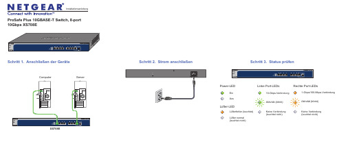
ProSafe Plus 10GBASE-T Switch, 8-port 10Gbps XS708ESchritt 2. Strom anschließen Schritt 1. Anschließen der Geräte XS708EComputer ServerEin AusPower-LEDAktivität (blinkt)Keine Verbindung (leuchtet nicht)10-Gbps-VerbindungLinke Port-LEDsRechte Port-LEDsLüfter-LEDLüfterfehler (leuchtet)Lüfter normal (leuchtet nicht)Aktivität (blinkt)Keine Verbindung (leuchtet nicht)1-Gbps/100-Mbps-VerbindungSchritt 3. Status prüfenNovember 2012Dieses Symbol wurde in Übereinstimmung mit der EU-Richtlinie 2002/96/EG zu Elektro- undElektronik-Altgeräten (WEEE-Richtlinie) hier angebracht. Die Entsorgung dieses Produkts innerhalb der Europäischen Union sollte in Übereinstimmung mit den in Ihrem Land zur Implementierung der WEEE-Richtlinie geltenden Gesetzen gehandhabt werden.NETGEAR, das NETGEAR Logo und Connect with Innovation sind Marken und/oder eingetragene Marken von NETGEAR, Inc. und/oder seiner Tochtergesellschaften in den USA und/oder anderen Ländern. Informationen können ohne vorherige Ankündigung geändert werden. Andere Marken- und Produktnamen sind eingetragene Marken oder Marken der jeweiligen Inhaber. © NETGEAR, Inc. Alle Rechte vorbehalten.In allen Staaten der EU, in EFTA-Staaten und in der Schweiz nur für die Verwendung in Räumen vorgesehen.Die vollständige EU-Konformitätserklärung finden Sie unter /app/answers/detail/a_id/11621/.Hinweis: Zur Verbesserung des internen Designs, des Betriebs und/oder der Zuverlässigkeit behält NETGEAR sich das Recht vor, die in diesem Dokument beschriebenen Produkte ohne vorherige Ankündigung zu ändern. NETGEAR lehnt im Zusammenhang mit dem Einsatz oder der Anwendung der hier beschriebenen Produkte oder Schaltpläne jegliche Haftung ab.Einrichten desSwitch-KonfigurationsprogrammsPlus-Switches sind plug-and-play-fähig. Sie können ein Konfigurationsprogramm installieren, um zusätzliche Optionen auszuwählen, mit denen Sie den Switchverwalten und für Ihr Netzwerk anpassen können. Dieses Dienstprogramm befindet sich auf der Begleit-CD, die Sie zusammen mit dem Switch erhalten haben.Hinweis: Das Konfigurationsprogramm ist auf dem Computer installiert und wird nur auf Windows unterstützt.Installieren Sie das Konfigurationsprogramm:1.Legen Sie die Begleit-CD in einen Computer ein, der an den Switchangeschlossen ist.2.Klicken Sie auf Install ProSafe Plus Utility , und folgen Sie den Anweisungen,um das Programm zu installieren.Das Switch-Konfigurationsprogramm wird in das Programmverzeichnis des Computers installiert, und auf dem Desktop wird ein ProSafe Plus Utility-Symbol erstellt.Konfigurieren Sie den Switch:1.Klicken Sie doppelt auf das ProSafe Plus Utility -Symbol.Plus-Switche, die das Gerät im lokalen Netzwerk ermitteln kann, werden auf der Konfigurations-Startseite angezeigt.2.Wählen Sie den Switch aus, der konfiguriert werden soll.Sie müssen nun das Passwort für den Switch eingeben. 3.Geben Sie dieses in das Passwort-Feld ein.Das Standard-Passwort ist password.4.Konfigurieren Sie den Switch nun mit dem Programm.Eine Beschreibung der Funktionen finden Sie im Benutzerhandbuch zum Thema Konfigurationsprogramm für ProSafe Plus Switch . DasBenutzerhandbuch befindet sich auf der Begleit-CD, aber Sie erreichen es auch über die Links im Hilfe-Bereich des Programms.Technische DatenTechnischer SupportNach der Installation des Geräts können Sie das Produkt unterhttps:// registrieren. Die Seriennummer finden Sie auf dem Etikett Ihres Produkts.Die Registrierung ist Voraussetzung für die Nutzung des telefonischen NETGEAR Supports. NETGEAR empfiehlt, das Gerät über die NETGEAR Webseite zu registrieren. Produkt-Updates und Support im Internet erhalten Sie unter .。
Profile

No.232, Yung- Chang St, Ying-Ko, Taipei, Taiwan 239, R.O.C. Tel :886-2-2678-7966 Fax:886-2-2678-0160
Landrex Organization
President
LUATG
ATG Sales (LSH/LSZ)
Test Program
RDG
*Finance/Accounting *Personnel *Procurement
– CAF – CAM – Mechanical Process – Assembly – QC – Engineering Service (Field Application, Test Program, Test Library)
Taiwan Headquarters
( 66,670ft2 )
Landrex Shenzhen
( 13,068ft2 )
Philippines Rep.
No.232, Yung- Chang St, Ying-Ko, Taipei, Taiwan 239, R.O.C. Tel :886-2-2678-7966 Fax:886-2-2678-0160
No.232, Yung- Chang St, Ying-Ko, Taipei, Taiwan 239, R.O.C. Tel :886-2-2678-7966 Fax:886-2-2678-0160
莫克8口无管理以太网开关产品说明书
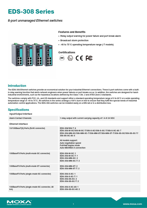
EDS-308Series8-port unmanaged Ethernet switchesFeatures and Benefits•Relay output warning for power failure and port break alarm •Broadcast storm protection•-40to 75°C operating temperature range (-T models)CertificationsIntroductionThe EDS-308Ethernet switches provide an economical solution for your industrial Ethernet connections.These 8-port switches come with a built-in relay warning function that alerts network engineers when power failures or port breaks occur.In addition,the switches are designed for harsh industrial environments,such as the hazardous locations defined by the Class 1Div.2and ATEX Zone 2standards.The switches comply with FCC,UL,and CE standards and support either a standard operating temperature range of 0to 60°C or a wide operating temperature range of -40to 75°C.All switches in the series undergo a 100%burn-in test to ensure that they fulfill the special needs of industrial automation control applications.The EDS-308switches can be installed easily on a DIN rail or in a distribution box.SpecificationsInput/Output InterfaceAlarm Contact Channels1relay output with current carrying capacity of 1A @24VDCEthernet Interface10/100BaseT(X)Ports (RJ45connector)EDS-308/308-T:8EDS-308-M-SC/308-M-SC-T/308-S-SC/308-S-SC-T/308-S-SC-80:7EDS-308-MM-SC/308-MM-SC-T/308-MM-ST/308-MM-ST-T/308-SS-SC/308-SS-SC-T/308-SS-SC-80:6All models support:Auto negotiation speed Full/Half duplex modeAuto MDI/MDI-X connection100BaseFX Ports (multi-mode SC connector)EDS-308-M-SC:1EDS-308-M-SC-T:1EDS-308-MM-SC:2EDS-308-MM-SC-T:2100BaseFX Ports (multi-mode ST connector)EDS-308-MM-ST:2EDS-308-MM-ST-T:2100BaseFX Ports (single-mode SC connector)EDS-308-S-SC:1EDS-308-S-SC-T:1EDS-308-SS-SC:2EDS-308-SS-SC-T:2100BaseFX Ports (single-mode SC connector,80km)EDS-308-S-SC-80:1EDS-308-SS-SC-80:2Standards IEEE802.3for10BaseTIEEE802.3u for100BaseT(X)and100BaseFXIEEE802.3x for flow controlOptical Fiber800Typical Distance4km5km40km80kmWavelen-gthTypical(nm)130013101550TX Range(nm)1260to13601280to13401530to1570 RX Range(nm)1100to16001100to16001100to1600Optical PowerTX Range(dBm)-10to-200to-50to-5 RX Range(dBm)-3to-32-3to-34-3to-34 Link Budget(dB)122929 Dispersion Penalty(dB)311Note:When connecting a single-mode fiber transceiver,we recommend using anattenuator to prevent damage caused by excessive optical power.Note:Compute the“typical distance”of a specific fiber transceiver as follows:Linkbudget(dB)>dispersion penalty(dB)+total link loss(dB).DIP Switch ConfigurationEthernet Interface Port break alarmSwitch PropertiesMAC Table Size2kbitsPacket Buffer Size768KProcessing Type Store and ForwardPower ParametersInput Current EDS-308/308-T:0.07A@24VDCEDS-308-M-SC/S-SC Series,308-S-SC-80:0.12A@24VDCEDS-308-MM-SC/MM-ST/SS-SC Series,308-SS-SC-80:0.15A@24VDC Connection1removable6-contact terminal block(s)Operating Voltage9.6to60VDCInput Voltage Redundant dual inputs,12/24/48VDCReverse Polarity Protection SupportedOverload Current Protection SupportedPhysical CharacteristicsHousing MetalIP Rating IP30Dimensions53.6x135x105mm(2.11x5.31x4.13in)Weight790g(1.75lb)Installation DIN-rail mounting,Wall mounting(with optional kit) Environmental LimitsOperating Temperature Standard Models:-10to60°C(14to140°F)Wide Temp.Models:-40to75°C(-40to167°F) Storage Temperature(package included)-40to85°C(-40to185°F)Ambient Relative Humidity5to95%(non-condensing)Standards and CertificationsHazardous Locations ATEX,Class I Division2EMI CISPR32,FCC Part15B Class AMaritime DNV-GLEMC EN55032/24Vibration IEC60068-2-6EMS IEC61000-4-2ESD:Contact:6kV;Air:8kVIEC61000-4-3RS:80MHz to1MHz:20V/mIEC61000-4-4EFT:Power:2kV;Signal:1kVIEC61000-4-5Surge:Power:2kV;Signal:2kVIEC61000-4-6CS:10VIEC61000-4-8PFMFSafety UL508,UL60950-1,CSA C22.2No.60950-1 Shock IEC60068-2-27Freefall IEC60068-2-32MTBFTime255,528hrsStandards MIL-HDBK-217FWarrantyWarranty Period5yearsDetails See /warrantyPackage ContentsDevice1x EDS-308Series switchInstallation Kit1x cap,plastic,for SC fiber port2x cap,plastic,for SC fiber port(-SC models)2x cap,plastic,for ST fiber port(-ST models) Documentation1x quick installation guide1x warranty cardDimensionsOrdering InformationModel Name 10/100BaseT(X)PortsRJ45Connector100BaseFX PortsMulti-Mode,SCConnector100BaseFX PortsMulti-Mode,STConnector100BaseFX PortsSingle-Mode,SCConnectorOperating Temp.EDS-3088–––0to60°CEDS-308-T8–––-40to75°C EDS-308-M-SC71––0to60°CEDS-308-M-SC-T71––-40to75°C EDS-308-MM-SC62––0to60°CEDS-308-MM-SC-T62––-40to75°C EDS-308-MM-ST6–2–0to60°CEDS-308-MM-ST-T6–2–-40to75°C EDS-308-S-SC7––10to60°CEDS-308-S-SC-T7––1-40to75°C EDS-308-SS-SC6––20to60°CEDS-308-SS-SC-T6––2-40to75°C EDS-308-S-SC-807––10to60°CEDS-308-SS-SC-806––20to60°C Accessories(sold separately)Power SuppliesDR-120-24120W/2.5A DIN-rail24VDC power supply with universal88to132VAC or176to264VAC input byswitch,or248to370VDC input,-10to60°C operating temperatureDR-452445W/2A DIN-rail24VDC power supply with universal85to264VAC or120to370VDC input,-10to50°C operating temperatureDR-75-2475W/3.2A DIN-rail24VDC power supply with universal85to264VAC or120to370VDC input,-10to60°C operating temperatureMDR-40-24DIN-rail24VDC power supply with40W/1.7A,85to264VAC,or120to370VDC input,-20to70°Coperating temperatureMDR-60-24DIN-rail24VDC power supply with60W/2.5A,85to264VAC,or120to370VDC input,-20to70°Coperating temperatureWall-Mounting KitsWK-46Wall-mounting kit,2plates,8screws,46.5x66.8x1mmRack-Mounting KitsRK-4U19-inch rack-mounting kit©Moxa Inc.All rights reserved.Updated Jan30,2019.This document and any portion thereof may not be reproduced or used in any manner whatsoever without the express written permission of Moxa Inc.Product specifications subject to change without notice.Visit our website for the most up-to-date product information.。
户外健身设施
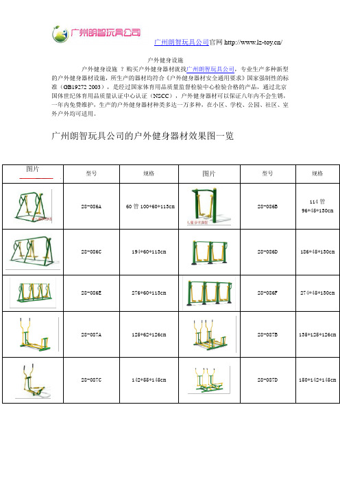
户外健身设施户外健身设施?购买户外健身器材就找广州朗智玩具公司,专业生产多种新型的户外健身器材设施,所生产的器材均符合《户外健身器材安全通用要求》国家强制性的标准(GB19272-2003),是经过国家体育用品质量监督检验中心检验合格的产品,通过北京国体世纪体育用品质量认证中心认证(NSCC),户外健身器材可以保证八年内不会生锈,一年内免费维护,生产的户外健身器材种类多达一万多种,在小区、学校、公园、社区、室外户外均可适用。
广州朗智玩具公司的户外健身器材效果图一览图片型号规格图片型号规格28-086A 60管100*60*113cm 28-086B114管96*45*130cm28-086C 194*60*113cm 28-086D 186*45*130cm 28-086E 276*60*113cm 28-086F 274*45*130cm 28-087A 125*62*126cm 28-087B 135*125*126cm 28-087C 142*55*145cm 28-087D 150*142*145cm28-087E 125*55*85cm 28-087E 85*55*110cm 28-087F 125*120*85cm 28-088A 200*32*150cm 28-088B 245*75*170cm 28-088C 215*215*230cm 28-088D 100*67*155cm 28-088E 250*250*230cm 28-088F 175*10*140cm 28-089A 122*115*75cm 28-089B 165*70*112cm 28-089C 110*40*148cm 28-089D 200*40*148 28-089E 105*80*140cm 28-089F 105*60*140cm 28-090A 155*45*135cm 28-090B 145*35*230cm 28-090C 138*45*230cm28-090D 200*200*140cm 28-090E 140*140*145cm 28-090F 110*110*135cm 28-091A 180*180*180cm 28-091B 165*80*75cm 28-091C 165*60*75cm 28-091D 185*80*75cm 28-091E 140*107*60cm 28-091F 260*110*65cm 28-092A 127*81*145cm 28-092B 105*80*135cm 28-092C 140*100*160cm 28-092D 103*70*170cm 28-092E 126*78*100cm 28-092F 150*78*100cm 28-093A 105*87*145cm 28-093B 85*75*180cm 28-093C 105*87*145cm28-093D 98*41*155cm 28-093E 110*46*115cm 28-093F 158*58*140cm 28-094A 105*83*165cm 28-094B 105*83*165cm 28-094C 105*75*210cm 28-094D 117*78*170cm 28-094E 210*78*210cm 28-094F 250*78*185cm 28-095A 108*108*220cm 28-095B 105*105*280cm 28-095C 108*56*160cm 28-095D 50*50*140cm 28-095E 85*85*115cm 28-095F 230*230*150cm 28-096A 220*60*120cm 28-096B 220*60*120cm 28-096C 280*12*235cm28-096D 420*12*235cm 28-096E 130*30*220cm 28-096F 120*12*220cm 28-097A 360*120*240cm 28-097B 360*140*250cm 28-097C 390*40*280cm 28-097D 360*120*230cm 28-097E 250*120*270cm 28-097F 270*120*240cm 28-098A 95*85*135cm 28-098B 175*85*135cm 28-098C 122*58*125cm 28-098D 120*80*180cm 28-098E 95*70*155cm 28-098F 95*45*105cm 28-099A 140*140*350cm 28-099B 150*110*125cm 28-099C ¢220*130cm 28-099D 280*110*130cm 28-099E 180*80*60cm28-099F 280*100*120cm 28-100A 920*680*250cm 28-100B 780*550*250cm 28-101A 1150*1450*340cm 28-101B 1000*1050*350cm 28-102A 680*680*230cm 28-102B 470*220*390cm 28-103A 500*140*230cm 28-103B 530*110*230cm 28-104A 600*100*160cm 28-104B 600*420*340cm 28-105A 700*570*360cm 28-105B 380*40*300cm 28-106A 274*152*75cm 28-106B 274*152.5*76cm 28-106C 274*152*75cm 28-106D 274*152*75cm 28-106E 274*452*75 28-107A 高155cm 28-107B 高155cm28-107C 高244cm 28-107D 高155cm 28-108A 180*105cm 28-108B 180*105cm 28-108C 180*105cm 28-108D 120*80cm 28-108E 120*80cm 28-108F 120*80cm 28-108G 180*105cm 28-108H 国标高305cm 28-108I 国标高305cm 28-108J 国标高305cm 28-108K 国标高305cm 28-109A 国标高305cm 28-109B 国标高305cm 28-109C 国标高305cm 28-109D 国标高305cm 28-109E 国标高305cm28-109F 国标高305cm 28-109G 国标高305cm28-109H 国标高305cm 28-109I 国标高305cm户外健身器材安装要求和范围:户外健身设施?装户外健身器材的场地及周围环境,应符合下列要求:户外健身设施1、户外健身器材距架空高低压电线的水平距离应不小于3 m;户外健身设施2、户外健身器材距地下管道、地下线路边缘的水平距离应不小于2 m,距各类办公楼房、居民住宅及各类楼堂管所的水平距离应不小于5 m;户外健身设施3、夜间需使用器材的场所,在器材边缘2 m的范围内,光照度应不小于15 lx;户外健身设施4、户外健身器材应远离易燃、易爆和有毒、有害的物品,场地健身应符合国家有关各项安全方面的规定。
公制和英制的金属工字钢和槽钢的型号对照表
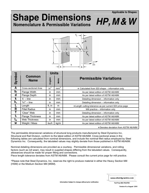
Applicable to Shapes: Shape DimensionsNomenclature & Permissible VariationsHP,M&WUnitsSymbolCommonNameEnglishMetric Permissible VariationsA Cross-sectional Area in2 mm2Õ Calculated from SDI shape – information onlyb f Flange Width in mm As per latest edition of ASTM A6/A6Md Flange Depth in mm As per latest edition of ASTM A6/A6Mk ‘k’ – line in mm Detailing dimension – information onlyk1“k1” – line in mm Detailing dimension – information onlyL Length ft,inmÕLength cutting tolerance as per current SDI price page R Fillet Radius in mm Mill practice – information onlyT ‘Clear” Web in mm Detailing dimension – information onlyt f Flange Thickness in mm As per latest edition of ASTM A6/A6Mt w Web Thickness in mm As per latest edition of ASTM A6/A6Mw Weight / Mass lbs/ft kg/m As per latest edition of ASTM A6/A6MÕDenotes deviation from ASTM A6/A6MThe permissible dimensional variations of structural long products manufactured by Steel Dynamics Inc,Structural and Rail Division, conform to the latest edition of ASTM A6/A6M. Cross-sectional areas in thefollowing tables are calculated from nominal dimensions, and include the nominal fillet radius employed by Steel Dynamics Inc. Consequently, the tabulated values may slightly deviate from those published in ASTM A6/A6M.Nominal detailing dimensions are provided as a courtesy. Permissible dimensional variations, and rollingfactors (such as roll wear), may result in supplied shapes differing from the tabulated values. Consequently, allowances should be made for proper fitting and connections.Piece length tolerance deviates from ASTM A6/A6M. Please consult the current price page for mill practice.*Please note that Steel Dynamics, Inc. reserves the right to produce material in either the Heavy Section Mill (HSM) or the Medium Section Mill (MSM).Wide FlangeBeamsInch-Pound SectionsInch - Pound SizesComparable Metric Sizes Inch - Pound SizesComparable Metric Sizes Prime SectionGroupWeight range in GroupPrime Section Group Weight range inGroupPrime SectionGroupWeight range in GroupPrime Section Group Weight range inGroup (in x in) (lbs/ft) (mm x mm)(kg/m)(in x in) (lbs/ft)(mm x mm)(kg/m)4 x 413 100 x 10019.3 14 x 6.75 30 - 38 360 x 170 44.6 - 5814 x 5 22 - 26360 x 13032.9 - 395 x 5 16 - 19 130 x 13023.8 - 28.116 x 10.2567 - 100 410 x 260 100 - 149 6 x 6 15 - 25 150 x 150 22.5 - 37.1 16 x 7 36 - 57 410 x 180 53 - 85 6 x 4 8.5 - 16 150 x 10013 - 2416 x 5.5 26 - 31410 x 14038.8 - 46.18 x 8 31 - 67 200 x 200 46.1 - 100 18 x 11 76 - 211 460 x 280 113 - 315 8 x 6.5 24 - 28 200 x 170 35.9 - 41.7 18 x 7.5 41 - 71 460 x 190 60 - 106 8 x 5.25 14 - 21 200 x 130 21.0 - 31.3 18 x 6 35 - 46460 x 15052 - 688 x 4 10 - 15 200 x 10015.0 - 22.521 x 12.25101 - 201 530 x 310 150 - 300 10 x 10 49 - 112 250 x 250 73.0 - 167 21 x 8.25 48 - 93 530 x 210 72 - 138 10 x 8 33 - 45 250 x 200 49.1 - 67.0 21 x 6.5 44 - 57530 x 17066 - 8510 x 5.75 16 - 30 250 x 150 24.0 - 44.810 x 4 12 - 19 250 x 10017.9 - 28.424 x 12.75104 - 192 610 x 320 155 - 28524 x 9 56 - 103 610 x 230 83 - 153 12 x 12 65 - 210 310 x 310 97.0 - 313 24 x 7 55 - 62610 x 18082 - 9212 x 10 53 - 58 310 x 250 79 - 8612 x 8 40 - 50 310 x 200 60 - 74 27 x 10 84 - 129690 x 250125 - 19212 x 6.5 21 - 35 310 x 170 31 - 5212 x 4 14 - 22 310 x 10021.0 - 32.730 x 10.5 90 - 132760 x 270134 - 19614 x 14.5 90 - 132 360 x 370 134 - 196 33 x 11.5 118 - 169840 x 290176 - 25114 x 10 61 - 82 360 x 250 91.0 - 12214 x 843 - 53360 x 20064 - 7936 x 12135 - 256920 x 300201 - 381W 4Comparable Metric ShapesNominal Shape DimensionsW 690’sFlangeW E I G H TA r e aD e p t hW i d t hT h i c k n e s sW e b T h i c k n e s sDetailing Distance Fillet RadiusS E C T I O N N A M EC o m p a r a b l e M e t r i c S e c t i o nwAdb ft ft wk k 1 T R P r i m e S e c t i o n G r o u pin x lbs/ft mm x kg/mlbs/ftin2in inininininininin4x4 W4x13 W690x192 13 3.83 4.16 4.060 0.345 0.280 0.680 1.490 2.670 .4003/8W 5Comparable Metric ShapesNominal ShapeDimensionsW 760’sFlangeW E I G H TA r e aD e p t hW i d t hT h i c k n e s sW e b T h i c k n e s sDetailing Distance Fillet RadiusS E C T I O N N A M EC o m p a r a b l e M e t r i c S e c t i o nwAdb ft ft wk k 1 T R P r i m e S e c t i o n G r o u pin x lbs/ft mm x kg/mlbs/ftin2ininininin in ininin5x5 W5x19 W130x28.1 19 5.54 5.15 5.030 0.430 0.270 0.670 1.660 3.490 .4003/8 W5x16 W130x19.316 4.68 5.01 5.000 0.360 0.240 0.640 1.520 3.490 .4003/8Comparable Metric ShapesNominal Shape DimensionsW150sFlangeWeb Detailing Distance*Fillet Radius* *These values depend on the mill.Manual measurements are necessary to confirm.W E I G H TA r e aD e p t hW i d t hT h i c k n e s sT h i c k n e s sMSMHSMMSMHSMS E C T I O N N A M EC o m p a r a b l e M e t r i c S e c t i o nw A d b f t f t w k k 1 T k k 1 T R R P r i m e S e c t i o n G r o u pin x lbs/ft mm x kg/mlbs/ftin 2ininininininininininininW6x25 W150x37.1 25 7.50 6.38 6.080 0.455 0.320 0.860 0.565 4.660 0.855 0.560 4.670 0.405 0.400 W6x20 W150x29.8 20 6.03 6.20 6.020 0.365 0.260 0.770 0.535 4.660 0.765 0.530 4.670 0.405 0.400 6x6W6x15 W150x22.515 4.59 5.99 5.990 0.260 0.230 0.665 0.520 4.660 0.660 0.515 4.670 0.405 0.400W6x16 W150x24 16 4.90 6.28 4.030 0.405 0.260 0.810 0.535 4.660 0.805 0.530 4.670 0.405 0.400 W6x12 W150x18 12 3.71 6.03 4.000 0.280 0.230 0.685 0.520 4.660 0.680 0.515 4.670 0.405 0.400 W6x9 W150x13.5 9 2.84 5.90 3.940 0.215 0.170 0.620 0.490 4.660 0.615 0.485 4.670 0.405 0.400 6x4W6x8.5 W150x138.5 2.67 5.83 3.940 0.194 0.170 0.599 0.490 4.632 0.594 0.485 4.642 0.4050.400Comparable Metric ShapesNominal Shape DimensionsW200sFlangeWeb Detailing Distance*Fillet Radius* *These values depend on the mill.Manual measurements are necessary to confirm.W E I G H TA r e aD e p t hW i d t hT h i c k n e s sT h i c k n e s sMSMHSMMSMHSMS E C T I O N N A M EC o m p a r a b l e M e t r i c S e c t i o nw A d b f t f t w k k 1 T k k 1 T R R P r i m e S e c t i o n G r o u pin x lbs/ftmm x kg/mlbs/ftin 2inininininininininininin8x8 W8x67 W200x100 67 20.10 9.00 8.280 0.935 0.570 1.407 0.757 6.186 1.335 0.685 6.330 0.472 0.400 W8x58 W200x86 58 17.50 8.75 8.220 0.810 0.510 1.282 0.727 6.186 1.210 0.655 6.330 0.472 0.400 W8x48 W200x71 48 14.51 8.50 8.110 0.685 0.400 1.157 0.672 6.186 1.085 0.600 6.330 0.472 0.400 W8x40 W200x59 40 12.16 8.25 8.070 0.560 0.360 1.032 0.652 6.186 0.960 0.580 6.330 0.472 0.400 W8x35 W200x52 35 10.70 8.12 8.020 0.495 0.310 0.967 0.627 6.186 0.895 0.555 6.330 0.472 0.400 W8x31 W200x46.131 9.54 8.00 7.995 0.435 0.285 0.907 0.615 6.186 0.835 0.543 6.330 0.472 0.4008x6½ W8x28 W200x41.7 28 8.66 8.06 6.535 0.465 0.285 0.937 0.615 6.186 0.865 0.543 6.330 0.472 0.400 W8x24 W200x35.924 7.49 7.93 6.495 0.400 0.245 0.872 0.595 6.186 0.800 0.523 6.330 0.472 0.4008x5¼ W8x21 W200x31.3 21 6.64 8.28 5.270 0.400 0.250 0.805 0.530 6.670 0.800 0.525 6.680 0.405 0.400 W8x18 W200x26.618 5.74 8.14 5.250 0.330 0.230 0.735 0.520 6.670 0.730 0.515 6.680 0.405 0.4008x4 W8x15 W200x22.5 15 4.67 8.11 4.015 0.315 0.245 0.720 0.528 6.670 0.615 0.423 6.880 0.405 0.300 W8x13 W200x19.3 13 4.07 7.99 4.000 0.255 0.230 0.660 0.520 6.670 0.555 0.415 6.880 0.405 0.300W8x10W200x15103.207.893.9400.2050.170 0.610 0.490 6.670 0.505 0.385 6.880 0.4050.300Comparable Metric ShapesNominal Shape DimensionsW 250 sFlangeWeb Detailing Distance*Fillet Radius* *These values depend on the mill.Manual measurements are necessary to confirm.W E I G H TA r e aD e p t hW i d t hT h i c k n e s sT h i c k n e s sMSMHSMMSMHSMS E C T I O N N A M EC o m p a r a b l e M e t r i c S e c t i o nw A d b f t f t w k k 1 T k k 1 T R R P r i m e S e c t i o n G r o u pin x lbs/ftmm x kg/mlbs/ftin 2inininininininininininin10x10 W10x112 W250x167 112 33.59 11.36 10.415 1.250 0.755 N/A N/A N/A 1.750 0.878 7.860 N/A 0.500 W10x100 W250x149 100 30.05 11.10 10.340 1.120 0.680 N/A N/A N/A 1.620 0.840 7.860 N/A 0.500 W10x88 W250x131 88 26.54 10.84 10.265 0.990 0.605 N/A N/A N/A 1.490 0.803 7.860 N/A 0.500 W10x77 W250x115 77 23.29 10.60 10.190 0.870 0.530 N/A N/A N/A 1.370 0.765 7.860 N/A 0.500 W10x68 W250x101 68 20.62 10.40 10.130 0.770 0.470 N/A N/A N/A 1.270 0.735 7.860 N/A 0.500 W10x60 W250x89 60 18.29 10.22 10.080 0.680 0.420 N/A N/A N/A 1.180 0.710 7.860 N/A 0.500 W10x54 W250x80 54 16.47 10.09 10.030 0.615 0.370 N/A N/A N/A 1.115 0.685 7.860 N/A 0.500 W10x49W250x7349 15.07 9.98 10.000 0.560 0.340 N/A N/A N/A 1.060 0.670 7.860 N/A 0.50010x8 W10x45 W250x67 45 13.91 10.10 8.020 0.620 0.350 1.277 0.832 7.546 1.120 0.675 7.860 0.657 0.500 W10x39 W250x58 39 12.11 9.927.9850.5300.315 1.187 0.815 7.546 1.030 0.658 7.860 0.6570.500 W10x33W250x49.133 10.35 9.73 7.960 0.435 0.290 1.092 0.802 7.546 0.935 0.645 7.860 0.657 0.50010x5¾ W10x30 W250x44.8 30 9.31 10.47 5.810 0.510 0.300 0.915 0.555 8.640 0.910 0.550 8.650 0.405 0.400 W10x26 W250x38.5 26 8.08 10.33 5.770 0.440 0.260 0.845 0.535 8.640 0.840 0.530 8.650 0.405 0.400 W10x22W250x32.722 6.96 10.17 5.750 0.360 0.240 0.765 0.525 8.640 0.760 0.520 8.650 0.405 0.40010x4 W10x19 W250x28.4 19 5.85 10.24 4.020 0.395 0.250 0.800 0.530 8.640 0.795 0.525 8.650 0.405 0.400 W10x17 W250x25.3 17 5.22 10.11 4.010 0.330 0.240 0.735 0.525 8.640 0.730 0.520 8.650 0.405 0.400 W10x15 W250x22.3 15 4.64 9.99 4.000 0.270 0.230 0.675 0.520 8.640 0.670 0.515 8.650 0.405 0.400W10x12W250x17.9123.779.87 3.960 0.210 0.190 0.615 0.500 8.640 0.610 0.495 8.650 0.4050.400Comparable Metric ShapesNominal Shape DimensionsW 310sFlangeWeb Detailing Distance*Fillet Radius* *These values depend on the mill.Manual measurements are necessary to confirm.W E I G H TA r e aD e p t hW i d t hT h i c k n e s sT h i c k n e s sMSMHSMMSMHSMS E C T I O N N A M EC o m p a r a b l e M e t r i c S e c t i o nw A d b f t f t w k k 1 T k k 1 T R R P r i m e S e c t i o n G r o u pin x lbs/ftmm x kg/mlbs/ftin 2inininininininininininin12x12 W12x210 W310x313 210 63.16 14.71 12.790 1.900 1.180 N/A N/A N/A 2.687 1.377 9.336 N/A 0.787 W12x190 W310x283 190 57.21 14.38 12.670 1.735 1.060 N/A N/A N/A 2.522 1.317 9.336 N/A 0.787 W12x170 W310x253 170 51.38 14.03 12.570 1.560 0.960 N/A N/A N/A 2.347 1.267 9.336 N/A 0.787 W12x152 W310x226 152 46.12 13.71 12.480 1.400 0.870 N/A N/A N/A 2.187 1.222 9.336 N/A 0.787 W12x136 W310x202 136 41.30 13.41 12.400 1.250 0.790 N/A N/A N/A 2.037 1.182 9.336 N/A 0.787 W12x120 W310x179 120 36.66 13.12 12.320 1.105 0.710 N/A N/A N/A 1.892 1.142 9.336 N/A 0.787 W12x106 W310x158 106 32.54 12.89 12.220 0.990 0.610 N/A N/A N/A 1.777 1.092 9.336 N/A 0.787 W12x96 W310x143 96 29.57 12.71 12.160 0.900 0.550 N/A N/A N/A 1.687 1.062 9.336 N/A 0.787 W12x87 W310x129 87 26.95 12.53 12.125 0.810 0.515 N/A N/A N/A 1.597 1.045 9.336 N/A 0.787 W12x79 W310x117 79 24.57 12.38 12.080 0.735 0.470 N/A N/A N/A 1.522 1.022 9.336 N/A 0.787 W12x72 W310x107 72 22.51 12.25 12.040 0.670 0.430 N/A N/A N/A 1.457 1.002 9.336 N/A 0.787 W12x65W310x9765 20.46 12.12 12.000 0.605 0.390 N/A N/A N/A 1.392 0.982 9.336 N/A 0.78712x10 W12x58 W310x86 58 17.98 12.19 10.010 0.640 0.360 N/A N/A N/A 1.427 0.967 9.336 N/A 0.787 W12x53W310x7953 16.50 12.06 9.995 0.575 0.345 N/A N/A N/A 1.362 0.960 9.336 N/A 0.78712x8 W12x50 W310x74 50 15.62 12.19 8.080 0.640 0.370 1.297 0.842 9.596 1.427 0.972 9.336 0.657 0.787 W12x45 W310x67 45 14.14 12.06 8.045 0.575 0.335 1.232 0.825 9.596 1.362 0.955 9.336 0.657 0.787 W12x40W310x6040 12.70 11.94 8.005 0.515 0.295 1.172 0.805 9.596 1.302 0.935 9.336 0.657 0.78712x6.5 W12x35 W310x52 35 10.81 12.50 6.560 0.520 0.300 0.920 0.550 10.660 0.920 0.550 10.660 0.400 0.400 W12x30 W310x44.5 30 9.27 12.34 6.520 0.440 0.260 0.840 0.530 10.660 0.840 0.530 10.660 0.400 0.400 W12x26W310x38.726 8.12 12.22 6.490 0.380 0.230 0.780 0.515 10.660 0.780 0.515 10.660 0.400 0.40012x4 W12x22 W310x32.7 22 6.71 12.31 4.030 0.425 0.260 0.725 0.430 10.860 0.825 0.530 10.660 0.300 0.400 W12x19 W310x28.3 19 5.81 12.16 4.005 0.350 0.235 0.650 0.418 10.860 0.750 0.518 10.660 0.300 0.400 W12x16 W310x23.8 16 4.95 11.99 3.990 0.265 0.220 0.565 0.410 10.860 0.665 0.510 10.660 0.300 0.400W12x14W310x21144.3911.913.970 0.225 0.200 0.525 0.400 10.860 0.625 0.500 10.660 0.3000.400Comparable Metric ShapesNominal Shape DimensionsW 360sFlangeWeb Detailing Distance*Fillet Radius* *These values depend on the mill.Manual measurements are necessary to confirm.W E I G H TA r e aD e p t hW i d t hT h i c k n e s sT h i c k n e s sMSMHSMMSM HSMS E C T I O N N A M EC o m p a r a b l e M e t r i c S e c t i o nw A d b f t f t w k k 1 T k k 1 T R R P r i m e S e c t i o n G r o u pin x lbs/ftmm x kg/mlbs/ftin 2inininininininininininin14x14½ W14x132 W360x196 132 40.15 14.66 14.725 1.030 0.645 N/A N/A N/A 1.817 1.110 11.026 N/A0.787 W14x120 W360x179 120 36.70 14.48 14.670 0.940 0.590 N/A N/A N/A 1.727 1.082 11.026 N/A 0.787 W14x109 W360x162 109 33.42 14.32 14.605 0.860 0.525 N/A N/A N/A 1.647 1.050 11.026 N/A 0.787 W14x99 W360x147 99 30.52 14.16 14.565 0.780 0.485 N/A N/A N/A 1.567 1.030 11.026 N/A 0.787 W14x90W360x13490 27.85 14.02 14.520 0.710 0.440 N/A N/A N/A 1.497 1.007 11.026 N/A 0.78714x10 W14x82 W360x122 82 24.99 14.31 10.130 0.855 0.510 N/A N/A N/A 1.642 1.042 11.026 N/A 0.787 W14x74 W360x110 74 22.72 14.17 10.070 0.785 0.450 N/A N/A N/A 1.572 1.012 11.026 N/A 0.787 W14x68 W360x101 68 20.92 14.04 10.035 0.720 0.415 N/A N/A N/A 1.507 0.995 11.026 N/A 0.787 W14x61W360x9161 18.86 13.89 9.995 0.645 0.375 N/A N/A N/A 1.432 0.975 11.026 N/A 0.78714x8 W14x53 W360x79 53 16.54 13.92 8.060 0.660 0.370 1.317 0.842 11.286 1.447 0.972 11.026 0.657 0.787 W14x48 W360x72 48 15.08 13.79 8.030 0.595 0.340 1.252 0.827 11.286 1.382 0.957 11.026 0.657 0.787 W14x43W360x6443 13.56 13.66 7.995 0.530 0.305 1.187 0.810 11.286 1.317 0.940 11.026 0.657 0.78714x6¾ W14x38 W360x58 38 11.58 14.10 6.770 0.515 0.310 1.172 0.812 11.756 0.915 0.555 12.270 0.657 0.400 W14x34 W360x51 34 10.41 13.986.745 0.455 0.285 1.112 0.800 11.756 0.855 0.543 12.270 0.657 0.400W14x30W360x44.630 9.26 13.84 6.730 0.385 0.270 1.042 0.792 11.756 0.785 0.535 12.270 0.657 0.40014x5 W14x26 W360x39 26 8.10 13.91 5.025 0.420 0.255 1.077 0.785 11.756 0.820 0.528 12.270 0.657 0.400W14x22W360x32.9226.9113.74 5.000 0.335 0.230 0.992 0.772 11.756 0.735 0.515 12.270 0.657 0.400Comparable Metric ShapesDimensionsW 410’sFlangeW E I G H TA r e aD e p t hW i d t hT h i c k n e s sW e b T h i c k n e s sDetailing Distance Fillet RadiusS E C T I O N N A M EC o m p a r a b l e M e t r i c S e c t i o nwAdb ft ft wk k 1 T R P r i m e S e c t i o n G r o u pin x lbs/ft mm x kg/mlbs/ftin2ininininin in ininin16x10¼ W16x100 W410x149100 29.86 16.97 10.425 0.985 0.585 1.655 0.963 13.660 0.670 11/16W16x89 W410x132 89 26.56 16.75 10.365 0.875 0.525 1.545 0.933 13.660 0.670 11/16 W16x77 W410x114 77 23.02 16.52 10.295 0.760 0.455 1.430 0.898 13.660 0.670 11/16 W16x67 W410x100 67 20.09 16.33 10.235 0.665 0.395 1.335 0.868 13.660 0.670 11/1616x7 W16x57 W410x85 57 17.18 16.43 7.120 0.715 0.430 1.385 0.885 13.660 0.670 11/16 W16x50 W410x75 50 15.16 16.26 7.070 0.630 0.380 1.300 0.860 13.660 0.670 11/16 W16x45 W410x67 45 13.67 16.13 7.035 0.565 0.345 1.235 0.843 13.660 0.670 11/16 W16x40 W410x60 40 12.19 16.01 6.995 0.505 0.305 1.175 0.823 13.660 0.670 11/16 W16x36 W410x53 36 10.98 15.86 6.985 0.430 0.295 1.100 0.818 13.660 0.670 11/1616x5½ W16x31 W410x46.1 31 9.54 15.88 5.525 0.440 0.275 1.110 0.808 13.660 0.670 11/16 W16x26 W410x38.826 8.10 15.69 5.500 0.345 0.250 1.015 0.795 13.660 0.670 11/16Comparable Metric ShapesDimensionsW 460’sFlangeW E I G H TA r e aD e p t hW i d t hT h i c k n e s sW e b T h i c k n e s sDetailing Distance Fillet RadiusS E C T I O N N A M EC o m p a r a b l e M e t r i c S e c t i o nwAdb ft ft wk k 1 T R P r i m e S e c t i o n G r o u pin x lbs/ft mm x kg/mlbs/ftin2ininininin in ininin18x11 W18x211 W460x315 211 62.55 20.67 11.555 1.910 1.060 2.580 1.200 15.510 0.670 11/16W18x192 W460x286 192 56.82 20.35 11.455 1.750 0.960 2.420 1.150 15.510 0.670 11/16 W18x175 W460x260 175 51.73 20.04 11.375 1.590 0.890 2.260 1.115 15.520 0.670 11/16 W18x158 W460x235 158 46.73 19.72 11.300 1.440 0.810 2.110 1.075 15.500 0.670 11/16 W18x143 W460x213 143 42.47 19.49 11.220 1.320 0.730 1.990 1.035 15.510 0.670 11/16 W18x130 W460x193 130 38.62 19.25 11.160 1.200 0.670 1.870 1.005 15.510 0.670 11/16 W18x119 W460x177 119 35.47 18.97 11.265 1.060 0.655 1.730 0.998 15.510 0.670 11/16 W18x106 W460x158 106 31.55 18.73 11.200 0.940 0.590 1.610 0.965 15.510 0.670 11/16 W18x97 W460x144 97 28.96 18.59 11.145 0.870 0.535 1.540 0.938 15.510 0.670 11/16 W18x86 W460x128 86 25.72 18.39 11.090 0.770 0.480 1.440 0.910 15.510 0.670 11/16 W18x76 W460x113 76 22.72 18.21 11.035 0.680 0.425 1.350 0.883 15.510 0.670 11/1618x7½ W18x71 W460x106 71 21.26 18.47 7.635 0.810 0.495 1.480 0.918 15.510 0.670 11/16 W18x65 W460x97 65 19.52 18.35 7.590 0.750 0.450 1.420 0.895 15.510 0.670 11/16 W18x60 W460x89 60 18.04 18.24 7.555 0.695 0.415 1.365 0.878 15.510 0.670 11/16 W18x55 W460x82 55 16.61 18.11 7.530 0.630 0.390 1.300 0.865 15.510 0.670 11/16 W18x50 W460x74 50 15.08 17.99 7.495 0.570 0.355 1.240 0.848 15.510 0.670 11/16 18x6 W18x46 W460x68 46 13.95 18.06 6.060 0.605 0.360 1.275 0.850 15.510 0.670 11/16 W18x40 W460x60 40 12.17 17.90 6.015 0.525 0.315 1.195 0.828 15.510 0.670 11/16 W18x35 W460x5235 10.71 17.70 6.000 0.425 0.300 1.095 0.820 15.510 0.670 11/16Comparable Metric ShapesDimensionsW 530’sFlangeW E I G H TA r e aD e p t hW i d t hT h i c k n e s sW e b T h i c k n e s sDetailing Distance Fillet RadiusS E C T I O N N A M EC o m p a r a b l e M e t r i c S e c t i o nwAdb ft ft wk k 1 T R P r i m e S e c t i o n G r o u pin x lbs/ft mm x kg/mlbs/ftin2ininininin in ininin21x12¼ W21x201 W530x300201 59.20 23.03 12.575 1.630 0.910 2.330 1.155 18.370 0.700 11/16W21x182 W530x272 182 53.70 22.72 12.500 1.480 0.830 2.180 1.115 18.360 0.700 11/16 W21x166 W530x248 166 50.29 22.48 12.420 1.360 0.750 2.060 1.075 18.360 0.700 11/16 W21x147 W530x219 147 44.69 22.06 12.510 1.150 0.720 1.850 1.060 18.360 0.700 11/16 W21x132 W530x196 132 40.28 21.83 12.440 1.035 0.650 1.735 1.025 18.360 0.700 11/16 W21x122 W530x182 122 37.33 21.68 12.390 0.960 0.600 1.660 1.000 18.360 0.700 11/16 W21x111 W530x165 111 34.15 21.51 12.340 0.875 0.550 1.575 0.975 18.360 0.700 11/16 W21x101 W530x150 101 31.23 21.36 12.290 0.800 0.500 1.500 0.950 18.360 0.700 11/1621x8¼ W21x93 W530x13893 27.98 21.62 8.420 0.930 0.580 1.630 0.990 18.360 0.700 11/16 W21x83 W530x123 83 24.99 21.43 8.355 0.835 0.515 1.535 0.958 18.360 0.700 11/16 W21x73 W530x109 73 22.13 21.24 8.295 0.740 0.455 1.440 0.928 18.360 0.700 11/16 W21x68 W530x101 68 20.69 21.13 8.270 0.685 0.430 1.385 0.915 18.360 0.700 11/16 W21x62 W530x92 62 18.90 20.99 8.240 0.615 0.400 1.315 0.900 18.360 0.700 11/16 W21x55Õ W530x82 55 16.85 20.80 8.220 0.522 0.375 1.222 0.888 18.356 0.700 11/16 W21x48Õ W530x72 48 14.78 20.62 8.140 0.430 0.350 1.130 0.875 18.360 0.700 11/1621x6½ W21x57 W530x8557 17.38 21.06 6.555 0.650 0.405 1.350 0.903 18.360 0.700 11/16 W21x50 W530x74 50 15.36 20.83 6.530 0.535 0.380 1.235 0.890 18.360 0.700 11/16 W21x44 W530x6644 13.63 20.66 6.500 0.450 0.350 1.150 0.875 18.360 0.700 11/16Comparable Metric ShapesDimensionsW 610’sFlangeW E I G H TA r e aD e p t hW i d t hT h i c k n e s sW e b T h i c k n e s sDetailing Distance Fillet RadiusS E C T I O N N A M EC o m p a r a b l e M e t r i c S e c t i o nwAdb ft ft wk k 1 T R P r i m e S e c t i o n G r o u pin x lbs/ft mm x kg/mlbs/ftin2ininininin in ininin24x12¾ W24x192 W610x285192 57.76 25.47 12.950 1.460 0.810 2.160 1.105 21.150 0.700 11/16W24x176 W610x262 176 53.15 25.24 12.890 1.340 0.750 2.040 1.075 21.160 0.700 11/16 W24x162 W610x241 162 49.20 25.00 12.955 1.220 0.705 1.920 1.053 21.160 0.700 11/16 W24x146 W610x217 146 44.47 24.74 12.900 1.090 0.650 1.790 1.025 21.160 0.700 11/16 W24x131 W610x195 131 40.02 24.48 12.855 0.960 0.605 1.660 1.003 21.160 0.700 11/16 W24x117 W610x174 117 35.85 24.26 12.800 0.850 0.550 1.550 0.975 21.160 0.700 11/16 W24x104 W610x155 104 32.09 24.06 12.750 0.750 0.500 1.450 0.950 21.160 0.700 11/1624x9 W24x103 W610x153 103 30.91 24.53 9.000 0.980 0.550 1.680 0.975 21.170 0.700 11/16 W24x94 W610x140 94 28.34 24.31 9.065 0.875 0.515 1.575 0.958 21.160 0.700 11/16 W24x84 W610x125 84 25.35 24.10 9.020 0.770 0.470 1.470 0.935 21.160 0.700 11/16 W24x76 W610x113 76 23.01 23.92 8.990 0.680 0.440 1.380 0.920 21.160 0.700 11/16 W24x68 W610x101 68 20.71 23.73 8.965 0.585 0.415 1.285 0.908 21.160 0.700 11/1624x7 W24x62 W610x92 62 18.87 23.74 7.040 0.590 0.430 1.290 0.915 21.160 0.700 11/16 W24x55 W610x8255 16.85 23.57 7.005 0.505 0.395 1.205 0.898 21.160 0.700 11/16Comparable Metric ShapesDimensionsW 690’sFlangeW E I G H TA r e aD e p t hW i d t hT h i c k n e s sW e b T h i c k n e s sDetailing Distance Fillet RadiusS E C T I O N N A M EC o m p a r a b l e M e t r i c S e c t i o nwAdb ft ft wk k 1 T R P r i m e S e c t i o n G r o u pin x lbs/ft mm x kg/mlbs/ftin2ininininin in ininin27x10 W27x129 W690x192 129 39.22 27.63 10.010 1.100 0.610 1.801 1.006 24.029 0.701 11/16W27x114 W690x170 114 34.91 27.29 10.070 0.930 0.570 1.631 0.986 24.029 0.701 11/16 W27x102 W690x152 102 31.41 27.09 10.015 0.830 0.515 1.531 0.958 24.029 0.701 11/16 W27x94 W690x140 94 29.03 26.92 9.990 0.745 0.490 1.446 0.946 24.029 0.701 11/16 W27x84 W690x12584 26.13 26.71 9.960 0.640 0.460 1.341 0.931 24.029 0.701 11/16W 30Comparable Metric ShapesNominal Shape DimensionsW 760’sFlangeW E I G H TA r e aD e p t hW i d t hT h i c k n e s sW e b T h i c k n e s sDetailing Distance Fillet RadiusS E C T I O N N A M EC o m p a r a b l e M e t r i c S e c t i o nwAdb ft ft wk k 1 T R P r i m e S e c t i o n G r o u pin x lbs/ft mm x kg/mlbs/ftin2ininininin in ininin30x10½ W30x132 W760x196 132 40.19 30.31 10.545 1.000 0.615 1.701 1.008 26.909 0.701 11/16W30x124 W760x185 124 37.80 30.17 10.515 0.930 0.585 1.631 0.993 26.909 0.701 11/16 W30x116 W760x173 116 35.52 30.01 10.495 0.850 0.565 1.551 0.983 26.909 0.701 11/16 W30x108 W760x161 108 33.04 29.83 10.475 0.760 0.545 1.461 0.973 26.909 0.701 11/16 W30x99 W760x147 99 30.41 29.65 10.450 0.670 0.520 1.371 0.961 26.909 0.701 11/16 W30x90 W760x13490 27.68 29.53 10.400 0.610 0.470 1.311 0.936 26.909 0.701 11/16Comparable Metric ShapesDimensionsW 840’sFlangeW E I G H TA r e aD e p t hW i d t hT h i c k n e s sW e b T h i c k n e s sDistance Fillet RadiusS E C T I O N N A M EC o m p a r a b l e M e t r i c S e c t i o nwAdb ft ft wk k 1 T R P r i m e S e c t i o n G r o u pin x lbs/ft mm x kg/mlbs/ftin2ininininin in ininin33x11½ W33x169 W840x251 169 50.77 33.82 11.500 1.220 0.670 1.921 1.036 29.979 0.701 11/16 W33x152 W840x226 152 46.01 33.49 11.565 1.055 0.635 1.756 1.018 29.979 0.701 11/16 W33x141 W840x210 141 42.82 33.30 11.535 0.960 0.605 1.661 1.003 29.979 0.701 11/16 W33x130 W840x193 130 39.57 33.09 11.510 0.855 0.580 1.556 0.991 29.979 0.701 11/16 W33x118 W840x176118 35.93 32.86 11.480 0.740 0.550 1.441 0.976 29.979 0.701 11/16W 36Comparable Metric ShapesNominal Shape DimensionsW 920’sFlangeW E I G H TA r e aD e p t hW i d t hT h i c k n e s sW e b T h i c k n e s sDistance Fillet RadiusS E C T I O N N A M EC o m p a r a b l e M e t r i c S e c t i o nwAdb ft ft wk k 1 T R P r i m e S e c t i o n G r o u pin x lbs/ft mm x kg/mlbs/ftin2ininininin in ininin36x12 W36x256 W920x381 256 76.81 37.43 12.215 1.730 0.960 2.481 1.231 32.469 0.7513/4 W36x232 W920x345 232 69.55 37.12 12.120 1.570 0.870 2.321 1.186 32.479 0.751 3/4 W36x210 W920x313 210 63.26 36.69 12.180 1.360 0.830 2.111 1.166 32.469 0.751 3/4 W36x194 W920x289 194 58.45 36.49 12.115 1.260 0.765 2.011 1.133 32.469 0.751 3/4 W36x182 W920x271 182 55.06 36.33 12.075 1.180 0.725 1.931 1.113 32.469 0.751 3/4 W36x170 W920x253 170 51.50 36.17 12.030 1.100 0.680 1.851 1.091 32.469 0.751 3/4 W36x160 W920x238 160 48.49 36.01 12.000 1.020 0.650 1.771 1.076 32.469 0.751 3/4 W36x150 W920x223 150 45.68 35.85 11.975 0.940 0.625 1.691 1.063 32.469 0.751 3/4 W36x135 W920x201135 41.20 35.55 11.950 0.790 0.600 1.541 1.051 32.469 0.7513/4H-PileInch-Pound SectionsInch-Pound SizesComparable Metric Sizes Inch-Pound SizesComparable Metric Sizes Prime SectionGroupWeight range in GroupPrime Section Group Weight range inGroupPrime SectionGroupWeight range in GroupPrime Section Group Weight range inGroup (in x in) (lbs/ft) (mm x mm)(kg/m)(in x in) (lbs/ft)(mm x mm)(kg/m)8 x 8 36 200 x 20053 12 x 1253 - 117310 x 31079 - 17410 x 1042 - 57250 x 25062 - 8514 x 141/473 - 117360 x 370108 - 174HP 8Comparable Metric ShapesNominal Shape DimensionsHP 200’sFlangeW E I G H TA r e aD e p t hW i d t hT h i c k n e s sW e b T h i c k n e s sDetailing Distance Fillet RadiusS E C T I O N N A M EC o m p a r a b l e M e t r i c S e c t i o nwAdb ft ft wk k 1 T R P r i m e S e c t i o n G r o u pin x lbs/ft mm x kg/mlbs/ftin2ininininin in ininin8x8 HP8x36 HP200x53 36 10.98 8.02 8.155 0.445 0.445 0.845 0.623 6.329 0.4003/8HP 10Comparable Metric ShapesNominal ShapeDimensionsHP 250’sFlangeW E I G H TA r e aD e p t hW i d t hT h i c k n e s sW e b T h i c k n e s sDetailing Distance Fillet RadiusS E C T I O N N A M EC o m p a r a b l e M e t r i c S e c t i o nwAdb ft ft wk k 1 T R P r i m e S e c t i o n G r o u pin x lbs/ft mm x kg/mlbs/ftin2ininininin in ininin10x10 HP10x57 HP250x8557 17.42 9.99 10.225 0.565 0.565 1.065 0.783 7.859 0.500 1/2 HP10x42 HP250x6242 13.00 9.70 10.075 0.420 0.415 0.920 0.708 7.859 0.500 1/2。
八线4X SDR InfiniBand 端口交换平台用户手册说明书
Eight 4X SDR InfiniBand Port Switch PlatformUser’s ManualPart Number: F-X430066Rev 1.012Eight 4X SDR InfiniBand Port Switch Platform User’s Manual3 ContentsContents 3List of Figures 5 Revision History 7 About this Manual 9 Chapter 1 Overview 11 Chapter 2 Installation and Basic Operation 122.1 Switch Platform Hardware Overview 122.1.1 InfiniBand Connectors 132.1.2 InfiniBand Port LEDs 132.1.3 System Status Indicators 132.1.4 I2C-compatible Bus Connector 132.2 Switch Platform Installation and Operation 132.2.1 Mechanical Installation 142.2.2 Power Connections and Initial Power On 142.2.3 InfiniBand Copper Cable Installation 142.2.3.1 Cable Length Support And IB Port Configuration 15 Chapter 3 Management Tools Overview 163.1 Updating Firmware 163.2 IB Administration 163.2.1 IBADM Requirements 173.2.2 How to Get IBADM 17 Appendix A Specification19 Appendix B Mechanical Drawing20 Appendix C Rack Adapter Installation Instructions21Rev 1.014Rev 1.01Eight 4X SDR InfiniBand Port Switch Platform User’s Manual5 List of FiguresFigure 1: Switch Front and Rear Panels12 Figure 2: Default Configuration Model (Example)16 Figure 3: Switch, Mounting Ears, Screws21 Figure 4: Rear Panel Side with Ear Screws Removed22 Figure 5: Mounting Ear Assembled on Rear Panel Side22 Figure 6: View of Rack Adapter Assembled on Rear Panel Sides23 Figure 7: View of Rack Adapter Assembled on Front Panel Sides23Rev 1.016Rev 1.01Eight 4X SDR InfiniBand Port Switch Platform User’s Manual7 Revision HistoryTable 1 - Revision History TableRevision & Date Description1.01 March 2006Added warnings to Section2.2.2, “Power Connections and Initial Power On,” on page141.00 February 2006First versionRev 1.018Rev 1.01Eight 4X SDR InfiniBand Port Switch Platform User’s Manual9 About this ManualThis manual provides an overview of the Eight 4X SDR InfiniBand Port Switch system and guidelines for its opera-tion. Specifically, it covers the following product:Table 1 - Switch Products Covered in this User’s ManualProduct Number DescriptionF-X430066Eight 4X InfiniBand Port Switch PlatformIntended AudienceThis manual is intended for users and system administrators responsible for installing and setting up the switch plat-form listed above.The manual assumes familiarity with the InfiniBand™ architecture specification.Rev 1.0110Rev 1.01Eight 4X SDR InfiniBand Port Switch Platform User’s Manual11 1 OverviewThis User’s Manual provides an overview of the Eight 4X InfiniBand Port Switch System based on Mellanox Tech-nologies’ MT43132 InfiniScale switch device.The switch platform comes pre-installed with all necessary firmware and configuration for standard operation in an InfiniBand fabric running an InfiniBand compliant Subnet Management software in the subnet. All that is requiredfor normal operation is to follow the usual precautions for installation and connection to the fabric. Once connected, the Subnet Management software automatically configures and begins utilizing the switch.Basic installation and hardware maintenance is covered in “Installation and Basic Operation” on page12. Maintenance and configuration of the switch is done In-Band through the InfiniBand fabric using the IBADM tools package. This package provides the ability to monitor the temperature, voltage, port utilization, and other status parameters in the switch. To upgrade switch firmware, the MFT package is required. See “Management Tools Over-view” on page16.Installation and Basic Operation122 Installation and Basic Operation2.1 Switch Platform Hardware OverviewFigure 1 shows the front and rear panel views of the Eight 4X Ports Switch System, including the I 2C connector and status LEDs.Rear PanelI2C-compatible BusConnectorFront PanelStatusLEDsIB Port 8IB Port 1Figure 1: Switch Front and Rear PanelsLink LEDEight 4X SDR InfiniBand Port Switch Platform User’s Manual132.1.1 InfiniBand ConnectorsAll InfiniBand connectivity is via the rear panel. Figure1 shows the eight 4X InfiniBand port connectors. Each port also includes power supply functionality to support fiber media adapters.2.1.2 InfiniBand Port LEDsTwo IB port LEDs are located to the left of each IB port connector on the rear panel (see Figure1 on page12). The lower (Green) LED is the IB port Physical link LED, and the upper (Yellow) LED is the IB port Logical link LED (Activity LED).Physical Link LED (Green) indications:•Steady On:The Physical link is established•Off:Physical link error, poor connection quality, or no physical connectionActivity LED (Yellow) indications:•Steady On:The Logical link is up but there is no data transfer•Blinking:Data is being transferred to/from the switch port across the cable wires•Off:The Logical link is down2.1.3 System Status IndicatorsTwo system status indicators are located on the left of the rear panel and are labeled “Status” (see Figure1 onpage12). The following status conditions are possible:1.SYSTEM STATUS OK: Green ON, Yellow OFF2.TEMPERATURE ALARM: Yellow ON3.SYSTEM OFF: Green OFF, Yellow OFF4.POWER CIRCUIT ERROR: Green OFF, Yellow OFF (with the power cord connected to power)2.1.4 I2C-compatible Bus ConnectorThe I2C-compatible Bus connector is for factory and development use only.The connector is a female 9 pin D-Type connector. Table1 shows the pinout functions:Table 1 - I2C-compatible Bus Connector Pinout FunctionsPin Number Function1-5GND6SDA8SCL7, 9Not Connected2.2 Switch Platform Installation and OperationInstallation and initialization of the switch platform are straightforward processes, requiring attention to the normal mechanical, power, and thermal precautions for rack-mounted equipment. The switch platform does not require any programming or configuration to operate as a basic InfiniBand switch and includes all of the necessary functionality to operate with external standard InfiniBand Subnet Management software.Installation and Basic Operation14This section describes the installation process and basic operation of the switch platform.2.2.1 Mechanical InstallationThe switch platform is packaged in a 1U chassis. See Table 2, “Switch Platform Mechanical and Environmental Requirements (Worst Case, Fully Populated Chassis)”. If the switch is to be mounted in a standard 19” rack it will require an adapter. Two ear brackets are included (but not assembled) in the packing box of the switch system, which can be assembled on the sides of the chassis acting as the 19” rack adapter, and include rack mounting holes which conform to the IEA-310 standard for such a rack. See “Rack Adapter Installation Instructions” on page 21.Note:The installer should use a rack cable to support the mechanical and environmental charac-teristics of a fully populated switch Chassis as listed in Table 2.Proper ventilation should also be guaranteed for air intake at the front of the chassis and exhaust at the rear in order to maintain good airflow at ambient temperature. Cable routing in particular should not impede the air exhaust from the chassis.Note that the switch platform can be either front or rear mounted. The notion of “front” and “rear” is arbitrary; how-ever, “rear” is used consistently in this manual to refer to the side of the chassis with the InfiniBand connectors.2.2.2 Power Connections and Initial Power OnWarning: The switch platform will automatically power on when AC power is applied. There is no power switch. Make sure the power cable is properly plugged into the system before connecting to power.Warning: The switch platform must be connected to an earthed mains socket-outlet.Warning: In Norway, this system should be connected to the IT power distribution system only .The input voltage is auto-adjusting for a 100-240 V AC, 50-60Hz power connection. The power cord should be a stan-dard 3-wire AC power cord including a safety ground and rated for 2A or higher.2.2.3 InfiniBand Copper Cable InstallationThe switch platform uses industry standard 4X InfiniBand cables which are available from several vendors. The stan-dard 4X cables support full-duplex 10Gb/s wire speed for all switch platform ports. All cables can be inserted or removed with the unit powered on. To insert a cable, press the connector onto the port receptacle until the connector is firmly seated. The GREEN LED indicator to the left of each port will light when the physical connection is estab-lished (that is, when the unit is powered on and a cable is plugged into the port with a functioning port plugged into the other end of the connector). After plugging in a cable, lock the connector using the latching mechanism particular to the cable vendor. To remove, disengage the locks and slowly pull the connector away from the port receptacle. Both LED indicators will turn off when the cable is unseated.Table 2 - Switch Platform Mechanical and Environmental Requirements (Worst Case, Fully Populated Chassis)Rack HeightRack Width Rack Depth Weight Power Ambient Temp.1U12.4”(315mm)w/o Rack Adapter 6.9”(175mm)7.7lb (3.5Kg)45WSingle 100-240 V AC 50-60HzInputMax: 50ºC Min: 0ºC19” (EIA-310)(483mm)w/ Rack AdapterEight 4X SDR InfiniBand Port Switch Platform User’s Manual15Warning:Care should be taken not to impede the air exhaust flow through the ventilation next to the InfiniBand ports. Cable lengths should be used which allow for routing horizontally around to the side of the chassis before bending upward or downward in the rack.2.2.3.1 Cable Length Support And IB Port ConfigurationThe switch platform is configured to drive cables up-to 20 meters long. This configuration allows maximum flexibil-ity in building a robust IB cluster.The selected configuration and cables should meet the required BER specified in the InfiniBand Architecture Specifi-cation, Volume 2, release 1.2.Management Tools Overview 163 Management Tools Overview3.1 Updating FirmwareIn order to update switch firmware, the MFT tools package is needed by Mellanox Technologies. To download this package, visit /support/switch_firmware_table.php. Make sure to also download the MFT User’s Manual and Release Notes. Specifically, the ‘spark’ tool of the MFT package is required for firmware updates. Please see the MFT User’s Manual for details.The most updated firmware is also available for download from the same web page above. Please find the ‘Custom Switch based on Mellanox's MT43132 InfiniScale switch device’ entry in the firmware table.3.2 IB AdministrationTo monitor status conditions in the switch platform, the IBADM tools package is needed (by Mellanox Technolo-gies). IBADM enables the system administrator to manage one or more switch platforms from a single remote Infini-Band host. The features include the following:•Full In-Band Management of Multiple Switch and HCA Systems from single host1•Simple default configuration to get started quickly•Name-based subnet browsing and topology verification•Event monitoring of port statistics, link status and system status for all ports in the switch•Checking and updating the firmware•Intuitive CLI interface•Extensible and customizableThe figure below shows the default configuration model for these tools:Figure 2: Default Configuration Model (Example)One or more switches InfiniBand HCA1.Firmware updates to this Eight 4X IB Port Switch System cannot be performed using ibfwmgr (the burning tool of IBADM pack-age). See Section3.1, “Updating Firmware,” on page16.Eight 4X SDR InfiniBand Port Switch Platform User’s Manual173.2.1 IBADM RequirementsThe general requirements for installing the IBADM software are listed below. Please see the IBADM release notesfor details on platform, OS, Driver and Subnet Management support.puter Platform with an InfiniBand HCA card installed12.HCA Driver3.InfiniBand Compliant Subnet Management. The Open Source SM (Eponyms) is supported.3.2.2 How to Get IBADMPlease visit Mellanox Technologies’s Documents Distribution System at . The IBADM package is available for download under ‘Code Releases/ Tools’. Note that access requires a customer login account. Consult your sales representative for details.1.Any Mellanox Technologies HCA card can be used. Consult your sales representative for other possibilities.Management Tools Overview 18Eight 4X SDR InfiniBand Port Switch Platform User’s Manual19 Appendix A: SpecificationTable 3 - Specification DataPhysical Power and EnvironmentalSize (HxDxW): Size with Rack AdapterWeight:Mounting: 10Gb/s Connector:1U x 6.9” x 12.4” (43.6mm x 175mm x 315mm)1U x 6.9” x 19” (43.6mm x 175mm x 482.6mm)7.7lb (3.5kg)19” RackmountInfiniBandInput V oltage:Maximum Power:Ambient Temperature:Humidity:Altitude:Shock:Vibration:Internal V oltage:100-240 V AC 50-60Hz45W0ºC to 50ºC10% - 90% non-condensing+5 VDCProtocol Support Regulatory ComplianceInfiniBand:QoS: RDMA Support: Management:10Gb/s8 InfiniBand Virtual Lanes for all portsYes, All PortsPerformance, and Device managementAgents for full InfiniBand In-Band Manage-mentSafetyEMCScalability and Performance Reliability, Availability and Serviceability FeaturesSwitching Performance:Addressing:Simultaneous wire-speed any port to any port48K Unicast Addresses Max. per Subnet16K Multicast Addresses per SubnetHot-Swappable:N+1 Redundant:NoneNone20Appendix B: Mechanical Drawing21Appendix C: Rack Adapter Installation InstructionsC.1 Rack Adapter Assembly PartsThe rack adapter assembly parts are included in the switch packing box and are listed in Table 4:C.2 Assembling the Rack AdapterSTEP 1:Remove the pair of screws from the two sides of the chassis where the rack adapter is to be installed. See Figure 4 on page 22.Note: The rack adapter can be installed on the sides close to the front panel or to the rear panel.Table 4 - Rack Adapter Assembly PartsItem QuantityNotes Mounting Ear2See Figure 3Phillips 100° Flat Head, Passivated Stainless SteelUNC Screw 4-40 x ¼2Each mounting ear requires 3 screws. Two additional pairs ofscrews are to be found assembled on the switch chassis sides.Figure 3: Switch, Mounting Ears, ScrewsSTEP 2:Assemble the rack kit as shown in Figure 5.See also Figure 6,“View of Rack Adapter Assembled on Rear Panel Sides” and Figure 7, “View of Rack Adapter Assembled on Front Panel Sides,” on page23.Figure 4: Rear Panel Side with Ear Screws RemovedFigure 5: Mounting Ear Assembled on Rear Panel Side23Figure 6: View of Rack Adapter Assembled on Rear Panel SidesFigure 7: View of Rack Adapter Assembled on Front Panel Sides。
戴尔航空制造业(Durabilt Industries)HCI2系列拨弯槽车辆配件清单说明书

3
220172 3/8” RAKE WHEEL ATTACHMENT LOCK WASHER
6
220089 10mm RAKE WHEEL ATTACHMENT NUT
4
220071 3/8” RAKE WHEEL ATTACHMENT NUT
6
5
300213 RAKE WHEEL COMPLETE RH
300166 RAKE WHEEL COMPLETE LH
6
300492 RAKE WHEEL TINE
7
300412 RAKE WHEEL TINE CLAMP
220249 RAKE WHEEL TINE CLAMP BOLT
220089 RAKE WHEEL TINE CLAMP NUT
5
2,3,4
6
POSITION 1 2
3
PART NUMBER 300649
300486 600161
600347 600162 600163
600348 600164 612418 612419 612420 612421 612401 612402
DESCRIPTION
FRONT WHEEL ARM RETAINING PIN FRONT WHEEL ARM RETAINING PIN RETAINER CLIP
4
4
300659 PIVOT PIN O’RINGS
4
5
220273 PIVOT PIN RETAINING BOLT
2
6
220096 PIVOT PIN RETAINING NUT
2
7
612304 INNER WING ANGLE STRUT
B18系列产品说明书

*(XXX)CO
4
MC/AC
4
1/2" [13] & 3/4" [19]
Attaches to 1/8" [3] through 1/4" [6] flange.
4
1" [25]
4
MC/AC
4
1/2" [13] & 3/4" [19]
other purpose.
NOTE: All load ratings are for static conditions and do not account for dynamic loading such as wind, water or seismic loads, unless otherwise noted.
Pentair, CADDY, ERICO CADWELD, ERICO CRITEC, ERICO, ERIFLEX, and LENTON are owned by Pentair or its global affiliates. All other trademarks are the property of their respective owners. Pentair reserves the right to change specifications without prior notice.
CADDY B18 series with threaded rod going through both
the B18 and the box, this single support is appropriate.
- 1、下载文档前请自行甄别文档内容的完整性,平台不提供额外的编辑、内容补充、找答案等附加服务。
- 2、"仅部分预览"的文档,不可在线预览部分如存在完整性等问题,可反馈申请退款(可完整预览的文档不适用该条件!)。
- 3、如文档侵犯您的权益,请联系客服反馈,我们会尽快为您处理(人工客服工作时间:9:00-18:30)。
Standard grades / Glass fiber reinforced Rubber modified (PC+SAN) blend; 31 % glass fiber filled; injection molding grade; optimized heatageing- and UV-stability; very good flow; tensile modulus = 10000 MPa; Vicat/B 120 = 134 °C. ISO ShortnameProperty Test Condition Unit Standard Value-Rheological propertiesMolding shrinkage, parallel150x105x3; 260 °C / MT 80 °C% b.o. ISO 25770.15 - 0.35 Molding shrinkage, normal150x105x3; 260 °C / MT 80 °C% b.o. ISO 25770.3 - 0.5 Melt viscosity1000 s-1; 260 °C Pa·s b.o. ISO 11443-A250Mechanical properties (23 °C/50 % r. h.)C Tensile modulus 1 mm/min MPa ISO 527-1,-210000C Stress at break 5 mm/min MPa ISO 527-1,-2135C Strain at break 5 mm/min%ISO 527-1,-2 2.0Izod impact strength23 °C kJ/m²ISO 180-U40 Izod impact strength-30 °C kJ/m²ISO 180-U40 Izod notched impact strength23 °C kJ/m²ISO 180-A12 Izod notched impact strength-30 °C kJ/m²ISO 180-A11 Thermal propertiesC Temperature of deflection under load 1.80 MPa°C ISO 75-1,-2126C Temperature of deflection under load0.45 MPa°C ISO 75-1,-2134C Vicat softening temperature50 N; 50 °C/h°C ISO 306132Vicat softening temperature50 N; 120 °C/h°C ISO 306134C Coefficient of linear thermal expansion, parallel23 to 55 °C10-4/K ISO 11359-1,-20.25C Coefficient of linear thermal expansion, transverse23 to 55 °C10-4/K ISO 11359-1,-20.6C Burning behavior UL 940.85 mm Class UL 94HB (Bayer Test)Electrical properties (23 °C/50 % r. h.)C Relative permittivity100 Hz-IEC 60250 3.6C Relative permittivity 1 MHz-IEC 60250 3.4C Dissipation factor100 Hz10-4IEC 6025030C Dissipation factor 1 MHz10-4IEC 6025085C Volume resistivity Ohm·m IEC 600931E14C Surface resistivity Ohm IEC 600931E17C Electrical strength 1 mm kV/mm IEC 60243-135C Comparative tracking index CTI Solution A Rating IEC 60112175Other properties (23 °C)C Water absorption (saturation value)Water at 23 °C%ISO 620.4C Water absorption (equilibrium value)23 °C; 50 % r. h.%ISO 620.1C Density kg/m³ISO 1183-11375Glass fiber content Method A% b.o. ISO 3451-131Processing conditions for test specimensC Injection molding-Melt temperature°C ISO 294260C Injection molding-Mold temperature°C ISO 29480C Injection molding-Injection velocity mm/s ISO 294540C These property characteristics are taken from the CAMPUS plastics data bank and are based on the international catalogue of basic data for plastics according to ISO 10350.Impact properties: N = non-break, P = partial break, C = complete breakDisclaimerDisclaimer for Sales productsThis information and our technical advice - whether verbal, in writing or by way of trials - are given in good faith but without warranty, and this also applies where proprietary rights of third partiesare involved. Our advice does not release you from the obligation to check its validity and to test our products as to their suitability for the intended processes and uses. The application, use and processing of our products and the products manufactured by you on the basis of our technical advice are beyond our control and, therefore, entirely your own responsibility. Our products are sold in accordance with the current version of our General Conditions of Sale and Delivery.Test valuesUnless specified to the contrary, the values given have been established on standardized test specimens at room temperature. The figures should be regarded as guide values only and not as binding minimum values. Please note that, under certain conditions, the properties can be affected to a considerable extent by the design of the mold/die, the processing conditions and coloring. Processing noteUnder the recommended processing conditions small quantities of decomposition product may be given off during processing.To preclude any risk to the health and well-being of the machine operatives, tolerance limits for the work environment must be ensured by the provision of efficient exhaust ventilation and fresh air at the workplace in accordance with the Safety Data Sheet. In order to prevent the partial decomposition of the polymer and the generation of volatile decomposition products, the prescribed processing temperatures should not be substantially exceeded. Information Impact propertiesImpact properties: N = non-break, P = partial break, C = complete breakPublisher: Global Innovations - PolycarbonatesBayer MaterialScience AG,D-51368 Leverkusen,pcs-info@。