ETB-01-中文-LH
浙江易液泵有限公司 进化10500、12500、16500、18000系列泵机说明书

OWNER’S MANUALEVOLUTION 10500, 12500, 16500, & 18000 SERIES PUMPSIMPORTANT SAFETY INSTRUCTIONSWhen installing and using this electrical equipment, basic safety precautions should always be followed, including the following:1. READ AND FOLLOW ALL INSTRUCTIONS2. WARNING – To reduce the risk of injury, do not permit children to use thisproduct unless they are closely supervised at all times.3. Do not install within an outer enclosure unless so marked.4. SAVE THESE INSTRUCTIONS.WARNING– All electrical wiring of the motor installation must be done by a qualified electrician in accordance with applicable electrical codes. Before working on any motor, be certain that the source of electrical power is off at the main junction box.BONDING WIRE – Upon installation of the pump, the motor must be used with a No. 8 AWG (8.4mm2) solid copper conductor per National Electric Code. The connection should be from the accessible wire connector on the motor to all metal parts of the water garden and to all electrical equipment, metal conduit and metal piping within 5 feet (1.5m) of the inside walls of the water garden, when the motor is installed within 5 feet of the inside walls of the water garden.NOTE: For electrical connection, see wiring diagram on motor rating plate.CAUTION: This Pump Has Been Evaluated for Use With Water Only.WARNING Risk of Electric Shock – This pump is supplied with a grounding conductor and grounding-type attachment plug. To reduce the risk of electric shock, be certain thatit is connected to a properly grounded, grounding-type receptacle. (56.1 b)INSTALLATION & OPERATING INSTRUCTIONS GENERALYour Evolution pump has been quality built and engineered to give maximum efficiency under normal water pumping conditions. Consult the manufacturer for any other applications. INSTALLATIONI. LOCATION OF PUMPFor best pump performance, locate the system as close to the water source as possible. Provide adequate access around the pump for inspection and maintenance. Place pump on a firm level surface. Pump need not be bolted down unless required by local code.II. MODELS WITH TRAPAvoid excessive tightening of pipe or fittings in any areas where threaded connections are used. For NPT threaded connections, use Quick-Seal Teflon Thread Sealing Compound, Plasto-Joint Stick or any other sealants formulated specifically for plastics. OPERATIONI. STARTING & PRIMING PUMPDo not run unit dry. Always be certain that the pump casing and/or trap is filled with water before starting the unit. Allow a reasonable amount of time for priming. If pump will not start, or will not prime, see trouble shooting section of this manual.II. MAINTENANCEThe trap basket should be inspected frequently and kept clean. To avoid damage to the basket, do not strike when cleaning. Inspect trap cover O-ring regularly and replace as necessary.CAUTION: Do not remove hair and lint strainer lid while pump is running or under pressure! Lid is held in place by lock handles, which can be removed or tightened by hand. Basket must be kept clear of leaves and debris at all times. Keep motor clean. Insure that louvered openings are free from debris and obstructions. Over a period of time, the shaft seals may become damaged or worn and must be replaced. III. WINTERIZATIONTo prevent damage during freezing conditions, turn off all electrical power. Drain thoroughly and clean out any debris. Protect pump and motor from elements by covering or if possible, store in dry well ventilated room.MOTORYour pump is equipped with a permanently lubricated, maintenance-free, heavy-duty industrial quality motor especially designed to withstand the heavy-duty requirements of water garden application. Wiring connection must agree with incoming line voltage. Improper wiring can cause serious injuries and damage to the motor, voiding warranty. (For wiring instructions, see diagram on motor rating plate.)NOTE: Motor is designed to withstand the effects of normal rainfall. To increase the life of your motor observe the following:1.) Do not flood the motor or submerge in water. Todo so voids warranty.2.) Provide ample cross ventilation, minimum of 6” atall points.3.) Keep motor and surrounding area clean.4.) Avoid sweeping or stirring dust near motor whileit is running.5.) Avoid storing or spilling dry chemicals, powders,etc. near motor.6.) Provide protection against the elements.7.) Locate motor on a slight elevation so water willdrain away from motor.8.) Avoid spilling or dripping liquid chemicals on ornear motor.9.) Avoid splashing water or hosing area near motor.Water damage voids warranty. For replacements contact your local supplier or authorized serviceman.TROUBLESHOOTINGMOTOR WILL NOT START:1. Check Circuit Breakers2. Check for incorrect or loose wire connections.3. Make sure the correct power supply is being used.4. Any on/off switch or pneumatic switch should be in the “on” mode.MOTOR OVERHEATING AND CYCLING ON AND OFF:1. Check for incorrect or loose wire connections.2. Check for low voltage supply (frequently caused by undersized wire).3. Make sure the motor gets a fresh air supply and the vents are kept unclogged.MOTOR MAKES HUMMING NOISE BUT WILL NOT START:1. Make sure motor shaft turns free.2. Check for jammed impeller or an obstruction in (volute) casing.3. Check for low voltage and undersized wire.PUMPS WILL NOT PRIME1. Make sure pump is installed at the proper level and the plumbing lines hae been correctly installedto allow the water to enter pump freely.2. Open air control valves to release any possible air lick.3. Make sure all suction and discharge lines are clear and unobstructed and all valves are opened.4. Check for air leaks in the suction line.LOW WATER FLOW:1. Check filter pressure gauge, filter may need cleaning.2. Check for clogged plumbing lines.3. Check for worn or damaged impeller.4. Check for low voltage.WATER LEAKS:1. Check contamination or damage to shaft rotary seal. Replace if necessary.2. Check compression fitting (union connectors), make sure they are properly aligned and secured.Hand tighten only. Do not use tools.3. Make sure O-ring is properly seated and not damaged.NOISES:1. Check plumbing vibration-make sure lines are adequately supported.2. Check for cavitations, due to obstruction in or undersized suction line.IF PUMP LOSES PRIME, OR TOO MANY BUBBLES COME THROUGH RETURN LINE CHECK:1. Hair and lint pot cover is tight and O-ring is in place and free from defects.2. Valves on suction and return lines are working properly and open.3. Water level in water garden is too low.4. Filter O-ring or gasket is in place and free from defects.5. All fittings and connections are secure and air tight.EVOLUTION ASSEMBLY INSTRUCTIONS(Including Impeller and Seal Replacement)WARNING: ALWAYS DISCONNECT THE ELECTRICAL POWER FROM THE PUMP MOTOR BEFORE PERFORMING ANY WORK ON THE PUMP UNIT.To Disassemble Pump:CAUTION: DRAIN THE WATER FROM THE PLUMBING LINES BEFORE DISCONNECTING THE PUMP, ALWAYS PROTECT THE MOTOR FROM POSSIBLE WATER DAMAGE.Removing Suction Cover:1. Remove the cover by removing the screws securing the cover to the volute (casing). These screwsare located at the perimeter of the cover.2. Note the orientation of the loose wear ring on the impeller hub before disassembling.Removing Impeller:1. Hold the motor shaft from rotating as follows: At the rear of the motor, insert a wide bladescrewdriver in the shaft end slot, or use a needle nose “vise grip” or pliers to hold the shaft between the motor face and impeller sleeve opening. Caution: Do not grip impeller sleeve.2. Turn the impeller counter clockwise until it is completely free from the motor shaft thread. Removing the Volute (Casing) from the Motor:1. Unscrew the four (4) bolts located at the rear of the motor. These bolts extend through the entirelength of the motor into the 4 legs of the volute.2. When the 4 legs of the volute are completely disengaged from all the bolts, slide the volute off ofthe motor shaft.Inspecting the Seal:1. Carefully examine the surfaces of the carbon disk (black rigid part of seal rotating assembly,mounted on impeller) and the white ceramic ring (at seal stationary assembly on volute) for edge chipping, surface scratches, or uneven wear. The surfaces should be smooth and free from damage.2. The rest of the seal assembly should be free from cracks and should fit snugly with their respectivemating parts.3. Use alcohol wipes or isopropyl alcohol with clean “lint free” soft cloth to clean the carbon disk andthe ceramic ring surface if reusing the same assemblies.NOTE: IT IS ADVISABLE TO REPLACE THE COMPLETE SEAL ASSEMBLY (BOTH THE CERAMIC AND CARBON SIDES) EVERYTIME THE PUMP IS DISSASSEMBLED.Removing the Seal Assemblies:1. Remove the seal rotating assembly from the impeller by carefully sliding if off the impeller sleeve.2. Remove the ceramic ring and rubber boot by knocking it out and/or prying it loose through the rearopening of the volute. Be sure not to scratch or damage the ceramic surface if you are reusing this part. Caution must be used so as not to damage the volute wall.Installing the New Seal Assemblies:1. Seal Rotating Assembly: Carbon Disk, Spring, Steel Collar, Rubber ringa. Before installing the seal rotating assembly, apply water to the shaft sleeve.b. Grasp the assembly with the carbon disk facing outward. Insert the impeller sleeve through thesteel collar side. Using a twisting motion, push until the steel collar touches the base of thesleeve.2. Seal Stationary Assembly: Ceramic Ring, Rubber Boota. Before installing the stationary assembly, apply water to the rubber boot’s ribbings.b. Being careful not to damage the ceramic ring surface, press the seal assembly squarely intothe seal cavity of the volute.Reinstalling the Volute (Casing) to the Motor:1. Align the four bolts located at the rear of the motor, with the 4 volute legs. These bolts extendthrough the entire length of the motor, into the legs of the volute.2. Pre-tighten the four bolts. Make sure that the motor shaft is accurately located in the center of (nottouching) the ceramic ring.3. When the motor shaft is properly located, tighten the four bolts to secure the volute in place. Reinstalling the Impeller:1. Hold the motor shaft from rotating as follows: At the rear of the motor, insert a wide bladescrewdriver in the shaft end slot, or use a needle nose “vise grip” or pliers to hold the shaft between the motor face and impeller sleeve opening.2. Thread the impeller clockwise over the motor shaft. Hand tighten only. Make sure the seal carbondisk is in contact with ceramic ring. Caution: Do not grip impeller sleeve.3. Reinstall the wear ring over the impeller hub in correct orientation.Reinstalling the Suction Cover:1. Inspect the o-ring for damage. Replace if necessary.2. Properly install the o-ring on the cover before mounting the cover to the volute.3. Cover can be mounted to the volute in one orientation only. An “aligning” feature is built-in witheach part, to ensure proper mounting. When properly aligned, the cover should slide in easily.4. Secure the cover to the volute with screws. Tighten all screws alternately (crisscrossing the cover)to achieve proper o-ring compression and cover seating.5. Rotate the impeller by hand to make sure that it is rotating freely, without any interference. Reconnecting the Pump Unit:1. Clean the seals, gaskets, or o-rings of the plumbing connectors. Replace if cracked, worn, ordamaged.2. Reconnect the plumbing lines to the pump. Hand tighten only.3. Be sure that the pump unit is secured properly to the platform or base, if applicable. Tighten thebolts if necessary.4. Reconnect the power supply. Be sure that all wires are properly and securely connected.To order replacement parts please contact your local authorized dealer.CAUTION: BEFORE TURNING THE POWER ON, BE SURE THAT: 1) THERE IS AN ADEQUATE AMOUNT OF WATER IN THE SYSTEM; 2) ALL VALVES ARE OPEN TO ALLOW WATER CIRCULATION; 3) ALL CONNECTORS AND FITTINGS ARE PROPERLY ALIGNED AND SECURE.EVOLUTION SERIES PUMP LIMITED WARRANTYAdvantage Manufacturing, Inc.WARRANTS TO:The original retail purchaser only, that the products they manufacture are free from defects in material and/or workmanship for a period of one year (pump seals warranty for 30 days) from date of purchase. If within the first two years, any such products shall prove defective, it shall be repaired or replaced at Advantage Manufacturing Inc.’s option as follows:The original retail purchaser shall first contact the installing dealer, as soon as possible after discovery of the defect, but in no event later than the expiration date of this warranty. Or upon notification,Advantage Manufacturing, Inc.Customer Service Department624B South B Street, Tustin, CA 92780Will advise the consumer of the address to which the defective item may be shipped, together with the model number, serial number and date of purchase of item claimed to be defective. The consumer must pay for all shipping charges. EXCLUSIONS:1. This warranty shall not apply to any failuresresulting from negligence, abuse, misuse,misapplication, improper installation, alterationor modification, chemical corrosion, orimproper maintenance.2. Any items manufactured by other companiesand used by Advantage Manufacturing, Inc. inits products may carry warranties by theoriginal manufacturers.3. Advantage Manufacturing, Inc. is not liable forincidental or consequential damages, loss oftime, inconvenience, incidental expenses, laboror material charges in connection with removalor replacement of the equipment.4. Advantage Manufacturing, Inc. is notresponsible for any implied warranties orrepresentations by others and the foregoingwarranty is exclusive and in lieu of allwarranties provided herein.Some states do not allow the exclusion or limitation of incidental or consequential damages, so the above limitation or exclusion may not apply to you.This warranty gives you specific legal rights and you may also have other rights, which vary from state to state.Advantage Manufacturing, Inc.624B South B StreetTustin, CA 92780TEL: 714-505-1166 / FAX: 714-505-1160。
伊万ET201视波表使用说明书

目录
安全须知 .................................................................................................................................................................................. 3 仪表简介 .................................................................................................................................................................................. 5
ห้องสมุดไป่ตู้序言
尊敬的用户; 感谢您选择 ET201/ET202 数字存储视波万用表。能看到波形的数字视波万用表是伊万科技的专利产品,是测量仪表从模
拟(指针)、数字显示到视波表发展的必然产物。相信该产品创新的功能组合、人性化的设计会给您现场检测带来极大的方便。 使用前,请仔细阅读本手册内容,尤其“安全须知”部分。阅读后请将此手册妥善保管,以备需要时随时查阅。
ABB变频器、变流器和逆变器选项 FDCO-01 02 DDCS通信模块用户手册

—OPTIONS FOR ABB DRIVES, CONVERTERS AND INVERTERSFDCO-01/02 DDCS communication modulesUser’s manual—List of related manualsYou can find manuals and other product documents in PDF format on the Internet. See section Document library on the Internet on the inside of the back cover. For manuals not available in the Document library, contact your local ABB representative.*Available in the Document library*Lists of hyperlinks to product manuals CodeACS880-019AKK105408A7004ACS880-049AKK105713A4819ACS880-07 (45 to 710 kW)9AKK105408A8149ACS880-07 (560 to 2800 kW) 9AKK105713A6663ACS880-07CLC drives 9AKK107046A0239ACS880-07LC drives 9AKK107680A9275ACS880-11 drives9AKK106930A9565ACS880-14 drive modules 9AKK107045A8023ACS880-17 (45 to 400 kW)9AKK106930A3466ACS880-17 (160 to 3200 kW)9AKK106354A1499ACS880-17LC drives 9AKK107492A4721ACS880-31 drives9AKK106930A9564ACS880-34 drive modules 9AKK107045A8025ACS880-37 (45 to 400 kW)9AKK106930A3467ACS880-37 (160 to 3200 kW)9AKK106354A1500ACS880-37LC drives 9AKK107492A4722ACS880 multidrives9AKK106103A9122ACS880 multidrive modules9AKK105713A3673Option manuals and guidesFDCO-01/02 DDCS communication modules user’s manual3AUA00001140583 Table of contents1. FDCO-01/02 DDCS communication modules Introduction to the manual . . . . . . . . . . . . . . . . . . . . . . . . . . . . . . . 5 Safety in installation and maintenance . . . . . . . . . . . . . . . . . 5 Target audience . . . . . . . . . . . . . . . . . . . . . . . . . . . . . . . . . . . . . . 6Terms and abbreviations . . . . . . . . . . . . . . . . . . . . . . . . . . . . . 6 Hardware description . . . . . . . . . . . . . . . . . . . . . . . . . . . . . . . . . . . . 6 Layout . . . . . . . . . . . . . . . . . . . . . . . . . . . . . . . . . . . . . . . . . . . . . . . .7 Mechanical installation . . . . . . . . . . . . . . . . . . . . . . . . . . . . . . . . . . . .7 Unpacking and checking the delivery . . . . . . . . . . . . . . . . . . .7 Installing the module . . . . . . . . . . . . . . . . . . . . . . . . . . . . . . . . . 8 Electrical installation . . . . . . . . . . . . . . . . . . . . . . . . . . . . . . . . . . . . . 9 Diagnostics . . . . . . . . . . . . . . . . . . . . . . . . . . . . . . . . . . . . . . . . . . . . 10 LEDs . . . . . . . . . . . . . . . . . . . . . . . . . . . . . . . . . . . . . . . . . . . . . . . 10 Technical data . . . . . . . . . . . . . . . . . . . . . . . . . . . . . . . . . . . . . . . . . . 10 Dimension drawing . . . . . . . . . . . . . . . . . . . . . . . . . . . . . . . . . . 10 Installation . . . . . . . . . . . . . . . . . . . . . . . . . . . . . . . . . . . . . . . . . .11 Degree of protection . . . . . . . . . . . . . . . . . . . . . . . . . . . . . . . . .11 Ambient conditions . . . . . . . . . . . . . . . . . . . . . . . . . . . . . . . . . .11 Package . . . . . . . . . . . . . . . . . . . . . . . . . . . . . . . . . . . . . . . . . . . . .11 Connectors . . . . . . . . . . . . . . . . . . . . . . . . . . . . . . . . . . . . . . . . . .11 Operating voltage . . . . . . . . . . . . . . . . . . . . . . . . . . . . . . . . . . . .11 Current consumption . . . . . . . . . . . . . . . . . . . . . . . . . . . . . . . . .11 General . . . . . . . . . . . . . . . . . . . . . . . . . . . . . . . . . . . . . . . . . . . . . .12 Further information4FDCO-01/02 DDCS communication modules 5FDCO-01/02 DDCS communication modulesIntroduction to the manualSafety in installation and maintenanceThese instructions are for all who install or connect an optional module to a drive, converter or inverter and need to open its front cover or door to do the work.WARNING! Obey these instructions. If you ignore them,injury or death, or damage to the equipment can occur.•If you are not a qualified electrician, do not do installation or maintenance work.•Disconnect the drive, converter or inverter from all possible power sources. After you have disconnected the drive, converter or inverter, always wait for 5 minutes to let the intermediate circuit capacitors discharge before you continue.•Disconnect all dangerous voltages connected to other control signal connectors in reach. For example, it ispossible that 230 V AC is connected from outside to a relay output of the drive, converter or inverter.•Use a voltage tester to measure that there are no live parts within reach.6 FDCO-01/02 DDCS communication modules⏹Target audienceThis manual is intended for people who plan the installation,install, start up, use and service the communication module. Before you do work on the module, read this manual and theapplicable drive, converter or inverter manual that containsthe hardware and safety instructions for the product in question.You are expected to know the fundamentals of electricity, wiring, electrical components and electrical schematic symbols.The manual is written for readers worldwide. Both SI and imperial units are shown.⏹Terms and abbreviationsLater in this manual, term drive substitutes for stringdrive/converter/inverter.Hardware descriptionThe FDCO DDCS communication module enables fiber opticconnection on the DDCS protocol for ABB drives. The module includes the connectors for fiber optic DDCS channels Ch A and Ch B (see 1 and 2 below) and selectors for both channels to make sure that the transmitter current is optimal for the cable length (see 3 and 4 below).The module makes the signal and power connection to the drive through a 20-pin connector.FDCO-01/02 DDCS communication modules 7⏹Layout5437612Mechanical installation⏹Unpacking and checking the delivery1.Open the package.2.Make sure that the package contains:•FDCO-01/02 module•This manual.3.Make sure that there are no signs of damage.8 FDCO-01/02 DDCS communication modulesInstalling the moduleWARNING! Obey the safety instructions. If you ignorethe safety instructions, injury or death can occur.See the drive hardware manual for the position of the modulein the drive. Plastic pins, a lock and one screw hold the module in place. The screw also makes an electrical connectionbetween the module and drive frame for cable shieldtermination.To install or remove the module from the control unit:1.Pull out the lock.2.Put the module carefully into its position on the drive.3.Push in the lock.4.Tighten the screw to 0.8 N·m (7 lbf·in).Note: It is necessary to tighten the screw correctly to fulfillthe EMC requirements and to ensure the correct operationFDCO-01/02 DDCS communication modules 9 Electrical installationNotes:•Transmitter and receiver have to be of the same type at both ends of the link.•Observe color coding and terminal markings so that transmitters are connected to receivers and vice versa.•If multiple devices are to be connected to one channel, connect them in a ring.1.Lead the fiber optic cables from the external device to theappropriate channel(s) of the FDCO-01/02.2.Inside the drive, route the cables as shown in its hardwaremanual. Make sure the cables are not kinked or laid against sharp edges.3.Select switch positions for both channels to match thecable lengths according to the following table.Using a transmitter current that is higher thanrecommended reduces LED lifetime and increases power consumption and heat generation.Switch position TransmittercurrentCable lengthPOF, 1mm HCS, 200 µm *0 - OFF0 mA Disabled1 - SHORT30 mA0.1 … 20 m0.1 … 50 m2 - MEDIUM40 mA20…25 m50…100 m3 - LONG50 mA25…30 m100…200 m * HCS cannot be used with FDCO-02 channel A.10 FDCO-01/02 DDCS communication modules Diagnostics⏹LEDsFDCO-01/02 DDCS communication modules 11⏹InstallationInto an option slot on the drive control unit⏹Degree of protectionIP20⏹Ambient conditionsThe applicable ambient conditions specified for the drive in its hardware manual are in effect.⏹PackageCardboard. Plastic wrapping: Antistatic air bubble sheet (PE).⏹Connectors•20-pin F-series module connector• 2 transmitter/receiver connector pairs for fiber optic cables •Baud rates:⏹Operating voltage3.3 V DC (supplied by the drive control unit)⏹Current consumption300 mA maxModule type Channel A (Ch A)Channel B (Ch B)FDCO-0110 MBd 10 MBd FDCO-025 MBd10 MBd12 FDCO-01/02 DDCS communication modulesGeneral•Complies with standards IEC 61800-3, IEC 61000-4-4, IEC61000-4-5, IEC 61000-4-6, IEC 61000-4-2,IEC61000-4-3, RoHS•Printed circuit board conformal coated•Printed circuit board materials UL Recognized—Further informationProduct and service inquiriesAddress any inquiries about the product to your local ABB representative, quoting the type designation and serial number of the unit in question. A listing of ABB sales, support and service contacts can be found by navigating to /searchchannels.Product trainingFor information on ABB product training, navigate to/service/training.Providing feedback on ABB manualsYour comments on our manuals are welcome. Navigate to/drives/manuals-feedback-form.Document library on the InternetYou can find manuals and other product documents in PDF format on the Internet at /drives/documents.3A U A 0000114058 R e v C (E N ) 2022-01-05/drives© Copyright 2022 ABB. All rights reserved.Specifications subject to change without notice.。
Belimo P-01RT-5 墙面传感器数据表说明书

P-01RT-5..Room sensor TemperaturePassive wall mount temperature sensors with setpoint adjustment. Sleek designincorporating a manual override button. Available with four different outputs to be seamlessly connected to existing third-party controllers.Type OverviewType Output signal Potentiometer P-01RT-5B-0Pt10000...1 kOhm P-01RT-5L-0NTC10k (10k2)0...10 kOhm P-01RT-5M-0NTC10k3 (Precon)0...10 kOhm P-01RT-5Q-0NTC20k0...10 kOhmTechnical dataElectrical DataElectrical connection Spring loaded terminal 0.5...1.5 mm²Cable entryWire openings at the backside (for In-wall wiring) and top-/bottom side (for On-wall wiring)Functional Data ApplicationairOutput signal passive temperaturePt1000NTC10k (10k2)NTC10k3 (Precon)NTC20k Measuring Data Measured valuesTemperature Measuring range temperature 32...122°F [0...50°C]Accuracy temperature passivePassive sensors depending on used type Pt.. : ±0.5°F @ 32°F [±0.3°C @ 0°C]NTC.. : ±0.35°F @ 77°F [±0.2°C @ 25°C]Accuracy potentiometer typical ±12%Measuring currentPt1000: <0.3 mA @ 32°F [0°C]NTC10k2: <2 mA @ 77°F [25°C]NTC10k3: <2.7 mA @ 77°F [25°C]NTC20k: <0.5 mA @ 77°F [25°C]Time constant τ (63%) in the room Typical 360 s Wall Coupling Factor35 %Materials HousingPC, white, RAL 9003Safety DataProtection class IEC/EN III, Protective Extra-Low Voltage (PELV)Degree of protection IEC/EN IP30Degree of protection NEMA/UL NEMA 1EU Conformity CE MarkingCertification IEC/EN IEC/EN 60730-1 and IEC/EN 60730-2-9Quality Standard ISO 9001Ambient humidity Max. 95% RH, non-condensing Ambient temperature0...50°C [32...122°F]General Remarks Concerning SensorsManual override This device has been designed for use in stationary heating, ventilation and air-conditioning systems and must not be used outside the specified field of application. Unauthorized modifications are prohibited. The product must not be used in relation with any equipment that in case of a failure may threaten humans, animals or assets.Ensure all power is disconnected before installing. Do not connect to live/operating equipment. Only authorized specialists may carry out installation. All applicable legal or institutional installation regulations must be complied during installation.The device contains electrical and electronic components and must not be disposed of as household refuse. All locally valid regulations and requirements must be observed.RemarksDue to self-heating with 2 wire passive sensors, the supply wire current affects themeasurement accuracy. So the supply current should not be higher than the measuring currentvalues specified in this data sheet.When using lengthy connecting cables (depending on the cross section used), the cableresistance must be taken into account. The lower the impedance of the sensor used, the greaterthe effect of the line resistance on the measurement, because it generates an offset.Once the Manual Override button is pressed, the thermistor within the room sensor istemporarily shorted out and a signal is sent to the controller. The DDC programmer can utilizethe signal to provide an array of HVAC sequence options.Scope of deliveryScrewsWiring DiagramType WeightP-01RT-5B-00.24 lb [0.11 kg] P-01RT-5L-00.24 lb [0.11 kg] P-01RT-5M-00.24 lb [0.11 kg] P-01RT-5Q-00.24 lb [0.11 kg]。
Omega FTB300 Series 流量验证传感器说明书

WARRANTY .ll:OMEGJ( User's Gui�eShop online at omega. COffle-mail:**************For latest product manuals: www. o mega m anual. i nfo FTB300 Series Flow Verification SensorPage2TABLE OF CONTENTS1 ..... l ntroduction (2)2 ..... F eatures (3)3 ..... M odel number matrix .. (3)4 ..... S pecifications . (4)4.1 .. T emperature and pressure limits ............................................... .44.2 .. D imensions (5)4.3 .. R eplacement parts (5)5 ..... I nstallation .. (6)5.1 .. W iring connections (6)5.2 .. C ircuit board connections (6)5.3 .. F low verification output signal.. (6)5.4 .. P anel or wall mountings (7)6 ..... O peration . (7)6.1 .. T heory of operation (7)6.2 .. C ontrol panel (8)6.3 .. F low stream requirements (8)6.4 .. R un mode display (8)6.5 .. R un mode operation (9)6.6 .. Vi ewing the K-factor. (9)7 ..... P rogramming . (9)7.1 .. F ield Calibration (9)7 .2 .. P rogramming for body size/range S 1 -S6 (10)7.3 .. F ield calibration range setting SO (11)Warranty information (12)1.0 IntroductionThis flowmeter is designed to display flow rate and flow total on a sixdigit LCD display. The meter can measure bi-directional flows in either vertical or horizontal mounting orientation. Six flow ranges and fouroptional pipe and tubing connections are available. Pre-programmedcalibration K-factors can be selected for the corresponding flow range or a custom field calibration can be performed for higher accuracy at a specific flow rate. The meter is factory programmed for the correct K-factor of the body size included with the meter.Page3 2.0 Features•Four connection options available:1/8" F /NPT, 1/4" F /NPT, 1/4" OD x .170 ID Tubing & 3/8" OD x 1/4"ID Tubing sizes.•Six body size/flow range options available:30 to 300 ml/min, 100 to 1000 ml/min, 200 to 2000 ml/min,300 to 3000 ml/min, 500 to 5000 ml/min, 700 to 7000 ml/min.• 3 model display variations:FS = Sensor mounted displayFP = Panel mounted display (includes 6' cable)FV = No display. Sensor only. 5vdc current sinking output •6 digit LCD, up to 4 decimal positions.•Displays both rate of flow and total accumulated flow.•Open collector alarm setpoint.•User selectable or custom programmable K-factor.Flow units: Gallons, Liters, Ounces, millilitersTime units: Minutes, Hours, Days•Volumetric field calibration programming system.•Non-volatile programming and accumulated flow memory.•Total reset function can be disabled.•Opaque PVDF chemical resistant lens.•Weather resistant Valox PBT enclosure. NEMA 4XPage44.0 SpecificationsMax. Working Pressure: PVDF lensMax. Fluid Temperature: PVDF lens, tubing connectors Full scale accuracyInput Power requirement: Sensor only output cable: Pulse output signal:Output frequency range: Alarm output signal:Enclosure:Approximate shipping wt: 150 psig (10 bar)@ 70° F (21° C) 200° F (93° C)@ 0 PSI+/-6%9 -28 VDC (31mA@ 15V dc)3-wire shielded cable, 6ftDigital square wave (2-wire) 25ft max. Voltage high = 5V de,Voltage low < .25V de50% duty cycle4 to 500HzNPN Open collector. Active low above programmable rate set point.30V de maximum, 50mA max load. Active low < .25V de2K ohm pull up resistor required. NEMA type 4X, (IP56)1 lb. (.45 kg)4.1 Temperature and Pressure limitsMaximum Temperature vs. Pressure200°F (93°C)174°F (79°C)w� 148°F (64°C) a-----+--�'k------+---+-------w� 122°F (so·ci 1----�-+---+---�--+------tw I-10°F (21·ci .___......, _____ ......,__ ..._._ _.0 30(2) 60(4) 90(6) 120(8) 150(10)STATIC PRESSURE PSI (BAR)4.2 Dimensions4.3 Replacement Parts2.22 in [56.26 mm] Page 51.48 in ---+El---[37. 71 mm]4 5 67 Part No. 90011-190 90002-228 90003-143 90003-146 90002-229 90007-592 90003-012 90003-011 76001-705 76001-301 76001-302 76001-706 76001-304 76001-305 90011-178 76000-137 76000-456 90002-038 90002-042 76001-360 76001-359 76001-358 71010-182 90002-242 90012-254 90010-260 90006-604 90002-243 90008-199 90011-075 90011-177 76001-299 90006-605 3.51 in[89.03 mm] tPARTS LIST Description Qty.Screw 6-32x.50 P hil Flt SS 4 Lens Cap Opaque P VDF 1 O-Ring FKM 1 O-Ring EP Paddle P VDF 1 AxlePVDF 1 O-Ring FKM 2 O-Ring EP Body S1 P VDF (30-300ml/min) Body S2 P VDF(100-1000ml/min) Body S3 P VDF (200-2000ml/min) Body S4 P VDF (300-3000ml/min) Body S5 P VDF (500-5000ml/min) Body S6 P VDF (700-7000ml/min) Screw #4x.50 P hil Blk 2 Adapter .250" F/NPT P VC 2 Adapter .125" F/NPT P VC Adapter .375" OD Tubing Connection, P VDF Adapter .250" OD Tubing Connection, P VDF Adapter .500" ID Hose Barb, P VC Adapter .500 F/NPT, P VC Adapter .500 M/NPT, P VC Sensor E nclosure, Valox LCD display Circuit board Gasket, rear enclosure Cover, enclosure rear Liquid Tight Connector Set 1 Screw #4x.62 P hil SS Blk 6 Screw #2x.25 L P hil St 2 Tubing connector seal 1 Gasket, sensor mount seal 1 5.00 in[127 mm]Page65.0 Installation5.1 Wiring ConnectionsOn sensor mounted units, the output signal wires must be installed through the back panel using a second liquid-tite connector (included). To install the connector, remove the circular knock-out. Trim the edge if required. Install the extra liquid-tite connector.On panel or wall mounted units, wiring may be installed through the enclosure bottom or through the back panel. See below.5.2 Circuit Board ConnectionsKNOCK-OUT ½" diameter0 0Rear viewAlarm outputOpen Collector30VDC maxS0mAmax(+5 to 30 Vdc)(-) (+) Programming disable jumper (un-installed).Install on both pins to disable programming. NPNloop2KohmSK o hm (+12 to 25 Vdc) (-)Pulse output Digital sq. Wave5 V DC high<.25 V DC low50% duty cycle CIRCUITBOARDPower input(+ 9 to 28 Vdc)Power input ( ground )Sensor input(+) REDSensor input (signal) BARESensor input ( -) BLACKFront panel touch padribbon cable connectionNOTE: To reset the circuit board: 1) Disconnect power 2) Apply power while pressing the two front panel buttons.5.3 Flow Verification Output SignalWhen connected to external equipment such as a PLC, data logger, or metering pump, the pulse output signal can be used as a flow verification signal. When used with metering pumps, connect the positive ( +) terminal on the circuit board to the pump's yellow signal input wire and the negative (-) terminal to the black input wire.Page75.4 Panel or wall mountingDThrough panel wiring for water resistant applicationsPanel or wall mounting screw locations Recommended panel or wall mounting cut-out r1.75in -------j [45 mm] 7 for wire connection opening 1.00 in [25 mm]__________ _1 6.0 Operation6.1 Theory of operationThe flowmeter is designed to measure the flow rate and accumulate the total volume of a fluid. The unit contains a paddle wheel that has six ( 6) through holes to allow infrared light to pass through, a light-detecting circuit and a LCD-display electronic circuit.As fluid passes through the meter body, the paddle wheel spins. Each time the wheel rotates a DC square wave is output from the sensor. There are six ( 6)complete DC cycles induced for every revolution of the paddle wheel.The frequency of this signal is proportional to the velocity of the fluid in the conduit. The generated signal is then sent into the electronic circuit to be processed.The meter is factory programmed for the correct K-factor of the body size included with the meter.The flowmeter includes the following features: •Displays either the flow rate or the accumulated total flow.•Provides a pulse output signal that is proportional to the flow rate.•Provides an open collector alarm output signal. Active low at flow rates above the user programmed value.•Provides user selectable, factory preset calibration k-factors.•Provides a field calibration procedure for more precise measurement.•Front panel programming can be disabled by a circuit board jumper pin.Page 86.2 Control PanelEnter Button (right arrow) •Press and release -Toggle between Rate, Total, and Calibrate screens in the run mode. Select program screens in the program mode.•Press and hold 2 seconds -Enter and exit program mode. (Automatic exit program mode after 30 seconds of no inputs).Clear/Cal (up arrow) -•Press and release -Clear total in the run mode. Scroll through and Select options in the program mode.NOTE: To reset the circuit board: 1) Disconnect power 2) Apply power while pressing the two front panel buttons.6.3 Flow stream requirements•The flowmeter can measure fluid flow in either direction.•The meter must be mounted so that the paddle axle is in a horizontal position - up to 10° off the horizontal is acceptable.•The fluid must be capable of passing infra-red light.•The fluid must be free of debris. A 150 micron filter is recommended -especially when using the smallest body size (Sl), which has a 0.031"through hole.6.4 Run mode displayBody size/range 0 = Field calibrate 1 = 30-300 ml/min 2 = 100-1000 ml/min 3 = 200-2000 ml/min 4 = 300-3000 ml/min 5 = 500-5000 ml/min 6 = 700-7000 ml/min Function indicator R = Flow rate indicated T = Flow total indicated Field Calibration indicator Cal (steady)= active Cal (flashing) = calibrating none = factory cal. active Flow units indicator ML = Milliliters Alarm indicator SetP (steady)= active SetP (flashing) = alarm none = not programmed OZ= Ounces GAL= Gallons LIT= LitersDisplay ValueRate time base indicator Min = Rate per minute Hr= Rate per hour Day = Rate per day6.5 Run mode operation S 7ML FLOW RATE DISPLAY -Indicates rate of flow, S1 = body size/range ---� 0 #1, ML = units displayed in milliliters, MIN = time units in minutes, R R S1 T MinML 0= flow rate displayed. FLOW TOTAL DISPLAY -Indicates accumulated total flow, S1 = body size/range #1, ML = units displayed in milliliters, T = totalaccumulated flow displayed.Page96.6 Viewing the K-factor (pulses per unit)57RML Min ©@while in the run mode, Press and hold ENTER then press and hold CLEAR to display the K-factor.[ 57 l . 181335©@ R elease ENTER and CLEAR to return to run mode.lililll .. Useful formulas 60 I K = rate scale factor 130-300181,336 47,909 2100-100081,509 21,535 rate scale factor x Hz = flow rate in 3200-200042,051 13,752 volume per minute 4300-300025,153 6,646 1 / K = total scale factor 5500-500015,737 4,1576 700-70009,375 2,477total scale factor x n pulses = total volume 7 .0 ProgrammingThe flowmeter uses a K-factor to calculate the flow rate and total. The K-factor is defined as the number of pulses generated by the paddle per volume of fluid flow. Each of the six different body sizes have different operating flow ranges and different K-factors. The meter is factory programmed for the correct K-factor of the body size included with the meter.The meter's rate and total displays can be independently programmed to display units in milliliters (ML), ounces (OZ), gallons (GAL), or liters (LIT). Rate and total can be displayed in different units of measure. The factory programming is in milliliters (ML).The meter's rate display can be independently programmed to display time base units in minutes (Min), Hours (Hr), or Days (Day). The factory programming is in minutes (Min).For greater accuracy at a specific flow rate, the meter can be field calibrated. This procedure will automatically over-ride the factory K-factor with the number of pulses accumulated during the calibration procedure. The factory default settings can be re-selected at any time.7 .1 Field CalibrationAny body size/range can be field calibrated. Calibration will take into account your specific application's fluid properties, such as viscosity and flow rate, and increase the accuracy of the meter in your application.The Body Size/Range must be set for "SO" to enable the calibration mode. Follow the programming instructions on pages 10 & 11 to reset the Body Size/Range and perform the calibration procedure.Page 107.2 Programming for body size/ranges Slthrough S6 -Press and Hold ENTER to initiate the programming mode.If "off''Min2 MLMinML2 MLTRSTTR2DDDBODY SIZE/RANGE -Select your body size. Selected body size flashes.�"-7" Press and release to select. S1 > S2 > S3 > S4 > S5 > S6 > SONote: Select SO for field calibrating any body size range.RATE UNIT OF MEASURE -current unit of measure setting flashesRATE DECIMAL LOCATION -current decimal display setting flashes.RATE TIME BASE -current time base unit of measure setting flashes.TOTAL UNIT OF MEASURE -current unit of measure setting flashesTOTAL DECIMAL LOCATION -current decimal display setting flashes.TOTAL RESET ENABLE -current Y (yes) or N (no) setting flashes.Press and release to select. Y > NALARM SETPOINT ENABLE -current ON or OFF setting flashes.�"-7" Press and release to select. ON > OFFALARM SETPOINT VALUE -current value setting flashes.g;� Press and release to select the digit to change.•-;••@J P ress and hold ENTER then press CLEARto change the selected digit.d ol7fjfnooRS�ALARM VALUE DECIMAL LOCATION -current decimaldisplay setting flashes.�"-7" Press and release to select. 0 > 0.0 > 0.00 > 0.000>0.0000If range "SO" is selected, continue to field calibration procedure, next page.--�> If range S1 through S6 is selected, return to program screen orpress and hold ENTER to exit the programming mode.Page 11 7 .3 Field calibration size/range setting SO -Continuation of programmingsequence when range "SO" is selected.The meter should be installed as intended in the application.The amount of fluid that flows through the meter during the calibrationprocedure must be measured at the end of the calibration procedure.Allow the meter to operate normally, in the intended application, for a period of time. A test time of at least one minute is recommended. Note -the maximum number of pulses possible is 52,000. Pulses will accumulate in the display. After the test time period, Stop the flow through the meter. The pulse counter willstop.Determine the amount of fluid that passed through the meter using a graduated cylinder, scale, or other method. The measured amount must be entered incalibration screen #4 "MEASURED VALUE INPUT."7 CalRUNIf "yes' If "no" 2 CalCALIBRATION "RUN" REQUEST-Current N (no) setting flashes.Press and release to select. Y > NCALIBRATION READY -Zeros flash. 000000�"7• Press and release to start calibration counter. Start Cal 3281flow through the meter. Begin measuring fluid.Pulses will begin to accumulate. (CAL icon blinks).CALIBRATION COMPLETE -Pulse count displayed.�"7" Stop flow through the meter. Press and releaseto stop calibration counter. (CAL icon stopsblinking).VOLUME UNITS -current units setting flashes.� Press and release to select units of measure usedin the calibration . ML > OZ > GAL > LITMEASURED VALUE INPUT -Input the amount of fluidmeasured. The selected digit blinks.� Press and release to select the digit to change.'"�'• t§J P ress and hold ENTER then press CLEARto change the selected digit.MEASURED VALUE DECIMAL LOCATION -currentdecimal display setting flashes.�"7" Press and release to select. 0 > 0.0 > 0.00 >0.000 > 0.0000Notes:Page 6FTB300 Series。
亿佰特(Ebyte)-E01nRF24L01芯片-内置PA+LNA-带屏蔽-抗干扰-低辐射-板材特殊-耐高温的无线模块

E01 系列是成都公司标志性产品的 2.4G 无线模块,SPI 接口,目前已经稳定量产,并适用于多种应用场景。 E01 系列采用挪威 Nordic 公司原装进口的 nRF24L01P 芯片,所有阻容感器件均采用进口元器件,尤其是晶体,我们使用了高精度宽温晶体,保证其工业特 性。发射功率为 20dBm 的模块内置了 PA 功率放大器与 LNA 低噪声放大器,从而提高通信稳定性,延长通信距离;发射功率为 0dBm 的模块均采用进口器件, 优秀的设计亦保证了卓越的射频性能,是追求低功耗的客户首选。 E01 系列均严格遵守 FCC、CE、CCC 等国内国外设计规范,满足各项射频相关认证,满足出口要求。
1.1. 通用参数 3 1.2. 电气参数 3 1.2.1. 发射电流 3 1.2.2. 接收电流 3 1.2.3. 关断电流 3 1.2.4. 供电电压 4 1.2.5. 通信电平 4 1.3. 射频参数 4 1.3.1. 发射功率 4 1.3.2. 接收灵敏度 4 1.3.3. 推荐工作频率............................................................................................................................................................................................. 5 1.4. 实测参数 5 1.4.1. 实测距离 5 2. 机械特性.............................................................................................................................
西门子SIMATIC ET 200pro FC-2 参数手册说明书

4.1.1 概述 . . . . . . . . . . . . . . . . . . . . . . . . . . . . . . . . . . . . . 382
4.1.2 关于故障和报警列表的说明 . . . . . . . . . . . . . . . . . . . . . . . . . . . 385
3.9
矢量控制 . . . . . . . . . . . . . . . . . . . . . . . . . . . . . . . . . . . 333
3.10 工艺功能 . . . . . . . . . . . . . . . . . . . . . . . . . . . . . . . . . . . 354
2.5
写保护和专有技术保护参数 . . . . . . . . . . . . . . . . . . . . . . . . . . . 272
2.5.1 带有 “WRITE_NO_LOCK” 的参数 . . . . . . . . . . . . . . . . . . . . . . . . . 272
Hale Waihona Puke 92 参数 . . . . . . . . . . . . . . . . . . . . . . . . . . . . . . . . . . . . . . . . . . 11
2.1
参数一览 . . . . . . . . . . . . . . . . . . . . . . . . . . . . . . . . . . . 12
SIMATIC ET 200pro FC-2
6
参数手册 (LH20), 04/2015, A5E34501751
Omega FTB-200系列流量计说明书
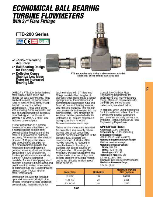
F-60FU ±0.5% of Reading Accuracy U B all Bearing Design for Economy U D eflector Cones Stabilize Low Mass Rotor for Increased Bearing LifeECONOMICAL BALL BEARING TURBINE FLOWMETERSWith 37° Flare FittingsFTB-200 SeriesFTB-201, turbine only. Mating 2-wire connector included(not shown) Shown smaller than actual size.SpECIFICATIonSAccuracy: ±0.5% of reading Repeatability: ±0.1% of reading Temperature Range:-268 to 232°C (-450 to 450°F)Maximum Intermittent overrange: 150% of maximum range Materials of Construction: Body: 304 SSRotor: 17-4 PH SS Bearings: 440C SSInstallation Kits: 340 SS, 1.7 mm (0.065") thickElectrical: Two-wire connector included Maximum pressure Drop: 0.34 bar (5 psi)Omega’s FTB-200 Series turbine meters have male flared-endfittings for easy connections. They are built to meet the performance requirements of mS33656, though they do not carry a militaryspecification. These units come with a mating 2-wire connector and can be supplied with the integrally mounted signal conditioner to provide 4 to 20 ma, 0 to 5V, and factored pulse outputs.Proper application of a turbine flowmeter requires that there be a suitable piping section both downstream and upstream of the meter if it is to achieve optimum accuracy. Whereas an inlet straight pipe run of 10 pipe diameters and an outlet straight pipe run of 5 pipe diameters provide the necessary flow conditioning ingeneral, some applications require an upstream flow straightener. Such applications include custody transfer. a flow straightenerconsists of a section of piping which contains a suitably dimensioned and positioned thin walled tube cluster to eliminate fluid swirl. (See drawing on next page: Typical turbine meter installation).Installation kits with the required up and downstream straight pipe lengths for proper turbine operation are available. Installation kits forturbine meters with 37º flare end fittings consist of two lengths ofstainless steel tubing cut to a length appropriate for the upstream and downstream straight pipe runs and flared at one end. mating sleeves and nuts are included. The kits can be conveniently butt-welded into the piping system. Flow straightening sections may be provided with the installation kit. Kits are available in tubing sizes from ½ to 2½".See accessories chart on next page.These turbine meters are intended for clean fluid service only; where there is any doubt concerningpossible particulate impurities in the process fluid, strainers are recommended. a strainer/filter may be required to reduce the potential hazard of fouling or damage that can be caused by foreign matter. Pipe rouge, the extremely fine rust which develops on the inside of some piping, is a serious problem for turbine meters, due to the difficulty in filtering outthese particles.Consult the Omega Flow engineering Department for applications that may entail pipe rouge. minimum requirements for the FTB-200 Series turbine meters are, see chart below.In addition, when using these units for fluids with viscosities other than 1 centistoke special calibrations and universal viscosity curves are available—consult Omega’S Flow engineering Department.F-61FTB-200 Series turbine with signal conditioner scaled and installed, choose system part number from the NIST certification is for turbine meters, signal conditioners do not come with a NIST traceable certificate.* For details on the signal conditioners, visit us online.Ordering Examples: SYS/FTB-202/FLSC-C1-LIQ, scaled and assembled system includes 0.75 to 7.5 GPM range turbine flow meter and loop powered signal conditioner with 4 to 20 mA output.SYS/FTB-206/FLSC-C3-AL-LIQ, scaled and assembled system includes 4 to 60 GPM range turbine flowmeter and DC powered signal conditioner with 4 to 20 mA output and alarm.。
- 1、下载文档前请自行甄别文档内容的完整性,平台不提供额外的编辑、内容补充、找答案等附加服务。
- 2、"仅部分预览"的文档,不可在线预览部分如存在完整性等问题,可反馈申请退款(可完整预览的文档不适用该条件!)。
- 3、如文档侵犯您的权益,请联系客服反馈,我们会尽快为您处理(人工客服工作时间:9:00-18:30)。
8 维修....................................................................24 2
1 保修和义务 原则上, 产品的供给要符合我们销售和运送的通用条款。这些条款已经在签订合同时提供给 最新的版本。
保修: - 施密特张力仪表保修期为12个月. 易磨损配件,电子元器件和测量弹簧片不在保修范围之内。 由以下原因引起的仪表外观损伤或财产损失施密特公司不负责保修和承担任何责任
该装置绝不能在爆炸性危险气体中使用,也绝不能接触腐蚀性物质。
1.8 版权 本使用说明书的版权归HANS SCHMIDT & Co GmbH公司所有。
使用说明书仅供使用公司及操作人员使用。 使用说明书包含的所有内容未经HANS SCHMIDT & Co GmbH 允许不得被引用或 复制,违反者
1.9 EU - 确认和WEEE注册声明 符合EC Directive 89 / 336 / EEC (93 / 68 / EEC)
2 可选型号................................................................5 2.1 规格........ .......................................................5 2.2 可选配件........................................................... 6 2.3 发货内容....... ....................................................6 2.4 开封............................................................... 6
使用范围亦包括: - 遵守使用说明书中的所有注意事项并执行所有检查与保养工作。
1.7 操作该装置的危险
该装置的设计符合人工环境方面的规定及已被证明的安全标准。尽管如此, 它的使用仍可以对使用人员或第三者造成严重或致命的伤害,并且有可能 损害该装置或其它材料。 该装置只能用于: - 在符合安全的条件下按其用途使用。 - 当出现可能损害安全的故障时必须马上矫正。 - 必须使用EC Directive 90/686/EEC规定的个人劳动保护用品。
- 定期考察操作人员的工作方法与责任心。
1.3 使用人员的责任 所有使用该装置的人在开始工作前应同意履行下列义务:
- 遵守工业安全与防止事故的基本规定。 - 阅读使用说明书中安全与警告事项的章节并签字确认已理解了它们。
3
1.4 常规安全措施 使用该装置时要随身携带本使用说明书。 除了使用说明书,操作人员也必须遵守当地有效的关于防止事故和保护环境的规定。
4 服务和维护............................................................. 19 4.1 导轮 ............................................................ 19 4.2 更换导轮....................... .................................... 20
说明中所指方向一般表示从该装置正面看到的方向,如前、后、左、右。
1.2 用户的责任 按照EC Directive 89/655/EEC的规定,用户只能允许满足下列条件的人员使用该装置:
- 熟悉工业安全与防止事故的基本规定,并且已经接受过使用该装置的培训。
- 已阅读并理解了本使用说明书中安全与警告事项的章节并签字确认。
*测量头宽度 mm 24 24 24 24 24 24
采用运动纱线标定 100 m/min
PA: 0.20 mm Ø PA: 0.20 mm Ø PA: 0.20 mm Ø PA: 0.20 mm Ø PA: 0.20 mm Ø PA: 0.20 mm Ø
3 初始设置和操作流程.................. ................................... 6 3.1 开始测量前的注意事项............................................... 6 3.1.1 ID 标签, CE 标示, 标定标签....................................6 3.1.2 移除导线器................ ................................... 7 3.1.3 安装导线器....................................................7 3.2 操作单元......... ..................................................8 3.3 电池插入和更换 .................................................... 8 3.3.1 开机......................................................... 8 3.3.2 关机......................................................... 8 3.3.3 转换显示方向................................................. 9 3.3.4 选择测量单位............. ....................................9 3.3.5 测量位置的零点设定(自动清零)..................................10 3.4 操作流程.......... .................................................10 3.4.1 打开阻尼模式............. .................................... 11 3.4.2 改变阻尼参数.............. ................................... 11 3.5 储存测量值.............. ...........................................12 3.5.1 查看存储张力值................................................ 12 3.5.2 清除仪表存储信息............................................. 13 3.5.3 记忆功能保持键....... ........................................ 13 3.6 错误信息...... .....................................................14 3.7 静态测量精度验证.................... ...............................14 3.8 仪表动态标定....................................................... 15 3.9 仪表静态标定............. ..........................................15 3.9.1 标定过程中的错误信息.......... ............................... 18 3.9.2 回复出厂标定..................................................18
Tension Meter
ET Series Model ETB
ETPB
Edition
ET 01.0.E
操作指南
Valid as :of01.06.2006• Please keep the manual for future r!eference
内容 1 保修及责任........... .................................................. 3
- 操作不当或滥用仪表. - 不正确的安装, 调试, 操作和保养
- 在任何安全装置有缺陷、任何安保警告没有被合理安装或失效时,使用该装置。
- 没有遵守本使用说明书中关于运输、存放、安装、调试、操作、维护和设置的注意事项。