FTM-9823T-CGHG中文资料
FTTBONU设备学习资料要点

工程名第x册单项工程名目录1 设备主要技术指标 (1)1.1中兴ONU:9806H (1)1.1.1接口功能 (1)1.1.2技术指标和参数 (1)1.1.3物理性能 (2)1.2中兴ONU:F820 (3)1.2.1接口 (3)1.2.2技术指标和参数 (3)1.2.3物理规格 (6)1.3华为ONU: MA5616 (6)1.3.1设备参数 (6)1.3.2性能与容量 (7)1.3.3业务特性与规格 (8)1.4华为ONU: MA5610 (10)1.4.1设备参数 (10)1.4.2性能与容量 (11)1.4.3业务特性与规格 (11)1.5新邮通 ONU: T233 (14)1.5.1产品简介: (14)1.5.2产品特点: (14)1.5.3产品特性: (15)1设备主要技术指标1.1中兴 ONU:9806HZXDSL9806是一款提供xDSL用户线路的调制解调、多种宽带业务综合接入等功能的小容量的一体化设备,支持EPONt行。
可以满配4块用户板,最多支持96路ADSL2/2+Over POTS用户或64路VDSL2用户接入。
适合ONU节点、园区、企业等小容量接入的应用1.1.1接口功能线路侧:1个标准PONH( SC/PC用户侧:96个ADSL/ADSL2接口,或64个VDSL2用户接口1.1.2技术指标和参数数据传输速率线路端(EPON: 1.25Gbps (上下行对称)线路端(GPON :上行 1.244Gbps,下行 2.488Gbps用户端接口: 10/100Mbps自适应传输距离链路距离0〜20Km( MAX)传输波长接收中心波长:1490nm发送中心波长:1310 nm业务功能支持EPON GPON t行接口支持《EPONS备互通性要求》,满足所有扩展 OAM功能支持上电自动注册支持上行业务的加密和解密,支持 churning和AES128两种加密方式。
支持 Dying Gasp支持事件自动上告功能DSLAM fe 能支持协议:802.1Q VLAN SVLAN LINK AGGREGATION, VBAS, DHCP OP82PPOE, SNTP 组播控制:IGMPSNOOPINGGMPPROXYIGMPROUTER组播 VLAN CAC,PRW,CDR, SMS 管理,组播频道套餐,组播快速离开,组播预加入,端口组播带宽检测,组播带宽限制,组播业务暂停和恢复等;二层业务:标准L2交换,L2隔离/互通,MAC地址白/黑名单,IP绑定,MAC地址数目限制,MAC地址防欺骗,广播及洪泛包抑制, MAC地址统计/反查,静态MAC用户端口环回检测,以太网端口输出速率限制等;QoS功能:用户端口支持4队列,支持SP/WRR队列调度,支持基于端口 /pvc端口的优先级设置和remarking,支持流分类,支持pvc限速,支持端口优先级信任等;系统安全保护:网管通道ACL,网管通道风暴控制,登陆用户/密码权限管理,DHCP SNOOPING, DHCP SOURCE GUARD, DHCP/IGMP rate IjmSHH f 理,管理用户的远程认证等;系统调试及诊断:内存使用检测/告警,CPU占有率检测/告警,LOG日志,系统 HISTORY3志,系统死机文件,系统自检,端口环回测试,modemi f理,SELT/DELT等;性能统计:ADSL2/2+生能统计,VDSL2性能统计,以太网端口性能统计等;网管支持远程管理支持本地管理支持SNMP1.1.3物理性能功耗:<150W(满配置)尺寸:19 英寸 2U高,88.1mn K 482.6mn K 240mm(高X宽X深)工作温度:-5C〜45E工作湿度:5%〜95%重量:8.5KG供电:220V AC/-48V DC安装方式:机架1.2中兴 ONU:F820ZXA10F820主要用于FTTB/FTT0应用,提供大客户、专线用户以及多用户的接入,提供以太网和TDM(E1)业务以及VOIP业务接入,支持EPON/GPO上联,提供PON D 上联保护。
派克精密流体微型泵说明书
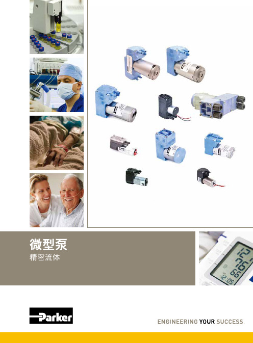
您与运动和控制技术领域的先行者合作,就是希望促进您的业务发展和全球的发展。
从微型电磁阀到高集成型自动化系统,我们的产品对于用于药物研发和病原体检测的救生医疗设备和科学仪器至关重要。
并且对于缩短上市时间和降低总体拥有成本也十分关键。
因此,请与派克合作,准备改变这一切吧!/precisionfluidics 1 603 595-1500目录页T2-05Helix124高效和紧凑型 13.5mm 宽泵 – 高达 800 mLPM高压泵 – 超过5.5 LPM 和高达100 PSI 的压力T2-0320高性能与尺寸比率泵 – 高达2.5 LPMLTC 系列76液体系列传送泵 – 高达 650 mLPMEZ 底座92振动隔离安装系统小型活塞泵(空气)微型泵(空气/气体)微型泵(液体)T2-0494超紧凑型、高效泵 – 高达 7.5LPMBTC-IIS 系列62应用广泛的多功能双头泵系列产品 – 高达 11 LPMBTC 系列52应用广泛的多功能泵系列产品 – 高达6 LPMLTC-IIS 系列84液体系列双头传送泵 – 高达1.5 LPMCTS 系列BTX-Connect 2836高性能紧凑型 20 mm 宽泵 – 高达 2.5 LPM多功能双头和单头泵系列,适合多种应用-高达10 LPMTTC 系列74紧凑、高效、低压泵 – 高达 6 LPMTTC-IIS 系列84紧凑、高效、低压双头泵 - 高达 11 LPM附件4Helix 微型高压泵高达100 PSI (6.9 bar)压力Parker Helix 是一款紧凑型高压泵,旨在实现小型即时临床护理仪器。
Helix 可在挑战性的高海拔环境和无法使用外部压缩空气的应用中实现高压操作。
Helix 泵可提供5.5 LPM 以上的流量和高达100 PSI (6.9 bar)的压力,为性能至关重要且空间有限的台式诊断设备提供了出色的解决方案。
• 集成了用于卸荷的X 阀,可实现高压重启• 内部飞轮可在高压下低速运行• 无油活塞• 简单的安装特性• 带有推入式接头的快速流体连接• 符合RoHS 指令和REACH 标准产品特性• 液上空气• 气动驱动•微流控芯片• 即时临床护理检验• 分子诊断• 核酸纯化•基因组学典型应用典型市场产品规格物理特性电子5微型隔Helix 微型高压泵典型流量曲线• 曲线展示了0.080"偏移泵的流量性能• 使用5.0 Vdc 控制输入时,泵将以大约4400 RPM 的转速和高达8.5 LPM的流量的状态运行,但不建议连续工作。
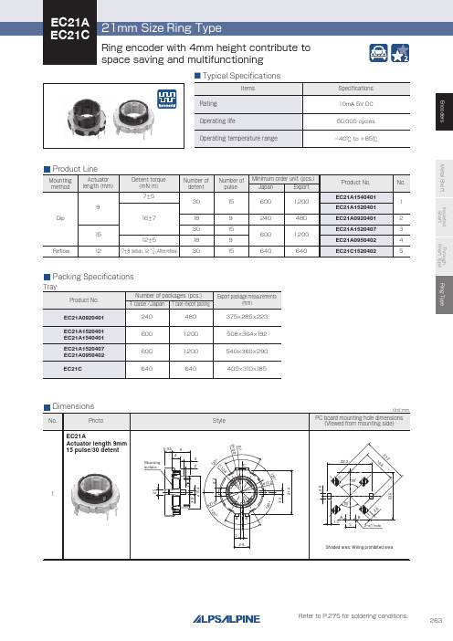
263系列金属螺杆尖耐抗电尖耐抗电尖通螺杆类型环形编码器说明书
Through shaft type
Horizontal
Horizontal
—
12/12
12/24 12/12
9/18 15/30
Ring type
— 15/30
Features
W
Dimensions (mm)
D
H
Operating temperature range
Operating life Automotive use Life cycle (availability)
300V AC for 1minute or 360V AC for 2s
300V AC for 1minute or 360V AC for 1s
—
7±5mN・m 12±5mN・m 16±7mN・m
—
17±8mN・m(Initial) 12+− 74mN・m(After reflow)
100N
Shaft configuration
1
Style
5-3.5 9
4 Mounting surface
3 2
120°
ø21.6
C ø12.2
AB 1
2-8
120°
0.7
2-10.4 120°
Unit:mm
PC board mounting hole dimensions (Viewed from mounting side)
22.3
3
˃˃
˃ $ ˃ $
˃˃
"# "#
EC21A Actuator length 15mm 9 pulse/18 detent
PM9820酚醛模塑料物质安全资料表MSDS
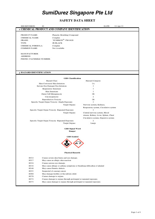
SDS REVISION:01DATE:12-Apr-111CHEMICAL PRODUCT AND COMPANY IDENTIFICATIONPRODUCT NAME:CHEMICAL NAME:GRADE:TYPE:CHEMICAL FORMULA:COMMON NAME:MANUFACTURER:ADDRESS:Phenolic Moulding Compound Complex"SUMIKON ®" PM-9820JR BLACK Complex Not AvailablePHONE / FACSIMILE NUMBER:2Central nervous system, BloodMay cause damage to organs through prolonged or repeated exposure.H317May cause an allegic skin reaction H334May cause allergy or asthma symptoms or breathing difficulties if inhaled Causes severe skin burns and eye damage.Causes serious eye damage.May cause Genetic defects.Hazard ClassSkin Corrosion/ Skin Irritation Target Organs: Nervous system, Kidneys,11B Respiratory system, Circulative systemServere Eye Damage/ Eye IrritationGerm Cell MutagenicityCarcinogenicity Reproductive ToxicitySpecific Target Organ Toxicity -Single ExposureRespiratory Sensitizer 1Skin Sensitizer 11A 11B 22Specific Target Organ Toxicity -Repeated Exposure1Target Organs:Specific Target Organ Toxicity -Repeated ExposureH351H360H370H372LungsSuspected of causing cancer.May damage ferillity or the unborn child.Causes damage to organs.HAZARD IDENTIFICATIONGHS ClassificationH314H318Physical HazardsHarzard Categorystream, Kidney, Liver, Spleen, Chest Circulative system, Digestive systemTarget Organs:H340 GHS Signal WordDanger GHS SymbolCauses damage to organs through prolonged or repeated exposure.SumiDurez Singapore Pte LtdSAFETY DATA SHEETH373IF SKIN IRRIATION OR RASH OCCURS : Get medical advice/ attention Wash contaminated clothing before reuse3COMPOSITION / INFORMATION ON INGREDIENTS4FIRST AID MEASURESEYE:Don't Let The Victim Rub His/Her Eyes. Flush Eyes With Large Amounts Of Clean Water Immediately And Continuously For At Least 15 minutes.IF IRRITATION PERSISTS, GET MEDICAL ATTENTION.SKIN:Wash The Affected Area Under Running Water With Soap.INHALATION:Remove To Fresh Air. If Not Breathing, Give Mouth Resuscitation. If Breathing Is Difficult,Given Oxygen.GET MEDICAL ATTENTION.INGESTION:Rinse Mouth With Water. Drink Large Quantities Of Water, And Then Induce Vomiting By Having Patient Tickle Back Of Throat With Finger.NOTES TO Treat Symptomatically.PHYSICIANS:Treatment May Vary With Condition Of Victim And Specifics Of Incident.Carbon BlackCalcium Hydroxide Cotton flock Zinc Borate Calcium StearateComponents Phenolic Resin Wood DustMagnesium Hydroxide P280Wear protective gloves/ protective clothing/ eye protection/ face protection P285In case of inadequate ventilation wear respiratory protection1333-86-40.1 - 1Wash thoroughly after handlingDo not eat, drink or smoke when using this productContaminated work clothing should not be allowed out of the workplace - 2.5 - 109003-35-4-1309-42-8P270P272 international regulationsP307 + P311Immediately call a POISON CENTER or doctor/physician.IF ON SKIN (or hair): Remove/Take off immediately all contaminated clothing .P301 + P330 + P331If SWALLOWED : Rinse mouth. Do not induce vomiting.IF IN EYES : Rinse cautiously with water for several minutes. Remove contact lenses,P310P304 + P340P305 + P351 + P338P333 + P313P363P201Obtain special instruction before use.Do not handle until all safety precaution have been P314Response precautionary StatementsPrevention Precautionary StatementsDo not breathe dust/ fume/ gas/ mist/ vapour/ spray 40 - 60P501P202P260P264Disposal Precautionary StatementsRinse skin with water/shower.IF INHALED : Remove victim to fresh air and keep at rest in a position comfortablefor breathing.IF EXPOSED : Call a POSION CENTER or doctor/physician.Phenol 1305-62-01 - 2.5(CAS No.)Percentage (%)P405P303 + P361 + P353Get medical advice/attention if you feel unwell.2.5 - 10108-95-21332-07-61592-23-0 1 - 2.5Storage Precautionary Statementsif present and easy to do. Continue rinsing.2.5 - 10Store locked up20 - 4010 - 20Dispose of contents/container: In accordance with local/ regional/ national/5FIRE FIGHTING MEASURESFLAMMABLE PROPERTIES:FLASH POINT (°C/°F):Not Determined (METHOD USED: Not applicable )AUTO IGNITION (°C/°F):Not Determined TEMPERATURE (°C/°F):Not DeterminedFLAMMABLE LIMITS:Lower FL: Not DeterminedUpper FL: Not DeterminedEXTINGUISHING MEDIA:Use Water, Dry Chemical, Halon, Alcohol Foam, Carbon Dioxide Or Sand.FIRE & EXPLOSION HAZARDS:Dense Smoke Emitted When Burned Without Sufficient Oxygen And Hazardous (NORMAL)Decomposition Products Are Carbon Dioxide (CO 2) And Some Carbon Monoxide (CO).FIRE & EXPLOSION HAZARDS:Explosive Hazard. Organic Dust Can Be Explosive When Ideal Conditions Of (UNUSUAL)Concentration, Humidity And Source Are Met.PROTECTION (EQUIPMENT)Wear Full Bunker Gear Including A Positive Pressure Self-Contained BreathingOF FIREFIGHTERS:Apparatus Approved By MSHA / NIOSH In Any Closed Space. Do Not Inhale Gases.6ACCIDENTAL RELEASE MEASURESCarefully Sweep Up Or Vacuum Spills And Place It In A Waste Container With Proper Personal Protective Equipment.Avoid Raising Dust. Vacuum Cleaning Is Preferred So As To Minimise Dust.7HANDLING AND STORAGEHANDLING:Keep Container Closed. When Handling, Avoid Eye Contact And Breathing Dusts If e Good House Keeping Practices To Prevent The Accumulation Of Dust.After Using This Material, Wash Hands.SPECIAL MIXING:Resin Will Polymerise Exothermically At Temperature In Excess Of 40°C STORAGE:Store In Cool And Dry Place To Avoid Effects Of Heat And Moisture.Exposure To High Temperature And/Or Moisture Causes Resin Agglomeration.8EXPOSURE CONTROLS / PERSONAL PROTECTIONppm mg/m 3ppm mg/m 3-5--519--- 3.5---5-10ENGINEERING CONTROLS:Provide General And/Or Local Exhaust Ventilation To Control AirborneLevels Below The Exposure Guidelines.PERSONAL PROTECTIVE EQUIPMENT (PPE):RESPIRATORY PROTECTION:Wear A Safety Mask To Protect From Dust.EYE PROTECTION:Wear Safety Glasses With Side Shields Or Goggles.SKIN / BODY PROTECTION:Wear Clean Body-Covering Clothing. Wear Cloth Or Rubber Gloves.OTHER PROTECTIVE EQUIPMENT:Eye Wash Facility Should Be In Close Proximity (ANSI Z358.1 - 1981).9PHYSICAL AND CHEMICAL PROPERTIESAPPEARANCE PHYSICAL STATE:Solid.PHYSICAL APPREARANCE:Granular Solid COLOR:BlackWood Dust (soft)Phenol Carbon Black Permissible Exposure Limit (PEL)Long Term Short TermSINGAPORE OCCUPATIONAL EXPOSURE LIMITS:Calcium HydroxideComponentsODOR:Slight Phenolic Odor.pH Value:Not Applicable.MELTING POINT:Not Applicable.BOILING POINT:Not Applicable.FLASH POINT:Not Applicable.AUTO IGNITION POINT:Not Applicable.LOWER FLAMMABILITY LIMIT:Not Applicable.UPPER FLAMMABILITY LIMIT:Not Applicable.VAPOR PRESSURE:Not Applicable.VAPOR DENSITY:Not Applicable.SPECIFIC GRAVITY: 1.4 - 1.5SOLUBILITY IN WATER:Not Applicable.PARTITION COEFFICIENT:Not ApplicableDECOMPOSITION TEMPERATURE:Not Applicable10STABILITY AND REACTIVITYCHEMICAL STABILITY (CONDITION TO AVOID):Avoid Exposing To High Temperature And/Or Moisture And Dust Buildup In The Manufacturing Areas.INCOMPATIBILITY (SPECIFIC MATERIALS TO AVOID):Avoid Acids And/Or Alkaline.HAZARDOUS DECOMPOSITION PRODUCTS:Carbon Dioxide (CO2) And Some Carbon Monoxide (CO), Traces Of Phenol Vapour And Ammonia Gas.HAZARDOUS POLYMERISATION:Will Not Occur.11TOXICOLOGICAL INFORMATIONRoutes of Exposure Inhalation, Ingestion (Swallowing), Skin or Eye ExposureAcute ToxicityPhenol ACUTE Ingestion LD50 (Rat):317 mg/kg(CAS No.: 108-95-2)ACUTE Skin Contact LD50 (Rat):669 mg/kgACUTE Skin Contact LD50 (Rabbit):850 mg/kgCalcium Hydroxide ACUTE Ingestion LD50 (Rat):7340 mg/kg(CAS No.: 1305-62-0)Magnesium Hydroxide ACUTE Ingestion LD50 (Rat):8500 mg/kg(CAS No.: 1309-42-8)Skin Corrosion/ Irritation:Causes severe skin burnsSerious Eye Damage/ Irritation:Causes severe skin burns and eye damage. Causes serious eye damageRespiratory Sensitisation:No DataSkin Sensitisation:Causes sever skin burnsGerm Cell Mutagenicity:May Cause Genetic Defects. May Induce Heritable MutationCarcinogenicity:Suspected of causing cancerIARC:Substance ClassificationWood Dust(CAS - )Group 1 Carcinogenic to humansCarbon Black(CAS 1333-86-4)Group 2B Possibly carcinogenic to humansPhenol(CAS 108-95-2)Group 3 Not classifiable as to its carcinogenicity tohumansReproductive Toxicity May cause infertitly or harm to the unborn childSpecific Target Organ ToxicitySingle Exposure No DataRepeated Exposure No DataAspiration Hazard No DataMetabolism Long term exposure will lead to side effects12ECOLOGICAL INFORMATIONEcological StatisticsSubstance Test resultsPhenol(CAS No.108-95-2)LC50 Medaka, high-eyes (Oryzias latipes):23.4 - 36.6 mg/l 96 h Calcium Hydroxide(CAS No.1305-62-0)LC50 Zambezi barbel (Clarias gariepinus):33.8844 mg/l 96 h Eco-Toxicity Contains substances which is harmful to the environmentPersistence and Degradability No DataBio Accumulative Potential No DataMobility in Soil No DataOther Adverse Effects No Data13DISPOSAL CONSIDERATIONSDispose Of Materials To Be In Accordance with Local/ Regional/ National/ Internation Regulations14TRANSPORT INFORMATIONUN number:NoneUN proper shipping name:Not AllocatedTransport Hazard Class:Not Classified as hazardous for TransportPacking Group:Not AllocatedMarine Pollutant:Not AllocatedTransport in Bulk:Not AllocatedSpecial Precautions:None15REGULATORY INFORMATIONGeneralSingapore's Workplace Safety and Health (General Provisions) Regulations 2006Singapore Standards:-CP 12:2001 Part 1-CP 98:2003-SS 152:2003-SS 286:1984 Part 1 to Part 5International StandardsIARC: International Agency for Research on Cancer16OTHER INFORMATIONReferencesSingapore's Workplace Safety and Health (General Provisions) Regulations 2006Singapore Standards:-CP 12:2001 Part 1-CP 98:2003-SS 152:2003-SS 286:1984 Part 1 to Part 5International StandardsIARC: International Agency for Research on CancerISSUED BY:SUMIDUREZ SINGAPORE PTE LTD DEPARTMENT:EH&SThe Information Presented Herein, While Not Guaranteed, Was Prepared By Competent Technical Personnel For Your Reference And Is True And Accurate To The Best Of Our Knowledge. It Is Given In Good Faith. No Warranty Or Guaranty, Express Or Implied, Is Made Regarding Performance, Stability Or Otherwise. This Information Is Not Intended To Be For All - Inclusive As To The Manner And Conditions Of Use, Handling And Storage. Following Of Safety Procedures During Handling And Use Remains The Responsibility Of The Recipient / Customer.。
Modicon TM3TI8T产品数据手册说明书
i s c l ai m e r : T h i s d o c u m e n t a t i o n i s n o t i n t e n d e d a s a s u b s t i t u t e f o r a n d i s n o t t o b e u s e d f o r d e t e r m i n i n g s u i t a b i l i t y o r r e l i a b i l i t y o f t h e s e p r o d u c t s f o r s p e c i f i c u s e r a p p l i c a t i o n sMainRange of productModicon TM3Product or component typeAnalog input module Range compatibility Modicon M221Modicon M251Modicon M241Analogue input number 8Analogue input typeThermocouple, analogue input range: - 200...1000 °C with thermocouple JThermocouple, analogue input range: - 200...1300 °C with thermocouple KThermocouple, analogue input range: 0...1760 °C with thermocouple RThermocouple, analogue input range: 0...1760 °C with thermocouple SThermocouple, analogue input range: 0...1820 °C with thermocouple BThermocouple, analogue input range: - 200...400 °C with thermocouple TThermocouple, analogue input range: - 200...1300 °C with thermocouple NThermocouple, analogue input range: - 200...800 °C with thermocouple EThermocouple, analogue input range: 0...2315 °C with thermocouple CNTC 10k thermistor, analogue input range: -90...150 °CPTC thermistor, analogue input range: 100...10000 OhmThermocouple, analogue input range: - 200...1000 °C ComplementaryAnalogue input resolution15 bits + sign 16 bits Input impedance >= 1 MOhm temperature probe>= 1 MOhm thermistor>= 1 MOhm thermocoupleLSB value 0.1 °C with NTC probe1 Ohm with PTC/NTC probe0.1 °C thermocoupleConversion time 100 ms + 100 ms per channel + 1 controller cycle timeSampling duration 100 msAbsolute accuracy error +/- 1 % of full scale+/- 6 °C at 0...200 °C for thermocouple R+/- 6 °C at 0...200 °C for thermocouple S+/- 0.4 % of full scale at <= 0 °C for thermocouple K+/- 0.4 % of full scale at <= 0 °C for thermocouple J+/- 0.4 % of full scale at <= 0 °C for thermocouple ECurrent consumption30 mA at 24 V DC via external supply45 mA at 5 V DC via bus connector40 mA at 5 V DC via bus connectorLocal signalling 1 LED green for PWRElectrical connection10 x 1.5 mm² removable screw terminal block with pitch 3.81 mm adjustment for inputs and supply10 x 1.5 mm² removable screw terminal block with pitch 3.81 mm adjustment for inputs Insulation500 V AC between input and internal logic1500 V AC between input and supplyMarking CESurge withstand 1 kV for power supply with common mode protection conforming to EN/IEC 61000-4-50.5 kV for power supply with differential mode protection conforming to EN/IEC 61000-4-51 kV for input with common mode protection conforming to EN/IEC 61000-4-5Mounting support Top hat type TH35-15 rail conforming to IEC 60715Top hat type TH35-7.5 rail conforming to IEC 60715Plate or panel with fixing kitHeight90 mmDepth70 mmWidth23.6 mmProduct weight0.11 kgEnvironmentStandards EN/IEC 61131-2EN/IEC 61010-2-201Resistance to electrostatic discharge 4 kV on contact conforming to EN/IEC 61000-4-28 kV in air conforming to EN/IEC 61000-4-2Resistance to electromagnetic fields10 V/m at 80 MHz...1 GHz conforming to EN/IEC 61000-4-33 V/m at 1.4 GHz...2 GHz conforming to EN/IEC 61000-4-31 V/m at2 GHz...3 GHz conforming to EN/IEC 61000-4-3Resistance to magnetic fields30 A/m at 50...60 Hz conforming to EN/IEC 61000-4-8Resistance to fast transients 1 kV I/O conforming to EN/IEC 61000-4-4Resistance to conducted disturbances, induced by radio frequency fields 10 V at 0.15...80 MHz conforming to EN/IEC 61000-4-63 V at spot frequency (2, 3, 4, 6.2, 8.2, 12.6, 16.5, 18.8, 22, 25 MHz) conforming to Marine specification (LR, ABS, DNV, GL)Electromagnetic emission Radiated emissions, test level: 40 dBμV/m QP class A (10 m at 30...230 MHz) conforming to EN/IEC55011Radiated emissions, test level: 47 dBμV/m QP class A (10 m at 230 MHz...1 GHz) conforming to EN/IEC 55011Immunity to microbreaks10 msAmbient air temperature for operation-10...55 °C (horizontal installation)-10...35 °C (vertical installation)Ambient air temperature for storage-25...70 °CRelative humidity10...95 % without condensation in operation10...95 % without condensation in storageIP degree of protection IP20Pollution degree2Operating altitude0...2000 mStorage altitude0...3000 mVibration resistance 3.5 mm at 5...8.4 Hz with DIN rail mounting support3 gn at 8.4...150 Hz with DIN rail mounting supportProduct environmental Product end of life instructionsAvailableEnd of life manual(*)8.5 mm/0.33 in when the clamp is pulled out.Incorrect Mounting(1)Install a mounting strip Mounting Hole LayoutWiring Diagram (Thermocouple Input Type)(*)Type T fuse (1)ThermocoupleWiring Diagram (Temperature Probe Input Type)(*)Type T fuse。
RTHG-G互感器综合测试仪使用说明书
九、大容量 FLASH 存储:可保存 1000 组试验数据,掉电不丢失。 十、 、支持 U 盘实现无限量存储,可通过标准 PC 进行读取或生成检测报告
支持 U 盘转存,实现无限量存储。并且可与电脑连接,用我公司开发的数据分析软件, 不仅可直观地辨别数据和曲线,并能自动生成检测报告。方便工作人员,提高工作效率。
பைடு நூலகம்
2
RTHG-G 互感器综合测试仪
武汉锐拓普电力设备有限公司
概述
RTHG-G 互感器综合测试仪主要用于现场检测 CT、PT 的伏安特性、变比、 极性、 5%10%的误差曲线、 交流耐压、 二次负荷、 退磁等, 单机输出电压可达 2500V, 峰值电流达到 15A。实验时仅需设定测试电压/电流值,不需要设置步长,设备便 能够自动升压/升流,并将互感器的伏安特性曲线或变比、极性等实验结果快速显 示出来,支持数据上传和现场打印,不但省去手动调压、人工记录、描曲线等繁 琐劳动, 还能通过 USB 接口转存测试数据,进行编辑保存或打印。操作简单方便, 提高工作效率,是一种性价比较高的高科技产品。
3.1、CT 伏安特性测试: 1) 参数设置: (图 2)
编号:(00~99)、 组号:(0~9); 相序:(A/B/C); 日期:(年/月/日) 上述 4 条设置项将在保存时保存为索引信息方便用户查询。
7
RTHG-G 互感器综合测试仪
武汉锐拓普电力设备有限公司
2) 开始试验:
接线图见(图 4) ,测试仪的 A、X 为电压输出端,试验时将 A、X 分别接互感器 的 S1、S2(互感器的所有端子的连线都应甩开) 。接线无误后,合上功率开关,参数设置后, 按“开始” 键后,即开始测试, (见图 5) 。 试验时,光标在“停止”选项上,并不停闪烁,测试仪开始自动升压、升流,当测试 仪检测完毕后,试验结束并描绘出伏安特性曲线图(如图 6) 。
托利多吊钩秤说明书
5.1. 开箱检查 .............................................................................................................................................................. 12
5. 使用准备 ................................................................................................................................................................. 12
3.1. 产品命名及型号 .................................................................................................................................................... 6
6.7. 累计调显 .............................................................................................................................................................. 15
6.4. 清皮 ...................................................................................................................................................................... 13
淼田电子有限公司LQG15HH系列芯片电感说明书
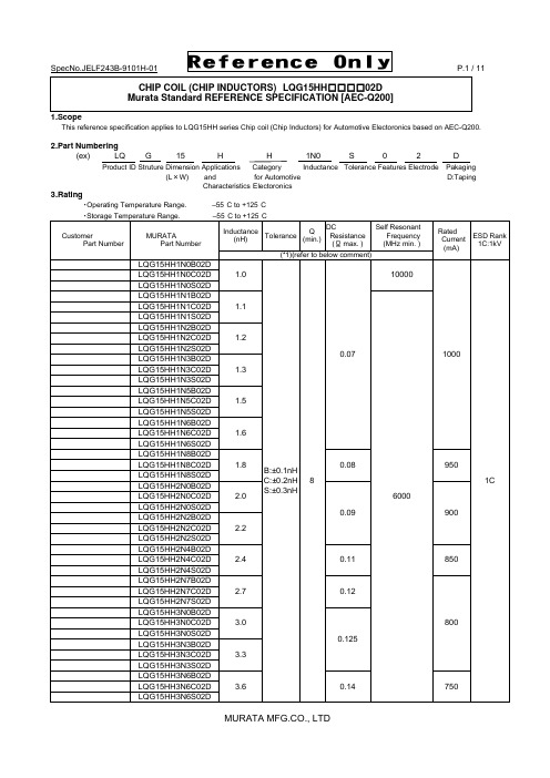
SpecNo.JELF243B-9101H-01 P.1 / 11Reference OnlyCHIP COIL (CHIP INDUCTORS) LQG15HH □□□□02DMurata Standard REFERENCE SPECIFICATION [AEC-Q200]1.ScopeThis reference specification applies to LQG15HH series Chip coil (Chip Inductors) for Automotive Electoronics based on AEC-Q200.2.Part Numbering(ex) LQ G 15 H H 1N0 S 0 2 DProduct ID Struture Dimension Applications Category Inductance Tolerance Features Electrode Pakaging(L ×W) and for Automotive D:TapingCharacteristics Electoronics3.Rating・Operating Temperature Range. –55°C to +125°C ・Storage Temperature Range. –55°C to +125°CCustomer Part Number MURATAPart NumberInductance (nH) ToleranceQ(min.)DC Resistance (Ω max. ) Self ResonantFrequency (MHz min. )Rated Current (mA)ESD Rank 1C:1kV(*1)(refer to below comment)LQG15HH1N0B02D1.0B:±0.1nHC:±0.2nH S:±0.3nH8 0.07 10000 10001CLQG15HH1N0C02D LQG15HH1N0S02D LQG15HH1N1B02D1.1 6000 LQG15HH1N1C02DLQG15HH1N1S02D LQG15HH1N2B02D 1.2 LQG15HH1N2C02D LQG15HH1N2S02DLQG15HH1N3B02D1.3 LQG15HH1N3C02DLQG15HH1N3S02D LQG15HH1N5B02D1.5 LQG15HH1N5C02DLQG15HH1N5S02D LQG15HH1N6B02D 1.6 LQG15HH1N6C02D LQG15HH1N6S02D LQG15HH1N8B02D 1.8 0.08 950LQG15HH1N8C02D LQG15HH1N8S02DLQG15HH2N0B02D2.0 0.09 900LQG15HH2N0C02DLQG15HH2N0S02DLQG15HH2N2B02D 2.2 LQG15HH2N2C02D LQG15HH2N2S02D LQG15HH2N4B02D2.4 0.11 850 LQG15HH2N4C02DLQG15HH2N4S02D LQG15HH2N7B02D 2.7 0.12 800 LQG15HH2N7C02D LQG15HH2N7S02D LQG15HH3N0B02D 3.0 0.125LQG15HH3N0C02D LQG15HH3N0S02DLQG15HH3N3B02D3.3 LQG15HH3N3C02DLQG15HH3N3S02D LQG15HH3N6B02D3.6 0.14 750 LQG15HH3N6C02DLQG15HH3N6S02DCustomer Part Number MURATAPart NumberInductance (nH) ToleranceQ(min.)DC Resistance (Ω max. ) Self ResonantFrequency(MHz min. )RatedCurrent(mA)ESD Rank 1C:1kV(*1)(refer to below comment)LQG15HH3N9B02D3.9 B:±0.1nHC:±0.2nHS:±0.3nH8 0.14 6000 7501CLQG15HH3N9C02DLQG15HH3N9S02DLQG15HH4N3B02D 4.3 LQG15HH4N3C02D LQG15HH4N3S02D LQG15HH4N7B02D 4.7 0.16 700LQG15HH4N7C02D LQG15HH4N7S02DLQG15HH5N1B02D5.1 0.18 5300 650LQG15HH5N1C02DLQG15HH5N1S02DLQG15HH5N6B02D5.6 4500 LQG15HH5N6C02DLQG15HH5N6S02D LQG15HH6N2B02D6.2 0.20 600LQG15HH6N2C02DLQG15HH6N2S02DLQG15HH6N8G02D6.8 G:±2%H:±3%J:±5%0.22 LQG15HH6N8H02DLQG15HH6N8J02D LQG15HH7N5G02D 7.5 0.24 4200 550LQG15HH7N5H02D LQG15HH7N5J02DLQG15HH8N2G02D 8.2 3700 LQG15HH8N2H02D LQG15HH8N2J02DLQG15HH9N1G02D 9.1 0.26 3400500LQG15HH9N1H02D LQG15HH9N1J02DLQG15HH10NG02D10 LQG15HH10NH02D LQG15HH10NJ02D LQG15HH12NG02D12 0.28 3000 LQG15HH12NH02DLQG15HH12NJ02DLQG15HH15NG02D15 0.32 2500 450 LQG15HH15NH02DLQG15HH15NJ02D LQG15HH18NG02D18 0.36 2200 400 LQG15HH18NH02DLQG15HH18NJ02D LQG15HH22NG02D 22 0.42 1900 350 LQG15HH22NH02D LQG15HH22NJ02D LQG15HH27NG02D 27 0.46 1700 LQG15HH27NH02D LQG15HH27NJ02D LQG15HH33NG02D33 0.58 1600 LQG15HH33NH02DLQG15HH33NJ02D LQG15HH39NG02D39 0.65 1200 300 LQG15HH39NH02DLQG15HH39NJ02DCustomer Part Number MURATAPart NumberInductance (nH) Tolerance Q(min.) DC Resistance (Ω max. ) Self Resonant Frequency (MHz min. )Rated Current (mA)ESD Rank 1C:1kV(*1)(refer to below comment)LQG15HH47NG02D 47 G:±2%H:±3%J:±5%8 0.72 1000 3001CLQG15HH47NH02D LQG15HH47NJ02DLQG15HH56NG02D 56 0.82 800 250LQG15HH56NH02D LQG15HH56NJ02DLQG15HH68NG02D68 0.92 LQG15HH68NH02DLQG15HH68NJ02D LQG15HH82NG02D82 1.20 700 200 LQG15HH82NH02DLQG15HH82NJ02D LQG15HHR10G02D100 1.25 600 LQG15HHR10H02DLQG15HHR10J02DLQG15HHR12G02D120 1.30 LQG15HHR12H02DLQG15HHR12J02DLQG15HHR15G02D 150 2.99 550 150LQG15HHR15H02D LQG15HHR15J02DLQG15HHR18G02D 180 3.38 500 LQG15HHR18H02D LQG15HHR18J02D LQG15HHR22G02D 220 3.77 450 120 LQG15HHR22H02D LQG15HHR22J02D LQG15HHR27G02D270 4.94 400 110 LQG15HHR27H02DLQG15HHR27J02D(*1) Standard Testing Conditions《Unless otherwise specified 》 《In case of doubt 》Temperature : Ordinary Temperature / 15°C to 35°C Temperature: 20°C ± 2°CHumidity :Ordinary Humidity / 25%(RH) to 85%(RH) Humidity : 60%(RH) to 70%(RH) Atmospheric Pressure : 86kPa to 106 kPa4. Appearance and Dimensions■Unit Mass (Typical value)6.Q200 Requirement6.1.Performance (based on Table 5 for Magnetics(Inductors / Transformer)AEC-Q200 Rev.D issued June 1. 2010AEC-Q200 Murata Specification / Deviation No Stress TestMethod3 HighTemperatureExposure 1000hours at 125 deg CSet for 24hours at roomtemperature, then measured.Meet Table A after testing.Table A4 TemperatureCycling 1000cycles-40 deg C to +125 deg CSet for 24hours at roomtemperature,thenmeasured.Meet Table A after testing.7 Biased Humidity 1000hours at 85 deg C, 85%RHunpowered.Meet Table A after testing.8 Operational Life Apply 125 deg C 1000hoursSet for 24hours at roomtemperature, then measuredMeet Table A after testing.9 External Visual Visual inspection No abnormalities10 Physical Dimension Meet ITEM 4(Style and Dimensions)No defects12 Resistanceto Solvents PerMIL-STD-202Method 215Not ApplicableAppearance No damageInductanceChange(at 100MHz)Within ±10%AEC-Q200 Murata Specification / Deviation No Stress TestMethod13 Mechanical Shock Per MIL-STD-202Method 213Condition C : 100g’s(0.98N),6ms, Half sine, 12.3ft/sMeet Table A after testing.14 Vibration 5g's(0.049N) for 20 minutes,12cycles each of 3 oritentationsTest from 10-2000Hz.Meet Table A after testing.15 Resistanceto Soldering Heat No-heatingSolder temperature260C+/-5 deg CImmersion time 10sMeet Table A after testing.Pre-heating 150C +/-10 deg C, 60s to 90s17 ESD Per AEC-Q200-002 ESD Rank: refer to the Item3 (Rating).Meet Table A after testing18 Solderbility Per J-STD-002 Method b : Not Applicable90% of the terminations is to be soldered.19 ElectricalCharacterizationMeasured : Inductance No defects20 Flammability Per UL-94 Not Applicable21 Board Flex Epoxy-PCB(1.6mm)Deflection 2mm(min)Holding time 60s Meet Table B after testing.Table BAppearance No damage DCresistanceChangeWithin ±10%22 Terminal Strength Per AEC-Q200-006A force of 17.7Nfor 60s Murata Deviation Request: 5N No defects7.Specification of Packaging(in mm)7.2 Specification of Taping(1) Packing quantity (standard quantity)10,000 pcs. / reel(2) Packing MethodProducts shall be packed in the cavity of the base tape and sealed by top tape and bottom tape.(3) Sprocket holeThe sprocket holes are to the right as the tape is pulled toward the user.(4) Spliced pointBase tape and Top tape has no spliced point.(5) Missing components numberMissing components number within 0.1 % of the number per reel or 1 pc., whichever is greater,andare not continuous. The Specified quantity per reel is kept.0.8m ax.7.3 Pull StrengthTop tape5N min.Bottom tape7.4 Peeling off force of cover tapeSpeed of Peeling off 300mm/min Peeling off force0.1N to 0.6N(minimum value is typical)7.5 Dimensions of Leader-tape,Trailer and ReelThere shall be leader-tape ( top tape and empty tape) and trailer-tape (empty tape) as follows.7.6 Marking for reelCustomer part number, MURATA part number, Inspection number(*1) ,RoHS Marking(*2), Quantity etc ・・・*1) <Expression of Inspection No.> □□ OOOO ⨯⨯⨯(1) (2) (3)(1) Factory Code (2) Date First digit : Year / Last digit of yearSecond digit: Month / Jan. to Sep. → 1 to 9, Oct. to Dec. → O, N, D Third, Fourth digi : Day(3) Serial No.*2) <Expression of RoHS Marking> ROHS – Y (△)(1) (2)(1) RoHS regulation conformity parts. (2) MURATA classification number7.7 Marking for Outside package (corrugated paper box)Customer name, Purchasing order number, Customer part number, MURATA part number, RoHS Marking(*2) ,Quantity, etc ・・・7.8. Specification of Outer CaseOuter Case Dimensions(mm)Standard Reel Quantityin Outer Case (Reel)W D H 186 186 93 5* Above Outer Case size is typical. It depends on a quantity of an order.F165to 180degreeTop tape Bottom tapeBase tapeWDLabelH8. △!Caution8.1 Caution(Rating)Do not exceed maximum rated current of the product. Thermal stress may be transmitted to the product and short/open circuit of the product or falling off the product may be occurred.8.2 Fail-safe Be sure to provide an appropriate fail-safe function on your product to prevent a second damage that may becaused by the abnormal function or the failure of our product.8.3 Limitation of ApplicationsPlease contact us before using our products for the applications listed below which require especially high reliability for the prevention of defects which might directly cause damage to the third party's life, body or property.(1) Aircraft equipment (6) Transportation equipment (trains, ships, etc.) (2) Aerospace equipment (7) Traffic signal equipment(3) Undersea equipment (8) Disaster prevention / crime prevention equipment (4) Power plant control equipment (9) Data-processing equipment (5) Medical equipment (10) Applications of similar complexity and /or reliability requirements to the applications listed in the above9. NoticeProducts can only be soldered with reflow. This product is designed for solder mounting.Please consult us in advance for applying other mounting method such as conductive adhesive.9.1 Land pattern designinga 0.4b 1.4 to 1.5c 0.5 to 0.6(in mm)9.2 Flux, Solder・Use rosin-based flux.Don’t use highly acidic flux with halide content exceeding 0.2(wt)% (chlorine conversion value). Don’t use water-soluble flux. ・Use Sn-3.0Ag-0.5Cu solder.・Standard thickness of solder paste : 100μm to 150μm.Resist9.3 Reflow soldering conditions・Inductance value may be changed a little due to the amount of solder.So, the chip coil shall be soldered by reflow so that the solder volume can be controlled.・Pre-heating should be in such a way that the temperature difference between solder and product surface is limited to 150°C max. Cooling into solvent after soldering also should be in such a way that the temperature difference is limited to 100°C max.Insufficient pre-heating may cause cracks on the product, resulting in the deterioration of products quality. ・Standard soldering profile and the limit soldering profile is as follows.The excessive limit soldering conditions may cause leaching of the electrode and / or resulting in the deterioration of product quality.・Reflow soldering profileStandard Profile Limit Profile Pre-heating 150°C ~180°C 、90s ±30s Heating above 220°C 、30s ~60s above 230°C 、60s max. Peak temperature 245°C ±3°C 260°C,10s Cycle of reflow 2 times 2 times9.4 Reworking with soldering ironThe following conditions must be strictly followed when using a soldering iron.Pre-heating 150°C,1 min Tip temperature 350°C max. Soldering iron output 80W max. Tip diameter φ3mm max. Soldering time 3(+1,-0)sTime 2 timesNote :Do not directly touch the products with the tip of the soldering iron in order to prevent the crack on the products due to the thermal shock.9.5 Solder Volume・ Solder shall be used not to be exceed the upper limits as shown below.・ Accordingly increasing the solder volume, the mechanical stress to Chip is also increased. Exceeding solder volume may cause the failure of mechanical or electrical performance.1/3T ≦t ≦TT :thickness of product9.6 Mount ShockOver Mechanical stress to products at mounting process causes crack and electrical failure etc.Limit ProfileStandard Profile 90s±30s 230℃260℃245℃±3℃220℃30s~60s 60s max.180150Temp.(s)(℃)Time.9.7 Product’s locationThe following shall be considered when designing and laying out P.C.B.'s.(1) P.C.B. shall be designed so that products are not subjected to the mechanical stress due to warping the board.[Products direction ]Products shall be located in the sideways direction (Length:a <b) to the mechanical stress.(2) Components location on P.C.B. separation. It is effective to implement the following measures, to reduce stress in separating the board.It is best to implement all of the following three measures; however, implement as many measures as possible to reduce stress.Contents of MeasuresStress Level (1) Turn the mounting direction of the component parallel to the board separation surface. A > D *1 (2) Add slits in the board separation part.A >B (3) Keep the mounting position of the component away from the board separation surface. A > C*1 A > D is valid when stress is added vertically to the perforation as with Hand Separation.If a Cutting Disc is used, stress will be diagonal to the PCB, therefore A > D is invalid.(3) Mounting Components Near Screw HolesWhen a component is mounted near a screw hole, it may be affected by the board deflection that occurs during the tightening of the screw. Mount the component in a position as far away from the screw holes as possible.9.8 Cleaning ConditionsProducts shall be cleaned on the following conditions.(1) Cleaning temperature shall be limited to 60°C max.(40°C max for IPA.)(2) Ultrasonic cleaning shall comply with the following conditions with avoiding the resonance phenomenon at the mounted products and P.C.B.Power : 20 W / l max. Frequency : 28kHz to 40kHz Time : 5 min max.(3) Cleaner1. Alcohol type cleanerIsopropyl alcohol (IPA)2. Aqueous agentPINE ALPHA ST-100S(4) There shall be no residual flux and residual cleaner after cleaning. In the case of using aqueous agent, products shall be dried completely after rinse with de-ionized water in order to remove the cleaner. (5) Other cleaning Please contact us.〈Poor example 〉〈Good example 〉ba9.9 Resin coatingThe inductance value may change and/or it may affect on the product's performance due to highcure-stress of resin to be used for coating / molding products. So please pay your careful attention whenyou select resin.In prior to use, please make the reliability evaluation with the product mounted in your application set.9.10 Handling of a substrateAfter mounting products on a substrate, do not apply any stress to the product caused by bending ortwisting to the substrate when cropping the substrate, inserting and removing a connector from thesubstrate or tightening screw to the substrate.Excessive mechanical stress may cause cracking in the product.Bending Twisting9.11 Storage and Handing Requirements(1) Storage periodUse the products within 6 months after deliverd.Solderability should be checked if this period is exceeded.(2) Storage conditions・Products should be stored in the warehouse on the following conditions.Temperature: -10°C to 40°CHumidity: 15% to 85% relative humidity No rapid change on temperature and humidityDon't keep products in corrosive gases such as sulfur,chlorine gas or acid, or it may causeoxidization of electrode, resulting in poor solderability.・Products should be storaged on the palette for the prevention of the influence from humidity, dust and so on.・Products should be storaged in the warehouse without heat shock, vibration, direct sunlight and so on.・Products should be storaged under the airtight packaged condition.(3) Handling ConditionCare should be taken when transporting or handling product to avoid excessive vibration or mechanical shock.10.△!Note(1) Please make sure that your product has been evaluated in view of your specifications with our product being mounted to your product.(2) You are requested not to use our product deviating from the reference specifications.(3) The contents of this reference specification are subject to change without advance notice.Please approve our product specifications or transact the approval sheet for product specificationsbefore ordering.Reference OnlySpecNo.JELF243B-9101H-01 P.11 / 11。
- 1、下载文档前请自行甄别文档内容的完整性,平台不提供额外的编辑、内容补充、找答案等附加服务。
- 2、"仅部分预览"的文档,不可在线预览部分如存在完整性等问题,可反馈申请退款(可完整预览的文档不适用该条件!)。
- 3、如文档侵犯您的权益,请联系客服反馈,我们会尽快为您处理(人工客服工作时间:9:00-18:30)。
FeaturesSingle fiber bi-directional triple links with 1244Mbit/s upstream and 2488Mbit/s downstreamand 46~870MHz CATV receiverBurst mode operation transmitter with 1310nm DFB laserContinuous mode operation digital receiver with 1490nm high sensitivity APD-TIA46~870M CATV receiver with 1555nm analog PDSuitable for Voice/Data/Video FTTX applications0 to 70°C(-40 to 85℃) operating case temperature Compact package with SC/APC pigtailSingle 3.3V power supply for digital transceiver12V power supply for CATV receiverLVPECL compatible data input and CML data output interfaceLVPECL compatible differential transmitterburst-mode controlLVTTL digital receiver signal-detected indicationAPD automatic protect functionPower Levelling Mechanism (optional)Support MoCA applicationFlexible digital monitoring function implemented bya built-in microprocessor which can be accessedby I2C interfaceApplicationsGigabit-capable Passive Optical Networks(GPON) – ONT side StandardCompliant with ITU-T G.984.2, G.984.2 Amendment 1,G.983.3Compliant with FCC 47 CFR Part 15, Class BCompliant with FDA 21 CFR 1040.10 and 1040.11, Class IDescriptionFTM-9823T-CGH(i)(G) is Optical Network Termination (ONT) triplexer for 1244/2488M Class B+ application in ITU-T Rec.G.984.2, G.984.2 Amendment 1, and G.983.3.The triplexer is the high performance module for 1244/2488M data link in single fiber by using 1310nm burst mode transmitter and 1490nm continuous mode digital receiver with 1555nm CATV receiver.The transmitter section uses a multiple quantum well 1310nm DFB laser, supporting power levelling with 3 modes (optional). The digital receiver section uses an integrated 1490nm APD and preamplifier mounted in an optical header and limiting post-amplifier IC. When the 1490nm optical power is too large, the APD protection circuit will works to protect APD. The CATV receiver section uses high performance analog PD and low noise RF amplifier at 46~870MHz.The optical burst output can be enabled by a LVPECL differential logic high-level input BEN+/BEN-. When BEN is high, the 1310nm output optical power will be very low without the transmitter data in. Signal Detected (SD) output is provided to indicate the detection of an input optical signal of digital receiver.Flexible digital monitoring functional is implemented by a built-in microprocessor with I2C interface.CATV AGC function is integrated in the triplexer, and user can set the RF level or disable the RF outputMay 14, 2007GPON ONT TriplexerFTM-9823T-CGH(i)(G)(ITU-T Rec.G.984.2)Members of Flexon TM Family 元器件交易网Document Confidential Level: In public Template ver. 1e Regulatory ComplianceThe transceivers have been tested according to American and European product safety and electromagnetic compatibility regulations (See Table 1). For further information regarding regulatory certification, please refer to Flexon TM regulatory specification and safety guidelines, or contact with Fiberxon, Inc. America sales office listed at the end of documentation.Note 1: When the optical power is great than -3dBm, the APD protection function will works, and the APD power supply will be cut off. Three way to make the APD work again: 1) Rewrite the APD protection Flag in EEPROM. 2) Rest the Microcontroller with software or hardware way. 3) Turn off ONT, and then turn it on again.Document Confidential Level: In public Template ver. 1e Recommended Operating ConditionsNote 1: Power Levelling Mechanism is optional.Note 2: Launched into 9/125um Single Mode Fiber.Note 3: Measured with PRBS 223-1 plus 72bits CID test pattern @1244.16Mbit/s and the Bessel-Thompson filter is turned on.Note 4: Refer to Timing Parameter Definition in Burst Mode Sequence.Note 5: Transmitter eye mask definition is shown as below.Document Confidential Level: In publicTemplate ver. 1eNote 1: Measured with PRBS 2-1 plus 72bits CID test pattern @2488.32Mbit/s, ER=10dB, BER =10.Note 2: An increase in optical power above the specified level will cause the Signal Detect output to switch from a lowstate to a high state.Note 3: A decrease in optical power below the specified level will cause the Signal Detect output to switch from a highstate to a low state.Note 4: The power supply current includes the microcontroller power supply.Note 5: CML output, AC coupled internally, guaranteed in the full range of input optical power(See Recommended Interface Circuit )Note 6: SD (See Pin Function Definitions )1244.16Mbit/s x1/x4 0.22/0.78 x2/x3 0.40/0.60 y1/y4 0.17/0.83 y2/y3 0.20/0.80Document Confidential Level: In public Template ver. 1e Table 6 - CATV Receiver Optical and Electrical Characteristics3.13V<V CC<3.47V, and 11.4V<V DD_12V<12.6V)<TC<70°C,FTM-9823T-CGH(G) (0°CCC Parameter Symbol Min. Typ. Max. Unit NotesReset Voltage – Low 0 0.8 VReset Voltage – High 2.0 V CC VINT Voltage – Low 0 0.4 VINT Voltage – High 2.4 V CC VI2C Rate DC 100 kbs Standard Mode SCL, SDA Voltage - Low 0 0.8 VSCL, SDA Voltage - High 2.0 V CC VmAPower Supply Current I MC50Document Confidential Level: In public Template ver. 1eFigure 1 Timing Parameter Definition in Burst Mode SequenceDocument Confidential Level: In public Template ver. 1e Recommended Interface CircuitFigure 2 shows the recommended interface scheme.Figure 2 Recommended Interface CircuitDocument Confidential Level: In public Template ver. 1e Pin DefinitionsCompact package bottom view in Figure 3 shows the pin information of electrical interface and mounting studs. Functions are described in Table 9 with some accompanying notes.Document Confidential Level: In public Template ver. 1e20 V EEA Common GroundMini SMB RF Output CATV Receiver RF Analog Output (75Ω) 8 Note 1: LVTTL logic output, with internal 3.3KΩ pull-up resistor.Optical Signal-Detected: High; Optical Signal Loss: LowNote 2: CML logic output, AC coupled internally. (See Recommended Interface Circuit)Note 3: LVPECL differential transmitter burst-mode control signal input. DC coupled internally.(See Recommended Interface Circuit) and (See Timing Parameter Definition in Burst Mode Sequence)Figure 4 Mechanical Design DiagramDocument Confidential Level: In public Template ver. 1eDocument Confidential Level: In public Template ver. 1einclusive.Monitoring SpecificationThe field can be accessible over a 2 wire serial interface at the 8-bit address 1010001X (A2h)The reserved bits and bytes are internal used for Fiberxon, and MUST NOT be changed.Table 13 - EEPROM Serial ID Memory Contents (A2h)Addr Name Of filed Coded value Hex90℃ (1LSB=1/256℃)(C-Temp)5A 00 0~1 Temp High Alarm Threshold105℃ (1LSB=1/256℃) (I-Temp)69 00 2~3 Temp Low Alarm Threshold -5℃(1LSB=1/256℃) (C-Temp)FB 00Document Confidential Level: In public Template ver. 1eDocument Confidential Level: In public Template ver. 1eDocument Confidential Level: In public Template ver. 1eDocument Confidential Level: In public Template ver. 1e Ordering InformationDocument Confidential Level: In public Template ver. 1e Revision HistoryDocument Confidential Level: In public Template ver. 1eDocument Confidential Level: In public Template ver. 1e© Copyright Fiberxon Inc. 2007All Rights Reserved.All information contained in this document is subject to change without notice. The products described in this document are NOT intended for use in implantation or other life support applications where malfunction may result in injury or death to persons.The information contained in this document does not affect or change Fiberxon’s product specifications or warranties. Nothing in this document shall operate as an express or implied license or indemnity under the intellectual property。