Fabozzi_FoFMI4_CH18
男色男香

男色男香!二次元五大媚香男色女人常常这样对男人说:“我从你的身上闻到熟悉的香水味,我闭着眼睛就能感觉到你的存在。
”而在林林总总的男性香水中,能够加倍展现“男人味”、最能触动女人心弦的不知会是哪一款。
身处二次元中独独特别的存在。
那些拥有独特魅力的动漫男色是否可以找到合宜的一款?众位漫画家赋予他们鲜活的存在。
不妨让晓晓为他们染上一抹独特的媚香、、、Ps : 咱的香水系列续作、、本来不打算先蘑菇这一篇、但是看完一幅幅蛮诱惑的香水广告图片、诱惑啊啊。
怎么个性感妖娆的、排排坐。
来来、听晓晓卖香水男色……香水物语!仅献予五位动漫红颜——另一篇香水系列文YSL Opium男香——东方神秘、男性豪情、个性极强TO 云雀恭弥《家庭教师》孤高的浮云,漾着东方的神秘迷醉。
狭长的东方凤眸微微上挑,典型的东方式美颜,俊秀出尘。
蓬软细碎的黑色发丝,得体的制服衬托出少年的纤细。
葱白的指,轻抚着软软小小的云豆,漾着纯净的笑意。
喃喃的吟唱不变的旋律。
初夏的季节,闷热热,那一抹纤细的身影缓缓步入视线。
轻嗅着初夏的味道。
甜甜似诱惑的鸦片。
漾着樱花的芳香。
我遇见了你……嘴角微微上扬。
高贵、东方味、深深的记住,轻轻的低喃,那个少年——云雀恭弥……盘踞在蔚蓝一隅的孤傲浮云,不知不觉足有能力巍巍然的霸占蔚蓝的一方。
鸦片,别有韵味的清新香草及辛辣炽烈林木香气,充满了感性的诱惑和东方的神秘,流露出心弦跳动的刹那激情。
云雀恭弥,在适合不过……CK euphoriafor men——野心、性感、高雅、魅惑、TO 蓝染惣右介《死神》【并没有人一开始就站在天上】【不论是你或是我,就连神也是】【但这天之王座难以容忍的空窗期也要结束了】【从今以后,由我立于顶端】原瀞灵庭护庭十三番队五番队队长。
温柔纯良大叔一位,完全有资本拿着棒棒糖去诱拐可爱纯良小loli~优雅、危险、高傲、聪明、强大……似乎一切的溢美之词都可以冠在这个男人身上。
最接近天之顶端的帝王,玩转尸魂界的大boss。
卡莫齐产品使用说明说明书

Information for the use of Camozzi productsCATALOGUE >Release 8.5APPENDIX >Camozzi products/2.0101A P P E N D I XJust browsing through the pages of our website , you will have the possibility to download GSD files for the configuration of Valve Islands, all relative use and installation manuals and the configuration software of the product codes.Moreover, here you can find all 2D and 3D files in the most commonly used formats.a/2.0102a A P P E N DI XDouble-acting cylinder, fixed cushionsDouble-acting cylinder, cushionedDouble-acting cylinder, adjustable rear cushionDouble-acting cylinder, adjustable front cushionDouble-acting cylinder, through-rod, fixed cushionsDouble-acting cylinder, through-rod,adjustable front and rear cushion Double-acting cylinder, magneticDouble-acting cylinder, magnetic, fixed cushionsDouble-acting cylinder, magnetic, adjustable cushions in both directionsDouble-acting cylinder, magnetic, adjustable rear cushionDouble-acting cylinder, magnetic, adjustable front cushionDouble-acting cylinder, magnetic, through-rod, fixed cushionsDouble-acting cylinder, magnetic, through-rod, adjustable cushions in both directionsDouble-acting cylinder, magnetic, through-rodMagnetic twin rod cylindersMagnetic twin through-rod cylindersDouble-acting rotary cylinderDouble-acting rotary cylinder, magneticSingle-acting rotary cylinderMagnetic tandem cylinder, two stages, fixed cushionsMagnetic tandem cylinder, three stages, fixed cushionsMagnetic tandem cylinder, four stages, fixed cushionsMagnetic multi-position cylinder, fixed cushionsDouble-acting rodless cylinder, magneticCYLINDERSCYLINDERSSingle-acting cylinder, front springSingle-acting cylinder,non cushionedSingle-acting cylinder, through-rodSingle-acting cylinder, through-rod, adjustable cushionSingle-acting cylinder, magneticSingle-acting cylinder, front spring, adjustable rear cushionSingle-acting cylinder, rear spring, magneticSingle-acting cylinder, magnetic, front springSingle-acting cylinder, through-rodSingle-acting cylinder, through-rod, adjustable rear cushionSingle-acting cylinder, front spring, adjustable rear cushionSingle-acting cylinder, through-rod, adjustable rear cushionHydrocheck, regulated rod thrustHydrocheck, regulated rod return Hydrocheck, regulated rod thrust with stop valveHydrocheck, regulated rod return with stop valveHydrocheck, regulated rod thrust with skip valveHydrocheck, regulated rod return with skip valveHydrocheck, regulated rod thrust with skip and stop valveHydrocheck, regulated rod return with skip and stop valve Double-acting magnetic grippersRod lock deviceSOLENOID VALVESDirectly operated solenoid valve, 2/2 NCCD01CD02CD03CD04CD05CD06CD07CD08CD09CD10CD11CD12CD13CD14CD15CD16CD17CD18CD19CD2TCD3TCD4TCDPPCDSSCS03CS04CS05CS06CS07CS08CS09CS10CS11HI01HI02HI03HI04HI05HI06HI07HI08PNZ1RDLKEV01CATALOGUE >Release 8.5APPENDIX >Camozzi products Pneumatic symbols/2.0301A P P E N D I XSymbol TypeSymbol TypeCS13Symbol TypeSymbol TypeSOLENOID VALVESSOLENOID VALVESDirectly operated solenoid valve, 3/2 NCDirectly operated solenoid valve, 3/2 NC, monostable, with manual overrideDirectly operated solenoid valve, 3/2 NODirectly operated solenoid valve, 3/2 NO, monostable, with manual overrideSolenoid valve, 3/2 NC with quick exhaustDirectly operated solenoid valve, 3/2 NC, bistable, with manual overrideDirectly operated solenoid valve, 3/2 NO, bistable, with manual overrideSolenoid valve, 3/2 NC, monostable, with bistable manual overrideSolenoid valve, 3/2, monostable,solenoid pilot with separate air supply and bistable manual override Solenoid valve, 3/2 NO, monostable, with bistable manual overrideSolenoid valve, 3/2, monostable,solenoid pilot with separate air supply and bistable manual override Solenoid valve, 3/2, bistable, with manual override bistabileSolenoid valve, 3/2, bistable,solenoid pilot with separate air supply and bistable manual overrideSolenoid valve, 3/2 NC, monostable, (pneumatic spring) and bistable manual overrideSolenoid valve, 3/2 NO, monostable, (pneumatic spring) and bistable manual overrideSolenoid valve, 5/2, monostable, with bistable manual overrideSolenoid valve, 5/2, monostable,solenoid pilot with separate air supply and bistable manual overrideSolenoid valve, 5/2, monostable,(pneumatic spring) and manual overrideSolenoid valve, 5/2, monostable,(pneumatic spring) and bistable manual overrideSolenoid valve, 5/2, monostable, solenoid pilot with separate air supply, pneumatic spring and bistable manual override Solenoid valve, 5/2, bistable, with bistable manual overrideSolenoid valve, 5/2, bistable, with manual overrideSolenoid valve, 5/2, bistable,solenoid pilot with separate air supply and bistable manual overrideSolenoid valve, 5/3 CC,with bistable manual overrideSolenoid valve, 5/3, solenoid pilot with separate air supply and bistable manual overrideSolenoid valve, 5/3, solenoid pilot with separate air supply and bistable manual override Solenoid valve, 5/3 CO, with manual overrideSolenoid valve, 5/3 CO,with bistable manual overrideSolenoid valve, 5/3 CO,solenoid pilot with separate air supply and bistable manual overrideSolenoid valve, 5/3 CO,solenoid pilot with separate air supply and bistable manual override Solenoid valve, 5/3 CP , with manual overrideSolenoid valve, 5/3 CP ,with bistable manual overrideSolenoid valve, 5/3 CP , solenoid pilot with separate air supply and bistable manual override Solenoid valve, 5/3 CP , solenoid pilot with separate air supply and bistable manual overrideDouble solenoid valve, 3/2 NC,monostable, with bistable manual overrideDouble solenoid valve, 3/2, monostable, solenoid pilot with separate air supply and bistable manual overrideDouble solenoid valve, 3/2 NO,monostable, with bistable manual overrideDouble solenoid valve, 3/2, monostable, solenoid pilot with separate air supply and bistable manual overrideDouble solenoid valve, 3/2 NC, NO,monostable, with bistable manual overrideDouble solenoid valve, 3/2, monostable, solenoid pilot with separate air supply and bistable manual overrideDirectly operated solenoid valve, 3/2,possible universal use, reversed printed ports 1 and 2 on the bodyIndirectly operated solenoid valve, 2/2 NODirectly operated solenoid valve, 2/2 NC, with linked diaphragmIndirectly operated solenoid valve, 2/2 NCPNEUMATICALLY OPERATED VALVES Pneumatically operated valve,3/2, monostable, mechanical spring Pneumatically operated valve, 3/2, bistableEV05EV06EV07EV08EV09EV10EV11EV12EV13EV14EV15EV16EV17EV18EV19EV20EV21EV22EV23EV24EV25EV26EV48EV47EV46EV43EV42EV45EV44EV41EV40EV39EV38EV37EV36EV35EV30EV31EV32EV33EV34APPENDIX >Camozzi productsCATALOGUE >Release 8.5/2.0302aA P P E N D I XEV04EV03EV29EV28CATALOGUE >Release 8.5APPENDIX >Camozzi productsa /2.0303A P P E N D I XVN01VN02VN03VN04VN05VN06VN07VN08VN09VN10VN11VN12VN13VN14VN15VN16VN17VN18VN19VN20VN21VN22VN23VN24VN25Symbol TypeSymbol TypePNEUMATICALLY OPERATED VALVES MECHANICALLY OPERATED VALVES Pneumatically operated valve, 5/2, preferentialPneumatically operated valve, 5/2, bistablePneumatically operated valve, 5/2, monostable, pneumatic spring Pneumatically operated valve, 5/3 CCPneumatically operated valve, 5/3 COPneumatically operated valve, 5/3 CPPneumatically operated double valve, 3/2, monostablePneumatically operated double valve, 3/2, monostablePneumatically operated double valve, 3/2, monostableMECHANICALLY OPERATED VALVES Mechanically operated valve, plunger actuation, 3/2 NC, monostable, mechanical spring Mechanically operated valve, plunger actuation, 3/2, monostable, mechanical springMechanically operated valve, plunger actuation, 3/2 NO, monostable, mechanical spring Mechanically operated valve,lever/roller actuation, 3/2 NC, monostable,mechanical springMechanically operated valve,lever/roller actuation, 3/2, monostable, mechanical springMechanically operated valve,lever/roller actuation, 3/2 NO, monostabile,mechanical springMechanically operated valve, unidirectional lever actuation, 3/2 NC, monostable, mechanical springMechanically operated valve, unidirectional lever actuation,3/2 monostable, mechanical springMechanically operated valve, plunger actuation, 5/2, monostable, mechanical springMechanically operated valve, plunger actuation, 5/2, monostable, mechanical springMechanically operated valve, lever/rolleractuation, 5/2, monostable, mechanical spring Mechanically operated valve, lever/rolleractuation, 5/2, monostable, mechanical spring Mechanically operated valve,unidirectional lever actuation, 5/2, monostable, mechanical spring Mechanically operated sensor valve, 3/2 NO, monostable, mechanical spring Mechanically operated sensor valve, 3/2 NC, monostable, mechanical spring Mechanically operated sensor valve, plunger actuation, 5/2, monostable, mechanical springMechanically operated sensor valve, plunger actuation, 5/2, bistable Valvola a comando meccanico frontale sensibile 5/2, bistabile Mechanically operated sensor valve, lever/roller actuation, 5/2, bistableMANUALLY OPERATED VALVES Manually operated valve, 3/2, bistableManually operated valve, 3/2, bistable, lockable in two positions Manually operated valve, 3/2, bistableManually operated valve, 3/2 NC, monostable, mechanical spring Manually operated valve, 3/2 NO, monostable, mechanical spring Manually operated valve, 3/2, monostable, mechanical spring Manually operated lever valve, 3/2, bistableManually operated lever valve, 3/2, bistableManually operated lever valve, 3/2 NC, monostable, mechanical spring Manually operated lever valve, 3/2, bistableManually operated lever valve, 3/2, monostable, mechanical spring Pedal operated valve, 3/2 NC, monostable, mechanical spring Manually operated valve, 5/2, bistableManually operated valve, 5/2, monostable, mechanical spring Manually operated lever valve, 5/2, bistableManually operated lever valve, 5/2, bistableManually operated lever valve, 5/2, monostable, mechanical spring Pedal operated valve, 5/2, bistablePedal operated valve, 5/2, monostable bistableManually operated lever valve, 5/3 CC, stableManually operated lever valve, 5/3 CC, monostableManually operated lever valve, 5/3 CO, stableManually operated lever valve, 5/3 CO, stableManually operated lever valve, 5/3 CO, monostableManually operated lever valve, JoystikVP06APPENDIX >Camozzi productsCATALOGUE >Release8.5/2.0304aA P P E N D I XFT01FT02FT03FA01FA02FA03FC01PR01PR02PR03PR04PR05PR06LU0FR01FR02AMP1VMP1CATALOGUE >Release 8.5APPENDIX >Technical information about productsSpring loads cylinders/3.0101A P P E N D I XAPPENDIX >Technical information about productsCATALOGUE >Release8.5a /3.0102aA P P E N D IX* F = spring forceFlow and speed cylindersCATALOGUE >Release 8.5APPENDIX >Technical information about products/3.0201A P P E N D IXAPPENDIX >Technical information about productsCATALOGUE >Release8.5/3.0301aA P P E N D I XOutput forces double-acting cylindersThrust sideValues in NewtonTraction sideValues in NewtonTraction sideValues in Newtona /3.03A P P E N D I Xa P E N D I X Table showing air consumption of double-acting cylindersThrust side Values in NL for each 10 mm of stroke Traction side Values in NL for each 10 mm of stroke/3.04A P P E N D I X Traction sideValues in NL for each 10 mm of strokea P E N D I X Dimensioning guide for Shock Absorbers Series SAa /3.05A P P E N D IX Calculation:a P E N D I X = 600 cycles/h ω= 100 cycles/h To ensure the lifetime of the shock absorber, the movement of the impact bodymust be perpendicular to the shock absorbers axial centre.Note : The maximum allowable eccentricity θ≤ 2,5° (0,044 rad).Perpendicularity of the loadωL o a d7. Vacuum switch6. Solenoid valves5. Vacuum generator4. Vacuum hose3. Mounting elements2. Suction pads1. Calculation of the forcesFlowchart for system design Example of Vacuum calculationa /3.07A P P E N D I XComparison:A comparison of the figures for load cases I and II results, in this example, in a maximum value for FTH =1822 N in load case II,and this value is therefore used for further design calculations.a P E N D I X/3.07A P P E N D I Xa P E N DI XCATALOGUE >Release 8.5APPENDIX >Technical information about productsTechnical information about suction padsWhen designing a vacuum circuit and selecting suitable suction pads it is necessary to follow certain calculations toselect each individual component in a correct way.Listed below is a summary of the most common data to take into consideration./3.0801A P P E N D I XAPPENDIX >Technical information about productsCATALOGUE >Release8.5a /3.0802aA P P E N D I X。
Fabozzi_BMAS8_PPT_CH01GE

© 2013 Pearson Education
The Bond Features (continued)
4. Amortization Feature – the principal
repayment of a bond issue can call for either i. the total principal to be repaid at maturity or ii. the principal repaid over the life of the bond In the latter case, there is a schedule of principal repayments called an amortization schedule. For amortizing securities, a measure called the weighted average life or simply average life of a security is computed.
© 2013 Education
Risks Associated with Investing in Bonds (continued)
1. Interest-Rate Risk
Interest-rate risk or market risk refers to an investor having to sell a bond prior to the maturity date. An increase in interest rates will mean the realization of a capital loss because the bond sells below the purchase price. Interest-rate risk is by far the major risk faced by an investor in the bond market.
Belling BL24C04F 4Kbits (512×8) 电子可编程可读存储器(EEPROM)
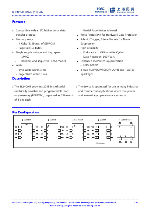
Features●Compatible with all I²C bidirectional datatransfer protocol●Memory array:– 4 Kbits (512bytes) of EEPROM–Page size: 16 bytes●Single supply voltage and high speed:–1MHZ–Random and sequential Read modes ●Write:–Byte Write within 3 ms–Page Write within 3 ms–Partial Page Writes Allowed●Write Protect Pin for Hardware Data Protection ●Schmitt Trigger, Filtered Inputs for NoiseSuppression●High-reliability–Endurance: 1 Million Write Cycles–Data Retention: 100 Years●Enhanced ESD/Latch-up protection–HBM 6000V●8-lead PDIP/SOP/TSSOP/ UDFN and TSOT23-5packagesDescription●The BL24C04F provides 2048 bits of serial electrically erasable and programmable read-only memory (EEPROM), organized as 256 words of 8 bits each. ●The device is optimized for use in many industrial and commercial applications where low-power and low-voltage operation are essential.Pin ConfigurationNC A1 A2 GNDVCCWPNCA1A2GNDNCA1A2GNDNCA1A2GNDVCCWPVCCWPVCCWP123487651234123487658765123487658-lead PDIP8-lead SOP8-lead TSSOP8-pad DFNBottem viewSCLSDASCLSDASCLSDASCLSDAWP VCCSCL SDAGND541235-lead TSOT23-5Pin DescriptionsTable 1Block DiagramFigure 1DEVICE/PAGE ADDRESSES (A2, A1 and A0): The A2, A1 and A0 pins are device address inputs that are hard wire for the BL24C04F. Eight 2K devices may be addressed on a single bus system (device addressing is discussed in detail under the Device Addressing section).SERIAL DATA (SDA): The SDA pin is bi-directional for serial data transfer. This pin is open-drain driven and may be wire-ORed with any number of other open-drain or open- collector devices.SERIAL CLOCK (SCL): The SCL input is used to positive edge clock data into each EEPROM device and negative edge clock data out of each device.WRITE PROTECT (WP):The BL24C04F has a Write Protect pin that provides hardware data protection. The Write Protect pin allows normal read/write operations when connected to ground (GND). When the Write Protection pin is connected to Vcc, the write protection feature is enabled and operates as shown in the following Table 2.Table 2Functional Description1.Memory OrganizationBL24C04F, 4K SERIAL EEPROM: Internally organized with 32 pages of 16 bytes each, the 4K requires a 9-bit data word address for random word addressing.2.Device OperationCLOCK and DATA TRANSITIONS: The SDA pin is normally pulled high with an external device. Data on the SDA pin may change only during SCL low time periods (see Figure 2). Data changes during SCL high periods will indicate a start or stop condition as defined below.START CONDITION: A high-to-low transition of SDA with SCL high is a start condition which must precede any other command (see Figure 3).STOP CONDITION: A low-to-high transition of SDA with SCL high is a stop condition. After a read sequence, the stop command will place the EEPROM in a standby power mode (see Figure 3).ACKNOWLEDGE: All addresses and data words are serially transmitted to and from the EEPROM in 8-bit words. The EEPROM sends a "0" to acknowledge that it has received each word. This happens during the ninth clock cycle.STANDBY MODE: The BL24C04F features a low-power standby mode which is enabled: (a) upon power-up and (b) after the receipt of the STOP bit and the completion of any internal operations.MEMORY RESET: After an interruption in protocol, power loss or system reset, any two-wire part can be reset by following these steps:1. Clock up to 9 cycles.2. Look for SDA high in each cycle while SCL is high.3. Create a start condition.BL24C04F 4Kbits (512×8)BL24C04F 4Kbits (512×8) Belling Proprietary Information. Unauthorized Photocopy and Duplication Prohibited4-20DATA STABLEDATA STABLEDATA CHANGESDASCLFigure 2. Data ValidityFigure 4. Output Acknowledge3.Device AddressingThe 4K EEPROM devices all require an 8-bit device address word following a start condition to enable the chip for a read or write operation (see Figure 5)MSB LSBFigure 5. Device AddressThe device address word consists of a mandatory "1", "0" sequence for the first four most significant bits as shown. This is common to all the Serial EEPROM devices.The 4K EEPROM uses A2 and A1 device address bits to allow as much as for devices on the same bus. These 2 bits must be compared to their corresponding hardwired input pins. The A2 and A1 pins use an internal proprietary circuit that biases them to a logic low condition if the pins are allowed to float.The eighth bit of the device address is the read/write operation select bit. A read operation is initiated if this bit is high and a write operation is initiated if this bit is low.Upon a compare of the device address, the EEPROM will output a "0". If a compare is not made, the chip will return to a standby state.DATA SECURITY: The BL24C04F has a hardware data protection scheme that allows the user to write protect the entire memory when the WP pin is at VCC.4.Write OperationsBYTE WRITE: A write operation requires an 9-bit data word address following the device address word and acknowledgment. Upon receipt of this address, the EEPROM will again respond with a "0" and then clock in the first 8-bit data word. Following receipt of the 8-bit data word, the EEPROM will output a "0" and the addressing device, such as a microcontroller, must terminate the write sequence with a stop condition. At this time the EEPROM enters an internally timed write cycle, tWR, to the nonvolatile memory. All inputs are disabled during this write cycle and the EEPROM will not respond until the write is complete (see Figure 7).MSB LSBFigure 6. ADDRESSSDA LINE STARTDEVICEADDRESSWRITEMSBLSBR/WACKADDRESSACKLSBACKLSBSTOPDATAFigure 7. Byte WritePAGE WRITE: The 4K EEPROM is capable of an 16-byte page write. A page write is initiated the same as a byte write, but the microcontroller does not send a stop condition after the first data word is clocked in. Instead, after the EEPROM acknowledges receipt of the first data word, the microcontroller can transmit up to seven more data words. The EEPROM will respond with a "0" after each data word received. The microcontroller must terminate the page write sequence with a stop condition (see Figure 8).ST A R TDEVICEADDRESSWRITEMSBLSBR/WACKADDRESSACKLSBACKLSBACKSTOPDATA(n)ACKDATA(n+1)DATA(n+1)SDALINEFigure 8. Page WriteThe data word address lower three bits are internally incremented following the receipt of each data word. The higher data word address bits are not incremented, retaining the memory page row location. When the word address, internally generated, reaches the page boundary, the following byte is placed at the beginning of the same page. If more than eight data words are transmitted to the EEPROM, the data word address will "roll over" and previous data will be overwritten.ACKNOWLEDGE POLLING: Once the internally timed write cycle has started and the EEPROM inputs are disabled, acknowledge polling can be initiated. This involves sending a start condition followed by the device address word. The read/write bit is representative of the operation desired. Only if the internal write cycle has completed will the EEPROM respond with a "0", allowing the read or write sequence to continue.5.Read OperationsRead operations are initiated the same way as write operations with the exception that the read/write select bit in the device address word is set to "1". There are three read operations: current address read, random address read and sequential read.CURRENT ADDRESS READ:The internal data word address counter maintains the last address accessed during the last read or write operation, incremented by one. This address stays valid between operations as long as the chip power is maintained. The address "roll over" during read is from the last byte of the last memory page to the first byte of the first page. The address "roll over" during write is from the last byte of the current page to the first byte of the same page. Once the device address with the read/write select bit set to "1" is clocked in and acknowledged by the EEPROM, the current address data word is serially clocked out. The microcontroller does not respond with an input "0" but does generate a following stop condition (see Figure 9).ST A R TDEVICEADDRESSREADMSBLSBR/WACKSTOPDATANOACKSDALINEFigure 9. Current Address ReadRANDOM READ: A random read requires a "dummy" byte write sequence to load in the data word address. Once the device address word and data word address are clocked in and acknowledged by the EEPROM, the microcontroller must generate another start condition. The microcontroller now initiates a current address read by sending a device address with the read/write select bit high. The EEPROM acknowledges the device address and serially clocks out the data word. The microcontroller does not respond with a "0" but does generate a following stop condition (see Figure 10)STA R TDEVICEADDRESSWRITEMSBLSBR/WACKNote.1*=DON'T CARE bitsADDRESSACKLSBSTOPDATA(n)DEVICEADDRESSSTARTREADACKNOACK DUMMY WRITESDALINEFigure 10. Random ReadSEQUENTIAL READ: Sequential reads are initiated by either a current address read or a random address read. After the microcontroller receives a data word, it responds with an acknowledge. As long as theEEPROM receives an acknowledge, it will continue to increment the data word address and serially clock out sequential data words. When the memory address limit is reached, the data word address will "roll over" and the sequential read will continue. The sequential read operation is terminated when the microcontroller does not respond with a "0" but does generate a following stop condition (see Figure 11).DEVICE ADDRESS READR/WACKACKACKACKSTOP DATA(n)DATA(n+1)DATA(n+2)DATA(n+x)NOACKSDALINEFigure 11. Sequential ReadElectrical CharacteristicsAbsolute Maximum Stress Ratings:●DC Supply Voltage . . . . . . . . . . . . . . . . . . . . . . . -0.3V to +6.5V●Input / Output Voltage . . . . . . . . . . . . . GND-0.3V to VCC+0.3V●Operating Ambient Temperature . . . . . . . . . . . . -40℃ to +85℃●Storage Temperature . . . . . . . . . . . . . . . . . . . . .-65℃ to +150℃●Electrostatic pulse (Human Body model) . . . . . . . . . . . . . 6000VComments:Stresses above those listed under "Absolute Maximum Ratings" may cause permanent damage to this device. These are stress ratings only. Functional operation of this device at these or any other conditions above those indicated in the operational sections of this specification is not implied or intended. Exposure to the absolute maximum rating conditions for extended periods may affect device reliability.DC Electrical CharacteristicsApplicable over recommended operating range from: TA = -40℃ to +85℃, VCC = +1.7V to +5.5V (unless otherwise noted)Pin CapacitanceApplicable over recommended operating range from TA = 25℃, f = 1.0 MHz, VCC = +1.7VAC Electrical CharacteristicsApplicable over recommended operating range from TA = -40℃ to +85℃, VCC = +1.8V to +5.5V, CL = 1 TTL Gate and 100 pF (unless otherwise noted)Bus TimingFigure 12. SCL: Serial Clock, SDA: Serial Data I/O Write Cycle TimingFigure 13. SCL: Serial Clock, SDA: Serial Data I/OPackage InformationPDIP Outline Dimensions1.This drawing is for general information only; refer to JEDEC Drawing MS-001, Variation BA for additional information.2. Dimensions A and L are measured with the package seated in JEDEC seating plane Gauge GS-3.3. D, D1 and E1 dimensions do not include mold Flash or protrusions. Mold Flash or protrusions shall not exceed 0.010 inch.4. E and eA measured with the leads constrained to be perpendicular to datum.5. Pointed or rounded lead tips are preferred to ease insertion.6. b2 and b3 maximum dimensions do not include Dambar protrusions. Dambar protrusions shall not exceed 0.010 (0.25 mm).Notes:These drawings are for general information only. Refer to JEDEC Drawing MS-012, Variation AA for proper dimensions, tolerances, datums, etc.1. This drawing is for general information only. Refer to JEDEC Drawing MO-153, Variation AA, for proper dimensions, tolerances, datums, etc.2. Dimension D does not include mold Flash, protrusions or gate burrs. Mold Flash, protrusions and gate burrs shall not exceed 0.15 mm (0.006 in) per side.3. Dimension E1 does not include inter-lead Flash or protrusions. Inter-lead Flash and protrusions shall not exceed 0.25 mm (0.010 in) per side.4. Dimension b does not include Dambar protrusion. Allowable Dambar protrusion shall be 0.08 mm total in excess of the b dimension at maximum material condition. Dambar cannot be located on the lower radius of the foot. Minimum space between protrusion and adjacent lead is 0.07 mm.5. Dimension D and E1 to be determined at Datum Plane H.Figure 17TSOT23-5Figure 18Marking DiagramPDIPBL24C04FYYWW#ZZSSSSSPYY: yearWW :weekZZ: assembly houseSSSSS : Lot IDSOPBL24C04FSSSSSP SSSSS : Lot IDTSSOPBL24C04FSSSSS SSSSS : Lot IDTSOT23-524C04FSSSSSP SSSSS : Lot IDOrdering InformationRevision history。
最全阿里巴巴国际站电子烟违禁词汇总

Wor品ui牌词 ETnoeprgy CThoapnsckeys
Basecom
Bilstar To-Strong
Blue-Chip
Boge
TransPower
City Hao Er Kang Bojingtong Uneast
Cokoo
Buddy
Unicig
Cycer
Brilliant Ovale
CYL Tech
Cijoy
vision
Dekang
Elego
Youshun
品牌词 Biansi kanger kangertech CIGGO Fantasia Atmos RX Zippo Incipio CM CASE-MATE
品牌词 e-hose e-hose mini ecigator Efest Smart vapeonly evo alips silverback ecigator
e-smart dual coil tank(DCT)
赛尔美smiss
聚创思Seego ghit ehit e-hit
dfgd
vision vision Spinner vision vt vision stv vViissioinonEtesrlniipty (RBA)
新宜康 卓尔悦
itaste
e liquids
alo pcc
Anodized SID liquids
cool fire
flavors
I taste
nicotine
hash oil ml
西格雷sigelei 赛乐宝slb 捷士宝jsb 博格boge
易佳特Aspire 九摩jomo nautilus bdc clearomizer eigate
AVVIO RAPIDO Router mobili 5G 安装指南说明书
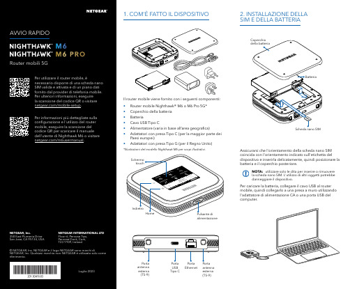
Per caricare la batteria, collegare il cavo USB al router mobile, quindi collegarlo a una presa a muro utilizzando l'adattatore di alimentazione CA o una porta USB del computer.Assicurarsi che l'orientamento della scheda nano SIM coincida con l'orientamento indicato sull'etichetta del dispositivo e inserirla delicatamente, quindi posizionare la batteria e il coperchio posteriore.NOTA: utilizzare solo le dita per inserire o rimuovere la scheda nano SIM. L'utilizzo di altri oggetti potrebbe danneggiare il dispositivo.1. COM'È FATTO IL DISPOSITIVO2. INSTALLAZIONE DELLA SIM E DELLA BATTERIAIl router mobile viene fornito con i seguenti componenti:• Router mobile Nighthawk® M6 o M6 Pro 5G*• Coperchio della batteria • Batteria• Cavo USB Tipo C• Alimentatore (varia in base all’area geografica)• Adattatori con presa Tipo C (per la maggior parte dei Paesi europei)•Adattatori con presa Tipo G (per il Regno Unito)*Illustrazioni del modello Nighthawk M6 per scopi illustrativi.antenna esterna (TS-9)antenna esterna (TS-9)USB Tipo CEthernetCONFORMITÀ NORMATIVA E NOTE LEGALIPer informazioni sulla conformità alle normative, compresala Dichiarazione di conformità UE, visitare il sito Web https:///it/about/regulatory/.Prima di collegare l'alimentazione, consultare il documento relativo alla conformità normativa.Può essere applicato solo ai dispositivi da 6 GHz: utilizzare il dispositivo solo in un ambiente al chiuso. L'utilizzo di dispositivi a 6 GHz è vietato su piattaforme petrolifere, automobili, treni, barche e aerei, tuttavia il suo utilizzo è consentito su aerei di grandi dimensioni quando volano sopra i 3000 metri di altezza. L'utilizzo di trasmettitori nella banda 5.925‑7.125 GHz è vietato per il controllo o le comunicazioni con sistemi aerei senza equipaggio.SUPPORTO E COMMUNITYDalla pagina del portale di amministrazione Web, fare clic sull'icona con i tre puntini nell'angolo in alto a destra per accedere ai file della guida e del supporto.Per ulteriori informazioni, visitare il sito netgear.it/support per accedere al manuale dell'utente completo e per scaricare gli aggiornamenti del firmware.È possibile trovare utili consigli anche nella Community NETGEAR, alla pagina /it.GESTIONE DELLE IMPOSTAZIONI TRAMITE L'APP NETGEAR MOBILEUtilizzare l'app NETGEAR Mobile per modificare il nome della rete Wi-Fi e la password. È possibile utilizzarla anche per riprodurre e condividere contenutimultimediali e accedere alle funzioni avanzate del router mobile.1. Accertarsi che il dispositivo mobile sia connesso a Internet.2. Eseguire la scansione del codice QR per scaricare l'appNETGEAR Mobile.Connessione con il nome e la password della rete Wi-Fi 1. Aprire il programma di gestione della rete Wi‑Fi deldispositivo.2. Individuare il nome della rete Wi‑Fi del router mobile(NTGR_XXXX) e stabilire una connessione.3. Only Connessione tramite EthernetPer prolungare la durata della batteria, l'opzione Ethernet è disattivata per impostazione predefinita. Per attivarla, toccare Power Manager (Risparmio energia) e passare a Performance Mode (Modalità performance).4. CONNESSIONE A INTERNETÈ possibile connettersi a Internet utilizzando il codice QR del router mobile da uno smartphone oppure selezionando manualmente il nome della rete Wi‑Fi del router e immettendo la password.Connessione tramite codice QR da uno smartphone 1. Toccare l'icona del codice QR sulla schermata inizialedello schermo LCD del router mobile.NOTA: quando è inattivo, lo schermo touch si oscura per risparmiare energia. Premere brevemente e rilasciare il pulsante di alimentazione per riattivare lo schermo.3. CONFIGURAZIONE DEL ROUTER MOBILETenere premuto il pulsante di accensione per due secondi, quindi seguire le istruzioni visualizzate sullo schermo per impostare un nome per la rete Wi‑Fi e una password univoci.La personalizzazione delle impostazioni Wi‑Fi consente di proteggere la rete Wi‑Fi del router mobile.Impostazioni APNIl router mobile legge i dati dalla scheda SIM e determina automaticamente le impostazioni APN (Access Point Name) corrette con i piani dati della maggior parte degli operatori. Tuttavia, se si utilizza un router mobile sbloccato con un operatore o un piano meno comune, potrebbe essere necessario immettere manualmente le impostazioni APN.Se viene visualizzata la schermata APN Setup Required (Configurazione APN richiesta), i dati APN dell’operatore non sono presenti nel nostro database ed è necessario inserirli manualmente. Immettere i valori fornitidall’operatore nei campi corrispondenti, quindi toccare Save (Salva) per completare la configurazione.NOTA: l’operatore determina le proprie informazioni APN e deve fornire le informazioni per il proprio piano dati. Si consiglia di contattare il proprio operatore per le impostazioni APN corrette e di utilizzare solo l’APN suggerito per il piano specifico.Schermata inizialeAl termine della configurazione, il router visualizza la schermata iniziale:Wi‑FiPotenza Carica Rete Codice QR connessione rapida Wi‑FiNome e Wi‑FiIcona del codice QR。
Color of the Year 2024: Peach Fuzz

Color of the Year 2024: Peach Fuzz佚名【期刊名称】《China Textile》【年(卷),期】2024()1【摘要】Pantone has declared Pantone 13-1023 Peach Fuzz as its Color of the Year for 2024.This soft peach tone reflects comforting warmth and represents a desire for unity,peace and personal well-being.The calming shade,a sublime blend of pink and orange,suggests freshsoftness,signifying an environment that invites relaxation,recovery and growth.The delicate hue of Pantone 13-1023 Peach Fuzz not only awakens our senses to the tactile and enveloping warmth of the color,but also influences our sense of peace and overall well-being.【总页数】2页(P50-51)【正文语种】中文【中图分类】R31【相关文献】1.基于Peach Fuzz的媒体网关安全测试2.Antioxidant Activity Assessment and Color Analysis of Skin from Different Peach Varieties Grown in South Carolina3.Color Forward^(TM)预测:和谐的色彩结合丰富的飞溅效果将成为2024年主流4.The prevalence of red-green color vision deficiency and its related factors in an elderly population above 60 years of age5.柔和桃Peach Fuzz因版权原因,仅展示原文概要,查看原文内容请购买。
美国bobo缩阴神器

美国bobo缩阴神器•科普一下美国bobo缩阴神器:1、产品简介美国索露雅商贸有限公司采用高端科技,为了保证作用成分的活性,采用零距离“超临界萃取“技术。
美国BO 没有毒副作用。
2、适用人群1、性生活频繁的女性:阴道干涩、阴道敏感程度低、润滑不足、性交疼痛、性2、经历过生育的女性:分娩之后,阴道松弛、没有弹性,性生活时对阴茎的紧握能力不足的女性。
3、希望提高夫妻生活质量的女性:性冷淡、性生活次数低于正常值,伴侣得不到正常满足的女性。
产品功美国BOBO不是药,而是提高女性生活品质的一种内生殖器官的保养护理产品,可以全面修复女性生殖系统。
1、美国BOBO具有细胞再生功能,修复破损黏膜,自然恢复生殖细胞的排异、抗菌、分泌、排泄等生理功能。
2、美国BOBO对于子宫黏膜、宫颈粘膜、阴道粘膜、阴唇及外阴皮肤具有全程的修复养护作用。
3促进女性荷尔蒙分泌,恢复女性特征,增强抗病能力。
4、美国BOBO属于纯生物制剂,和人体具有很好的共物共融性,尤其适用于多方用药、久治不愈的妇科慢性验证5、在夫妻生活中,使用美国BOBO可获得药物调理和生活和谐的双重效果。
产品成分美国BOBO含积雪草、珍稀蛇床子、玫瑰、苦参、冰片、雪莲、芦荟、灵芝等成分,弥补女性血气,提高阴道抵项1、阴道内置使用,请勿口服2、处女者禁用3、女性在月经期、妊娠期、哺乳期不宜使用4、月经期禁止使用,例假结束4天后方可使用5、使用期间不能同房,如需同房,请取出BOBO并清洗阴道方可同房6、如在中途取出不可重复使用7、取出后应及时清洗阴道,间隔72小时后,再用一粒。
8、同房3小时后方可使用使用方法1、将双手洗净,然后撕开铝封塑袋,检查本品是否包好,绑好2、将有消毒棉线的一端解开,并把消毒棉线的位置拉直3、将食指套上指套,然后放在有棉线的一端。
以食指配合大拇指把药丸捏紧,准备放置。
4、放置时,应尽量放松,一只手轻柔的将阴道分开,然后慢慢呼气,用套着指套的食指将药丸顺阴道轻缓推入5、当放置正确后应感觉不到药丸的存在,此时消毒棉线末端应留在阴道口外。
- 1、下载文档前请自行甄别文档内容的完整性,平台不提供额外的编辑、内容补充、找答案等附加服务。
- 2、"仅部分预览"的文档,不可在线预览部分如存在完整性等问题,可反馈申请退款(可完整预览的文档不适用该条件!)。
- 3、如文档侵犯您的权益,请联系客服反馈,我们会尽快为您处理(人工客服工作时间:9:00-18:30)。
NYSE
Hybrid market
Specialists Commission broker Independent floor brokers Registered traders
11
Copyright © 2010 Pearson Education, Inc. Publishing as Prentice Hall
Regulation NMS will fundamentally change US
stock trading
18
Copyright © 2010 Pearson Education, Inc. Publishing as Prentice Hall
Algorithmic Trading
Electronic trading systems that supplement or
Instinet
15
Copyright © 2010 Pearson Education, Inc. Publishing as Prentice Hall
Off-Exchange / Alternative Markets (cont.)
Alternative trading systems
16 Copyright © 2010 Pearson Education, Inc. Publishing as Prentice Hall
Evolving Stock Market Practices
Smart order routers
Internalization Alternative display facility Trade reporting facility Direct market access
Changes to US Stock Markets
Market structures of exchanges
Trading mechanisms of exchanges Consolidation among different types of assets Growth and diversity of off-exchange markets Consolidation internatrson Education, Inc. Publishing as Prentice Hall
Off-Exchange / Alternative Markets
Electronic communications networks
Privately owned off-exchange networks Archipelago
Quote Driven Dealer Markets
4
Copyright © 2010 Pearson Education, Inc. Publishing as Prentice Hall
Features of Markets
Order driven markets
Continuous market Call auction
Nasdaq
Competitive dealer, quote based system
Nasdaq National Market Small Cap Market SuperMontage
12
Copyright © 2010 Pearson Education, Inc. Publishing as Prentice Hall
replace human traders Benefits
Smaller transactions can avoid leaving footprint
Hide trading intentions Anonymity
19
Copyright © 2010 Pearson Education, Inc. Publishing as Prentice Hall
8
Copyright © 2010 Pearson Education, Inc. Publishing as Prentice Hall
Big Picture
9
Copyright © 2010 Pearson Education, Inc. Publishing as Prentice Hall
Exchanges
National exchanges
New York Stock Exchange American Stock Exchange
Regional exchanges
Chicago Philadelphia Boston Pacific
10 Copyright © 2010 Pearson Education, Inc. Publishing as Prentice Hall
Quote driven markets
Intermediaries, e.g., specialists of NYSE
Hybrid markets
NYSE Nasdaq
5 Copyright © 2010 Pearson Education, Inc. Publishing as Prentice Hall
All rights reserved. No part of this publication may be reproduced, stored in a retrieval system, or transmitted, in any form or by any means, electronic, mechanical, photocopying, recording, or otherwise, without the prior written permission of the publisher. Printed in the United States of America.
17
Copyright © 2010 Pearson Education, Inc. Publishing as Prentice Hall
SEC Regulation
Regulation NMS Order Protection Rule Trade-Through Rule Access Rule
Chapter 18
Markets for Common Stock: Structure and Organization
Exchanges
Exchange is market where intermediaries meet
to execute trades Two models of stock trading
Crossing networks Benefits: anonymity, reduced costs Cons: low execution rates, diminished quality of pricing LiquidNet, Pipeline, ITG Posit, BIDS Dark pools Benefits: non-displayed liquidity, anonymous trading, volume discovery, reduced market impact Cons: less or no visibility, difficulty to interact with order flow, no price discovery
20
Copyright © 2010 Pearson Education, Inc. Publishing as Prentice Hall
Options Market
Options trading
Options on individual stocks Options on indexes
Option exchanges
Options exchanges, e.g., CBOE and ISE Stock exchanges, e.g., Amex and Philadelphia
OTC Markets
OTC Bulletin Board
“Pink Sheet” Three parts to OTC market
Two under Nasdaq Unlisted stocks under OTC Bulletin and Pink
Sheets
13
Copyright © 2010 Pearson Education, Inc. Publishing as Prentice Hall
Features of Markets
Order driven markets
Continuous market Call auction
Quote driven markets
Intermediaries, e.g., specialists of NYSE
Hybrid markets
Order driven
Quote drive
Hybrid markets
2
Copyright © 2010 Pearson Education, Inc. Publishing as Prentice Hall
Structure of Stock Markets
3
Copyright © 2010 Pearson Education, Inc. Publishing as Prentice Hall
NYSE Nasdaq
6 Copyright © 2010 Pearson Education, Inc. Publishing as Prentice Hall