SIP12401DMP-T1-E3;中文规格书,Datasheet资料
1240P中文资料

Document Number: 63053For any questions, contact: foil@1240Vishay Foil ResistorsBulk Metal ® Foil Technology Precision TrimmingPotentiometers, 1/4 Inch Square, RJ26 Style, Designed to Meet or Exceed the Requirements of MIL-PRF-39035, Char. HFEATURES•Temperature coefficient of resistance (TCR): ± 10 ppm/°C. (- 55 °C to + 150 °C ref. at + 25 °C);through the wiper 3); ± 25 ppm/°C (see table 2 for low values)•Load life stability: 0.1 % typical ΔR, 1.0 % maximum ΔR under full rated power at + 85 °C for 10000 h •Settability: 0.05 % typical; 0.1 % maximum•Setting stability: 0.1 % typical; 0.5 % maximum, ΔSS •Power rating: 0.25 W at + 85 °C •Resistance range: 5 Ω to 10 k ΩNote:* See Figure 1, next pageTABLE 1 - MODEL SELECTION *MODELTERMINATION STYLE AVERAGE WEIGHT (g)POWER RATING at + 85 °C AMBIENTNO. OF TURNS1240W-edge mount, top adjust0.40.25 W21 ± 2X-edge mount, side adjust P-horizontal mount, side adjustTABLE 2 -1240 (RJ26) SERIESELECTRICAL SPECIFICATIONSTemperature Coefficient of Resistance (TCR) 50 Ω to 10K End-to-end 2)± 10 ppm/°C maximum (- 55 °C to + 150 °C,+ 25 °C ref.)Temperature Coefficient of Resistance 5, 10 and 20 ΩThrough the wiper 3)± 20 ppm/°C ± 25 ppm/°CStabilityLoad life at 10000 h0.1 % typical ΔR 1.0 % maximum ΔR(under full rated power of 0.25 W at + 85 °C)Power Rating 4)0.25 W at + 85 °C Settability 0.05 % typical;0.1 % maximum Setting Stability 0.1 % typical;0.5 % maximum Contact Resistance Variation - CRV (noise)5) 3 Ω typical; 10 Ω maximum Hop-off0.25 % typical;1.0 % maximum High-Frequency Operation Rise time Inductance Capacitance1.0 ns without ringing 0.08 µH typical 0.5 pF typical Operating Temperature Range- 55 °C to + 150 °CTABLE 3 - VALUES VS. TOLERANCESSTANDARD RESISTANCE VALUES(in Ω)STANDARD TOLERANCE5, 10± 10 %20, 50, 100, 200, 500, 1K, 2K, 5K, 10K± 5 %TABLE 4 - MECHANICAL SPECIFICATIONSAdjustment Turns 21 ± 2Mechanical Stops Wiper idles - no discontinuity InternalTerminations All welded - no fluxCase Material1240X - diallyl-phthalate: green (DAP)1240W - diallyl-phthalate: green (DAP)1240P - thermoplastic: blackShaft Torque 3 oz. in. maximum Backlash0.005 % typical1240Vishay Foil ResistorsBulk Metal ® Foil Technology Precision Trimming Potentiometers, 1/4 Inch Square, RJ26 Style, Designed to Meet or Exceed the Requirements of MIL-PRF-39035, Char. H For any questions, contact: foil@Document Number: 63053Document Number: 63053For any questions, contact: foil@1240Bulk Metal ® Foil Technology Precision Trimming Potentiometers, 1/4 Inch Square, RJ26 Style, Designed to Meet or Exceed the Requirements of MIL-PRF-39035, Char. HVishay Foil Resistors Notes:1.Maximum is 1.0 % A.Q.L. standard for all specifications except TCR. (For TCR information, see notes 2 and 3.)2.Maximum TCR applies to the 3 σ (sigma) limit or 99.73 % of a production lot. (Measured end-to-end with wiper off the element.)3.Measurements of TCR through the wiper are influenced more by setting stability and the percentage of the total resistance in use (at the wiper) than by fundamental resistance change due to temperature alone. The parameter shown in Table 2 is a 2 s distribution typifying the behavior of the device when used with 40% or more of the total resistance in use.4.Derated linearly for full power at + 85 °C to zero (0) W at +150°C.See Figure 2 on previous page.5.Independent of resistance value. 3 W maximum available on special request.6.All ΔR’s are measured to the tolerance specified + 0.01 Ω.7.Whichever is greater.Special Available Options:Special markingBurn-in and screening operations.VISHAY TRIMMERS ARE INSPECTED100 % for:•Short-time overload(6.25 x rated power for 5 s on; and for 30 s off - 3 cycles)•Immersion•Resistance tolerance check •End resistance •Visual-mechanical•Dynamic tests for continuity, CRV By sample for:•TCR •DWVTABLE 5 - COMPARISONMIL-PRF-39035/3 CHARACTERISTIC H 6)MODEL 1240 MAXIMUM TEST GROUP I ConditioningContact resistance variation - CRV (noise)Immersion± 1.0 %± 3.0 % or 3 Ω7)No continuous stream of bubbles± 0.5 %3 Ω typical, 10 Ω maximum No continuous stream of bubbles TEST GROUP I aVisual and mechanicalActual effective electrical travel End resistanceDielectric withstanding voltage - DWV (atmospheric and barometric pressure)Insulation resistance Shaft torque Thermal shock Setting stability No failures 10 to 25 turns 2 % or 2 Ω7)Per MIL-STD-202, methods 301 and 105≥ 1000 M Ω3 oz. in. maximum± 1.0 %± 1.0 %No failures 21 ± 2 turns2 Ω for values ≤ 1 k Ω;5 Ω for values ≥ 2 k Ω;Per MIL-STD-202, methods 301 and 105> 1000 M Ω3 oz. in. maximum± 0.5 %± 0.5 %TEST GROUP II SolderabilityPer MIL-STD-202, method 208Per MIL-STD-202, method 208TEST GROUP IIIResistance temperature characteristic - TCR Moisture resistanceContact resistance variation - CRV (noise)± 0.005 % (± 50 ppm/°C)± 1.0 %3.0 % or 3 Ω7)± 0.001 % (± 10 ppm/°C)± 0.5 %3 Ω typical, 10 Ω maximum TEST GROUP IV Settability ShockSetting stability VibrationSetting stabilityContact resistance variation - CRV (noise)Salt spray± 1.0 %± 1.0 %± 1.0 %± 1.0 %± 1.0 %3.0 % or 3 Ω7)No corrosion ± 0.1 %± 0.5 %± 0.5 %± 0.5 %± 0.5 %3 Ω typical, 10 Ω maximumNo corrosion TEST GROUP V Solder heatLow-temperature operation Setting stabilityLow-temperature storage High-temperature exposure Setting stabilityContact resistance variation - CRV (noise)Integrity of shaft± 1.0 %± 1.0 %± 2.0 %± 1.0 %± 3.0 %± 2.0 %3 % or 3 Ω7)No loosening or breakage± 0.1 %± 0.5 %± 0.5 %± 0.5 %± 0.5 %± 0.5 %3 Ω typical, 10 Ω maximum No loosening or breakage TEST GROUP VIRotational life (200 cycles)Contact resistance variation - CRV (noise)T erminal strength ± 2.0 %3 % or 3 Ω7)2 lbs.± 2.0 %3 Ω typical, 10 Ω maximum2 lbs.TEST GROUP VIILife (2000 h) at + 85 °C Life (10000 h) at + 85 °C ± 3.0 %± 5.0 %± 0.1 % typical, ± 1.0 % maximum ± 0.1 % typical, ± 1.0 % maximumTEST GROUP VIII Solvent resistance No failuresNo failures1240Vishay Foil ResistorsBulk Metal ® Foil Technology Precision Trimming Potentiometers, 1/4 Inch Square, RJ26 Style, Designed to Meet or Exceed the Requirements of MIL-PRF-39035, Char. H For any questions, contact: foil@Document Number: 63053Note* Application engineering release: for non-standard requests, please contact application engineering.TABLE 6 - GLOBAL PART NUMBER INFORMATIONNEW GLOBAL PART NUMBER:Y4053500R000J0L (preferred part number format)DENOTES PRECISIONVALUE AER*YR = ΩK = k Ω0 = standard part, gold termination 1 - 999 = customPRODUCT CODE TOLERANCE PACKAGING 4053 = 1240W 5053 = 1240X 0053 = 1240PJ = ± 5 %K = ± 10 %L = bulk packFOR EXAMPLE: ABOVE GLOBAL ORDER Y4053 500R000 J 0 L:TYPE: 1240W VALUE: 500.0 ΩABSOLUTE TOLERANCE: ± 5.0 %AER: standard part, gold termination PACKAGING: bulk packHISTORICAL PART NUMBER:1240W 500R00J B (will continue to be used)1240W 500R00J B MODEL RESISTANCE VALUE TOLERANCE PACKAGING 1240W 1240X 1240P500R00 = 500.0 ΩJ = ± 5 %K = ± 10 %B = bulk pack05350R 00Y 4J 00LDisclaimer Legal Disclaimer NoticeVishayAll product specifications and data are subject to change without notice.Vishay Intertechnology, Inc., its affiliates, agents, and employees, and all persons acting on its or their behalf (collectively, “Vishay”), disclaim any and all liability for any errors, inaccuracies or incompleteness contained herein or in any other disclosure relating to any product.Vishay disclaims any and all liability arising out of the use or application of any product described herein or of any information provided herein to the maximum extent permitted by law. The product specifications do not expand or otherwise modify Vishay’s terms and conditions of purchase, including but not limited to the warranty expressed therein, which apply to these products.No license, express or implied, by estoppel or otherwise, to any intellectual property rights is granted by this document or by any conduct of Vishay.The products shown herein are not designed for use in medical, life-saving, or life-sustaining applications unless otherwise expressly indicated. Customers using or selling Vishay products not expressly indicated for use in such applications do so entirely at their own risk and agree to fully indemnify Vishay for any damages arising or resulting from such use or sale. Please contact authorized Vishay personnel to obtain written terms and conditions regarding products designed for such applications.Product names and markings noted herein may be trademarks of their respective owners.元器件交易网Document Number: 。
UPC2771TB-E3资料
Document No. P12710EJ2V0DS00 (2nd edition) Date Published June 1999 N CP(K)Printed in Japan1997, 1999©The mark shows major revised points.Data Sheet P12710EJ2V0DS002PIN CONNECTIONSMarking is an example of µPC2762TBPRODUCT LINE-UP (T A = +25 °C, V CC = V out = 3.0 V, Z L = Z S = 50 Ω)Part No.f u (GHz)P O (1 dB)(dBm)P O (sat)(dBm)G P (dB)I CC (mA)PackageMarkingµPC2762T 2.9+8.0+9.01326.56-pin minimold µPC2762TB 6-pin super minimoldµPC2763T 2.7+9.5+11.02027.06-pin minimold µPC2763TB 6-pin super minimoldµPC2771T 2.2+11.5+12.52136.06-pin minimold µPC2771TB6-pin super minimoldRemark Typical performance. Please refer to ELECTRICAL CHARACTERISTICS in detail.Notice The package size distinguishes between minimold and super minimold.C2HPin No.Pin Name 1INPUT 2GND 3GND 4OUTPUT 5GND 6V CC456321(Top View)C 1Z321456(Bottom View)C1ZC2AData Sheet P12710EJ2V0DS003SYSTEM APPLICATION EXAMPLEDigital cellular telephoneIPC2763TB PC2771TBµµNote The insertion point is different due to the specifications of conjunct devices.For conjunction with your devices, refer to the data sheets to confirm their conbination.PIN EXPLANATIONNote Pin voltage is measured at V CC = 3.0 V. Above: µPC2762TB, Center: µPC2763TB, Below: µPC2771TB.4Data Sheet P12710EJ2V0DS00ABSOLUTE MAXIMUM RATINGSRatingsParameter Symbol ConditionsµPC2762TBµPC2763TB µPC2771TBUnitSupply Voltage V CC T A = +25 °C, pin 4 and 6 3.6VTotal Circuit Current I CC T A = +25 °C7077.7mAPower Dissipation P D Mounted on double copper clad50 × 50 × 1.6 mm epoxy glass PWBT A = +85 °C200mWOperating AmbientTemperatureT A−40 to +85°C Storage Temperature T stg−55 to +150°C Input Power P in T A = +25 °C+10+13dBm RECOMMENDED OPERATING CONDITIONSParameter Symbol MIN.TYP.MAX.Unit RemarkSupply Voltage V CC 2.7 3.0 3.3V Same voltage should be applied to pin4 and 6.Operating AmbientTemperatureT A−40+25+85°C−Operating Frequency f opt0.8− 1.9GHz Only for µPC2771TBData Sheet P12710EJ2V0DS005ELECTRICAL CHARACTERISTICS (T A = +25 °C, V CC = V out = 3.0 V, Z L = Z S = 50 Ω)µPC2762TB, µPC2763TBµPC2762TBµPC2763TB Parameter Symbol Test ConditionsMIN.TYP.MAX.MIN.TYP.MAX.Unit Circuit Current I CC No signal−26.535.0−27.035.0mAPower Gain G P f = 0.9 GHzf = 1.9 GHz1111.51315.51617.5181820212324dBNoise Figure NF f = 0.9 GHzf = 1.9 GHz −−6.57.08.09.0−−5.55.57.07.5dBUpper Limit Operating Frequency f u 3 dB down belowfrom gain atf = 0.1 GHz2.7 2.9− 2.3 2.7−GHzIsolation ISL f = 0.9 GHzf = 1.9 GHz 22202725−−25243029−−dBInput Return Loss RL in f = 0.9 GHzf = 1.9 GHz 6.05.59.08.5−−8.08.011.011.0−−dBOutput Return Loss RL out f = 0.9 GHzf = 1.9 GHz 8.09.011.012.0−−5.06.07.09.0−−dB1 dB Gain Compres-sion Output Level P O (1 dB) f = 0.9 GHzf = 1.9 GHz+5.5+4.5+8.0+7.0−−+7.0+4.0+9.5+6.5−−dBmµPC2771TBµPC2771TB Parameter Symbol Test ConditionsMIN.TYP.MAX.Unit Circuit Current I CC No signal−36.045.0mAPower Gain G P f = 0.9 GHzf = 1.5 GHz 191821212424dBNoise Figure NF f = 0.9 GHzf = 1.5 GHz −−6.06.07.57.5dBUpper Limit OperatingFrequencyf u 3 dB down below from gain at f = 0.1 GHz 1.8 2.2−GHzIsolation ISL f = 0.9 GHzf = 1.5 GHz 25253030−−dBInput Return Loss RL in f = 0.9 GHzf = 1.5 GHz 10101414−−dBOutput Return Loss RL out f = 0.9 GHzf = 1.5 GHz 6.55.59.08.5−−dB1 dB Gain Compres-Sion Output Level P O (1 dB) f = 0.9 GHzf = 1.5 GHz+9.0+7.0+11.5+9.5−−dBmSaturated Output Power Level P O (sat) f = 0.9 GHzf = 1.5 GHz−−+12.5+11−−dBmData Sheet P12710EJ2V0DS006STANDARD CHARACTERISTICS FOR REFERENCE (T A = +25 °C, V CC = V out = 3.0 V, Z L = Z S = 50 Ω)µPC2762TB, µPC2763TBReferenceµPC2762TBµPC2763TB Parameter Symbol Test ConditionsMIN.TYP.MAX.MIN.TYP.MAX.UnitSaturated Output Power Level P O (sat) f = 0.9 GHzf = 1.9 GHz−−+9.0+8.5−−−−+11.0+8.0−−dBmAdjacent channel power P adj f = 0.9 GHzπ/4 QPSK wave NoteP O = +4 dBm∆f = ±50 kHz∆f = ±100 kHz−−−64−64−−−−−61−62−−dBcThird order intermodulation IM3 2 sine wave input.Output of each tonef1 = 0.900 GHzf2 = 0.902 GHz−−16−−−27−dBcdistortion P O(each) = +4 dBm f1 = 1.900 GHzf2 = 1.902 GHz−−10−−−14−dBc µPC2771TBReferenceµPC2771TB Parameter Symbol Test ConditionsMIN.TYP.MAX.UnitAdjacent channel power 1P adj1 f = 0.9 GHzπ/4 QPSK wave NoteP O = +7 dBm∆f = ±50 kHz∆f = ±100 kHz−−−61−72−−dBcAdjacent channel power 2P adj2 f = 1.5 GHzπ/4 QPSK wave NoteP O = +7 dBm∆f = ±50 kHz∆f = ±100 kHz−−−59−71−−dBcThird order intermodulation IM3 2 sine wave input.Output of each tonef1 = 0.900 GHzf2 = 0.902 GHz−−18−dBcdistortion P O (each) = +7 dBm f1 = 1.500 GHzf2 = 1.502 GHz−−12−dBc Noteπ/4 DQPSK modulated wave input, data rate 42 kbps, Filter roll off α = 0.5, PN 9Data Sheet P12710EJ2V0DS007TEST CIRCUITINOUTCOMPONENTS OF TEST CIRCUIT EXAMPLE OF ACTUAL APPLICATION COMPONENTSFOR MEASURING ELECTRICALCHARACTERISTICSType Value Type Value Operating Frequency C1, C2Bias Tee 1 000 pF C1 to C3Chip capacitor 1 000 pF100 MHz or higher C3Capacitor 1 000 pF L Chip inductor100 nH100 MHz or higherL Bias Tee 1 000 nH10 nH 2.0 GHz or higherINDUCTOR FOR THE OUTPUT PINThe internal output transistor of this IC consumes 20 mA, to output medium power. To supply current for output transistor, connect an inductor between the Vcc pin (pin 6) and output pin (pin 4). Select large value inductance, as listed above.The inductor has both DC and AC effects. In terms of DC, the inductor biases the output transistor with minimum voltage drop to output enable high level. In terms of AC, the inductor make output-port-impedance higher to get enough gain. In this case, large inductance and Q is suitable.For above reason, select an inductance of 100 Ω or over impedance in the operating frequency. The gain is a peak in the operating frequency band, and suppressed at lower frequencies.The recommendable inductance can be chosen from example of actual application components list as shown above.CAPACITORS FOR THE V CC, INPUT, AND OUTPUT PINSCapacitors of 1 000 pF are recommendable as the bypass capacitor for the Vcc pin and the coupling capacitors for the input and output pins.The bypass capacitor connected to the Vcc pin is used to minimize ground impedance of Vcc pin. So, stable bias can be supplied against Vcc fluctuation.The coupling capacitors, connected to the input and output pins, are used to cut the DC and minimize RF serial impedance. Their capacitance are therefore selected as lower impedance against a 50 Ω load. The capacitors thus perform as high pass filters, suppressing low frequencies to DC.To obtain a flat gain from 100 MHz upwards, 1 000 pF capacitors are used in the test circuit. In the case of under 10 MHz operation, increase the value of coupling capacitor such as 10 000 pF. Because the coupling capacitors are determined by equation, C = 1/(2πRfc).8Data Sheet P12710EJ2V0DS00Data Sheet P12710EJ2V0DS009ILLUSTRATION OF THE TEST CIRCUIT ASSEMBLED ON EVALUATION BOARDC1Z321456→Top ViewMounting direction(Marking is an example for PC2762TB)Notes1.2.3.4.30 × 30 × 0.4 mm double sided copper clad polyimide board.Back side: GND pattern Solder plated on pattern : Through holesFor more information on the use of this IC, refer to the following application note: USAGE AND APPLICATION OF SILICON MEDIUM-POWER HIGH-FREQUENCY AMPLIFIER MMIC (P12152E).COMPONENT LISTValueC 1 000 pF LExample: 10 nHData Sheet P12710EJ2V0DS0010TYPICAL CHARACTERISTICS (Unless otherwise specified, T A = +25 °C)− µPC2762TB −CIRCUIT CURRENT vs. SUPPLY VOLTAGECIRCUIT CURRENT vs. OPERATING AMBIENT TEMPERATUREC i r c u i t C u r r e n t I C C (m A )Supply Voltage V CC (V)Operating Ambient Temperature T A (°C)Frequency f (GHz)ISOLATION vs. FREQUENCYINPUT RETURN LOSS, OUTPUT RETURN LOSS vs. FREQUENCY I s o l a t i o n I S L (d B )Frequency f (GHz)Frequency f (GHz)Frequency f (GHz)–601020304050–40–200+20+40+60+80+100No signal V CC = 3.0 V NOISE FIGURE AND INSERTION POWER GAIN vs. FREQUENCYINSERTION POWER GAIN vs. FREQUENCY C i r c u i t C u r r e n t I C C (m A )I n s e r t i o n P o w e r G a i n G P (d B )No signal 010203040501234–40–30–200–10 1.0 3.00.10.3VCC = 3.0 VI n p u t R e t u r n L o s s R L i n (d B )O u t p u t R e t u r n L o s s R L o u t (d B )–40–30–201.0 3.0–100.30.1N o i s e F i g u r e N F (d B )1.03.00.30.180.110121416181.0 3.00.3− µPC2762TB −OUTPUT POWER vs. INPUT POWEROUTPUT POWER vs. INPUT POWERO u t p u t P o w e r P o u t (d B m )O u t p u t P o w e r P o u t (d B m )Input Power P in (dBm)Input Power P in (dBm)S a t u r a t e d O u t p u t P o w e r P O (s a t ) (d B m )Frequency f (GHz)–10–5+15+5+10–10–20–50+5+10+15–15–10–50+5OUTPUT POWER vs. INPUT POWEROUTPUT POWER vs. INPUT POWER O u t p u t P o w e r P o u t (d B m )–10–20–15+5–5+15+5+10–10–50Frequency f (GHz)+30.1+9+11+13+5+71.0 3.00.30.3 1.0 3.00.1− µPC2762TB −THIRD ORDER INTERMODULATION DISTORTION vs. OUTPUT POWER OF EACH TONETHIRD ORDER INTERMODULATION DISTORTION vs. OUTPUT POWER OF EACH TONET h i r d O r d e r I n t e r m o d u l a t i o n D i s t o r t i o n I M 3 (d B c )Output Power of Each Tone P O (each) (dBm)Output Power of Each Tone P O (each) (dBm)0–15–10–20–30–50–60–10–50+5+10T h i r d O r d e r I n t e r m o d u l a t i o n D i s t o r t i o n I M 3 (d B c )–400–15–10–20–30–50–60–10–50+5+10–40S-PARAMETER (T A = +25 °C, V CC = V out = 3.0 V)−µPC2762TB −S11-FREQUENCYS22-FREQUENCYTYPICAL S-PARAMETER VALUES (T A = +25 °C)µPC2762TBV CC = V out = 3.0 V, I CC = 29 mAFREQUENCY S11S21S12S22K MHz MAG.ANG.MAG.ANG.MAG.ANG.MAG.ANG.100.00000.338−1.3 4.560−3.40.039 1.00.310−5.5 2.23 200.00000.346−2.0 4.581−7.60.039 2.70.311−9.5 2.20 300.00000.348−1.2 4.616−11.30.039 6.80.302−12.3 2.20 400.00000.340−1.9 4.661−15.80.0408.10.296−16.2 2.18 500.00000.329−3.1 4.689−19.50.04011.60.290−20.2 2.20 600.00000.324−6.2 4.726−23.60.04113.70.292−24.1 2.12 700.00000.341−8.1 4.844−27.40.04215.80.291−26.2 2.01 800.00000.359−7.6 4.927−31.50.04318.10.292−28.3 1.90 900.00000.378−6.5 5.057−35.80.04419.30.284−30.9 1.77 1000.00000.375−5.1 5.179−41.00.04520.30.280−35.3 1.72 1100.00000.363−5.2 5.306−45.90.04722.10.285−40.0 1.64 1200.00000.353−6.7 5.400−51.00.04723.70.288−43.4 1.62 1300.00000.357−8.8 5.567−56.50.04826.10.288−45.7 1.54 1400.00000.377−11.7 5.706−61.70.04924.50.285−47.9 1.44 1500.00000.402−12.7 5.820−68.00.05226.70.282−52.8 1.32 1600.00000.414−13.2 5.987−73.70.05226.80.285−58.1 1.27 1700.00000.426−13.6 6.081−80.10.05529.00.288−62.0 1.18 1800.00000.434−16.1 6.182−86.70.05628.20.291−66.1 1.14 1900.00000.448−19.0 6.229−93.20.05728.50.286−70.4 1.09 2000.00000.463−21.7 6.328−99.70.05728.00.282−76.2 1.07 2100.00000.483−23.9 6.382−106.70.05828.50.282−81.5 1.01 2200.00000.492−25.8 6.431−113.80.05829.00.282−86.90.99 2300.00000.492−29.7 6.424−121.20.06030.10.278−91.70.99 2400.00000.486−34.6 6.329−128.80.06030.20.268−98.4 1.01 2500.00000.489−40.4 6.146−136.10.06231.10.260−104.5 1.02 2600.00000.500−44.6 5.997−143.10.06132.10.251−111.3 1.05 2700.00000.511−48.5 5.822−149.90.06431.40.248−116.7 1.03 2800.00000.511−50.4 5.693−157.00.06634.00.237−121.5 1.04 2900.00000.494−52.9 5.553−163.00.06533.80.222−128.3 1.11 3000.00000.465−55.9 5.334−169.50.06535.50.203−134.5 1.20 3100.00000.441−60.6 5.157−175.50.06635.50.189−141.1 1.27TYPICAL CHARACTERISTICS (Unless otherwise specified, T A = +25 °C)− µPC2763TB −CIRCUIT CURRENT vs. SUPPLY VOLTAGE CIRCUIT CURRENT vs. OPERATING AMBIENT TEMPERATUREFrequency f (GHz)Frequency f (GHz)N o i s e F i g u r e N F (d B )50.10.10.3 1.070.3 1.0 3.064− µPC2763TB −OUTPUT POWER vs. INPUT POWEROUTPUT POWER vs. INPUT POWERO u t p u t P o w e r P o u t (d B m )O u t p u t P o w e r P o u t (d B m )Input Power P in (dBm)Input Power P in (dBm)Input Power P in (dBm)SATURATED OUTPUT POWER vs.FREQUENCYSATURATED OUTPUT POWER vs.FREQUENCYS a t u r a t e d O u t p u t P o w e r P O (s a t ) (d B m )Frequency f (GHz)Input Power P in (dBm)OUTPUT POWER vs. INPUT POWEROUTPUT POWER vs. INPUT POWER O u t p u t P o w e r P o u t (d B m )Frequency f (GHz)–5+30.10+5+10+15+9+11+13+15–10–25+5+10+15+5+10+15–20–15–10–50–5+5+71.0 3.00.11.0 3.0–25–20–15–10–50–25–20–15–10–50–25–20–15–10–500.30.3–100–5–10− µPC2763TB −T h i r d O r d e r I n t e r m o d u l a t i o n D i s t o r t i o n I M 3 (d B c )Output Power of Each Tone P O (each) (dBm)Output Power of Each Tone P O (each) (dBm)T h i r d O r d e r I n t e r m o d u l a t i o n D i s t o r t i o n I M 3 (d B c )THIRD ORDER INTERMODULATION DISTORTION vs.OUTPUT POWER OF EACH TONETHIRD ORDER INTERMODULATION DISTORTION vs.OUTPUT POWER OF EACH TONE0–15–10–20–50–60–10–50+5+100–20–30–50–60–10–30–40–40–15–10–50+5+10S-PARAMETER (T A = +25 °C, V CC = V out = 3.0 V)−µPC2763TB −S11-FREQUENCYS22-FREQUENCY3.0 G0.1 G2.0 G1.0 GTYPICAL S-PARAMETER VALUES (T A = +25 °C)µPC2763TBV CC = V out = 3.0 V, I CC = 28 mAFREQUENCY S11S21S12S22 K MHz MAG.ANG.MAG.ANG.MAG.ANG.MAG.ANG.100.00000.231−1.410.210−3.80.023 2.40.406−4.1 1.68 200.00000.242−0.210.305−8.50.0237.80.412−7.5 1.66 300.00000.250 2.710.464−12.90.0249.30.407−9.9 1.58 400.00000.245 2.810.655−18.20.02413.40.407−13.9 1.55 500.00000.242 2.010.863−22.80.02616.10.405−17.6 1.44 600.00000.241−2.211.093−28.10.02719.90.414−21.6 1.37 700.00000.263−5.311.544−33.20.02822.30.419−24.6 1.25 800.00000.291−5.611.843−39.00.02922.50.424−27.7 1.16 900.00000.316−5.112.291−45.10.02923.90.424−31.9 1.09 1000.00000.322−4.012.676−52.40.03025.60.425−37.1 1.02 1100.00000.318−5.413.066−59.80.03124.10.438−42.50.96 1200.00000.309−9.013.311−67.30.03127.00.442−47.80.96 1300.00000.322−14.213.661−75.80.03328.80.441−51.20.90 1400.00000.344−20.613.845−83.90.03328.50.434−56.00.87 1500.00000.371−23.713.824−93.00.03530.10.435−62.20.82 1600.00000.380−27.513.890−101.50.03528.10.439−68.90.80 1700.00000.388−30.613.634−110.50.03629.20.439−74.60.78 1800.00000.378−36.413.236−119.60.03529.90.428−81.30.84 1900.00000.378−42.112.724−127.90.03530.90.411−87.00.89 2000.00000.375−46.612.290−136.10.03532.90.393−93.40.94 2100.00000.369−50.511.707−144.00.03533.00.385−99.60.99 2200.00000.351−53.811.130−151.70.03635.70.373−104.9 1.06 2300.00000.331−59.810.524−159.10.03636.80.359−110.3 1.13 2400.00000.306−66.49.824−165.90.03438.70.336−117.5 1.31 2500.00000.300−73.19.152−172.30.03540.10.321−123.3 1.41 2600.00000.294−75.88.583−178.20.03443.80.306−129.4 1.55 2700.00000.290−77.18.029176.20.03546.30.299−133.9 1.58 2800.00000.270−77.77.610170.60.03747.70.288−138.6 1.63 2900.00000.248−78.77.240166.10.03951.10.270−143.6 1.67 3000.00000.219−82.3 6.827161.20.03953.60.253−150.1 1.79 3100.00000.198−88.7 6.516156.90.04055.10.244−156.2 1.88TYPICAL CHARACTERISTICS (Unless otherwise specified, T A = +25 °C)− µPC2771TB −CIRCUIT CURRENT vs. OPERATING AMBIENT TEMPERATUREC i r c u i t C u r r e n t I C C (m A )I s o l a t i o n I S L (d B )Frequency f (GHz)Frequency f (GHz)CIRCUIT CURRENT vs. SUPPLY VOLTAGE2422201816I n s e r t i o n P o w e r G a i n G P (d B )502000.10.10.3 1.0 3.01.0 3.0103040140.312108656743N o i s e F i g u r e N F (d B )–10–20–30–40Data Sheet P12710EJ2V0DS0021− µPC2771TB −OUTPUT POWER vs. INPUT POWER O u t p u t P o w e r P o u t (d B m )O u t p u t P o w e r P o u t (d B m )O u t p u t P o w e r P o u t (d B m )Input Power P in (dBm)Input Power P in (dBm)OUTPUT POWER vs. INPUT POWER–5–10+15+15–5+5+10+15+5+10+10+5–5–10–20–15–100–25–5–20–15–10–25–5Data Sheet P12710EJ2V0DS0022− µPC2771TB −S a t u r a t e d O u t p u t P o w e r P O (s a t ) (d B m )T h i r d O r d e r I n t e r m o d u l a t i o n D i s t o r t i o n I M 3 (d B c )Output Power of Each Tone P O (each) (dBm)Output Power of Each Tone P O (each) (dBm)SATURATED OUTPUT POWER vs.FREQUENCYSATURATED OUTPUT POWER vs.FREQUENCY+17+9–60–30–5+10+7+13+15–50–40–20–10+11+500–10–15+10–50–10+5–15+5S-PARAMETER (T A = +25 °C, V CC = V out = 3.0 V)−µPC2771TB −S11-FREQUENCYS22-FREQUENCYData Sheet P12710EJ2V0DS0023TYPICAL S-PARAMETER VALUES (T A = +25 °C)µPC2771TBV CC = V out = 3.0 V, I CC = 35 mAFREQUENCY S11S21S12S22 K MHz MAG.ANG.MAG.ANG.MAG.ANG.MAG.ANG.100.00000.04519.710.570−4.70.0280.80.327−6.2 1.65 200.00000.05737.010.638−9.50.028 5.00.325−11.5 1.63 300.00000.07541.310.775−14.10.0298.60.323−16.2 1.58 400.00000.09043.311.004−19.40.03011.10.326−20.9 1.49 500.00000.10542.211.275−24.40.03014.90.331−26.4 1.45 600.00000.11840.211.586−30.00.03115.80.342−32.0 1.37 700.00000.13834.912.041−35.90.03119.80.350−37.3 1.29 800.00000.16332.512.367−42.10.03220.10.359−42.8 1.20 900.00000.18629.412.844−48.80.03223.20.361−49.4 1.15 1000.00000.20226.313.300−56.60.03223.90.371−56.1 1.11 1100.00000.21921.713.771−64.60.03324.90.389−62.5 1.03 1200.00000.23315.414.082−73.50.03326.60.400−69.30.99 1300.00000.2528.414.365−83.20.03628.80.405−75.40.92 1400.00000.267−0.114.336−92.60.03630.00.402−83.60.91 1500.00000.285−6.814.142−102.40.03632.00.406−91.60.90 1600.00000.293−13.913.929−112.00.03731.60.413−99.30.89 1700.00000.304−20.913.428−121.60.03932.50.414−105.80.88 1800.00000.290−28.112.722−131.00.03834.70.401−113.70.96 1900.00000.285−35.311.966−139.60.03836.10.387−120.8 1.03 2000.00000.273−41.811.232−147.50.03837.40.378−127.6 1.09 2100.00000.267−47.410.500−154.80.03939.10.366−133.1 1.14 2200.00000.254−51.69.815−161.70.04041.40.356−138.0 1.20 2300.00000.237−57.19.168−168.00.04143.70.342−142.8 1.28 2400.00000.221−61.18.570−173.70.04148.30.325−148.3 1.37 2500.00000.212−68.87.967−179.70.04248.30.322−152.6 1.44 2600.00000.208−72.27.507174.90.04350.80.314−156.7 1.49 2700.00000.202−74.17.004170.00.04553.70.309−160.1 1.53 2800.00000.190−76.3 6.667164.70.04754.20.303−164.0 1.56 2900.00000.178−76.7 6.336160.70.05157.70.292−167.8 1.55 3000.00000.154−82.3 6.003155.60.05156.50.287−172.8 1.62 3100.00000.147−88.0 5.772151.30.05459.30.279−176.4 1.6124Data Sheet P12710EJ2V0DS00Data Sheet P12710EJ2V0DS0025PACKAGE DIMENSIONS6 pin super minimold (Unit: mm).+0.1+0.1NOTES ON CORRECT USE(1)Observe precautions for handling because of electro-static sensitive devices.(2)Form a ground pattern as wide as possible to minimize ground impedance (to prevent undesired oscillation).All the ground pins must be connected together with wide ground pattern to decrease impedance difference.(3)The bypass capacitor should be attached to the V CC pin.(4)The inductor must be attached between V CC and output pins. The inductance value should be determined inaccordance with desired frequency.(5)The DC cut capacitor must be attached to input pin.RECOMMENDED SOLDERING CONDITIONSThis product should be soldered under the following recommended conditions. For soldering methods and conditions other than those recommended below, contact your NEC sales representative.Soldering Method Soldering Conditions Recommended Condition SymbolIR35-00-3Infrared Reflow Package peak temperature: 235 °C or belowTime: 30 seconds or less (at 210 °C)Count: 3, Exposure limit: None NoteVP15-00-3VPS Package peak temperature: 215 °C or belowTime: 40 seconds or less (at 200 °C)Count: 3, Exposure limit: None NoteWave Soldering Soldering bath temperature: 260 °C or belowWS60-00-1Time: 10 seconds or lessCount: 1, Exposure limit: None Note–Partial Heating Pin temperature: 300 °CTime: 3 seconds or less (per side of device)Exposure limit: None NoteNote After opening the dry pack, keep it in a place below 25 °C and 65 % RH for the allowable storage period.Caution Do not use different soldering methods together (except for partial heating).For details of recommended soldering conditions for surface mounting, refer to information document SEMICONDUCTOR DEVICE MOUNTING TECHNOLOGY MANUAL (C10535E).26Data Sheet P12710EJ2V0DS00[MEMO]Data Sheet P12710EJ2V0DS0027OBSERVE PRECAUTIONSFOR HANDLINGELECTROSTATICSENSITIVEDEVICESNESAT (NEC Silicon Advanced Technology) is a trademark of NEC Corporation.• The information in this document is subject to change without notice. Before using this document, please confirm that this is the latest version.• No part of this document may be copied or reproduced in any form or by any means without the prior written consent of NEC Corporation. NEC Corporation assumes no responsibility for any errors which may appear in this document.• NEC Corporation does not assume any liability for infringement of patents, copyrights or other intellectual propertyrights of third parties by or arising from use of a device described herein or any other liability arising from useof such device. No license, either express, implied or otherwise, is granted under any patents, copyrights or otherintellectual property rights of NEC Corporation or others.• Descriptions of circuits, software, and other related information in this document are provided for illustrative purposes in semiconductor product operation and application examples. The incorporation of these circuits,software, and information in the design of the customer's equipment shall be done under the full responsibilityof the customer. NEC Corporation assumes no responsibility for any losses incurred by the customer or third parties arising from the use of these circuits, software, and information.• While NEC Corporation has been making continuous effort to enhance the reliability of its semiconductor devices,the possibility of defects cannot be eliminated entirely. To minimize risks of damage or injury to persons orproperty arising from a defect in an NEC semiconductor device, customers must incorporate sufficient safety measures in its design, such as redundancy, fire-containment, and anti-failure features.• NEC devices are classified into the following three quality grades:"Standard", "Special", and "Specific". The Specific quality grade applies only to devices developed based on acustomer designated "quality assurance program" for a specific application. The recommended applications ofa device depend on its quality grade, as indicated below. Customers must check the quality grade of each devicebefore using it in a particular application.Standard: Computers, office equipment, communications equipment, test and measurement equipment,audio and visual equipment, home electronic appliances, machine tools, personal electronic equipment and industrial robotsSpecial: Transportation equipment (automobiles, trains, ships, etc.), traffic control systems, anti-disastersystems, anti-crime systems, safety equipment and medical equipment (not specifically designed for life support)Specific: Aircraft, aerospace equipment, submersible repeaters, nuclear reactor control systems, lifesupport systems or medical equipment for life support, etc.The quality grade of NEC devices is "Standard" unless otherwise specified in NEC's Data Sheets or Data Books. If customers intend to use NEC devices for applications other than those specified for Standard quality grade, they should contact an NEC sales representative in advance.M7 98. 8。
PMBT4401,215;PMBT4401,235;中文规格书,Datasheet资料
Product data sheet Supersedes data of 1999 Apr 152004 Jan 21NPN switching transistorPMBT4401FEATURES•High current (max. 600 mA)•Low voltage (max. 40 V).APPLICATIONS•Industrial and consumer switching applications.DESCRIPTIONNPN switching transistor in a SOT23 plastic package. PNP complement: PMBT4403.MARKINGNote1.* = p : Made in Hong Kong.* = t : Made in Malaysia. * = W : Made in China.PINNINGTYPE NUMBER MARKING CODE (1)PMBT4401*2XPIN DESCRIPTION1base 2emitter 3collectorORDERING INFORMATION LIMITING VALUESIn accordance with the Absolute Maximum Rating System (IEC 60134).Note1.Transistor mounted on an FR4 printed-circuit board.TYPE NUMBER PACKAGENAME DESCRIPTIONVERSION PMBT4401−plastic surface mounted package; 3 leadsSOT23SYMBOL PARAMETERCONDITIONS MIN.MAX.UNITV CBO collector-base voltage open emitter −60V V CEO collector-emitter voltage open base −40V V EBO emitter-base voltage open collector−6V I C collector current (DC)−600mA I CM peak collector current −800mA I BM peak base current −200mA P tot total power dissipation T amb ≤ 25 °C; note 1−250mW T stg storage temperature −65+150°C T j junction temperature−150°C T amb operating ambient temperature−65+150°CNPN switching transistorPMBT4401THERMAL CHARACTERISTICS Note1.Transistor mounted on an FR4 printed-circuit board.CHARACTERISTICST amb = 25 °C unless otherwise specified.Note1.Pulse test: t p ≤ 300 µs; δ ≤ 0.02.SYMBOL PARAMETERCONDITIONS VALUE UNIT R th (j-a)thermal resistance from junction to ambientnote 1500K/WSYMBOL PARAMETERCONDITIONSMIN.MAX.UNIT I CBO collector-base cut-off current I E = 0; V CB = 60 V −50nA I EBO emitter-base cut-off current I C = 0; V EB = 6 V −50nAh FEDC current gainV CE = 1 V; (see Fig.2)I C = 0.1 mA 20−I C = 1 mA 40−I C = 10 mA 80−I C = 150 mA; note 1100300I C = 500 mA; V CE = 2 V; note 140−V CEsat collector-emitter saturation voltageI C = 150 mA; I B = 15 mA; note 1−400mV I C = 500 mA; I B = 50 mA; note 1−750mV V BEsat base-emitter saturation voltage I C = 150 mA; I B = 15 mA; note 1−950mV I C = 500 mA; I B = 50 mA; note 1− 1.2V C c collector capacitance I E = I e = 0; V CB = 5 V; f = 1 MHz −8pF C e emitter capacitance I C = I c = 0; V EB = 500 mV; f = 1 MHz −30pF f T transition frequency I C = 20 mA; V CE = 10 V; f = 100 MHz 250−MHz Switching times (between 10% and 90% levels); (see Fig.3)t on turn-on time I Con = 150 mA; I Bon = 15 mA; I Boff = −15 mA−35ns t d delay time −15ns t r rise time −20ns t off turn-off time −250ns t s storage time −200ns t f fall time−60nsNPN switching transistor PMBT4401NPN switching transistor PMBT4401 PACKAGE OUTLINENPN switching transistorPMBT4401DATA SHEET STATUSNotes1.Please consult the most recently issued document before initiating or completing a design.2.The product status of device(s) described in this document may have changed since this document was publishedand may differ in case of multiple devices. The latest product status information is available on the Internet at URL . DOCUMENT STATUS (1)PRODUCT STATUS (2)DEFINITIONObjective data sheet Development This document contains data from the objective specification for product development.Preliminary data sheet Qualification This document contains data from the preliminary specification. Product data sheet ProductionThis document contains the product specification.DISCLAIMERSGeneral ⎯ Information in this document is believed to be accurate and reliable. However, NXP Semiconductors does not give any representations or warranties,expressed or implied, as to the accuracy or completeness of such information and shall have no liability for the consequences of use of such information.Right to make changes ⎯ NXP Semiconductors reserves the right to make changes to informationpublished in this document, including without limitation specifications and product descriptions, at any time and without notice. This document supersedes and replaces all information supplied prior to the publication hereof.Suitability for use ⎯ NXP Semiconductors products are not designed, authorized or warranted to be suitable for use in medical, military, aircraft, space or life support equipment, nor in applications where failure or malfunction of an NXP Semiconductors product can reasonably be expected to result in personal injury, death or severe property or environmental damage. NXP Semiconductors accepts no liability for inclusion and/or use of NXP Semiconductors products in such equipment orapplications and therefore such inclusion and/or use is at the customer’s own risk.Applications ⎯ Applications that are described herein for any of these products are for illustrative purposes only. NXP Semiconductors makes no representation or warranty that such applications will be suitable for the specified use without further testing or modification.Limiting values ⎯ Stress above one or more limiting values (as defined in the Absolute Maximum Ratings System of IEC 60134) may cause permanent damage to the device. Limiting values are stress ratings only and operation of the device at these or any other conditions above those given in the Characteristics sections of this document is not implied. Exposure to limiting values for extended periods may affect device reliability.Terms and conditions of sale ⎯ NXP Semiconductors products are sold subject to the general terms and conditions of commercial sale, as published at /profile/terms, including those pertaining to warranty, intellectual property rightsinfringement and limitation of liability, unless explicitly otherwise agreed to in writing by NXP Semiconductors. In case of any inconsistency or conflict between information in this document and such terms and conditions, the latter will prevail.No offer to sell or license ⎯ Nothing in this document may be interpreted or construed as an offer to sell products that is open for acceptance or the grant, conveyance or implication of any license under any copyrights, patents or other industrial or intellectual property rights.Export control ⎯ This document as well as the item(s) described herein may be subject to export controlregulations. Export might require a prior authorization from national authorities.Quick reference data ⎯ The Quick reference data is an extract of the product data given in the Limiting values and Characteristics sections of this document, and as such is not complete, exhaustive or legally binding.NXP SemiconductorsCustomer notificationThis data sheet was changed to reflect the new company name NXP Semiconductors, including new legal definitions and disclaimers. No changes were made to the technical content, except for package outlinedrawings which were updated to the latest version.Contact informationFor additional information please visit: For sales offices addresses send e-mail to: salesaddresses@© NXP B.V. 2009All rights are reserved. Reproduction in whole or in part is prohibited without the prior written consent of the copyright owner.The information presented in this document does not form part of any quotation or contract, is believed to be accurate and reliable and may be changed without notice. No liability will be accepted by the publisher for any consequence of its use. Publication thereof does not convey nor imply any license under patent- or other industrial or intellectual property rights.Printed in The Netherlands R75/04/pp7 Date of release: 2004 Jan 21Document order number: 9397 750 12462分销商库存信息:NXPPMBT4401,215PMBT4401,235。
SI2302-TP;中文规格书,Datasheet资料

Revision: A
/
3 of 5
2011/01/01
VGS, Gate to Source Voltage (V) ID, Drain Current (A)
VTH, Normalized Gate-Source Threshold Voltage
RDS(ON), Normalized RDS(ON), On-Resistance(Ohms)
IS, Source-drain current (A)
ID, Drain Current (A)
SI2302
10 25 C
Maximum Ratings @ 25OC Unless Otherwise Specified
Symbol VDS ID IDM VGS
PD R©JA
TJ
TSTG
Parameter Drain-source Voltage Drain Current-Continuous Drain Current-Pulsed a Gate-source Voltage
MCC
TM
Micro Commercial Components
5 VDS=10V ID=3.6A
4
3
2
1
0
0
2
4
6
Qg, Total Gate Charge (nC)
Figure 7. Gate Charge
VDD
RL VIN
D
VOUT
VGS
RGEN G
S
Figure 9. Switching Test Circuit
DATASHEET (TP4054 线性锂离子电池充电器)

间,并应通过至少一个 1μF 电容器进行旁 路。当 VCC 降至 BAT 引脚电压的 30mV 以 内,TP4054 进入停机模式,从而使 IBAT 降至 2μA 以下。 PROG(引脚 5) :充电电流设定、充电电流 监控和停机引脚。 在该引脚与地之间连接一 个精度为 1%的电阻器 RPROG 可以设定充电 电流。当在恒定电流模式下进行充电时,引 脚的电压被维持在 1V。 PROG 引脚还可用来关断充电器。将设定电 阻器与地断接,内部一个 2.5μA 电流将 PROG 引脚拉至高电平。当该引脚的电压达 到 2.70V 的停机门限电压时, 充电器进入停 机模式,充电停止且输入电源电流降至 45μA。重新将 RPROG 与地相连将使充电器 恢复正常操作状态。
TEL:0755-82863877 13242913995 FAX:0755-82863778 E-MAIL:panxia168@
DATASHEET
(TP4054 线性锂离子电池充电器)
1
TP4054 线性锂离子电池充电器
描述
TP4054 是一款完整的单节锂离子电池采用恒定电流/恒定电压线性充电器。其 SOT 封装与较少的外部元件数目使得 TP4054 成为便携式应用的理想选择。 TP4054 可以适合 USB 电源和适配器电源工作。 由于采用了内部 PMOSFET 架构,加上防倒充电路,所以不需要外部检测电阻器和 隔离二极管。热反馈可对充电电流进行调节,以便在大功率操作或高环境温度条件下对 芯片温度加以限制。 充电电压固定于 4.2V, 而充电电流可通过一个电阻器进行外部设置。 当充电电流在达到最终浮充电压之后降至设定值 1/10 时, TP4054 将自动终止充电循环。 当输入电压(交流适配器或 USB 电源)被拿掉时,TP4054 自动进入一个低电流状 态,将电池漏电流降至 2uA 以下。也可将 TP4054 置于停机模式,以而将供电电流降至 45uA。TP4054 的其他特点包括充电电流监控器、欠压闭锁、自动再充电和一个用于指 示充电结束和输入电压接入的状态引脚。
SI4401DDY-T1-GE3;中文规格书,Datasheet资料
0.024 V GS = 4.5 V 0.018 V GS = 10 V 0.012
C - Capacitance (pF)
3600 Ciss 2700
1800
0.006
900
Coss Crss
0 0 10 20 30 40 50
0 0 8 16 24 32 40
ID - Drain Current (A)
0.5
1.0
1.5
2.0
VDS - Drain-to-Source Voltage (V)
VGS - Gate-to-Source Voltage (V)
Output Characteristics
0.030 4500
Transfer Characteristics
RDS(on) - On-Resistance (Ω)
50 V GS = 10 V thru 5 V 40
ID - Drain Current (A)
10
V GS = 4 V
ID - Drain Current (A)
8
30
6
20
4 T C = 25 °C 2
10 V GS = 3 V 0 0.0
T C = 125 °C 0 T C = - 55 °C 0 1 2 3 4
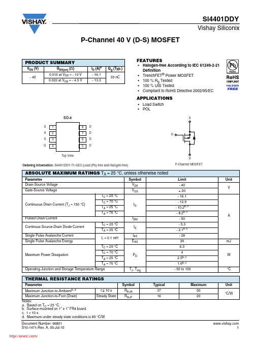
• Halogen-free According to IEC 61249-2-21 Definition • TrenchFET® Power MOSFET • 100 % Rg Tested • 100 % UIS Tested • Compliant to RoHS Directive 2002/95/EC
Si4401DDY
Vishay Siliconix
DMP4015SPS---PMOS Datasheet(数据表)

Symbol BVDSS IDSS IGSS VGS(th) RDS (ON) |Yfs| VSD Ciss Coss Crss RG Qg Qgs Qgd tD(on) tr tD(off) tf
Min -40 -1.5
nA V mΩ S V
pF Ω nC
ns
6. Device mounted on FR-4 PC board, with minimum recommended pad layout, single sided. 7. Device mounted on FR-4 substrate PC board, 2oz copper, with thermal bias to bottom layer 1inch square copper plate 8. UIS in production with L = 0.1mH, TJ = +25°C 9 .Short duration pulse test used to minimize self-heating effect. 10. Guaranteed by design. Not subject to production testing.
DMP4015SPS
Green
40V P-CHANNEL ENHANCEMENT MODE MOSFET POWERDI®
Product Summary
V(BR)DSS RDS(on) max 11mΩ @ VGS = -10V 15mΩ @ VGS = -4.5V ID TA = +25°C -17.0A -14.5A
Electrical Characteristics (@TA = +25°C, unless otherwise specified.)
TSOP1240TB1中文资料
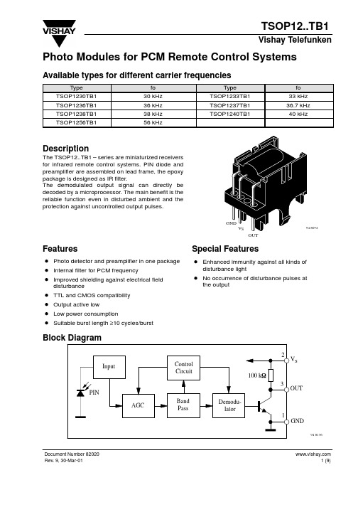
Photo Modules for PCM Remote Control Systems Available types for different carrier frequenciesTypeTSOP1230TB1TSOP1236TB1TSOP1238TB1TSOP1256TB1DescriptionThe TSOP12..TB1 – series are miniaturized receiversfor infrared remote control systems. PIN diode andpreamplifier are assembled on lead frame, the epoxypackage is designed as IR filter.The demodulated output signal can directly bedecoded by a microprocessor. The main benefit is thereliable function even in disturbed ambient and theprotection against uncontrolled output pulses.UnitVmAVmA°C°C°CmW°CMax Unit 1.5mAmA 5.5VDocument Number 82020Suitable Data FormatThe circuit of the TSOP12..TB1 is designed in that way that unexpected output pulses due to noise or disturbance signals are avoided. A bandpassfilter, an integrator stage and an automatic gain control are used to suppress such disturbances.The distinguishing mark between data signal and disturbance signal are carrier frequency, burst length and duty cycle.The data signal should fullfill the following condition:•Carrier frequency should be close to center frequency of the bandpass (e.g. 38kHz).•Burst length should be 10 cycles/burst or longer.•After each burst which is between 10 cycles and 70cycles a gap time of at least 14 cycles is neccessary.•For each burst which is longer than 1.8ms a corresponding gap time is necessary at some time in the data stream. This gap time should be at least 4times longer than the burst.•Up to 800 short bursts per second can be received continuously.Some examples for suitable data format are:NEC Code (repetitive pulse), NEC Code (repetitive data), Toshiba Micom Format, Sharp Code, RC5Code, RC6 Code, R–2000 Code.When a disturbance signal is applied to the TSOP12..TB1 it can still receive the data signal.However the sensitivity is reduced to that level that no unexpected pulses will occure.Some examples for such disturbance signals which are suppressed by the TSOP12..TB1 are:•DC light (e.g. from tungsten bulb or sunlight)•Continuous signal at 38kHz or at any other frequency•Signals from fluorescent lamps with electronic ballast with high or low modulation (see Figure A or Figure B).05101520time [ms]Figure A: IR Signal from Fluorescent Lamp with low Modulation05101520time [s]Figure B: IR Signal from Fluorescent Lamp with high Modulation2.0/m ) Figure 4. Sensitivity vs. Electric Field Disturbances1 kHzE eV O V OH V OL Optical Test Signal (IR diode TSAL6200, I Output Signalt d1)E eOptical Test Signal Document Number 8202095 11339p20.40.200.20.40.60.60.90°30°10°20°40°50°60°70°80°1.00.80.7d rel – Relative Transmission Distance Figure 13. Vertical Directivity ϕy 95 11340p20.40.200.20.40.60.60.90°30°10°20°40°50°60°70°80°1.00.80.7d rel – Relative Transmission DistanceFigure 14. Horizontal Directivity ϕxDocument Number 82020Dimensions in mm96 1211810.4Document Number 82020Ozone Depleting Substances Policy StatementIt is the policy of Vishay Semiconductor GmbH to1.Meet all present and future national and international statutory requirements.2.Regularly and continuously improve the performance of our products, processes, distribution and operating systems with respect to their impact on the health and safety of our employees and the public, as well as their impact on the environment.It is particular concern to control or eliminate releases of those substances into the atmosphere which are known as ozone depleting substances (ODSs).The Montreal Protocol (1987) and its London Amendments (1990) intend to severely restrict the use of ODSs and forbid their use within the next ten years. Various national and international initiatives are pressing for an earlier ban on these substances.Vishay Semiconductor GmbH has been able to use its policy of continuous improvements to eliminate the use of ODSs listed in the following documents.1.Annex A, B and list of transitional substances of the Montreal Protocol and the London Amendments respectively2.Class I and II ozone depleting substances in the Clean Air Act Amendments of 1990 by the Environmental Protection Agency (EPA) in the USA3.Council Decision 88/540/EEC and 91/690/EEC Annex A, B and C (transitional substances) respectively.Vishay Semiconductor GmbH can certify that our semiconductors are not manufactured with ozone depleting substances and do not contain such substances.We reserve the right to make changes to improve technical design and may do so without further notice.Parameters can vary in different applications. All operating parameters must be validated for each customer application by the customer. Should the buyer use Vishay-Telefunken products for any unintended or unauthorized application, the buyer shall indemnify Vishay-Telefunken against all claims, costs, damages, and expenses, arising out of, directly or indirectly, any claim of personal damage, injury or death associated with such unintended or unauthorized use.Vishay Semiconductor GmbH, P .O.B. 3535, D-74025 Heilbronn, Germany Telephone: 49 (0)7131 67 2831, Fax number: 49 (0)7131 67 2423。
- 1、下载文档前请自行甄别文档内容的完整性,平台不提供额外的编辑、内容补充、找答案等附加服务。
- 2、"仅部分预览"的文档,不可在线预览部分如存在完整性等问题,可反馈申请退款(可完整预览的文档不适用该条件!)。
- 3、如文档侵犯您的权益,请联系客服反馈,我们会尽快为您处理(人工客服工作时间:9:00-18:30)。
Vishay SiliconixSiP12401Document Number: 73193Boost Controller For Double AA Cell or Li-Ion BatteryFor White LED ApplicationFEATURES•Voltage Mode Control with InternalFrequency Compensation• 1.8 V to 5.0 V Input Voltage Range •PWM Control with 600 kHz FixedSwitching Frequency•Analog Control of LED Intensity •Regulated Output Current•Integrated UVLO and Soft-Start •Logic Controlled Shutdown (< 1 µA) •High Efficiency: Typical 80 % •PowerPAK ® MLP33-6 PackageAPPLICATIONS•White LED Backlighting •LCD Bias Supplies •Handheld Devices •Digital Cameras•Portable ApplicationsDESCRIPTIONSiP12401 is a boost controller I C for double cell NiMH or Alkaline battery and Li I on battery, which can drive white LEDs connected in series to provide backlight in hand-held devices. Series connection of the LEDs provides identical LED currents resulting in uniform brightness and eliminating the need for ballast resistors. For best efficiency performance, the SiP12401 is designed to operate in PWM mode with 600 kHz switching. The voltage-mode PWM design is internally compensated, reducing the external parts count. It accepts input voltages from 1.8 V to 5.0 V. The LED current can be adjusted externally for its brightness control. SiP12401 features low shutdown current of under 1 µA.SiP12401 is available in a lead (Pb)-free 6-pin, PowerPAK MLP33 package and is specified to operate over the industrial temperature range of - 40 °C to 85 °C.TYPICAL APPLICATION CIRCUIT Document Number: 73193Vishay SiliconixSiP12401Notes:a. Derate 20 mW/°C above 70 °C.b. Device Mounted with all leads soldered or welded to PC board.Stresses beyond those listed under “Absolute Maximum Ratings” may cause permanent damage to the device. These are stress ratings only, and functional operation of the device at these or any other conditions beyond those indicated in the operational sections of the specifications is not implied. Exposure to absolute maximum rating conditions for extended periods may affect device reliability.Notes:a. Full = - 40 to 85 °C.b. The algebraic convention whereby the most negative value is a minimum and the most positive a maximum (- 40° to 85 °C).c. Typical values are for DESIGN AID ONLY, not guaranteed nor subject to production testing.ABSOLUTE MAXIMUM RATINGS (all voltages referenced to GND = 0 V)Parameter Limit UnitInput Voltage, V IN - 0.3 to 6V EXT Voltage - 0.3 to V IN + 0.5XSHD Voltage - 0.3 to V IN + 0.5FB Voltage- 0.3 to V IN + 0.5Maximum Junction T emperature 150°C Storage T emperature- 55 to 150Operating Junction T emperature 125Power Dissipation a PowerPAK MLP33-6 (T A = 70 °C)a 1100mW Thermal Resistance bPowerPAK MLP33-650°C/W RECOMMENDED OPERATING RANGE (all voltages referenced to GND = 0 V)Parameter Limit UnitInput Voltage, V IN 1.8 to 5V XSHD, EXT Voltage 0 V to V IN LX Voltage 0 to V OUT + 0.5FB Voltage0 to 5Operating Temperature Range- 40 to 85°C SPECIFICATIONS aParameter Symbol Test Conditions Unless SpecifiedV IN = 3 V , T A = 25 °C Temp a LimitsUnitMin b Typ cMax b Input Voltage V IN Full 1.85V UVLOV UVLO Full1.65 1.77UVLO Hysteresis V UVLOHYST0.1Feedback Voltage V FB 0.2910.30.309Full0.2820.318Feedback Input Current I FB V FB = 0.3 V1nA Maximum PWM Duty Cycle MAXDTY 7785%PWM Switching Frequency f OSC Full425600775kHz Quiescent Current I Q V FB = 0.4 V 200300µA Stand-By Current I STB XSHD = 0 VFull 1XSHD Input High Level V XSHDH Full 1.2V XSHD Input Low Level V XSHDL Full0.2EXT High On Resistance R EXTH I EXT = 10 mA 35ΩEXT Low On ResistanceR EXTL30Document Number: Vishay SiliconixSiP12401PIN CONFIGURATION AND TRUTH TABLEPIN FUNCTIONSXSHD (Pin 1)XSHD is the logic controlled shutdown input pin. WhenXSHD is low, the IC is shutdown and it’s quiescent current is less than 1 µA. When XSHD is high, the I C is working in normal operation.V IN (Pin 2)V IN is the pin connected to battery input voltage. The IC gets its power supply from V IN .FB (Pin 3)FB is the feedback pin of the output voltage via resistor divider. FB is about 0.3 V and its difference from 0.3 V reference voltage is amplified by the error amplifier.AGND (Pin 4)AGND is the pin for ground of controlling circuit.PGND (Pin 5)PGND is the pin for ground of the internal power MOS driver.EXT (Pin 6)EXT is the output pin of internal driver. It’s connected to the gate of external power MOSFET.ORDERING INFORMATIONPart Number Temperature RangeMarking SiP12401DMP-T1-E3- 40 to 85 °C2401PIN DESCRIPTIONPin NumberName Function1XSDH Logic Controlled Shutdown Input, XSHD = High: Normal Operation, XSHD = Low: Shutdown2V IN Battery Input Voltage 3FB Output Voltage Feedback Pin 4AGND Signal Ground 5PGND Power Ground6EXTDrive Pin for External Power MOSVishay SiliconixSiP12401FUNCTIONAL BLOCK DIAGRAM DETAILED OPERATIONSiP12401 is a 600 kHz boost controller IC, packaged in 6-pin MLP33, for white LED applications. I t features fixed frequency voltage mode PWM control with internal frequency compensation. With the low r DS(on) external power MOSFET, this device maintains high efficiency over a wide range of load current.Soft-StartDuring soft-start, the loop compensation guarantees the slow increase of the output voltage and inrush current, so that no large voltage overshoot and inrush current occur when the soft-start is ended.PWM operationAfter soft-start, the device is working in PWM operation with a fixed frequency of 600 kHz.APPLICATION INFORMATIONWhite LED Brightness ControlThe current of white LED can be adjusted by PWM signal on the XSHD pin or by a variable dc voltage to control its brightness, (see Figure 1.) As control voltage V CTRL increases, the voltage drop on R2 increases and the voltage drop on R1 decreases. Thus, the LED current decreases. The selection of R2 and R3 will make the current from V CTRL much smaller than LED current and much larger than the FB pin bias current. Document Number: 73193Document Number: Vishay SiliconixSiP12401TYPICAL CHARACTERISTICSShutdown Threshold vs. Temperature Document Number: 73193Vishay SiliconixSiP12401TYPICAL WAVEFORMSVishay Siliconix maintains worldwide manufacturing capability. Products may be manufactured at one of several qualified locations. Reliability data for Silicon Technology and Package Reliability represent a composite of all qualified locations. For related documents such as package/tape drawings, part marking, and reliability data, see /ppg?73193.Figure 1. PWM Dimming Control200 Hz 50 % Duty Cycle PWM Signal on XSHD Pin1 ms/divV IN = 3.6 VFour LEDs in seriesFigure 3. Switching Waveforms: V IN , V OUT and V EXT V IN = 3.6 V, L = 22 µH, C OUT = 4.7 µF, Four LEDs in Series1 µ s /divDisclaimer Legal Disclaimer NoticeVishayAll product specifications and data are subject to change without notice.Vishay Intertechnology, Inc., its affiliates, agents, and employees, and all persons acting on its or their behalf (collectively, “Vishay”), disclaim any and all liability for any errors, inaccuracies or incompleteness contained herein or in any other disclosure relating to any product.Vishay disclaims any and all liability arising out of the use or application of any product described herein or of any information provided herein to the maximum extent permitted by law. The product specifications do not expand or otherwise modify Vishay’s terms and conditions of purchase, including but not limited to the warranty expressed therein, which apply to these products.No license, express or implied, by estoppel or otherwise, to any intellectual property rights is granted by this document or by any conduct of Vishay.The products shown herein are not designed for use in medical, life-saving, or life-sustaining applications unless otherwise expressly indicated. Customers using or selling Vishay products not expressly indicated for use in such applications do so entirely at their own risk and agree to fully indemnify Vishay for any damages arising or resulting from such use or sale. Please contact authorized Vishay personnel to obtain written terms and conditions regarding products designed for such applications.Product names and markings noted herein may be trademarks of their respective owners.Document Number: 分销商库存信息: VISHAYSIP12401DMP-T1-E3。