12511HB-11RR-K中文资料
霍尼韦尔(Honeywell)HPL-ED2011 V2.0 EN(UX111)过载继电器ZB150

These tripping characteristics are mean values of the spread at 20 °C ambient temperature in a cold state. Tripping time depends on response current. On devices at operating temperature the tripping time of the overload relay drops to approx. 25 % of the read value. Specific characteristics for each individual setting range can be found in the manual.
mm2
1 x (4 - 70)
2 x (4 - 50)
mm2
1 x (16…50)
2 x (16…50)
07/21/2011
HPL-ED2011 V2.0 EN (UX111)
2/5
Solid or stranded
AWG
2/0
Terminal screw
M10
Tightening torque
Nm
10
Tools
Hexagon socket-head spanner
Auxiliaryandcontrolcircuits
Rated impulse withstand voltage
SW
mm
5
Uimp
V
6000
Overvoltage category/pollution degree
III/3
Rated insulation voltage
Turck双检测面电感式传感器说明书
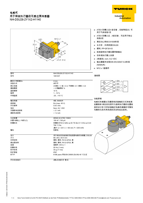
T 04:43:35+02:00型号NI4-DSU26-2Y1X2-H1140货号1051007额定工作距离Sn 4 mm 安装方式非齐平修正系数37#钢 = 1; 铝 = 0.3; 不锈钢= 0.7; 黄铜 = 0.4重复精度ð 2 满量程的 %温度漂移10 %磁滞1…10 %环境温度-25…+70 °C 输出性能4线, NAMUR 阀控制Exi (max. 45 V)开关频率0.05 kHz电压Nom. 8.2 VDC 无激励电流损耗ï 2.1 mA 激励电流损耗ð 1.2 mA认证依据KEMA 02 ATEX 1090X 内置 电感(L ) / 电容 (C )150 nF / 150 µH防爆标志防爆标识为II 2 G/Ex ia IIC T6 Gb /II 1 D Ex ia D 20T95 °C Da(最大 U = 20 V, I = 60 mA, P = 200 mW)警告防静电设计用于阀位回讯检测的双检测面电感式传感器, DSU26尺寸68 x 60 x 35.4 mm外壳材料塑料, 塑料, PA12-GF20, 黄感应面材料塑料, 塑料, PA12-GF20, 黑连接接插件, M12 x 1防震动性55 Hz (1 mm)防冲击性30 g (11 ms)防护等级IP67MTTF 6198 years 符合SN 29500 (Ed.99) 40 °C认证开关状态指示2路LED指示灯 黄/红sATEX 防爆认证II 组设备,设备等级2G. 可用于气体危险1区sATEX 防爆认证,II组设备,可应用于粉尘危险0区s 满足SIL2和IEC61508标准s 长方形,外壳类型DSU26s 塑料, PP -GF30-V0s 检测旋转执行器位置两路输出s 在标准执行器上安装s 2线直流, nom. 8.2 VDCs输出遵循本安型DIN EN 60947-5-6标准(NAMUR)sM12 x 1接插件接线图功能原理电感式传感器以无磨损和非接触的方式来检测金属物体 阀位回讯是专为旋转执行器的位置检测而设计的 它将非接触式电感传感器的可靠性与模块化的外壳系统的灵活性结合起来。
负温度系数热敏电阻器:SCK 系列

16
2.5
0.471
√√√√√
SCK10202□
20
2
0.646
√√√√√
SCK10222□
22
2
0.659
√√
√√
SCK10252□
25
2
0.674
√√√√√
SCK10302□
30
SCK10472□
47
2
0.700
2
0.720
√√√√√ √√√√√
SCK10502□
50
2
0.813
√√√√√
SCK10801□
UL
安规认证 cUL CSA TUV CQC
西格尼特8550-1流量变送器手册说明书

WARNING!• Remove power to unit before wiring input and out-put connections.• Follow instructions carefully to avoid personalinjury.Signet 8550-1 Flow TransmitterContents1. Specifications2. Installation3. E lectrical Connections4. Menu FunctionsCurrent output:• 4 to 20 mA, isolated, fully adjustable and reversible• Max loop impedance: 50 Ω max. @ 12 V325Ω max. @ 18 V600Ω max. @ 24V• Update rate: 100 ms• Accuracy: ±0.03 mAOpen-collector output, optically isolated:• 50 mA max. sink, 30 VDC maximum pull-up voltage.• Programmable for:• High or Low setpoint with adjustable hysteresis• Pulse operation (max rate: 300 pulses/min).Environmental• Operating temperature: -10 to 70°C (14 to 158°F)• Storage temperature: -15 to 80°C (5 to 176°F)• Relative humidity: 0 to 95%, non-condensing• Maximum altitude: 2000 m (6562 ft)• Insulation category: II• Pollution degree: 2Standards and Approvals• CSA, C E, UL listed• Immunity &E missions: E N61326• Manufactured under ISO 9001 and ISO 14001GeneralCompatibility: Signet Flow Sensors (w/freq out)Enclosure:• Rating: N E MA 4X/IP65 front• Case: PBT• Panel case gasket: Neoprene• Window: Polyurethane coated polycarbonate• Keypad: Sealed 4-key silicone rubber• Weight: Approx. 325g (12 oz.)Display:• Alphanumeric 2 x 16 LCD• Update rate: 1 second• Contrast: User selected, 5 levels• Display accuracy: ±0.5% of reading @ 25ºC• Thermal sensitivity shift: ±0.005% of reading per ºCElectrical• Power: 12 to 24 VDC ±10%, regulated61 mA max currentSensor Input:• Range: 0.5 to 1500 Hz• Sensor power: 2-wire: 1.5 mA @ 5 VDC ± 1%3 or4 wire: 20 mA @5 VDC ± 1%Optically isolated from current loop• Short circuit protected2. InstallationProcessPro transmitters are available in two styles: panel mount and fi eld mount. The panel mount is supplied with the necessary hardware to install the transmitter. This manual includes complete panel mounting instructions.Field mounting requires one of two separate mounting kits. The 3-8051 integral kit joins the sensor and instrument together into a single package. The 3-8050 Universal kit enables the transmitter to be installed virtually anywhere.Detailed instructions for integral mounting or other fi eld installation options are included with the 3-8051 Integral kit or the 3-8050 Universal kit.SIDE VIEWField Mount w/8051 Integral kitSIDE VIEWField Mount w/8050 Universal basePanel MountSIDE VIEWFRONT VIEWField Mount &Panel Mount1. Specifi cationsDimensions3-8550.090-1 J 4/05 English*3-8550.090-1*English2Signet 8550-1 Flow Transmitter3. Electrical ConnectionsCaution: Failure to fully open terminal jaws before removing wire may permanently damage instrument.Wiring Procedure1. Remove 0.5 - 0.625 in. (13-16 mm) of insulation from wire end.2. Press the orange terminal lever downward with a small screwdriver to open terminal jaws.3. Insert exposed (non-insulated) wire end in terminal hole until it bottoms out.4. Release orange terminal lever to secure wire in place. Gently pull on each wire to ensure a good connection.Wiring Removal Procedure1. Press the orange terminal lever downward with a small screwdriver to open terminal jaws.2. When fully open, remove wire from terminal.Installation2. Place gasket on instrument, and install in panel.3. Slide mounting bracket over back of instrument until quick-clips snap into latches onside of instrument.4. To remove, secure instrument temporarily with tape from front or grip from rear ofinstrument. DO NOT RELEASE.Press quick-clips outward and remove.3Signet 8550-1 Flow TransmitterStand-alone application, no current loop usedTransmitterAUXILIARY power is used only if the flow sensor requires more than 1.5 mA current.For Signet sensors this is limited to the following products: 2000, 2507, 2551, open collector input signals3.1 System Power/Loop Connections3.2 Sensor Input ConnectionsWiring Tips:• Do not route sensor cable in conduit containing AC power wiring.Electrical noise may interfere with sensor signal.• Routing sensor cable in grounded metal conduit will help preventelectrical noise and mechanical damage.• Seal cable entry points to prevent moisture damage.• Only one wire should be inserted into a terminal. Splice double wiresoutside the terminal.Maximum cable length is 200 ft. for 515/8510-XX, 525 , 2517 and any sinusoidal fl ow signal.Maximum cable length is 1000 ft. for2536/8512-XX, 2540, vortex, and any open collector fl ow signal.No Aux Power515/3-8510-XX 525210025172536/3-8512-XX 25407000 VortexAux Power200025072551Open Coll. InputTerminalsSensr Gnd (SHIELD)Sensr IN (RED)Sensr V+(BLACK)9874Signet 8550-1 Flow TransmitterMonitor the Permanent Totalizer value.Monitor the 4-20 mA Loop output.Monitor date for scheduled maintenance or date of last calibration. (See description in Calibrate Menu.)HysteresisLow SetpointOutput energized Output relaxedHigh SetpointVIEW menu• During normal operation, the ProcessPro displays the VIEW menu.• When using the CALIBRATE or OPTIONS menus, the ProcessPro will return to the VIEW menu if no activityoccurs for 10 minutes.• To select the item you want displayed, press the UP or DOWN arrow keys. The items will scroll in acontinuous loop. Changing the display selection does not interrupt system operations.• No key code is necessary to change display selection.• Output settings cannot be edited from the VIEW menu.3.3 Open Collector OutputThe Open collector output can be used as a switch that responds when the fl ow rate moves above or below a setpoint, or it can be used to generate a pulse that is relative to the fl ow volume or to the fl ow rate.• LowOutput triggers when the fl ow rate is less than the setpoint.The output will relax when the fl ow rate moves above the setpoint plus the hysteresis value.• HighOutput triggers when the fl ow rate is greater than the setpoint.The output will relax when the fl ow rate drops below the setpoint plus the hysteresis value.• FrequencyOutput is a pulse stream that is based on the input fl ow sensor signal. Set for 1 (input frequency = output frequency). Set for even numbers (2, 4, 6, 8 . . . . 254 maximum) to scale output frequency.• PulseOutput is a pulse based on the volume of fl uid that passes the sensor. Set any value from 0.0001 to 99999.The output may be disabled (Off) if not used.View MenuDisplayDescription0.0 GPMTotal: 12345678 >Monitor the fl ow rate and the resettable totalizer. Press the RIGHT ARROW key to reset the totalizer. If the Reset is locked, you will need to enter the Key Code fi rst. Lock or Unlock the totalizer in the OPTIONS menu. This is the permanent View display.All of the displays below are temporary. After ten minutes the display will return to the permanent display.Perm: 12345678GallonsLoop Output:12.00 mALast CAL:04-20-065Signet 8550-1 Flow Transmitter Notes on Steps 5 and 6:• All output functions remain active during editing.• Only the fl ashing element can be edited.• RIGHT ARROW key advances the fl ashing element in a continuous loop.• Edited value is effective immediately after pressing ENTER key.• If no key is pressed for 10 minutes unit will restore the last saved value and return to step 3.• Step 6 (pressing ENTER key) always returns you to Step 3.• Repeat steps 3-6 until all editing is completed.ProcessPro Editing Procedure:Step 1. Press and hold ENTER key:• 2 seconds to select the CALIBRATE menu • 5 seconds to select the OPTIONS menu.Step 2. The Key Code is UP-UP-UP-DOWN keys in sequence.• After entering the Key Code, the display will show the fi rst item in the selected menu.Step 3. Scroll menu with UP or DOWN arrow keys.Step 4. Press RIGHT ARROW key to select menu item to be edited.• The fi rst display element will begin fl ashing.Step 5. Press UP or DOWN keys to edit the fl ashing element.• RIGHT ARROW key advances the fl ashing element.6 Signet 8550-1 Flow TransmitterThe first three characters set the Flow Rate units of measure. They have no effect on calculations. They may be any alpha or numeric character, upper or lower case.The last character sets the Flow rate Timebase. Select S (seconds), M (minutes), H (hours) or D (days).This setting tells the transmitter how to convert the input frequency from the flow sensor into a fl ow rate. The K-factor is unique to the sensor model and to the pipe size and schedule. Refer to data in the sensor manual for the correct value. Limits: 0.0001 to 99999. (The K-factor cannot be set to 0)This setting identifi es the Totalizer units. It has no effect on any calculation. It serves as a label only. Each character can be any alpha or numeric selection, upper or lower case.This setting tells the transmitter how to convert the input frequency from the flow sensor into a volumetric total. It also is used as the basis for the Open Collector pulse mode.The setting is usually the same as the Flow K-factor, or different by x10 or x100. Limits: 0.0001 to 99999. (The K-factor cannot be set to 0)Select the minimum and maximum values for the 4-20 mA Current loop output. The 8550 will allow any values from 0.0000 to 99999.Select the desired mode of operation for the Open Collector output. Options available are High, Low, volumetric Pulse, or Frequency. The signal may be disabled (Off) if not used.In Low or High Mode, the Open Collector output will be activated when the Flow rate reaches this value. Be sure to modify this setting if you change the Flow Units.The Open Collector output will be deactivated at Setpoint ± Hysteresis, depending on High or Low Setpoint selection. (See details on page 4.)In Pulse mode, the Open collector output will generate one pulse when this volume of fl ow passes the sensor. The measurement is based on the Total K-factor. The 8550 will allowany value from 0.0001 to 99999.In Pulse mode, this setting defi nes the duration of the Open Collector output pulse. The 8550 allows any value from 0.1 seconds to 999.9 seconds.In Frequency mode, the Open Collector output will simulate the sensor frequency, divided by this setting. Set for 1 (input frequency = output frequency). Set for even numbers(2, 4, 6, 8 . . . 254 maximum) to scale output frequency.Use this “note pad” to record important dates, such as annual recertifi cation or scheduled maintenance.Calibrate MenuDisplay(Factory settings shown)DescriptionFlow Units:GPM >Flow K-Factor:60 >Total Units:Gallons >Total K-Factor 60 >Loop Range: GPM000.00 → 100.00 >Output Mode:Low > Output Setpnt:10.0 GPM >Output Hys:5.0 GPM >Output Volume:100.00 Gallons >Output PlsWdth:0.1 Seconds >Output Freq.:Divide by1 >Last CAL:4-20-06Options Menu10 s2 s20 s30 s40 s50 s60 s70 svery quickly. (Solid blue line)NOTE: The SENSITIVITY function is ineffective if the AVERAGING function is set to zero (seconds).Signet 8550-1 Flow Transmitter7“- - - - -”“Pulse Overrun”“Value must be more than 0”Open Collector is always activatedFlow rate exceeds display capability• Open Collector pulse rate exceeds maximum of 300 pulses per minute.• Pulse width set too wide.K-factors cannot be set to 0.• Hysteresis value too large • Defective transmitter• Increase Flow units time base • Move fl ow decimal one place to the right• Increase Pulse volume setting • Decrease pulse width setting. • Reduce system fl ow rateEnter K-factor from 0.0001 to 99999• Change the hysteresis value• Replace transmitterGeorge Fischer Signet, Inc. 3401 Aerojet Avenue, El Monte, CA 91731-2882 U.S.A. • Tel. (626) 571-2770 • Fax (626) 573-2057For Worldwide Sales and Service, visit our website: • Or call (in the U.S.): (800) 854-40903-8550.090-1 J 4/05 English © George Fischer Signet, Inc. 2002 TroubleshootingDisplay ConditionSuggested SolutionsPossible CausesOrdering InformationMfr. Part No.CodeDescription3-8550-1159 000 047 Flow transmitter, Field mount 3-8550-1P 159 000 048 Flow transmitter, Panel mount3-8550-2 159 000 049 Flow transmitter, Field mount with relays 3-8550-2P 159 000 050 Flow transmitter, Panel mount with relays3-8550-3 159 000 051 Flow transmitter, Field mount with dual input/output 3-8550-3P159 000 052Flow transmitter, Panel mount with dual input/outputAccessoriesMfr. Part No.CodeDescription3-8050 159 000 184 Universal mounting kit 3-8051 159 000 187 Flow Integral Mnt NPT 3-8050.395 159 000 186 Splashproof rear cover 3-8050.396 159 000 617 RC Filter kit (for relay use)3-0000.596 159 000 641 Heavy duty wall mount bracket 3-5000.598 198 840 225 Surface Mount Bracket3-5000.399 198 840 224 5 x 5 inch adapter plate for Signet retrofi t3-9000.392 159 000 368 Liquid tight connector kit for rear cover (includes 3 connectors)3-9000.392-1 159 000 839 Liquid tight connector kit, NPT (1 piece)3-9000.392-2 159 000 841 Liquid tight connector kit, PG13.5 (1 piece)7300-7524 159 000 687 24 VDC Power Supply 7.5 Ω, 300mA 7300-1524 159 000 688 24 VDC Power Supply 15 Ω, 600mA 7300-3024 159 000 689 24 VDC Power Supply 30 Ω, 1.3 A 7300-5024 159 000 690 24 VDC Power Supply 50 Ω, 2.1 A 7300-1024 159 000 69124 VDC Power Supply 100 Ω, 4.2 A。
美瑞克仪器直流电阻测试仪RK2511AL BL系列使用说明书

美瑞克仪器MEIRUIKE INSTRUMENTManua l使用说明书深圳市美瑞克电子科技有限公司版本历史:由于说明书中可能存在错误或遗漏、改进和完善仪器功能、更新技术及升级软件,本说明书将做相应的调整和修订、不断完善以利于使用。
请关注所使用的软件版本及说明书版本。
2020年12月 VER1.02021年07月 VER2.0(地址更新)2021年09月 VER3.0(售后电话变更)2021年12月 VER4.0(修改单位符号K大小写、更正语句错误、添加附件型号)声明:本公司可能对该产品的性能、功能、软件、结构、外观、附件、包装以及说明书等进行完善和提高,如有修改,恕不另行通知!如造成疑惑,请与本公司联系。
目录一、产品概述2二、产品规格...........................................................................................................22.1RK 2511AL 系列简介:.................................................................................22.2测试范围.......................................................................................................22.3测试量程...................................................................................................22.4显示范围...................................................................................................2.5测试速度...................................................................................................2.6触发方式...................................................................................................三、参数规格及相应说明.......................................................................................3.1具体参数...................................................................................................3.2一般技术指标...............................................................................................3.3测试端、基准端说明...................................................................................四、面板、后板介绍...............................................................................................4.1前面板功能介绍...........................................................................................4.2后面板功能介绍............................................................................................五、操作说明.......................................................................................................5.1上电启动...................................................................................................5.2开始测试.....................................................................................................5.3选择测试速度.............................................................................................5.4选择测试量程.............................................................................................5.5清零标准.....................................................................................................5.6功能菜单.....................................................................................................5.7后面板HANDLER 接口介绍(选配)........................................................5.8串行RS-232标准接口(选配)..............................................................六、串口通讯指令(仅适用于RK2511ALR )七、常见故障及维护.............................................................................................7.1常见故障排除..............................................................................................7.2更换保险说明.................................................................................................7.3产品保修说明............................................................................................................................................................................................................334566788888991113152020207.4装箱清单. (21)203336.1指令格式简要说明..............................................................................................6.2基本指令..............................................................................................附录:选型表.............................................................................................151591........................................................一、产品概述RK2511AL/BL 系列是一款经济实用的直流电阻测试仪,具有更广的测试范围:0.01m Ω~200.0KΩ,最大显示数5000数。
特灵中央空调设备参数表
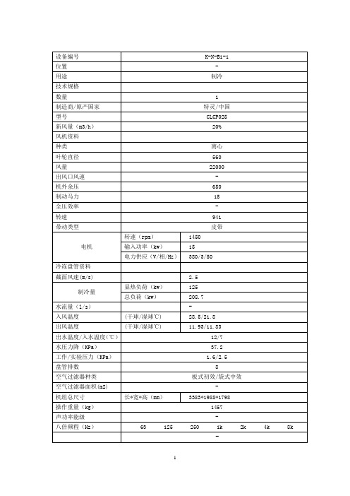
8
空气过滤器种类
板式初效/袋式中效
空气过滤器面积(m2)
-
机组总尺寸
长*宽*高(mm)
3383*1988*1798
操作重量(kg)
1457
声功率能级
-
八倍频程(Hz)
63 125 250 1k 2k 4k 8k
设备编号
K-N-B1-13
位置
-
用途
制冷
技术规格
数量
1
制造商/原产国家
特灵/中国
型号
全压效率
-
转速
1287
带动类型
皮带
电机
转速(rpm)
1450
输入功率(kw)
11
电力供应(V/相/Hz)
380/3/50
冷冻盘管资料
截面风速(m/s)
2.5
制冷量
显热负荷(kw)
112.6
总负荷(kw)
77
水流量(l/s)
-
入风温度
(干球/湿球℃)
28.5/21.8
出风温度
(干球/湿球℃)
12.42/12.3
设备编号
K-N-B1-6
位置
-
用途
制冷
技术规格
数量
1
制造商/原产国家
特灵/中国
型号
CLCP016
新风量(m3/h)
20%
风机资料
种类
离心
叶轮直径
450
风量
16000
出风口风速
-
机外余压
500
制动马力
11
全压效率
-
转速
1052
带动类型
皮带
马可尼光端机培训教材

目录第一章 SDH原理 (2)第二章马可尼SDH光端机 (5)第一节SMA16-64产品简介 (5)第二节单元描述 (6)第三节单元卡介绍 (10)第四节功能概述 (13)第三章设备预防性试验 (14)第一节设备预防性试验项目 (14)第四章设备日常巡视项目 (19)第五章设备运行维护注意事项 (22)第一章 SDH原理一、SDH定义:同步数字序列SDH(Synchronous Digital Hierarchy),是有关通过物理传输网络,传送适配的的净负荷标准化数字传输结构的一个系列集。
二、SDH等级速率:ITU-TG.707中规定了SDH的各等级速率。
其中最基本的模块是STM-1,速率为155。
52Mbit/s,更高等级的是STM-N,其中N为正整数,即N=1,4,16,64。
三、SDH中STM—N 帧结构SDH帧结构是一种矩形块状结构,由270×N列和9行字节组成,每个字节有8bit。
帧中字节是从左往右,从上往下按行进行传输的,传完一帧再传下一帧,每秒共传8000帧。
每个基本帧的周期为125μs,即帧频为8kHz,每个字节为8bit,则STM-1的速率为: Fb=8000×270×9×8=155520000bit/s=155。
52M bit/s由下图可以看出,SDH帧结构大体可以分为三个区域(1)段开销区域:为保证信息净负荷正常灵活传输所必需的附加字。
(2)管理单元指针:用来指示信息净负荷的第一个字节在STM-N帧内准确的位置,以便在接收端正确分解的指示符。
(3)信息净负荷区域:帧结构中存放信息的区域.三、四、SDH复用基本概念:(1)映射:将各支路适配进相应的VC中称为映射。
(2)复接:将多个低阶通道层信号适配到高阶通道,或将多个高阶通道信号适配进复接段的称为复接。
(3)定位:将VC放进支路单元或管理单元,同时将其与帧参考点的偏差也作为信息结合进去的过程为定位。
各种电阻的特性

各种电阻的特性
碳膜电阻器(RT)
材料:高温下将有机化合物(烷,苯等碳氢化合物)热分解产生的碳积在陶瓷肌体表面。
碳膜电阻器阻值范围宽,由良好的稳定性,温度系数不大且是负值,是目前应用最广泛的电阻器。
超小型碳膜电阻:RT13 功率:0.125W 阻值范围:1-1M 允差:G,J,K环境温度范围:-55---125C 额定温度70 C 最大工作电压:150V温度系数:
-400---1500PPM 最大重量:0.1G
碳膜电阻:RT-0.25 功率:0.25W 阻值范围:10-5.1M 允差:J,K环境温度范围:-55---100C 额定温度40 C 最大工作电350V 温度系数:
-600---1200PPM 最大重量:1.5G
碳膜电阻:RT-1 功率:1W 阻值范围:27-10M 允差:J,K
环境温度范围:-55---100C 额定温度40 C 最大工作电压:700V温度系数:-600---1200PPM 最大重量:3.4G
金属膜电阻(RJ)
材料:通过真空蒸发或阴极溅射,沉积在陶瓷肌体表面上一层很薄的金属或合金膜。
特点:金属膜电阻比碳膜电阻的精度高,稳定性好,噪声,温度系数小,金属膜电阻由于结构不均匀,因此使他的脉冲负载能力差。
RJ13 功率:0.125W 阻值范围:100-510K 允差:,J,K
最大工作电压:150V 温度系数:+-500PPM 最大重量:0.1G。