ZFUR20A-A中文资料(SunLED)中文数据手册「EasyDatasheet - 矽搜」
ESC60HREF中文资料(List Unclassifed)中文数据手册「EasyDatasheet - 矽搜」

106.68 109.22 121.92 124.46 129.54 149.86
B
+_ 0.20
12.70 15.24 17.78 20.32 22.86
27.94 33.02 35.56 40.64 45.72 48.26
50.80 53.34 58.42 60.96 66.04 68.58
间隙
#4螺丝
间隙
孔(H)
螺纹
INSERT (I)
浮动
BOBBIN (F)
否安装耳
(N)
.125 [3.18] .135 [3.43]
侧面安装
(S)
芯片中文手册,看全文,戳
材料(绝缘层/触点)
E = PBT /磷青铜(标准) H = PBT /铍铜 R = PPS /磷青铜 A = PPS /铍铜
A
+_.008
0.300 0.400 0.500 0.600 0.700
0.900 1.100 1.200 1.400 1.600 1.700
1.800 1.900 2.100 2.200 2.400 2.500
2.700 2.900 3.000 3.400 3.500 3.900
4.200 4.300 4.800 4.900 5.100 5.900
17.15 24.77
19.69 27.31
22.23 29.85
24.77 32.39
27.31 34.93
32.39 40.01
37.47 45.09
40.01 47.63
45.09 52.71
50.17 57.79
ED15M44SLEZ中文资料(Positronic)中文数据手册「EasyDatasheet - 矽搜」
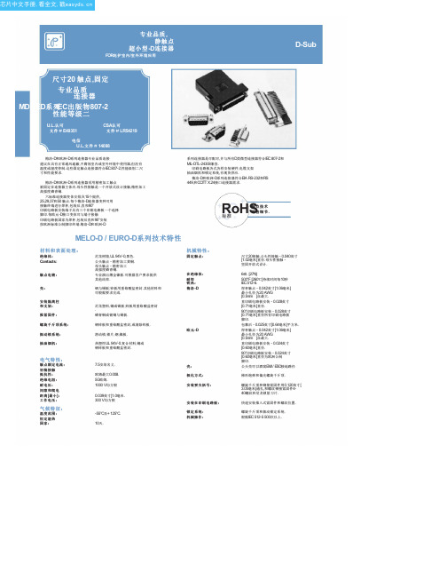
MD / ED系列
0.135 [3.43] 0.352 [8.94]
对于焊杯触点 ,指定 在步骤 4代码 2
订购信息.
典型型号: ED15M200T2Z
修正公头性和母头性提供偏光螺旋千斤顶. 指定订购信息步骤 7码 T6.
典型型号: MD15M200T6Z
直印刷电路板安装连接器
CODE NUMBER
HDC
6 0.375 [9.53] 0.360 [9.14]
指定订购信息步骤 6代码 F或 Q. F代表铁 素体电感和 Q为铁素体电感与推入式紧固件 .
L 90°印 刷 电 路 板 安 装 连 接 器
铁素体电感酒吧
A
0.135±0.005 [3.43±0.13]
Fixed female jackscrews
六标准连接器变体安排,9,15个提供, 25,29,37和50 触点.每个梅洛-D连接器变种可用 接触终端进行焊杯,包装后,直和90°
印刷电路板安装端子具有三个印刷电路板一个选择
脚印.每欧元-D接口变体可与端子接触 印刷电路板国家为焊杯,包装后直和90°安装 按欧洲标准公制脚印终端.梅洛-D和欧洲-D
钢与锡板;锌板用重铬酸盐密封.其他材料和 可根据要求完成.
尼龙塑料,铜或锡板;锌板用重铬酸盐密封 . 磷青铜或铍铜与锡板.
钢锌板和重铬酸盐密封,或清除锌板.
滑动锁,锁片,钢,镍板.
热塑性UL 94V-0.复合材料,铜或 钢锌板和重铬酸盐密封.
机械特性:
固定触点:
在绝缘体: 耐焊 铁热:
梅洛 -D
欧元 -D
可选壳件
与环球 FLOAT支架 [F]
0.120±0.010 [3.05±0.25]
A2-20PA-2.54DS中文资料

2.54mm Pitch High Density ConnectorA1 and A2 Seriess Features1. High Density MountingConnectors are aligned in the longitudinal direction on the 2.54 mm mesh board, so that no idle space can occur.2. Variation in Number of ContactsThe A1 series contains 16 types of 6 to 64 contacts, while the A2 series contains 20 types of 1 to 20 contacts,3. CompatibilityThe A1 series is compatible with HIF3B series cable side and HIF3H receptacle for wide applications.Note 1: Includes temperature rise caused by current flow.Note 2: The term "storage" refers to products stored for long period of time prior to mounting and use. Operating Temperature Range andHumidity range covers non conducting condition of installed connectors in storage, shipment or during transportation.s ApplicationsComputers, VTR, and other various kinds of electronic equipments Product Specificationss Materials Ordering Informationq Series Name:Aw Series No.:1 (double row)2 (single row)eNumber of contacts: A1...6, 8, 10, 12, 14, 16, 20, 24, 26,34, 40, 50, 60, 64A2...1, 2, 3, 4, 5, 6, 7, 8, 9, 10, 11, 12,13, 14, 15, 16, 17, 18, 19, 20r P: Pin headert A: Selective gold plated y Contact pitch : 2.54mm uContact type: DS : Right angle type DSA : Straight typeK Pin HeaderA 1 - 6 P A - 2.54 DSqrewtyq Series Name : Aw Series No. : 1 (double row)2 (single row)e Number of contacts: A1 : 8, 10, 12A2 : 5, 6r Contact alignment : A1 : D (double row)A2 : S (single row)t Contact pitch : 2.54mm yConnection type: C : crimpingK Crimping SocketA 1 - 12 D - 2.54 Cqterwyq Series Name : A w Series No. : 1eApplicable cable size 2226: AWG#22~ AWG#262630: AWG#26~ AWG#303236: AWG#32~ AWG#36r Packaging type SCFC : Reel SCC : BagK Crimping ContactA 1 - 3236 - SCFCqerwus A1 (Double Row)- Right Angle Types A1 (Double Row)- Straight Types A2 (Single Row)-DIP TypeK Straight typeK Right angle typeK Straight typeK Right angle typeK Double Row TypeKSingle Row TypeA1-*D-2.54CNote 1. No. 3 and 8 contacts can be polarized.A2-*S-2.54CNote 1. No. 4 contact can be polarized.Crimping ToolsSCC contactSCFC contacts Short PinsPerformance。
QDR20产品信息手册(定版)

目次1目的 (3)2范围 (3)3机组概述 (3)3.1机组技术参数 (3)3.2机组结构与组成 (4)4机组总成 (5)4.1整体台架 (6)4.2WJ6G1型燃气轮机 (6)4.3同步发电机 (7)4.4起动电机总成 (8)4.5输出轴联轴器总成 (8)4.6燃气轮机滑油系统 (9)4.6.1系统流程 (9)4.6.2系统主要部件 (10)4.7发电机滑油系统 (11)4.7.1系统流程 (11)4.7.2系统主要部件 (12)4.8燃料系统 (13)4.8.1系统流程 (13)4.8.2系统主要部件 (14)4.9主、辅支撑 (15)5主机箱体 (16)6箱体通风系统 (16)7进气过滤装置 (18)8进气消音装置 (19)9排气连接 (19)10燃机进气蜗壳 (20)11滑油冷却模块 (21)12箱体消防管路及灭火剂供应装置 (21)13控制系统 (21)14测量系统 (24)15马达控制中心 (25)16起动控制柜 (25)17直流系统 (25)1目的本信息手册阐述QDR20型燃气轮机发电机组的结构、系统组成及各系统的主要技术性能。
2范围本手册仅适用于QDR20型燃气轮机发电机组。
3机组概述QDR20型燃气轮机发电机组是以航空发动机改型的WJ6G1型燃气轮机为原动机,燃用液体或气体燃料,带动发电机发电并采用集装箱式布置形式的一种发电装置。
3.1机组技术参数机组在ISO标准条件(环境温度15℃,大气压力101.3kPa,相对湿度60%)及进排气损失为零条件下的性能参数如下:额定发电功率:2000kW额定输出电压: 6.3kV/10.5kV功率因数:0.8(滞后)额定转速:1000r/min频率:50Hz机组热耗:16.1MJ/kW·h噪声:机组外1米≤85dBNO x排放量:≤80mg/m3(焦炉煤气燃料)余热锅炉:蒸汽温度、压力、流量根据用户使用条件计算确定3.2机组结构与组成QDR20燃气轮机发电机组是以集装箱型式布置的一种机组。
VSA20A型型号的Eaton公司自动电路重合闸功能规范指南说明书

ReclosersFunctional Specification GuideType VSA20A RecloserPS280015EN1 of2 • Effective June 2017 • Supersedes May 1997 ©2017 Eaton. All Rights Reserved.Functional specification for Type VSA20A recloser1. Equipment Specifications1.1. Automatic circuit recloser with vacuum interruption and air insulation2. Standards2.1. The recloser covered by this specification shall be designed, manufactured and tested in accordance withapplicable ANSI C37.60 and ANSI C37.61. 3. Quality3.1. The manufacturing facility shall be independently certified to meet ISO 9001 Standards.4. Ratings Maximum Design Voltage (kV) 15.5Nominal Operating Voltage (kV) 2.4-14.4Basic Insulation Level (kV) 110 60 Hertz Withstand Voltage (kV)Dry, one minute 50Wet, ten seconds45 Max. RIV at 1.0 MHZ/9.41 kv (microvolts) 100 Continuous Current Rating (amps) 1200 Symmetric Interrupting Current (amps)20,000 Cable Charging Current (amps) 2 Magnetizing Current (amps)42 General Purpose Capacitance Current250Switching (amps)3 Second Current, Symmetric (amps)20,000Momentary Current, Asymmetric (amps) 32,0005. Mechanical Life 5.1. 2500 Close-Open operations6. Duty cyclePERCENT OF NUMBER OF MAXIMUM INTERRUPTING UNIT CIRCUIT RATING OPERATIONS X/R RATIO 15-20 88 4 45-551128Type VSA20A Recloser PS280015EN90-100 32 167. Features7.1. The recloser will be mechanically and electrically trip-free.7.2. All three poles of the recloser will be operated simultaneously by a solenoid-spring operating mechanism.7.3. The recloser will be opened and closed by means of energy provided by a motor operating at 240 Vac, 60Hz and stored in springs for both tripping and closing operations.7.4. Bushings will be of “wet” po rcelain and will have a standard creepage distance of 17" inches.7.5. Bushing terminals will be threaded stud type, 1 1/4-12 UNF2A,7.6. Current interruption will occur in vacuum interrupters, one interrupter per phase.7.7. It will be possible to replace one or all bushings without any re-alignment or adjustment of the vacuuminterrupters or operating mechanism.7.8. The recloser interrupting time will be 0.042 seconds7.9. Resistance-type heaters will be provided in the interrupter and operating mechanism cabinets, to preventmoisture condensation.7.10. The recloser will be shipped mounted in a substation mounting frame.7.11. The mounting frame extension will have a ground pad which will accommodate two No. 2/0 to 250 MCMconductors7.12. Sensing bushing current transformers, 2000:1 ratio, for use with the recloser control, will be mountedinternally in the recloser on bushings 1, 3, and 5.7.13. A 4 - digit counter will be provided in the operating mechanism.7.14. The recloser will use a motor operator to charge opening and closing springs; solenoids will be used forthe tripping and closing operations.7.15. A contact position indicator, externally visible, will be provided.7.16. Two external pull rings will be provided to manually trip and close the breaker.7.17. A spring operator condition indicator will be provided, one to close the recloser and one to trip the breaker.7.18. The recloser will be capable of manual trip and manual close on a maximum fault. Closing springs can becharged manually by means of a crank (150 turns), through a gear box.7.19. Spring Charging MotorSTANDARD ACCESSORYOperating voltage (Vac) 240 120Voltage Range (Vac) 160-257 90-127Maximum Current RMSA (amperes) 13 18Steady State Current (amperes) 8 9Motor Running Time (cycles) 40 408. Controls8.1. The recloser will be capable of operation with any of the following: Form 3, Form 3A, Form 4A or Form 4CType ME Recloser control.9. Approved ManufacturersEaton2 of 2 • June 2017 • Supersedes May 1997©2017 Eaton. All Rights Reserved.。
Carrier Infinity 20 Gas Furnace说明书
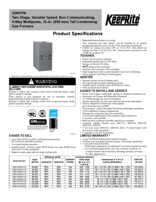
Product SpecificationsA200417Illustrations and photographs are only representative. Some product models may vary.A200326EASIER TO SELL•Up to 96% AFUE in upflow and horizontal positions 95% AFUE in downflow position •Two-stage heating operation•Variable-speed, constant torque ECM blower for extra SEER boost with select cooling equipment•Supports single-stage and two-stage cooling units•Dehumidification feature in cooling•NOx emissions less than 40ng/J; can be installed in air quality management districts with a 40 ng/J NOx emissions requirement.•Cabinet air leakage less than 2.0% at 1.0 in. W.C. and cabinet air leakage less than 1.4% at 0.5 in. W.C. when tested in accordance with ASHRAE standard 193TOUGHER•Flame roll-out sensors standard•Adjustable heating blower OFF delay •Factory set blower ON delay •RPJ ® primary heat exchanger•Stainless steel secondary heat exchanger•High temperature limit control designed to prevent overheating •Direct ignition with Silicon Nitride ignitor QUIETER•Operates quieter at lower heating rates•Two-speed induced draft combustion blower•Variable speed, constant torque ECM blower motor •Fully insulated steel cabinetEASIER TO INSTALL AND SERVICE•Direct vent (2-pipe), single-pipe venting or ventilated combustion air •Electronic Air Cleaner and Humidifier terminals •35” (889mm) high, for ease of installation•Quarter turn knobs for easy door removal and secure attachment •Factory shipped for natural gas, with propane gas conversion kits available•Four position - upflow/downflow/horizontal (left/right) installation •Twelve different venting configurations•Through the casing flue pipe for counterflowor horizontal applications with accessory (order separately)•Concentric vent available•Slide out heat exchanger assembly and blower assembly•Twinning capable (model sizes 0601714, 0801716, 0802120,1002120, 1202422)•5 ton sizes (sizes 0802120, 1002120) allow 15 Amp breaker with acccessory (order separately)•Compatible with 24V thermostatsLIMITED WARRANTY *•5 year No Hassle Replacementt limited warranty•Lifetime heat exchanger limited warranty with timely registration •5 year parts limited warranty- With timely registration, an additional 5 year parts limited warranty * For residential applications only. See warranty certificate for complete details and restrictions, including warranty coverage for other applications.G96VTNTwo-Stage, Variable Speed, Non-Communicating, 4-Way Multipoise, 35-in. (889 mm) Tall Condensing Gas Furnace!CARBON MONOXIDE POISONING AND FIRE HAZARDFailure to follow this warning could result in personal injury, death,and/or property damage.This furnace is not designed for use in recreation vehicles,manufactured (mobile) homes or outdoors.Failure to follow this warning could result in personal injury, death,and/or property damage.Use of the AHRI Certified TM Mark indicates a manufacturer's participation in the program. For verification of certification for individual products,go to .Model Number Input (BTUH)Efficiency AFUEENERGY STAR®Cooling Capacity CFM range @ .5 in. w.c.(125 Pa)Dimensions H x W x D Inches (Millimeters)SHIP WT.LB (KG) Upflow/Hz Downflow G96VTN040141040,00096%95%Yes 445 - 103035 x 14-3/16 x 29-1/2 (889 x 361 x 750)123 (55.8)G96VTN040171240,00096%95%Yes 400 - 110535 x 17-1/2 x 29-1/2 (889 x 445 x 750)133 (60.3)G96VTN060141260,00095%95%Yes 445 - 111535 x 14-3/16 x 29-1/2 (889 x 361 x 750)132 (59.9)G96VTN060171460,00096%95%Yes 210 - 147535 x 17-1/2 x 29-1/2 (889 x 445 x 750)139 (63.0)G96VTN080171680,00096%95%Yes 360 - 165535 x 17-1/2 x 29-1/2 (889 x 445 x 750)147 (66.7)G96VTN080212080,00096%95%Yes 440 - 200535 x 21 x 29-1/2 (889 x 533 x 750)156 (70.7)G96VTN1002120100,00096%95%Yes 405 - 200535 x 21 x 29-1/2 (889 x 533 x 750)170 (77.1)G96VTN1002122100,00096%95%Yes 975 - 227535 x 21 x 29-1/2 (889 x 533 x 750)171 (77.6)G96VTN1202422120,00096%95%Yes505 - 219035 x 24-1/2 x 29-1/2 (889 x 622 x 750)190 (86.2)DIMENSIONAL DRAWINGA200327FURNACE SIZEABCDSHIP WT .LB (KG) CABINET WIDTH OUTLET WIDTH BOTTOM INLET WIDTHAIR INTAKE G96VTN040141014-3/16 (361)12-1/2 (319)12-9/16 (322)7-1/8 (181)123 (55.8)G96VTN040171217-1/2 (445)15-7/8 (403)16 (406)8-3/4 (222)133 (60.3)G96VTN060141214-3/16 (361)12-1/2 (319)12-9/16 (322)7-1/8 (181)132 (59.9)G96VTN060171417-1/2 (445)15-7/8 (403)16 (406)8-3/4 (222)139 (63.0)G96VTN080171617-1/2 (445)15-7/8 (403)16 (406)8-3/4 (222)147 (66.7)G96VTN080212021 (533)19-3/8 (492)19-1/2 (495)10-1/2 (267)156 (70.7)G96VTN100212021 (533)19-3/8 (492)19-1/2 (495)10-1/2 (267)170 (77.1)G96VTN100212221 (533)19-3/8 (492)19-1/2 (495)10-1/2 (267)171 (77.6)G96VTN120242224-1/2 (622)22-7/8 (581)23 (584)12-1/4 (311)190 (86.2)U.S . E C C N : N o t S u b j e c t t o R e g u l a t i o n (N .S .R .)N O T E : A L L D I M E N S I O N S I N I N C H (M M )MODEL NUMBER NOMENCLATUREA190043FURNACE COMPONENTSA190145MINIMUM CLEARANCES TO COMBUSTIBLE MATERIALS FOR ALL UNITSDIGIT POSITION 12,34567-910,1112,131415||||||||||BRAND A, B, C…1, 2, 3…EFFICIENCY08 = 800 CFM 10 = 1000 CFM 12 = 1200 CFM 14 = 1400 CFM 16 = 1600 CFM 20 = 2000 CFM 22 = 2200 CFMMAJOR SERIESMINOR SERIES026 = 26,000 BTU/h 040 = 40,000 BTU/h 045 = 45,000 BTU/h …….155 = 155,000 BTU/h14 = 14.2”17 = 17.5”21 = 21.0”24 = 24.5”FEATUREHEATING INPUTCABINET WIDTHCOOLING CAPACITYF, G, N, R C = Constant Airflow Variable-Speed ECME =Fixed-Speeds, Constant Torque (FCT) ECM P = PSCV = Variable Speed , Constant Torque (VCT)80 - 80% AFUE 92 - 92% AFUE 95 - 95% AFUE 96 - 96% AFUE 97 - 97% AFUEM - ModulatingS - Single Stage T - Two StageL = Low NOxM = Mobile/Manufactured Home N = Standard NOx U = Ultra Low NOxMOTOR TYPEHEATING STAGESECMINSIDE DOOR FIGURE).BOARDHOT SURFACE POSITION CLEARANCE in.(mm)REAR0FRONT (Combustion air openings in furnace and in structure)1 (25)Required for service *24 (610)All Sides of Supply Plenum *1 (25)Sides 0Vent0Top of Furnace1 (25)*.Consult your local building codesPHYSICAL DATAHeating Capacity and Efficiency040141004017120601412060171408017160802120100212010021221202422Input HighHeat(BTUH)40,00040,00060,00060,00080,00080,000100,000100,000120,000Low Heat (BTUH)26,00026,00039,00039,00052,00052,00065,00065,00078,000Output HighHeat(BTUH)39,00039,00058,00058,00078,00078,00097,00097,000117,000Low Heat (BTUH)25,00025,00038,00038,00050,00051,00063,00063,00076,000Certified TemperatureRise Range ºF (ºC)High Heat 40 - 70(22 - 39)40 - 70(22 - 39)40 - 70(22 - 39)40 - 70(22 - 39)40 - 70(22 - 39)40 - 70(22 - 39)40 - 70(22 - 39)40 - 70(22 - 39)40 - 70(22 - 39)Low Heat30 - 60(17 - 33)30 - 60(17 - 33)30 - 60(17 - 33)30 - 60(17 - 33)30 - 60(17 - 33)30 - 60(17 - 33)30 - 60(17 - 33)30 - 60(17 - 33)30 - 60(17 - 33)Airflow Capacity and Blower Data Rated External Static Pressure (in. w.c.)Heating 0.100.100.120.120.150.150.200.200.20Cooling0.500.500.500.500.500.500.500.500.50Airflow Delivery@ Rated ESP (CFM)High Heat8008501110113514501555186517652120Low Heat56062577086011301200143513501625Cooling103011051115147516552005200522752190Cooling Capacity (tons)@ 400, 350 CFM/ton 400 CFM/ton 2 2.5 2.5 3.5455 5.55350 CFM/ton 2.5334 4.5 5.55.566Direct-Drive Motor Type Electronically Commutated Motor (ECM)Direct-Drive Motor HP1/21/21/23/43/41111Motor Full Load Amps Default / LowAmp Kit **.Low Amp Kit (NAHA00101PC) allows select furnaces to be installed with a 15 Amp Breaker and 14 AWG wire within the listed wire length. Affected data shown as DefaultValue/Value with Lower Amp Kit.6.36.5 6.310.19.213.9/10.413.9/10.410.411.7RPM Range 600 - 2000400 - 1200600 - 2000400 - 1200400 - 1200400 - 1200400 - 1200400 - 1300400 - 1200Speed Selections Variable (PWM)Blower Wheel Dia xWidthin.11 x 711 x 811 x 711 x 811 x 811 x 1011 x 1011 x 1011 x 11Air Filtration SystemField Supplied FilterFilter Used for Certified Watt Data 325531-40*Electrical Data InputVoltageVolts-Hertz-Phase115-60-1Operating VoltageRangeMin-Max104-127Maximum Input AmpsDefault / Low Amp Kit{Amps 7.07.27.110.910.014.7/11.314.7/11.312.612.6Unit Ampacity Default /Low Amp Kit{Amps 9.79.89.714.613.419.3/14.919.4/15.016.716.7Minimum Wire SizeDefault / Low Amp Kit{AWG 141414141412/1412/141212Maximum Wire Length @ Minimum Wire SizeDefault / Low Amp Kit{Feet 383738252729/2429/243434(M) (11.7)(11.5)(11.7)(7.7)(8.4)(9.0/7.5)(9.0/7.5)(10.5)(10.5)Maximum Fuse/Ckt Bkr (Time-Delay TypeRecommended)Default / Low Amp Kit{Amps 151515151520/1520/152020Transformer Capacity (24vac output)VA External Control Power Available Heating 24.3 VA Cooling 34.6 VAControlsGas Connection Size 1/2” - NPTBurners (Monoport)223344556Gas Valve (Redundant)Manufacturer White RodgersMinimum Inlet Gas pressure (in. wc) 4.50Maximum Inlet Gas pressure (in. wc)13.60Manufactured (Mobile) Home Kit not approved for MH useIgnition DeviceSilicon NitrideHeating Blower Control (Heating Off-Delay)Adjustable: 90, 120, 150, 180 secondsCooling Blower Control (Time Delay Relay)90 secondsCommunication System NoneThermostat Connections R, W/W1, W2 Y/Y2, Y1, G, Com 24V, DHUM Accessory ConnectionsEAC (115vac); HUM (24vac); 1-stg. AC (via Y/Y2)AIR DELIVERYAir Delivery - CFM (With Filter)(SW1-5 and SW2-2 set to OFF, except as indicated. See notes 1 and 2.)Unit Size:0401410A Clg/CF Switch settings External Static Pressure (ESP)Clg Switches:SW2-8SW2-7SW2-60.10.20.30.40.50.60.70.80.9 1.0 Clg Default:OFF OFF OFF112511051080105510301005975955930905Cooling (SW2-8,7,6)OFF OFF ON605565525485445See Note 4OFF ON OFF760730695655625590555525490455 OFF ON ON950925900870840810785760730705 ON OFF OFF112511051080105510301005975955930905 ON OFF ON113011051080105510301005980955930905 ON ON OFF113011051080105510301005980955930905 ON ON ON113011051080105510301005980955930905 Maximum Clg Airflow2113011051080105510301005980955930905CF Switches SW2-5SW2-4SW2-3Low-Clg Default:OFF OFF OFF605565525485445See Note 4Low-Cooling (SW2-5,4,3)OFF OFF ON605565525485445See Note 4OFF ON OFF760730695655625590555525490455 OFF ON ON950925900870840810785760730705 ON OFF OFF112511051080105510301005975955930905 ON OFF ON113011051080105510301005980955930905 ON ON OFF113011051080105510301005980955930905 ON ON ON113011051080105510301005980955930905Cont. Fan Default:OFF OFF OFF385335See Note 4Continuous Fan (SW2-5,4,3)OFF OFF ON245180See Note 4 OFF ON OFF310245See Note 4 OFF ON ON385335See Note 4 ON OFF OFF385335See Note 4 ON OFF ON385335See Note 4 ON ON OFF385335See Note 4 ON ON ON385335See Note 4Heating (SW1)High Heat Airflow3800770730700665635605570540510 Low Heat Airflow3560520470425390See Note 4Unit Size:0401712A Clg/CF Switch settings External Static Pressure (ESP)Clg Switches:SW2-8SW2-7SW2-60.10.20.30.40.50.60.70.80.9 1.0 Clg Default:OFF OFF OFF1240121011801145110510601005950895835Cooling (SW2-8,7,6)OFF OFF ON585540490445400360315265210155 OFF ON OFF780740695655620580545510480445 OFF ON ON975945910870835805775740710680 ON OFF OFF117011401115108510501020985945890835 ON OFF ON1240121011801145110510601005950895835 ON ON OFF1240121011801145110510601005950895835 ON ON ON1240121011801145110510601005950895835 Maximum Clg Airflow21240121011801145110510601005950895835CF Switches SW2-5SW2-4SW2-3Low-Clg Default:OFF OFF OFF585540490445400See Note 4Low-Cooling (SW2-5,4,3)OFF OFF ON585540490445400See Note 4OFF ON OFF780740695655620580545510480445 OFF ON ON975945910870835805775740710680 ON OFF OFF117011401115108510501020985945890835 ON OFF ON1240121011801145110510601005950895835 ON ON OFF1240121011801145110510601005950895835 ON ON ON1240121011801145110510601005950895835Cont. Fan Default:OFF OFF OFF585540490445400See Note 4Continuous Fan (SW2-5,4,3)OFF OFF ON305235See Note 4OFF ON OFF470410350See Note 4OFF ON ON585540490445400See Note 4 ON OFF OFF585540490445400See Note 4 ON OFF ON585540490445400See Note 4 ON ON OFF585540490445400See Note 4 ON ON ON585540490445400See Note 4Heating (SW1)High Heat Airflow3850810770730700660630595560530 Low Heat Airflow3625580535490445405365320270220Clg Switches:SW2-8SW2-7SW2-60.10.20.30.40.50.60.70.80.9 1.0 Clg Default:OFF OFF OFF1180115011301100107510451020995965935Cooling (SW2-8,7,6)OFF OFF ON625585540495445See Note 4OFF ON OFF820785745710670635595560525490 OFF ON ON1000970935905875845815785755725 ON OFF OFF1180115011301100107510451020995965935 ON OFF ON122011951170114011151090106510351010985 ON ON OFF122011951170114011151090106510351010985 ON ON ON122011951170114011151090106510351010985 Maximum Clg Airflow2122011951170114011151090106510351010985CF Switches SW2-5SW2-4SW2-3Low-Clg Default:OFF OFF OFF625585540495445See Note 4Low-Cooling (SW2-5,4,3)OFF OFF ON625585540495445See Note 4OFF ON OFF820785745710670635595560525490 OFF ON ON1000970935905875845815785755725 ON OFF OFF1180115011301100107510451020995965935 ON OFF ON122011951170114011151090106510351010985 ON ON OFF122011951170114011151090106510351010985 ON ON ON122011951170114011151090106510351010985Cont. Fan Default:OFF OFF OFF375315See Note 4Continuous Fan (SW2-5,4,3)OFF OFF ON200125See Note 4 OFF ON OFF285215See Note 4 OFF ON ON375315See Note 4 ON OFF OFF375315See Note 4 ON OFF ON375315See Note 4 ON ON OFF375315See Note 4 ON ON ON375315See Note 4Heating (SW1)High Heat Airflow311151090106010351010980955930905875 Low Heat Airflow3780740695655615575530490450405Unit Size:0601714A Clg/CF Switch settings External Static Pressure (ESP)Clg Switches:SW2-8SW2-7SW2-60.10.20.30.40.50.60.70.80.9 1.0 Clg Default:OFF OFF OFF1330129512601220119011501110107510451005Cooling (SW2-8,7,6)OFF OFF ON725600435280210See Note 4OFF ON OFF780725660615540See Note 4OFF ON ON975925875835785750690655610570 ON OFF OFF11601120109010451010970920885840800 ON OFF ON1330129512601220119011501110107510451005 ON ON OFF1705165015951545147514151340127512001105 ON ON ON1705165015951545147514151340127512001105 Maximum Clg Airflow21705165015951545147514151340127512001105CF Switches SW2-5SW2-4SW2-3Low-Clg Default:OFF OFF OFF725600435280210See Note 4Low-Cooling (SW2-5,4,3)OFF OFF ON725600435280210See Note 4OFF ON OFF780725660615540See Note 4OFF ON ON975925875835785750690655610570 ON OFF OFF11601120109010451010970920885840800 ON OFF ON1330129512601220119011501110107510451005 ON ON OFF1705165015951545147514151340127512001105 ON ON ON1705165015951545147514151340127512001105Cont. Fan Default:OFF OFF OFF725600435280210See Note 4Continuous Fan (SW2-5,4,3)OFF OFF ON725600435280210See Note 4OFF ON OFF780725660615540See Note 4OFF ON ON975925875835785750690655610570 ON OFF OFF975925875835785750690655610570 ON OFF ON975925875835785750690655610570 ON ON OFF975925875835785750690655610570 ON ON ON975925875835785750690655610570Heating (SW1)High Heat Airflow31145110510751030995955905870825785 Low Heat Airflow3870820760720655620560525470435Clg Switches:SW2-8SW2-7SW2-60.10.20.30.40.50.60.70.80.9 1.0 Clg Default:OFF OFF OFF1595156015301500147014401405137013401290Cooling (SW2-8,7,6)OFF OFF ON625555495425360300See Note 4OFF ON OFF810755700645595540480425380330 OFF ON ON1040995950900860815770725680630 ON OFF OFF121511751135109510551015975935900860 ON OFF ON1390135513201285124512101175114011051070 ON ON OFF1595156015301500147014401405137013401290 ON ON ON1790176017351700165516101570148513951295 Maximum Clg Airflow21790176017351700165516101570148513951295CF Switches SW2-5SW2-4SW2-3Low-Clg Default:OFF OFF OFF625555495425360300See Note 4Low-Cooling (SW2-5,4,3)OFF OFF ON625555495425360300See Note 4OFF ON OFF810755700645595540480425380330 OFF ON ON1040995950900860815770725680630 ON OFF OFF121511751135109510551015975935900860 ON OFF ON1390135513201285124512101175114011051070 ON ON OFF1595156015301500147014401405137013401290 ON ON ON1790176017351700165516101570148513951295Cont. Fan Default:OFF OFF OFF625555495425360300See Note 4Continuous Fan (SW2-5,4,3)OFF OFF ON465390300See Note 4OFF ON OFF625555495425360300See Note 4 OFF ON ON690630570510445385See Note 4 ON OFF OFF690630570510445385See Note 4 ON OFF ON690630570510445385See Note 4 ON ON OFF690630570510445385See Note 4 ON ON ON690630570510445385See Note 4Heating (SW1)High Heat Airflow31470143514001365133012951260122511901155 Low Heat Airflow31150111010701030990950910870830790Unit Size:0802120A Clg/CF Switch settings External Static Pressure (ESP)Clg Switches:SW2-8SW2-7SW2-60.10.20.30.40.50.60.70.80.9 1.0 Clg Default:OFF OFF OFF1905187018251785175017001665162515601460Cooling (SW2-8,7,6)OFF OFF ON950770620515440365See Note 4OFF ON OFF1015935880825765690625580See Note 4 OFF ON ON115511051040990920875815755710645 ON OFF OFF1335129012451190114510851040990930890 ON OFF ON1520148514351390134013001255120011601115 ON ON OFF1905187018251785175017001665162515601460 ON ON ON2290223021602085200519151820173016401525 Maximum Clg Airflow22290223021602085200519151820173016401525CF Switches SW2-5SW2-4SW2-3Low-Clg Default:OFF OFF OFF950770620515440365See Note 4Low-Cooling (SW2-5,4,3)OFF OFF ON645540435See Note 4OFF ON OFF950770620515440365See Note 4OFF ON ON1015935880825765690625580See Note 4 ON OFF OFF115511051040990920875815755710645 ON OFF ON1335129012451190114510851040990930890 ON ON OFF1520148514351390134013001255120011601115 ON ON ON1905187018251785175017001665162515601460Cont. Fan Default:OFF OFF OFF950770620515440365See Note 4Continuous Fan (SW2-5,4,3)OFF OFF ON645540435See Note 4OFF ON OFF950770620515440365See Note 4OFF ON ON1015935880825765690625580See Note 4 ON OFF OFF115511051040990920875815755710645 ON OFF ON1335129012451190114510851040990930890 ON ON OFF1520148514351390134013001255120011601115 ON ON ON1520148514351390134013001255120011601115Heating (SW1)High Heat Airflow31575153514851445140013501310126012151170 Low Heat Airflow312301170112510651015955900855795755Clg Switches:SW2-8SW2-7SW2-60.10.20.30.40.50.60.70.80.9 1.0 Clg Default:OFF OFF OFF1890184518001755170016551610156015101460Cooling (SW2-8,7,6)OFF OFF ON1015825630485405325See Note 4OFF ON OFF1080895815740690615555475See Note 4 OFF ON ON115510801020940890825785710660590 ON OFF OFF131012601195114010751025970925875810 ON OFF ON1520147514251365131512551210115511101055 ON ON OFF1890184518001755170016551610156015101460 ON ON ON2290223021602085200519151820173016401525 Maximum Clg Airflow22290223021602085200519151820173016401525CF Switches SW2-5SW2-4SW2-3Low-Clg Default:OFF OFF OFF1015825630485405325See Note 4Low-Cooling (SW2-5,4,3)OFF OFF ON745640535See Note 4OFF ON OFF1015825630485405325See Note 4OFF ON ON1080895815740690615555475See Note 4 ON OFF OFF115510801020940890825785710660590 ON OFF ON131012601195114010751025970925875810 ON ON OFF1520147514251365131512551210115511101055 ON ON ON1890184518001755170016551610156015101460Cont. Fan Default:OFF OFF OFF1015825630485405325See Note 4Continuous Fan (SW2-5,4,3)OFF OFF ON745640535See Note 4OFF ON OFF1015825630485405325See Note 4OFF ON ON1080895815740690615555475See Note 4 ON OFF OFF115510801020940890825785710660590 ON OFF ON115510801020940890825785710660590 ON ON OFF115510801020940890825785710660590 ON ON ON115510801020940890825785710660590Heating (SW1)High Heat Airflow31905186518251775173016851640159015451490 Low Heat Airflow31480143513751330126512151160111510601005Unit Size:1002122A Clg/CF Switch settings External Static Pressure (ESP)Clg Switches:SW2-8SW2-7SW2-60.10.20.30.40.50.60.70.80.9 1.0 Clg Default:OFF OFF OFF1990194519051865182017801735169516501600Cooling (SW2-8,7,6)OFF OFF ON885800700See Note 4OFF ON OFF11051035955870See Note 4OFF ON ON1255119011251055975See Note 4ON OFF OFF1445139013301270121011401075See Note 4ON OFF ON16551610156015051455140013451285See Note 4 ON ON OFF1990194519051865182017801735169516501600 ON ON ON2135209520602025198519451905186518201780 Maximum Clg Airflow22440240523652320227522302180213520802030CF Switches SW2-5SW2-4SW2-3Low-Clg Default:OFF OFF OFF885800700See Note 4Low-Cooling (SW2-5,4,3)OFF OFF ON740630See Note 4OFF ON OFF885800700See Note 4OFF ON ON11051035955870See Note 4ON OFF OFF1255119011251055975See Note 4ON OFF ON1445139013301270121011401075See Note 4ON ON OFF16551610156015051455140013451285See Note 4 ON ON ON1990194519051865182017801735169516501600Cont. Fan Default:OFF OFF OFF885800700See Note 4Continuous Fan (SW2-5,4,3)OFF OFF ON740630See Note 4OFF ON OFF885800700See Note 4OFF ON ON11051035955870See Note 4ON OFF OFF1255119011251055975See Note 4ON OFF ON1445139013301270121011401075See Note 4ON ON OFF16551610156015051455140013451285See Note 4 ON ON ON16551610156015051455140013451285See Note 4Heating (SW1)High Heat Airflow31810176517201675162515751525147514251375 Low Heat Airflow3140513501290122511601100See Note 4NOTES for Cooling and Heating Air Delivery - CFM (Bottom Return with Filter)1.Nominal 350 CFM/ton cooling airflow is delivered with SW1-5 and SW2-2 set to OFF. Set both SW1-5 and SW2-2 to ON for +7% airflow (nominal 370 CFM/ton)Set SW1-5 to ON and SW2-2 to OFF for +15% airflow (nominal 400 CFM/ton)Set SW1-5 to OFF and SW2-2 to ON for -7% airflow (nominal 325 CFM/ton)The above adjustments in airflow are subject to motor horsepower range/capacityThis applies to Cooling and Low-Cooling airflow, but does not affect continuous fan airflow.2.Maximum cooling airflow is achieved when switches SW2-6, SW2-7, SW2-8 and SW1-5 are set to ON, and SW2-2 is set to OFF.3.All heating CFM’s are when comfort/efficiency adjustment switch SW1-4 is set to OFF.4.Ductwork must be sized for high-heating CFM within the operational range of ESP. Operation within the blank areas of the chart is not recommended because high-heat operation will be above 1.0 ESP.5.All airflows on 21” (533 mm) casing size furnaces are 5% less on side-return only installations.6.Side returns for 24.5” (622 mm) casing sizes require two sides, or a side and bottom to allow sufficient airflow at the return of the furnace.7.Airflows over 1800 CFM require bottom return, two-side return, or bottom and side return or excessive watt draw may result. A minimum filter size of 20x25” (508 x 635 mm) is required.FURNACE SETUP SWITCH DESCRIPTIONA190148A190048Clg Switches:SW2-8SW2-7SW2-60.10.20.30.40.50.60.70.80.9 1.0Clg Default:OFF OFF OFF 2060201519751930188518401790175017051630Cooling (SW2-8,7,6)OFF OFF ON 865775690595505425See Note 4OFF ON OFF 10801005935860785705625555490425OFF ON ON 12851220115010851020960895820750690ON OFF OFF 146514101350128512301175111510601000935ON OFF ON 1685163515851530147514201375132512701225ON ON OFF 2060201519751930188518401790175017051630ONONON2265222521802145210020602010189517701645Maximum Clg Airflow 22320231022702230219021352020189517701645CF Switches SW2-5SW2-4SW2-3Low-Clg Default:OFF OFF OFF 865775690595505425See Note 4Low-Cooling (SW2-5,4,3)OFF OFF ON 585470See Note 4OFF ON OFF 865775690595505425See Note 4OFF ON ON 10801005935860785705625555490425ON OFF OFF 12851220115010851020960895820750690ON OFF ON 146514101350128512301175111510601000935ON ON OFF 1685163515851530147514201375132512701225ON ON ON 2060201519751930188518401790175017051630Cont. Fan Default:OFF OFF OFF 865775690595505425See Note 4Continuous Fan (SW2-5,4,3)OFF OFF ON 585470See Note 4OFF ON OFF 730630See Note 4OFF ON ON 865775690595505425See Note 4ON OFF OFF 865775690595505425See Note 4ON OFF ON 865775690595505425See Note 4ON ON OFF 865775690595505425See Note 4ONON ON865775690595505425See Note 4Heating (SW1)High Heat Airflow 32165212020752030198519401895185017701645Low Heat Airflow316751625157515251475142513751325127512251. Default A/C airflow when A/C setup switches are in OFF position.2. Default Low-Stage A/C airflow when CF switchesACCESSORIESPART NUMBER COMPONENT NAME DESCRIPTION 0401410060171406014120601714NAHB001101CT EXTERNAL TRAP KIT CONDENSATE TRAP XXXXNAHA00110DA DRAIN ACCESSORY 1/2” CPVC TO 3/4” PVC(10 PACK)X X X X NAHA002CV VENT TERMINATION KIT 2” CONCENTRIC VENT X X X X NAHA001CV 3” CONCENTRIC VENT X -X NAHA00101VC INTERNAL VENT KIT THROUGH THE CABINETX X X X NAHA00301VT DIRECT VENT TERMINATION KIT 2” BRACKET X X X X NAHA00401VT 3” BRACKET -X -X NAHA00101CK INLET AIR PIPE COUPLINGCOUPLING FORPOLYPROPYLENE VENTSYSTEMSX X X X NAHA00101HV HORIZONTAL INSTALLATION KIT TRAP GROMMET (DIRECT VENT APPLICATION ONLY)X X X X NAHA00101HH FREEZE PROTECT KIT CONDENSATE DRAIN LINE -TAPEX X X X NAHA00201HH CONDENSATE FREEZEPROTECT KIT CONDENSATE TRAP WITHHEAT PADX X X X NAHA01101SB FLOOR BASE KIT COMBUSTIBLE FLOOR X X X X AGAGC9NPS01B **.Factory authorized and field installed. Gas conversion kits are CSA recognized.GAS CONVERSION KIT NATURAL TO PROPANE X X X X AGAGC9PNS01B *PROPANE TO NATURAL X X X X 1188594††.Order through FAST Parts.X = Accessory availableGAS VALVE TOWER PORTADAPTER KITADAPTER FOR GAS VALVE X X X X 325531-402†WASHABLE FILTER 3/4” X 16” X 25” WASHABLEFILTER X X X X FHG1425-2†EXTERNAL BOTTOM FILTERRACK14”-1/2 X 25” WASHABLE FILTER INCLUDED X -X -FHG1625-2†16” X 25” WASHABLE FILTERINCLUDED -X -X NAHB00101CA COIL ADAPTER KITWITH NO OFFSET X X X X NAHB00201CA WITH SINGLE OFFSET X X X X NAHB00301CA WITH DOUBLE OFFSETX X X X NAHA01401RA RETURN AIR KIT 14-3/16” WIDE X -X -NAHA01701RA 17-1/2” WIDE -X -X NAHA001NK CONDENSATE NEUTRALIZER KIT NEUTRALIZES CONDENSATE X X X X AGATWNPME01BTWINNING KITTWO FURNACES OF SAMEMODEL & SERIES---XACCESSORIES (continued)ORIFICESPART NUMBER COMPONENT NAME DESCRIPTION 08017160802120100212010021221202422NAHB001101CT EXTERNAL TRAP KIT CONDENSATE TRAP XXXXXNAHA00110DA DRAIN ACCESSORY 1/2” CPVC to 3/4” PVC(10 PACK)X X X X X NAHA002CV VENT TERMINATION KIT 2” CONCENTRIC VENT X X X X -NAHA001CV 3” CONCENTRIC VENT X X X X X NAHA00101VC INTERNAL VENT KITTHROUGH THE CABINETX X X X X NAHA00301VT DIRECT VENT TERMINATION KIT 2” BRACKET X X X X -NAHA00401VT 3” BRACKET X X X X X NAHA00101CK INLET AIR PIPE COUPLING COUPLING FORPOLYPROPYLENE VENTSYSTEMSX X X X X NAHA00101HV HORIZONTAL INSTALLATIONKIT TRAP GROMMET (direct Ventapplication only)X X X X X NAHA00101HH FREEZE PROTECT KIT CONDENSATE DRAIN LINE -TapeX X X X X NAHA00201HH CONDENSATE FREEZEPROTECT KIT CONDENSATE TRAP WITHHEAT PADX X X X X NAHA01101SB FLOOR BASE KIT COMBUSTIBLE FLOOR X X X X X AGAGC9NPS01B**.Factory authorized and field installed. Gas conversion kits are CSA recognized.GAS CONVERSION KIT NATURAL TO PROPANE X X X X X AGAGC9PNS01B *PROPANE TO NATURAL X X X X X 1188594††.Order through FAST Parts.X = Accessory availableGAS VALVE TOWER PORTADAPTER KITADAPTER FOR GAS VALVE X X X X X 325531-402†WASHABLE FILTER3/4” X 16” x 25” WASHABLEFILTERX ----325531-403†3/4” X 20 X 25” WASHABLEFILTER INCLUDED-X X X -325531-404†3/4” X 24 X 25” WASHABLEFILTER INCLUDED --X -X FHG1625-2†EXTERNAL BOTTOM FILTERRACK17-1/2” X 25” WASHABLE FILTER INCLUDEDX ----FHG2025-2†21” X 25” WASHABLE FILTERINCLUDED-X X X -FHG2424-2†24-1/2” X 25” WASHABLE FILTER INCLUDED ----X NAHB00101CA COIL ADAPTER KIT WITH NO OFFSET X X X X X NAHB00201CA WITH SINGLE OFFSET X X X X X NAHB00301CA WITH DOUBLE OFFSETX X X X X NAHA01701RA RETURN AIR KIT 17-1/2” wide X ----NAHA02101RA 21” wide -X X X -NAHA02401RA 24-1/2” wide----X AGATWNPME01A TWINNING KITTWO FURNACES OF SAMEMODEL & SERIESX X X -X NAHA001NK CONDENSATE NEUTRALIZERKITNEUTRALIZES CONDENSATEX X X X X NAHA00101PCLOWER AMP KIT ALLOWS 15 AMP BREAKER-XX--DESCRIPTIONGas Orifice Kit - #42 (Nat Gas)1185612See Installation Instructions for model, altitude, and heat value usages.Gas Orifice Kit - #43 (Nat Gas)1176928Gas Orifice Kit - #44 (Nat Gas)1185574Gas Orifice Kit - #45 (Nat Gas)1177213Gas Orifice Kit - #46 (Nat Gas)1183809Gas Orifice Kit - #47 (Nat Gas)1185613Gas Orifice Kit - #48 (Nat Gas)1185614Gas Orifice Kit - 1.25mm (LP)1185617。
E3643A中文资料(Agilent(Hewlett-Packard))中文数据手册「EasyDatasheet - 矽搜」

E3600A-100测试线套件
机架安装套件*
安捷伦E3640A / 41A / 42A / 43A / 44A / 45A
要上架安装两台仪器并排侧
锁连杆套件(P / N 5061-9694) 法兰套件(P / N 5063-9212)
为机架安装在一个或两个仪器 滑动支承架
支撑架(P / N 5063-9255) 滑道套件(P / N 1494-0015)要求
可编程直流电源 在一个伟大提供极大性能
价格.所有十款提供清洁 动力,优良调节,快 瞬态响应和内置GPIB 和RS-232接口.他们是
设计满足研发需求
设计验证,生产测试, QA验证,以及其他高要求
与安捷伦应用
技术质量和可靠性.
稳定输出
用0.01%负载和线路调整,安捷 伦E364xA电源能够防护持稳定输 出 ,当电源线和负载发生变化.他们
OVP 准确性, ±(%输出+偏移)
激活时间
¥3 V/ 10毫秒,OVP 3伏
精度指标经过1小时热身空载和标定在25ºC有效. 仪表精度指标是最低10 mV十进制受限于前面板分辨率. 所需要输出电压最大时间以改变从1%至99%,或反之亦然在收到电压或经由直接apply命令 GPIB或RS-232接口. 平均时间输出启动和下降发生OVP条件后.
查看两个电压或电流同时显示
.
通用动力
E364xA电源给
输出范围.输出负载是 防止过压,这
可以很容易地监控和调整 从前面面板和遥控
接口.遥感可用
在后方终端消除错误 引起电压降负载
线索.这些电源提供新
前面多功能接线柱 在面板和螺栓连 引线以及常规香蕉
剪辑和裸线.可选 机架安装套件.安捷伦 E364xA系列采用散热风扇具有自 动调速,以减少噪音.
ANDF-2型蓄电池放电仪说明书资料

ANDF-220V/200A型蓄电池智能放电装置ANDF-220V/200A型蓄电池智能放电装置使用说明书河南省安耐德电力设备有限公司目录LIST第一章概述Chapter I General1.1 概述General1.2 产品特点Characteristics1.3 技术指标Technical indexes第二章用户操作界面Chapter II User’s operation interface2.1使用建议Application recommendation2.2接线Wiring2.3基本操作方法Basic operation method2.3.1 基本特点Basic features2.3.2 用户操作键盘User’s operation keyboard2.3.3 基本操作方法Basic operation method第三章接口定义及注意事项Chapter III Definitions of interface & Notes3.1智能放电装置接口Interface of intelligent discharge devic3.2 注意事项NotesJZ-BID-Ⅱ型蓄电池智能放电装置使用说明书手册导读Guidelines to the Instruction本手册的定位Positioning详细介绍了ANDF-220V/120A型蓄电池智能放电装置的基本原理功能性能和特点结构与接口并给出了相关的图表This Instruction detailed the basic principle, functions, performance,characteristics, structure and interface as to the JB-BID-II accumulatorintelligent discharge device, including relevant figures.本手册的主要用途Main use of the Instruction1. 产品技术推广和制作标书技术条款Technical promotion of products, used as technical terms for tender2. 用户操作过程的参考Reference in terms of operation3. 指导工程设计单位完成电力机房电源工程设计Guidance for engineering design unit to complete the powerengineering design for power room4. 用户的参考资料Referential material for users读者Readers 工程设计选型人员Type selection staff for engineering电力操作电源用户User for power operation技术推广和投标人员Technical promoter and tender staff第一章概述Chapter I General1.1 概述General蓄电池作为备用电源在直流系统中起着极其重要的作用,从而在电力、通信、金融、交通等各行各业中得到广泛的应用。
- 1、下载文档前请自行甄别文档内容的完整性,平台不提供额外的编辑、内容补充、找答案等附加服务。
- 2、"仅部分预览"的文档,不可在线预览部分如存在完整性等问题,可反馈申请退款(可完整预览的文档不适用该条件!)。
- 3、如文档侵犯您的权益,请联系客服反馈,我们会尽快为您处理(人工客服工作时间:9:00-18:30)。
typ.
1900
5990
波长
nm λP
627
(磷
UR
砷化镓
/
GAP)Unit
VF
1.9
V
VF
2.5
V
IR
10
uA
λP
627
nm
λD
625
nm
Δλ
45
nm
C
15
pF
描写
共阳极. RT.手十进制
芯片中文手册,看全文,戳
UR
备注:
如有特殊排序是必需的(例如,基于正向电压,发光强度/光通量或波长分档),
分类处理的典型精度如下:
1.波长:+/- 1纳米 2.发光强度/光通量:+/- 15% 3.正向电压:+/- 0.1V 注意:精度可取决于排序参数.
芯片中文手册,看全文,戳
推荐焊接模式(单位: mm;公差:
± 0.15)
磁带规格(单位: mm)
芯片中文手册,看全文,戳
注:1. 所有尺寸为毫米(英寸). 2.公差为±0.25(0.01“),除非另有说明. 3.反射器和电路板之间的间隙应不超过0.25毫米. 4.Specifications如有更改,恕不另行通知.
绝对最大额定值
(TA=25°C)
反向电压
正向电流 正向电流(峰值)
1/10占空比 0.1毫秒脉冲宽度
功耗 工作温度
包装和标签规范
ZFUR20A-A
储存温度
UR (磷砷化镓 / GAP)
Unit
VR
5
V
IF
30
mA
i FS
160
mA
PT
75
mW
TA -40 ~ +85 °C
Tstg -40 ~ +85
工作特性
(T A=25°C)
正向电压(典型值). (I F=10mA)
正向电压(最大)
(I F=10芯片中文手册,看全文,戳
初步SPEC
特征 ● 0.8英寸数字高度. ● 低电流工作. ● 优秀品格的外观. ● 我知道了.兼容. ● 机械强度高. ● 灰脸,白色段. ● 包装:200PCS /卷. ● 潮湿敏感度等级:4级. ● 符合RoHS标准.
零件号: 表面贴装显示
ZFUR20A-A
发射(典型值). (I F=10mA)
主导的波长
发射(典型值). (I F=10mA)
谱线全宽
半峰(典型值). (I F=10mA)
电容(典型值). (VF=0V, f=1MHz)
Part
号码
发射
Color
ZFUR20A-A
Red
发射 物质的
GaAsP /间隙
发光的 烈度
(IF=10mA) ucd
min.