cooling technologies for the power cycle of a thermal power plant
国外电子设备空气冷却技术研究的新进展

国外电子设备空气冷却技术研究的新进展周尧,田沣,张丰华,杨明明(西安航空计算技术研究所,西安710119)摘要:随着微电子技术的迅速发展,电子元器件集成度和热流密度不断增大,散热问题变得日益突出。
与其它冷却技术相比,空气冷却具有可靠性高、系统简单、成本低等优点,目前其冷却性能仍具有很大的提升潜力。
介绍了空气冷却技术的研究现状,指出了提高空气冷却性能的主要途径,并介绍了国外研究机构在空气冷却技术方面取得的新进展。
关键词:空气冷却;热管理;电子设备中图分类号:V243文献标志码:A文章编号:员园园圆原圆猿猿猿(圆园员8)04原园163原园3 Recent Research Progress on Air Cooling Technology of ElectronicsZHOU Yao,TIAN Feng,ZHANG Fenghua,YANG Mingming(China Aeronautical Computing Technique Research Institute,Xi’an710119,China)Abstract:With the rapid development of microelectronic technology,the integration degree and heat flux density of electronic components are increasing.The heat dissipation problem has become increasingly pared with other cooling technologies,air cooling has the advantages of high reliability,simple system and low cost.At present,the cooling performance still has great potential for improvement.The research status of air cooling technology is introduced. The main ways to improve air cooling performance are pointed out.Some new progress made by foreign research institutes in air cooling technology is also introduced.Keywords:air cooling;thermal management;electronic equipment0引言随着微电子技术的迅速发展,电子元器件集成度越来越高,电子设备总功耗越来越大而物理尺寸却越来越小,这导致电子设备热流密度迅速增加,散热问题已经成为电子设备性能进一步提高的主要障碍[1]。
间接蒸发冷却技术在空调系统中的节能分析

2021年3月Cotton Textile Technology间接蒸发冷却技术在空调系统中的节能分析宋祥龙1黄翔2(1.西安航空学院,陕西西安,710077;2.西安工程大学,陕西西安,710048)摘要:探讨间接蒸发冷却技术在细纱车间空调系统的最佳应用形式及节能效果。
以西安地区为例,分析了不同室外气象参数条件下,在细纱车间空调系统中采用间接蒸发冷却技术的不同运行模式及运行时长,统计出每年机械制冷运行时长约857h (约36d ),分析计算在机械制冷开启时段中,间接蒸发冷却在不同应用形式下的预冷节能效果。
经对比,当预冷新风、新风作为二次空气时,间接蒸发冷却预冷效果较好,每10万m 3/h 送风量,每年可净节约机械制冷系统电耗9590kW·h 。
认为:在细纱车间空调系统中科学选用间接蒸发冷却技术的应用形式,可取得较好的节能效果。
关键词:纺织厂;细纱车间;空调系统;间接蒸发冷却;应用形式;节能效果中图分类号:TS108.6+1文献标志码:A文章编号:1000-7415(2021)03-0006-05Energy Saving Analyses of Indirect Evaporative Cooling Technology inAir Conditioning SystemSONG Xianglong 1HUANG Xiang 2(1.Xi'an Aeronautical University ,Xi'an ,710077,China ;2.Xi'an Polytechnic University ,Xi'an ,710048,China )AbstractThe optimal application form and energy saving effect of indirect evaporative cooling technology inair conditioning system of spinning workshop were discussed.Xi ’an area was taken as an example.Different running modes and running time of adopting indirect evaporative cooling technology in air conditioning system of spinning workshop under different out door climatic parameters were analyzed.It was counted that the annual mechanical refrigeration running time was around 857h (about 36d ).The precooling energy saving effects of indirect evaporative cooling in different application forms were analyzed and calculated in the mechanical cooling open time frame.After comparison ,when precooling fresh air and fresh air were used as secondary air ,the precooling effect of the indirect evaporative cooling was better.For every 100000m 3/h air output ,the annual net saving of mechanical cooling system power consumption was 9590kW ·h.It is considered that better energy saving effect can be obtained by scientifically selecting the application form of air conditioning system indirect evaporative cooling technology in spinning workshop.Key Wordstextile mill ,spinning workshop ,air conditioning system ,indirect evaporative cooling ,applicationform ,energy saving effect间接蒸发冷却技术利用干空气能对空气进行降温,绿色低碳,已在工业及民用建筑中得到广泛应用,其中在纺织厂空调中也得到了一定程度的应用[1]。
散热解决方案 英语

散热解决方案英语《Cooling Solutions: Keeping it Cool》In the world of technology and electronics, heat can be a major issue. Whether it's a high-performance gaming laptop, a powerful desktop computer, or an industrial server, excessive heat can lead to decreased performance and even permanent damage. That's why finding effective cooling solutions is crucial in keeping these devices running smoothly.One common cooling solution is the use of fans. Fans work by circulating air and dissipating heat away from the device. They come in various sizes and speeds, and are often used in combination with heat sinks to maximize their effectiveness. While fans are a simple and cost-effective option, they can sometimes be noisy and may not always provide sufficient cooling for high-performance devices.Another popular option is liquid cooling. This method uses a liquid coolant to absorb heat from the device and then carries it away to be dissipated. Liquid cooling systems can be more efficient at cooling than fans, and they also tend to be quieter. However, they are more complex to install and maintain, and can be more expensive.For industrial and high-end applications, phase change cooling may be used. This method involves changing a liquid refrigerant into a gas to absorb heat, and then condensing it back into a liquid to release the heat. Phase change cooling systems can provide precise and consistent cooling, making them ideal for devices thatgenerate a lot of heat.In addition to these active cooling solutions, passive cooling methods such as heat sinks and thermal interface materials can also be used to help dissipate heat. Heat sinks are metal devices that absorb and spread heat, while thermal interface materials improve the contact between the heat-generating component and the heat sink.In recent years, innovative cooling solutions such as thermoelectric coolers and vapor chambers have also been developed to address specific cooling needs in different industries.In conclusion, finding the right cooling solution is essential for keeping electronic devices and technology at their best. With a variety of options available, from traditional fans to advanced phase change cooling systems, there's a cooling solution for every need. By choosing the most appropriate cooling method, device performance can be maintained and the risk of heat-related damage minimized.。
冬奥会高科技英语作文

冬奥会高科技英语作文The Winter Olympics is a showcase of cutting-edge technology, from the design of the sports equipment to the construction of the venues. The use of advanced materials and engineering techniques has revolutionized the way athletes train and compete in winter sports.In the past, athletes had to rely on their natural abilities and physical strength to excel in their sports. However, with the advent of high-tech training equipment and facilities, athletes can now push their limits and achieve new levels of performance. For example, the use of virtual reality technology allows skiers and snowboarders to practice their runs in a simulated environment, helping them to perfect their techniques and improve their skills.The development of high-tech sports equipment has also had a significant impact on the Winter Olympics. For instance, the introduction of carbon fiber and other lightweight materials has led to the creation of faster andmore aerodynamic bobsleds and ice skates. This has not only improved the performance of athletes, but also made the competitions more exciting to watch.In addition to enhancing the performance of athletes, technology has also played a crucial role in ensuring the safety and security of the Winter Olympics. Advanced surveillance systems and monitoring devices have been implemented to detect any potential threats and ensure the smooth running of the games. This has helped to create a secure environment for both athletes and spectators.Moreover, the use of technology has transformed the way the Winter Olympics are broadcasted and experienced by audiences around the world. With the development of high-definition cameras and live streaming platforms, viewers can now enjoy the games in stunning detail and frommultiple angles. This has brought the excitement of the Winter Olympics to a global audience, allowing people to feel as if they are part of the action.In conclusion, the Winter Olympics has become a hotbedfor the latest advancements in technology, shaping the way athletes train and compete, as well as how the games are experienced by audiences. The integration of high-tech innovations has not only improved the performance and safety of the games, but also enriched the overall experience for everyone involved.。
Cooling Technology Options
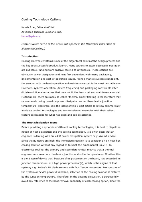
Cooling Technology OptionsKaveh Azar, Editor-in-ChiefAdvanced Therm al Solutions, Inc.kazar@(Editor's Note: Part 2 of this article will appear in the November 2003 issue of ElectronicsCooling.)IntroductionCooling electronic system s is one of the m ajor focal points of the design process and the key to a successful product launch. Many options to attain successful operation are available, ranging from passive cooling to cryogenics. These options are obviously power dissipation and heat flux dependent with m any packaging, implem entation and cost-of-operation issues. From a m arket success standpoint, the solution with the least operation and m aintenance cost is the m ost desirable one. However, system s operation (device frequency) and packaging constraints often dictate solution alternatives that m ay not fit the least cost and m aintenance m odel. Furthermore, there are m any so-called "thermal limits" floating in the literature that recommend cooling based on power dissipation rather than device junctiontem perature. Therefore, it is the intent of this 2-part article to review comm ercially available cooling technologies and to cite selected exam ples with their salient feature as beacons for what has been and can be attained.The Heat Dissipation IssueBefore providing a synopsis of different cooling technologies, it is best to dispel the notion of heat dissipation and the cooling technology. It is often seen that an engineer is dealing with an x-kW power dissipation system or y-W/cm2 device. Since the num bers are high, the immediate reaction is to consider a high heat flux cooling solution without any regard as to what the fundam ental issue is. In electronics cooling, the primary and secondary critical m etrics that a therm al engineer must m eet are the device junction and solder temperatures. Whether this is a 0.5 W/c m2 device that, because of its placem ent on the board, has exceeded its junction tem perature, or a high power processor(s), which is the engine of that system; e.g., today's 1U blade servers with four Xenon processors. Irrespective of the system or device power dissipation, selection of the cooling solution is dictated by the junction tem perature. Therefore, in the ensuing discussion, I purposefully avoid any reference to the heat rem oval capability of each cooling option, since thecapacity is temperature and space dependent. Further, making any reference to heat rem oval capacity can be misleading.When we look at the heat transport vehicles available in t he m arket, it is quite clear that the technology is well established and extensively docum ented. However, a series of questions are generated when attem pting to transfer this technology to electronics system s. These are:1.Would there be sufficient space to provide a large surface area for heattransfer, or to implement thermal transport (e.g., heat pipe) devices to take the heat out of the system?2.Can we use fluids with higher thermal capacitance/conductivity andsubsequently higher "h" to attain the desired cooling? Would the cost of such fluids allow their implementation in the m arket place?3.Would the existing system packaging allow the use of a higher capacitycooling system?4.Would the m arket be open to a system that is m echanically much m orecom plex and maintenance dem anding than a "simple" air mover?With these questions in mind, the cooling technology can be divided into two broad categories.A. Passive cooling, where nature does the fluid movement (e.g., natural convection) or energy is transported by conduction and/or radiation heat transfer.B. Active cooling, where the fluid m otion is assisted by an external source, a fan in a forced air cooled system, or pump and fan of an immersion or refrigeration cooled system.Considering the four questions that I raised, it is clear that option A is the m ost desired solution from the product standpoint since it has the leastimplem entation-cost and requires, effectively, no m aintenance. However, as the power dissipation increases and packaging space becom es l imited (question 1), option B begins to take hold and becom es the m ethod of choice despite its higher implem entation cost and concerns for the operational reliability.Cooling SystemsWith these two broad categories in mind, let's look at the cooling options that have been developed in the industry.Passive CoolingPassively cooled system s take advantage of all m odes of heat transfer for thermal transport. At the system level, typically, large heat sinks with wide fin-to-fin spacing are used for cooling. Television sets, set-top boxes, pole- or strand-m ounted telecommunications boxes are some of the typical examples in this category. In passively cooled system s, designers typically attem pt to utilize conduction and radiation as the primary m odes of heat transfer to m aximize the therm al transport and to induce higher levels of natural convection. In applications where convection is limited, e.g., space shuttle cooling, radiation heat transfer becom es the sole mode of transport of heat from the source to the sink - space, in the case of the shuttle.Passively cooled devices take advantage of a heat spreader (a conductive plate to spread the heat) and/or heat sinks specifically designed for such conditions. Similar to system s, m aximizing radiation and conduction heat transfer from the device is key for reaching higher levels of power dissipation while meeting device junction tem perature constraints. In space limiting applications, e.g., laptops, heat pipes are often used to efficiently transport the heat from the device to a location where a larger space is available (Figure 1).Figure 1. Heat pipe and heat spreader com bination. (Courtesy of Enertron Corp.)Active CoolingThis class of solutions encom passes an array of cooling techniques that are diverse and extensive. It is not the intent to review each individual cooling solution, ratherto highlight what is available and to provide the salient features of each option. In a broad sense, the cooling options can be categorized as follows:Heat Sinks and Fan-Sinks without Heat PipesExtended surfaces, so-called heat sinks, are by far the m ost commonly used cooling solutions in the electronics industry. The designs, m anufacturing techniques, and materials used in their construction are as diverse as the designers who m ake them. Conventionally they are used in system s with air movers. At tim es, because of airflow inadequacy or spatial constraints, a fan m aybe mounted on the heat sink, the so-called fan-sink. Or, a heat pipe is also used along with the heat sink to improve therm al transport. The interfacial and spreading resistances in addition to the attachm ent, as well as designing the heat sink for the right location on a PCB, are the points of contention.Fluid Flow Management and EnhancementAlthough this by itself can not be considered as a stand alone cooling solution, board and system level fluid flow m anagement has shown great promises. The t echnique involves looking at the flow distribution in the region of interest and attem pting to change the layout, whether a board or system, to rem ove flow stagnation points. As a result, whether a component on a PCB or a PCB in a system, it will have a significantly improved flow-exposure that can often result in the elimination of heat sinks or a lesser capacity cooling solution (Figure 2). This is an area that is often ignored since board or system re-layout are costly if fluid flow optimization is not done a priori.Figure 2. Water flow visualization of a flow over a PCB. On the left, the original layout shows multiple stagnation points. On the right, the flow-optimized layoutshows minimal stagnation points. (From the author's short course: "ExperimentalMethods in Electronics Cooling.")Hybrid CoolingThis simply implies a com bination of liquid and air cooling for high power dissipation electronics, while minimizing contact resistance throughout the system. In this process, the avionics industry has made great strides and produced cooling system s capable of rem oving high heat fluxes. Figure 3 shows one such system [1].Figure 3a, shows a rack/card guide system where the liquid is flowing through the card rack. The heat that is generated within the PCB is conduction through the solid core to the rack where the liquid is used as the transport vehicle to rem ove it from the system. The illustration on the right in Figure 3a shows a thru-card schem e where the PCB core is chambered for fluid passage. Thus the conduction heat transfer from the PCB to the rack, as shown in the figure on the right, is eliminated.Figure 3a. Two hybrid system s for an avionics application: On the left, edge liquid cooling; on the right, thru-card liquid cooling [1].Figure 3b shows the extensive packaging required to m ake such system s happen. Tightly sealed joints and mechanical contacts with least resistance are required to attain the level of therm al performance required for such a cooling option.Figure 3b. Card and rack level packaging required for hybrid cooling [1].Although I have purposefully avoided the discussion of cooling capacity, the exception to the path m ay be m erited here since these system s are not commonly encountered nor discussed in the open literature. Therefore, Figure 4 shows the removal capabilities of the hybrid system s for different cooling arrangements [1].The data depicted in Figure 4 clearly show the advantage of, say, subcooled jet impingement and a conventional cooled system, approximately a factor of 13! However, one cannot overlook the packaging requirements to deliver such a cooling solution, as shown in Figure 3b. The cost of these requirem ents and the attainm entof a high reliability cooling system may not m ake these system s suitable for typical commercially available electronics.Figure 4. Heat removal capacity for different hybrid system as com pared with aconvection cooled system. [1]Thermoelectric Cooler (TEC)TECs are electronic refrigerators that use the electrons to carry energy between the source and sink. The notion of a pump-less refrigerator, albeit highly inefficient, is an attractive concept. However, as shown by a number of researchers in the field, the promise of the TEC being an effective system level cooling solution has not materialized [2]. However, the TEC has been shown to be an enabling technology for spot cooling. One area that has benefited greatly from TEC is optical devices where maintaining a laser tem perature at a set level is a must for proper device operation. Poor device efficiency (30-50%) and reliability are the two limiting factors in the use of TECs in the industry.(End of Part 1)In Part 2 of this article, which will appear in the next issue, we will conclude with a discussion of Closed Loop Cooling, Thermosyphons, Direct Immersion with and without Boiling, Refrigeration Cooling System s, Cryogenics Cooling, and Conclusions.Kaveh Azar, Ph.D.Advanced Therm al Solutions, Inc.89 Access Road #27Norwood, MA 02062Tel: +1 781-769-2800Fax: +1 781-769-9979Em ail: kazar@References for Part 11. Mudawar, I., "Assessment of High-Heat-Flux Thermal managem ent Schem es", Proceedings of ITHERM, Las Vegas, NV, USA, 2000.2. Simons, R., "Application of Thermoelectric Coolers for Module Cooling Enhancem ent", ElectronicsCooling, Vol. 6. No. 2., pp. 18-24.Cooling Technology Options, Part 2Kaveh Azar, Editor-in-ChiefAdvanced Therm al Solutions, Inc.kazar@(Editor's Note: Part 1 of this article appeared in the August 2003 issue of ElectronicsCooling. Illustration references in this part begin with Figure 5.)IntroductionCooling electronic system s is one of the m ajor focal points of the design process and the key to a successful product launch. Many options to attain successful operation are available, ranging from passive cooling to cryogenics. These options are obviously power dissipation and heat flux dependent with m any packaging, implem entation and cost-of-operation issues. From a m arket success standpoint, the solution with the least operation and m aintenance cost is the m ost desirable one. However, system s operation (device frequency) and packaging constraints often dictate solution alternatives that m ay not fit the least cost and m aintenance m odel. Furthermore, there are m any so-called "thermal limits" floating in the literature that recommend cooling based on power dissipation rather than device junctiontem perature. Therefore, it is the intent of this 2-part article to review comm ercially available cooling technologies and to cite select examples with their salient feature as beacons for what has been and can be attained.In part 1 of this article, which appeared in the previous issue, we discussed: The Heat Dissipation Issue, Cooling System s (both passive and active), Heat Sinks and Fan Sinks without Heat Pipes, Fluid Flow Management and Enhancem ent, Hybrid Cooling, and Thermoelectric Coolers (TEC).Closed Loop Liquid CoolingThis is defined as a high capacity, high maintenance cooling system that uses liquid as the coolant and a heat ex changer for heat rem oval from the coolant. Figure 5 shows a schem atic drawing and typical implementation of such a system [3].Figure 5. A closed loop liquid cooling solution. The module at the lower left em ploys liquid jet impingement cooling. The m odule at the lower right uses spray cooling andrepresents an SGI Cray design [3].Different packaging schem es m ay put these cooling system s in other categories, but, in general, the use of closed liquid loops distinguishes these cooling system s from others. The predecessor for this cooling technique and perhaps the first commercial introduction of closed liquid loops in modern electronics (beyond vacuum tubes) is the IBM Thermal Conduction Module (TCM). In this system, a series of spring loaded cylinders conduct the heat from chips to the cooling cham ber. Such cooling solutions are currently used in high priced, large capacity com puters that can allow for the types of packaging and maintenance required to run these system.Figure 6. A thermosyphon cooling system. (Courtesy of Therm acore Corp.)ThermosyphonsThese are heat "transport" system s that use gravity to transfer heat from the source to sink. Although they are transport devices because of their implementation, they can be put into a category of a cooling solution. Figure 6 shows one such a system. The features of the system can be summarized as follows:∙Requires no pump and reservoir/expansion tank, com pared to closed loop cooling solutions.∙Can be m ade compact, so that the evaporator is the size of the m odule.∙Sensitive to orientation and internal fouling.Plumbed system, subject to shock/vibration, leakage, and potential dry-out.Direct Immersion with and without BoilingIn these system s the electronics is immersed in a Fluorinert liquid or mist to transfer the heat from the source to the sink. These are high capacity cooling system s that were deployed with limited success in the industry. The m ost fam ous such system - and som e examples are still in operation - is the Cray super com puter. Theoretically, the m ethodology is perhaps the best technique because the heat source is in direct contact with a high thermal capacity coolant, thus eliminating the nagging interfacial and spreading resistances that are the direct by-product ofconduction-to-convection cooling schem es. Figure 7, shows one such example of immersion cooling from IBM [4].Figure 7. IBM immersion cooling system with liquid or air cooled system s to removethe heat absorbed by the coolant [4].In these system s, depending upon the design and the choice of the coolant, boiling may occur. Research has shown that despite the high heat transfer offered by boiling, coolant fouling is a major concern with a poor reliability implication both for the coolant and the system where the fouling emanates. Irrespective, one can conclude that m ajor packaging, cost, and reliability issues are associated with such system s.Refrigeration Cooling SystemsThis is a relative newcom er to the electronics industry, finding a home in high speed microprocessors. In these system s, sub-cooling is necessary to attain the desired device frequencies. Kryotech is one of the first companies to have introduced refrigeration cooling to the commercial market. Figure 8 shows such a system where a simple, yet novel concept - a refrigeration unit of a size that would typically be used in a dorm room - is used to cool a high-speed m icroprocessor. The evaporator of the refrigerator is placed on the microprocessor to m aintain it at the desired tem perature.Figure 8. The first commercially available refrigerated processor.(Courtesy of Kryotech.)To im plement a refrigeration cooled system, the cycle and process look very similar to what has been commercially available for many years, Figure 9 [3].Figure 9. The com ponents required to form the refrigeration cycle.(IBM High End Z-Server, [3].)A number of system s have com e to the m arket that cover the full spectrum of products. These include individual PC level system s, rack level refrigeration for telecomm equipment, and high capacity (20kW) refrigeration system s. However, as much as the notion of sub-cooling is attractive for reaching the desired device frequencies, the issues of packaging, cost and reliability of m echanical system s continue to cast doubt on the use of such system s in commercial electronics.Cryogenics CoolingThis is perhaps the last frontier in cooling. The system is immersed in cryogenic fluids (e.g., liquid nitrogen) for cooling of super high heat flux devices that require low operating tem peratures. Despite a couple of failed commercial products, cryogenic cooling never found its application in the commercial market place. This failure was attributed to high operating cost, m ajor reliability issues (thus multiple down tim es), and high product cost due to custom development.Reliability issues are uniquely different as they pose the opposite problem to heat. At very low tem peratures, m aterial characteristics are different, and a host of new failure mechanisms with commercial m aterials are encountered. Therefore, to implem ent such a cooling system, a departure from conventional packaging is required. This causes a system to be costly for t ypical commercial use. Cryogenically cooled system s are typically associated with m ilitary and space electronics that can tolerate the high degree of customization and system cost.ConclusionsIn reviewing the broad scope of available cooling solutions, two points have becom e apparent.1.System s with tremendous heat dissipation have been designed andsuccessfully launched in the m arket place. Thus, a broad range of coolingsolutions do exist. Barring som e of the basic physics associated withcryogenics and boiling heat transfer, the underlying principles andfundamentals are also well understood. Therefore, when one is faced with a large heat flux at the device level or overall system power dissipation, areview of the literature and common practi ces is perhaps the best starting point.2.For every high capacity cooling system, whether hybrid or refrigerationcooling, the biggest bottleneck is the packaging. High capacity coolingsolutions do require a departure from conventional packaging techniquesused in the commercial (large m arket) electronics. This is a m atter thatcannot be taken lightly since for the commercial electronics,least-tim e-to-m arket and product-cost are the two prim ary drivers.To expand on the second point, although there are m any excellent works taking place to advance the cooling options, e.g., acousti c com pression (replacing mechanical com pressors), thermionics, device level electronic refrigeration, etc., the commercial electronics m arket is basically cost driven. Thus, air cooling and options to enhance its capacity should not be overlooked. Often, som e upfront engineering m ay avoid the large challenges of high capacity cooling solutions for a market that is not acclimated to these requirements. Considering that the selection of a cooling system is market driven rather than a m atter of best practices, the successful design is the one that gets the product into the m arket first with the least cost.Kaveh Azar, Ph.D.Advanced Therm al Solutions, Inc.89 Access Road #27Norwood, MA 02062Tel: +1 781-769-2800Fax: +1 781-769-9979Em ail: kazar@References for Parts 1 and 21. Mudawar, I., "Assessment of High-Heat-Flux Thermal managem ent Schem es", Proceedings of ITHERM, Las Vegas, NV, USA, 2000.2. Simons, R., "Application of Thermoelectric Coolers for Module Cooling Enhancem ent", ElectronicsCooling, Vol. 6. No. 2.3. NEMI 2000, Electronics Industry Roadmap, VA, USA.4. Chu, R., A personal communication.。
我想发明一个空调手表作文

我想发明一个空调手表作文英文回答:Inventing a wristwatch that is capable of air conditioning is an ambitious undertaking that requires a deep understanding of thermodynamics, microelectronics, and materials science. The challenges involved in developing such a device are significant, but not insurmountable.One of the primary challenges in designing an air-conditioned wristwatch is the need to generate cooling power in a compact and efficient manner. Traditional air conditioning systems rely on bulky compressors and condensers, which are not feasible for a wristwatch. To overcome this limitation, alternative cooling technologies, such as thermoelectric coolers or miniature vapor compression cycles, must be explored.Another challenge lies in managing the heat generated by the cooling system. As the watch operates, it willproduce waste heat that must be dissipated to prevent overheating. This can be achieved through the use of heat sinks or heat pipes, which can transfer heat away from the watch's components and into the surrounding environment.In addition to cooling challenges, there are also challenges related to power consumption, battery life, and user comfort. An air-conditioned wristwatch must be able to operate for an extended period of time without requiring frequent recharging. This requires careful optimization of the cooling system and the use of energy-efficient components. Furthermore, the watch should be comfortable to wear, even when the cooling system is operating. This involves considerations such as weight, size, and the materials used in the watch's construction.Despite these challenges, the development of an air-conditioned wristwatch is a promising area of research. Such a device could provide significant benefits to usersin hot and humid climates, offering a wearable solution to personal cooling.中文回答:发明一款具备空调功能的手表是一项雄心勃勃的壮举,需要对热力学、微电子学和材料科学有深入的了解。
冬奥会黑科技英文介绍作文

冬奥会黑科技英文介绍作文下载温馨提示:该文档是我店铺精心编制而成,希望大家下载以后,能够帮助大家解决实际的问题。
文档下载后可定制随意修改,请根据实际需要进行相应的调整和使用,谢谢!并且,本店铺为大家提供各种各样类型的实用资料,如教育随笔、日记赏析、句子摘抄、古诗大全、经典美文、话题作文、工作总结、词语解析、文案摘录、其他资料等等,如想了解不同资料格式和写法,敬请关注!Download tips: This document is carefully compiled by theeditor. I hope that after you download them,they can help yousolve practical problems. The document can be customized andmodified after downloading,please adjust and use it according toactual needs, thank you!In addition, our shop provides you with various types ofpractical materials,such as educational essays, diaryappreciation,sentence excerpts,ancient poems,classic articles,topic composition,work summary,word parsing,copyexcerpts,other materials and so on,want to know different data formats andwriting methods,please pay attention!The Winter Olympics is known for its cutting-edge technology, and this year's event is no exception. From innovative equipment to advanced data analysis, the Games have showcased some truly mind-blowing inventions. Let's take a look at some of the coolest "black technology" that has been on display.In the world of winter sports, safety is always a top priority. That's why the introduction of smart helmets has been a game-changer. These helmets are equipped with sensors that can detect impacts and immediately send an alert to the wearer's phone. This technology not only helps athletes stay safe but also allows coaches and medicalstaff to monitor their well-being in real-time.Another fascinating piece of technology is the virtual reality training system. Athletes can now simulate their competition environment and practice their moves without even leaving the training facility. This immersiveexperience not only saves time and money but also allows athletes to perfect their skills in a controlled and safe environment.When it comes to ice sports, precision is key. That's where the laser ice-measuring system comes in. Instead of relying on manual measurements, this technology uses lasers to accurately measure the thickness and flatness of the ice. This ensures that the playing surface is fair for all athletes and eliminates any potential advantages or disadvantages.In the world of skiing, aerodynamics play a crucialrole in performance. That's why the introduction of thewind tunnel testing system has been a game-changer.Athletes can now test their equipment and body positions in a controlled environment, allowing them to make adjustments and optimize their performance on the slopes. This technology has revolutionized the way skiers approach their training and preparation.Data analysis has also played a significant role inthis year's Winter Olympics. With the help of artificial intelligence and machine learning algorithms, coaches and athletes can now analyze vast amounts of data to gain insights and make informed decisions. From analyzing an athlete's performance to predicting weather conditions,this technology has revolutionized the way teams preparefor competitions.In conclusion, the Winter Olympics has showcased some truly mind-blowing "black technology" this year. From smart helmets to virtual reality training systems, these inventions have revolutionized the way athletes train and compete. With the help of advanced data analysis and precision measuring systems, athletes can now push the boundaries of what is possible in their respective sports. The future of winter sports is undoubtedly exciting, and we can't wait to see what innovations the next Winter Olympics will bring.。
博卡电焊机 生成器说明书

Issued February 2018 • Index No. ED/4.4Welder/generator is warranted for three years, parts and labor. Engine is warranted separately by the engine manufacturer.Easier mobility and uses less truck space and payload With its intuitive design, the daily maintenance of our Bobcat welder/generators is faster and easier.Easier Maintenance Safer, more productiveBobcat 250 EFI model shown.The most popular welder/generator • Quieter to operate • Smaller and lighter• More fuel efficient with EFI • Easier to maintainGas or LP Engine-Driven Welder/AC GeneratorBobcat225and 250Miller Electric Mfg. LLCAn ITW Welding Company 1635 West Spencer Street P.O. Box 1079Appleton, WI 54912-1079 USAEquipment Sales US and CanadaPhone: 866-931-9730FAX: 800-637-2315International Phone: 920-735-4554International FAX: 920-735-4125Rugged welder/generators are great for stick and flux-cored welding.Designed for maintenance/repair operations, construction, farm,ranch and generator use.The Bobcat™AdvantageDesigned for reliabilityFrom Appleton, Wis. USA, our welder/generators are the most rugged, durable and long-lasting in the industry. We manufacture them to exceed requirements for extreme working conditions and they are hard-working from the core:•Copper windings and iron generator components for a quality-built machine •Lugged—not soldered—heavy internal leads for better field durability •Superior cooling technologyfor maximum performanceand engine life•Super-tough armor toprotect the welder/generator from accidental impact•Protective armor doors to cover the weldstuds and receptacles as required by OSHAand CSA for jobsite safety•Lift hook integrated into the center frame,which bolts to the machine’s base forgreater durabilityLong runtimesLarge 12-gallon fuel capacity means manyhours of run time before refueling.Versatile AC and DC weld outputProvides quality welds on all types of metals.DC is smooth and easy to run while AC stickis used when arc blow occurs.Quieter and better sound*Significant improvements in soundlevel and quality offer better jobsitecommunication, which provides a safer,more efficient working environmentfor you and your crew. Bobcatwelder/generators have rotated theengine toward the front to create moreefficient airflow, resulting in significantly quieter operation. Now you can start your job earlier in the day and end it later, as well as work around hospitals, businesses, and residential areas.Smaller and lighter design*Bobcat welder/generators take up lessspace on trucks and trailers—leavingmore room on your truck for otherequipment and tools. Plus, they’reeasier to move safely around jobsites—even with weld cables and runninggear attached.*Compared to previous model Easier maintenance*With its intuitive design, the daily maintenance of our Bobcat welder/generators is faster and easier. With front panel maintenance displays, you know when your equipment needs to be serviced. And servicing is simple because of:•Oil checks that can be performed from the top by the front panel •Toolless panels that allow for quick access•Single-side fuel fill and oil drain/filterS fEasier mobilit andAir filterOil fill Oil drain Oil level checkFuel fill Oil filterFuel filter•Front panel fuel and sight gauges provide convenient fuel level indication•Smoother weld output and better generator power while welding •More weld output than 225-amp welder generators—72 percent more power for MIG/flux-cored, 67 percent more for AC welding, and 11 percent more for DC stick Electronic fuel injection (EFI)EFI gas engines optimize the air/fuel ratio forall engine speeds and engine loads, resultingin lower operational costs, fewer emissions, longer runtimes and better performance when compared to carbureted models. TheBobcat™250 Additional FeaturesBobcat 250 recommended option2Exclusive engine and generator packaging design operates cooler and more efficientlyThe engine is rotated towards the front to create more efficient airflow. More efficient airflow and exclusive engine location are significant contributors to reduced sound level and size reduction.Hot air recirculation is eliminated when machine is mounted in tight spots, and internal parts are kept cool for optimal performance.3Reversed Generator AirflowTo select a generator that has enough power output in watts, add the watts for the items you want tosimultaneously run. Tools and appliances with induction motors may require three to seven times the listed wattage when starting. All data listed is approximate —check your tool/appliance for specific wattage requirements.Starting Running Equipment Watts Watts Barn Cleaner (5 hp) 11,600 3,000Silo Unloader (5 hp) 12,200 4,300Portable Conveyor (1/2 hp) 3,400 1,000Milker (5 hp) 10,500 2,800Hand Drill (1/2 inch) 600 600Circular Saw (8-1/4 inch) 1,400 1,400Air Compressor (1-1/2 hp) 8,200 2,200Flood Lights (Vapor) 1,250 1,000Refrigerator/Freezer 2,200 700Sump Pump 1,300 800Millermatic ®212 Auto-Set ™ 6,500 6,500MIG Welder (230 V)Spectrum ®625 X-TREME ™ 6,900 6,900(30 A, 230 V, 1/2-inch cut)The Bobcat ™Generator Power AdvantageAccu-Rated ™—not inflated generator powerOur Accu-Rated ™11,000 watts (12,000 with EFI)of usable peak power isdelivered for a minimum of 30 seconds. Accu-Rated means peak power is usable for maximum generator loads such as plasma cutting, Millermatic ®MIG welders and motor starting. Accu-Rated peak power beats the competition’s very short-duration peak or surge power. Use your peak power, it’s more than a number.Smooth power —not spike powerRevolutionary ten-degree skewed-rotor design optimizes generator performance for smootherpower —not spiked power found with other brands. Better power —better performance.Typical equipment power usageBobcat welder/generators will easily start and run the following equipment:Waveform ComparisonBobcatCompetitorTools and motors are designed to operate within 10 percent of 120/240 V. The powergenerator of the Bobcat provides strong power while keeping the voltage within 10 percent of 120/240 V.This increases tool/motor performance and life.Generator Power Curve10203040506070809010011020406080100120140160180200220AC Power Amps at 120 V025*******108125150050100150200216132264250300A C P o w e r V o l t sAC Power Amps at 240 V4Engine Specifications (Engines warranted separately by the engine manufacturer.)Model Bobcat 225Bobcat 250Welding Mode CC/AC CC/DC CV/DCCC/AC CC/DC CV/DCProcess Stick/TIG Stick/TIG 1MIG/FCAW Stick/TIG Stick/TIG 1MIG/FCAWRated Weld Output at 104°F (40°C)2150 A at 25 V, 100% duty cycle 225 A at 25 V, 100% duty cycle 200 A at 20 V, 100% duty cycle 225 A at 25 V, 100% duty cycle 250 A at 25 V, 60% duty cycle 250 A at 25 V, 100% duty cycle 250 A at 28 V, 100% duty cycle 275 A at 25 V, 60% duty cycleAmp/Volt Ranges 60–160 A 40–225 A 19–28 V 40–250 A 40–250 A 17–28 VSingle-Phase Generator Power Peak: 11,000 wattsContinuous: 9,500 watts 120/240 V, 88/44 A, 60 HzPeak: 11,000 wattsContinuous: 9,500 watts 120/240 V, 88/44 A, 60 Hz EFI ModelPeak: 12,000 wattsContinuous: 10,500 wattsSound Levels at Max. Load/150 A 73.5 dB/72 dB72.5 dB/72 dBNet Weight 3485 lb. (220 kg)501 lb. (227 kg)Dimensions H: 28 in. (711 mm)H: 32.75 in. (832 mm) (to top of exhaust)W: 20 in. (508 mm)D: 40.5 in. (1,029 mm)H: 28 in. (711 mm)H: 32.75 in. (832 mm) (to top of exhaust)W: 20 in. (508 mm)D: 40.5 in. (1,029 mm)Certified by Canadian Standards Association to both the Canadian and U.S. Standards.Note: Derate outputs up to five percent when using LP fuel. 1) DC TIG available above 80 amps. 2) Rated at sea level. 3) Net weight without fuel.*Fuel stabilizer is recommended for gas engines that are used infrequently.**Hose and LP Tank Mounting Assembly and setup are required.Performance DataMounting SpecificationsA.20 in. (508 mm)B.16.5 in. (419 mm)C.1.75 in. (44.5 mm)D.5.12 in. (130 mm)E. 22.3 in. (566 mm)F. 40.32 in. (1,024 mm)G..406 in. (10.3 mm) diameterF r o n t P a n e l0.000.250.500.751.001.251.501.752.0005010015020025030024681012Fuel ConsumptionPower KVA at 100% Duty CycleWeld Amperes at 100% Duty CycleU .S . G a l./h o u rFuel Consumption Data•12-gallon fuel capacity.•On a typical job using 1/8-inch 7018electrodes (125 A, 20% duty cycle) expect about 20 hours (gas) of operation.•Welding at 150 A, 40% duty cycle uses approxi m ately 3/4 gallon per hour —about 16 hours of operation (gas).•Under a continuous load of 4,000 watts of generator power, the Bobcat would run for about 14 hours (gas) of operation.5Note: See or the Full-line Catalog to compare to Trailblazer models.Function and Benefit Guide1.Maintenance display provides fuel level (250 models only), engine hours and oil change interval information.2.Weld process selector switch makes choosing between stick, wire and TIG processes easy. Switch also auto m atically changes polarity with process selection to make sure the machine is easy to set with little effort or knowledge (on 225 model, weld process selector switch is combined with coarse range control).3.Coarse range control225 model —Three DC stick/TIG, one AC TIG, and one wire range are available for output control. Stick ranges are designed forelectrode diameters (3/32, 1/8 and 5/32 inch) making these models very easy to set.250 model —Four stick/TIG and two wire ranges are available for output control. Stick ranges are designed for electrode diameters (3/32, 1/8, 5/32 and 3/16 inch) making these models very easy to set.4.Fine adjust control makes it easy to fine tune amperage within a coarse range. Set control above 7 for best power while welding and to 10 for generator-only use.5.Engine control switch is used to start the engine and then select between auto idle and high speed lock positions.6.Engine choke control is used for easy engine starting.Note: No choke necessary on EFI models.7.120/240 V receptacle with circuit breaker.(For matching plug, order 119172.)8.120 V GFCI receptacles with circuit breakers.Choose the Right Bobcat ™Engine Drive6Order the following from Miller Service Parts.Genuine Miller ®Options *Available as factory option. See ordering information on back page.Genuine Miller ®AccessoriesNever Flat ™TiresAvailable on Bobcat and Trailblazer running gear.•Eliminate costly jobsite downtime•Maintain constant tire pressure and will not develop flats•Protect against punctures•Preserve maneuverability, even when weighed down with heavy welding cable Off-RoadRunning Gear 300909 Gas/LP, with inner tubes 300910 Gas/LP, with Never Flat tires Includes fourheavy-duty 15-inch tires and a rugged handle to provide maximum maneuverability.Off-Road Running Gear withProtective Cage and Never Flat Tires300912 Gas/LP Running gear and rugged cage withcable holders protects your investment and is easy to move around the jobsite.Multi-Terrain Running Gear 300913 Gas/LP,with inner tubes 300914 Gas/LP,with Never Flat tires Includes two heavy-duty 15-inch tires, two 8-inch rubber swivel casters and a heavy-duty handle. Recommended for all surfaces and applications, and is easy to move around the jobsite.Protective Cagewith Cable Holders 300921Gas/LP Rugged cage with cable holders protects yourinvestment. Can beused with running gear, gas cylinder mounting assembly, LP tank mounting assembly, or with trailer.Gas CylinderMounting Assembly 300918GasDesigned for use with multi-terrain running gear, protective cage, or by itself. Includes base tray with bottlebracket, vertical support rack and safety chain.Note: Not for use with LP tank mounting assembly.Not recommended for use with protective cover.Hose and LP Tank Mounting Assembly 300917LPDesigned for use with multi-terrain running gear, protective cage,or by itself. Includes bracket and clamp tomount 33- and 43-pound tanks horizontally, and hose with fittings to converter.Note: Not for use with gas cylinder mounting assembly.Not recommended for use with protective cover.Protective Covers 300919 For gas models without protective cage or running gear (shown)300920 For gas models with protective cage and/or running gearHeavy-duty, water-resistant and mildew-resistant covers protect and maintain the finish of the welder.7MIG/Flux-cored WeldingMillermatic 141 and 211 shown.Millermatic ®141 907612See literature DC/12.42Millermatic ®211 907614See literature DC/12.58Millermatic ®212 Auto-Set ™907405See literature DC/12.46The Millermatic line of MIG welders are complete arc welding power source, wire feeder and gun packages designed for portability and ease of use.Note: The Millermatic machines can be operated utilizing auxiliary power.SuitCase ®X-TREME ™8VS Wire Feeder 951582SuitCase ®X-TREME ™12VS Wire Feeder 951543Lightweight, voltage-sensing wire feeders include secondary contactor, gas valve, drive roll kit and Bernard ™BTB Gun 300 A. See literature M/6.42.Spoolmatic ®30A Spool Gun 130831Air-cooled, 200-amp,one-pound spool gun for aluminum MIG.See literature M/1.73.Requires WC-115A control (137546011).Spoolmate ™3035Spool Gun 195016Use with SGA 100C control and heavy-duty barrel. Spool gun for aluminum andother wires. Four-inch spools; .023–.035 inch (0.6–0.9 mm) aluminum, steel and stainless steel. Rated at 150 amps, 60 percent duty cycle with 20-foot (6 m) cable assembly.SGA 100C Control 043857SGA with contactor required to connectSpoolmate 3035 to CV engine drive. Includes 10-foot (3 m) 115 V power cable and plug, 6-foot (1.8 m) interconnecting cable, and 5-foot (1.5 m) gas hose.Heavy-Duty Barrel for Spoolmate 3035195375Use for demanding applications, rated at 200 A,60 percent duty cycle.Stick (SMAW) WeldingWeld Leads2/0 Stick Cable Set, 50 ft. (15 m) 173851Consists of 50-foot (15 m) 2/0 electrode cable with holder, and 50-foot (15 m) work cable with clamp. 350 A, 100% duty cycle.2/0 Stick Cable Set, 100/50 ft. (30.5/15 m)043952Consists of 100-foot (30.5 m) 2/0 electrode cable with holder, and 50-foot (15 m) work cable with clamp. 300 A, 100% duty cycle.TIG (GTAW) WeldingDynasty ®210 Series For portable AC/DC TIG. See literature AD/4.81.Multiprocess WeldingMultimatic ™200 907518Portable, all-in-one multiprocess package weighs only 29 pounds (13.2 kg), and features excellent arc characteristics. Exclusive multi-voltage plug (MVP ™) provides flexibility to plug into 120- or 240-volt power. Take it anywhere you need to MIG, TIG or stick weld. See literature DC/12.57.Plasma CuttingSpectrum 375 X-TREME and 625 X-TREME shown.Spectrum ®375 X-TREME ™907529See literature PC/9.2.Spectrum ®625 X-TREME ™907579See literature PC/9.6.Spectrum ®875 907583See literature PC/9.8.The Spectrum 375 X-TREME and 625 X-TREME come complete with protective X-CASE ™(not shown).Trailers and HitchesHWY-Mid Frame Trailer 3014381,424-pound (646 kg) capacity highway trailer with welded steel tubing frame, heavy-duty axle with roller bearing hubs and leaf-springsuspension. Includes jack stand, fenders, lights,and dual hitch with 2-inch (50 mm) ball hitch and 3-inch (76 mm) lunette eye.Note: Trailer is shipped unassembled.Cable Tree 043826Provides an area to conveniently wrap weld cables and extension cords.2-In-1 Document/Fire Extinguisher Holder 301236Stores documents and holds a five-pound fire extinguisher.Note: Holder shown mounted on trailer. Fire extinguisher notincluded.Genuine Miller ®Accessories (Continued)Ordering InformationEquipment and Options Stock No. Description Qty. PriceBobcat™225907498001Kohler engine, base model907498 Kohler engine with GFCI receptaclesBobcat™250907500001 Kohler engine, base model907500 Kohler engine with GFCI receptacles907500002 Kohler engine with electric fuel pumpBobcat™250 EFI 907502Kohler engine, base modelBobcat™250 LP 907504Kohler engine with GFCI receptaclesField Options Options listed below can be added to the above packages. Installation is required.GFCI Receptacles 300975Electric Fuel Pump 300976 Recommended for gas engine operations at altitudes above 5,000 feetSpark Arrestor300924Remote Oil Drain and Filter Kit 300923 Front mount for KohlerFull KVA Adapter Cord300517Full KVA Plug 119172Engine Tune-Up Kits See page 6. Order from Miller Service PartsAccessoriesOff-Road Running Gear300909Gas/LP models, with inner tubes300910Gas/LP models, with Never Flat™tiresOff-Road Running Gear with Protective Cage300912 Gas/LP models, with Never Flat™tires.Multi-Terrain Running Gear300913Gas/LP models, with inner tubes300914Gas/LP models, with Never Flat™tiresProtective Cage with Cable Holders300921 Gas/LP modelsGas Cylinder Mounting Assembly 300918 Gas models. Not for use with LP tank mounting assembly.Not recommended for use with protective coverHose and LP Tank Mounting Assembly 300917 LP models. Not for use with gas cylinder mounting assembly.Not recommended for use with protective coverProtective Covers See page 6MIG/Flux-cored WeldingMillermatic®Series MIG Welders See page 7SuitCase®X-TREME Wire Feeders See page 7Spoolmatic®30A Spool Gun 130831 Requires WC-115A Control. See literature M/1.73WC-115A Control 137546011 See literature M/1.73Spoolmate™3035 Spool Gun 195016 See literature M/1.5SGA 100C Control 043857 See literature M/1.5Heavy-Duty Barrel for Spoolmate 3035195375 See literature M/1.5Stick Welding See page 7TIG Welding See page 7Multiprocess Welding See page 7Plasma Cutting See page 7Trailers and HitchesHWY-Mid Frame Trailer301438Trailer with lights, fenders and dual hitch. For highway useCable Tree 043826Trailer-mounted cable holder2-In-1 Document/Fire Extinguisher Holder301236 Stores documents and holds a five-pound fire extinguisherDate: Total Quoted Price:Distributed by:©2018 Miller Electric Mfg. LLC。
- 1、下载文档前请自行甄别文档内容的完整性,平台不提供额外的编辑、内容补充、找答案等附加服务。
- 2、"仅部分预览"的文档,不可在线预览部分如存在完整性等问题,可反馈申请退款(可完整预览的文档不适用该条件!)。
- 3、如文档侵犯您的权益,请联系客服反馈,我们会尽快为您处理(人工客服工作时间:9:00-18:30)。
Exergetic comparison of two different cooling technologies for the power cycle of a thermal power plantAna M.Blanco-Marigorta *,M.Victoria Sanchez-Henríquez,Juan A.Peña-QuintanaUniversity of Las Palmas de Gran Canaria,Department of Process Engineering,Edi ficio de Ingenierías-Ta fira Baja,35017Las Palmas de Gran Canaria,Spaina r t i c l e i n f oArticle history:Received 14December 2009Received in revised form 11September 2010Accepted 18September 2010Available online 3November 2010Keywords:Exergy analysis Exergy destructionSolar thermal power plant Rankine cycle Cooling towerAir cooled condensera b s t r a c tExergetic analysis is without any doubt a powerful tool for developing,evaluating and improving an energy conversion system.In the present paper,two different cooling technologies for the power cycle of a 50MWe solar thermal power plant are compared from the exergetic viewpoint.The Rankine cycle design is a conventional,single reheat design with five closed and one open extraction feedwater heaters.The software package GateCycle is used for the thermodynamic simulation of the Rankine cycle model.The first design con figuration uses a cooling tower while the second con figuration uses an air cooled condenser.With this exergy analysis we identify the location,magnitude and the sources or thermo-dynamic inef ficiencies in this thermal system.This information is very useful for improving the overall ef ficiency of the power system and for comparing the performance of both technologies.Ó2010Elsevier Ltd.All rights reserved.1.IntroductionAs interest for clean renewable electric power technologies grows,a number of parabolic trough power plants of various con figurations are being considered for deployment around the globe.The first parabolic trough power plant in Europe,Andasol-1,in southern Spain,went into operation in November 2008and Andasol-2and Andasol-3are currently under construction.Each Andasol power plant consists of a solar field,a thermal storage tank and a conventional power plant section.The power cycle used in the Andasol plants is a traditional Rankine cycle.Induced draft cooling towers are used as condenser cooling tech-nology.The principal heat transfer process in a wet cooling tower is evaporation.As a result,approximately 1kg of water must be evaporated for each kilogram of steam condensed.Therefore water consumption can be signi ficant.For example:an 80MWe parabolic trough solar plant,operating with a capacity factor of 27%,will consume about 725tons of water per year [1].For sites which have a limited supply of water,water consumption adversely impacts the operating costs of the plant.There are alternative means for condensing steam that do not require makeup water.An A-frame air cooled condenser,for example,condenses steam through several finned tubes with forced air convection on the outer surfaces of the tubes.The primary advantage of air cooled condensing is the elimination of water consumption for cooling water makeup.Another advantage is the elimination of the cooling tower plume.Elimination of the cooling tower plume presents a unique bene fit at solar thermal power plants,as condensation from the cooling tower plume can reduce the optical ef ficiency of the solar collector mirrors closest to the cooling tower.The primary disadvantage of air cooled condensing is that heat transfer by forced air convection is a less effective heat transfer process than evaporative heat transfer.Therefore larger heat exchanger areas and greater fan power will be required to achieve heat rejection from the cycle comparable to the design state.The thermodynamic inef ficiencies associated with an energy conversion system are assessed with the aid of an exergy analysis conducted at the component level [2,3].The exergy analysis reveals two things:the destruction of exergy within a system component,and the exergetic ef ficiency,which in turn shows how effectively the exergetic resources supplied to a component have been used.Several previous exergy studies have evaluated the performance of thermal power plants.Sengupta et al.[4]conducted an exergy analysis of a 210thermal power plant.Habib and Zubair [5]per-formed a second law analysis of regenerative Rankine power plants*Corresponding author.Tel.:þ34928451934;fax:þ34928458975.E-mail addresses:ablanco@dip.ulpgc.es (A.M.Blanco-Marigorta),msanchez@ccc.es (M.Victoria Sanchez-Henríquez),jpena@dip.ulpgc.es (J.A.Peña-Quintana).Contents lists available at ScienceDirectEnergyjournal ho me page:www.elsevier.co m/locate/energy0360-5442/$e see front matter Ó2010Elsevier Ltd.All rights reserved.doi:10.1016/j.energy.2010.09.033Energy 36(2011)1966e 1972with reheating.Dincer and Muslim[6]conducted a thermodynamic analysis of reheat cycle power plants.Tsatsaronis and Winhold[7] presented a formulation on exergoeconomic analysis and evalua-tion of energy conversion plants applied to a Coal-Fired Steam Power Plant.In Ref.[8]exergetic and thermoeconomic analyses for a500-MW combined cycle plant were performed.More recently,Aljundi [9]presented an energy and exergy analysis of a steam power plant in Jordan.Related to solar thermal power plants,Singh et al[10] presented a second law analysis based on an exergy concept for a solar thermal power system.Singh et al evaluated the respective losses as well as exergetic efficiency for typical solar thermal power systems under given operating conditions.They found that the main energy loss takes place in the condenser of the heat engine,and their exergy analysis shows that the collector e receiver assembly is the part where the losses are maximum.Gupta and Kaushik[11]carried out the energy and exergy analysis for the different components of a proposed conceptual direct steam generation solar thermal power plant.In Ref.[12],a35MW solar thermal power plant was analyzed with the aid of exergoeconomics.This paper deals with the comparison of wet and dry cooling technologies for the power cycle of Andasol-1by means of exergy analysis.The solarfield is not considered in the study.Through an exergy analysis,the real thermodynamic inefficiencies(exergy destruction and exergy loss)of the power cycle are identified.This information,which cannot be provided by other means(e.g.an energy analysis),is very useful for improving the overall efficiency of the power system or for comparing the performance of both cooling technologies.The results obtained here are expected to provide information that will assist in decision-making regarding alternative cooling technologies.2.Description of the plantThe power plant has a net power capacity of50MWe.The cycle is a conventional,single reheat design withfive closed and one open extraction feedwater heaters.The GateCycleflow diagram is shown in Fig.1.In direct operation mode,a heat transferfluid(HTF,Therminol-VP1)is circulated through the solarfield to the steam generation system,where steam is produced at a temperature of373 C and at a pressure of100bar.The HTFfluid acts as the heat transfer medium between the solarfield and the power block;it is heated up in the solar collectors and cooled down while producing steam in the steam generator.The steam generation system consists of two parallel heat exchanger trains(preheater(ECON1)/steam generator(EVAP1)/superheater(SPHT1))and two reheaters (SPHT2),again connected in parallel.The superheated steam travels first through the high pressure turbine(ST1),where it expands and propels the turbine blades.One extraction is taken from the high pressure turbine to preheat feedwater in one closed feedwater heater(FWH5).On exiting the high pressure turbine,the steam is directed through a reheater,where it is superheated to approxi-mately the same temperature reached at the outlet of the super-heater(373 C)and at a pressure of about16.5bar.The superheated stream then passes through the low pressure steam(ST2e3),where again the steam expands and propels the turbine blades.Five steam extractions are taken from the low pressure turbine:one is directed to the deaerator(DA1)and the remaining four are fed to feedwater heaters(FWH1e4).The steam leaving the low pressure turbine,at 0.063bar,is condensed in a surface condenser by heat exchange with circulating water.The condenser water is cooled using an induced draft cooling tower.The condensed steam(feedwater)is pumped to a sufficiently high pressure(8.38bar)to allow it to pass through the three low pressure feedwater heaters and into the deaerator.The feedwater is pumped again at the outlet of the deaerator to a pressure slightly higher than the boiling pressure in the steam generator(103bar).Feedwater passes through the two high pressure feedwater heaters before returning to the preheater to complete the cycle.3.Thermodynamic evaluation3.1.Simulation and modellingThe software package GateCycle 5.61[13]was used for the thermodynamic simulation of the Rankine Cycle.Table1gives an overview on the main parameters and assumptions used in the thermodynamic simulation.Main plant operation data(detailed in Section2)were fed to the software as input variables.The results of the simulation were compared and validated using simultaneously plant operation data and EES Thermodynamic software[14].The thermodynamic properties were calculated based on: IAPWS IF97Steam Tables[15]for water,JANAF Tables[16]for ambient air and NIST Tables[17]for Therminol-VP1streams.The power cycle is modelled assuming that all components are adiabatic,except the steam generator system,and operatingat A.M.Blanco-Marigorta et al./Energy36(2011)1966e19721967steady state.Heat loss in the steam generator is calculated from plant operation data.Changes in potential and kinetic energy of fluid streams are assumed negligible.Gland steam production,as well as steam losses through line leaks,is neglected.Pressure losses in the steam lines to the feedwater heaters were set to zero.Also,negligible changes in fluid state between the outlet of one component and the inlet of the next are assumed.In addition,the following assumptions are made:feedwater exits the preheater as saturated liquid (x ¼0);steam exits the steam generator as satu-rated vapour (x ¼1);condensed steam exits the heater as saturated liquid (x ¼0);feedwater exits the deaerator saturated liquid (x ¼0);feedwater exits the condenser as saturated liquid (x ¼0).3.2.Evaluation of the condensing operation pressureFor the overall power process,the energetic ef ficiency is de fined by:h ¼_Wnet m 60ðh 63Àh 60Þþm 64ðh 65Àh 64Þ(1)where _Wnet includes the auxiliary elements of the cooling system studied in each case (refrigeration pump þcooling tower or air cooled condenser).The ef ficiency of a Rankine cycle is de fined,in large part,by the pressure and the temperature of the steam both entering and leaving the turbine.The steam conditions at the turbine outlet are de fined by the temperature at which the steam is condensed and the latent heat of vaporization can be transferred to the environ-ment.The lowest ambient temperature available is the wet bulb temperature;thus,most power plants use an evaporation process to provide the cooling water source for the condenser.For sites which have a limited supply of water,heat can be rejected to the environment by condensing turbine exhaust steam at the dry bulb,rather than the wet bulb,temperature.However,heat transfer by forced air convention is less effective than evaporative heat trans-fer;therefore,larger heat exchanger areas and greater fan power will be required to achieve the same heat rejection.For the Andasol-1design turbine exit pressure (0.063bar),energetic ef ficiency decreases from 34.2%to 32%when an air cooled condenser instead of a cooling tower is used.A con figu-ration with an air cooled condenser,even if it were possible to condense steam in the air cooled condenser at the ambient air temperature,would be inef ficient.The increase in gross power output from the cycle would be outweighed by the increase in parasitic fan power required to reach this temperature.In this paper,a comparison between dry and wet cooling technologies from an exergetic viewpoint is carried out with the consideration that both technologies,operating with similar parameters,not only reject the same amount of heat but also have the same net cycle power.It is necessary,therefore,to determine the turbine exit pressure with which both con figurations produce an as close as possible net cycle power.Fig.2shows the tendency of net cycle power with the increase of condensing pressure using both technologies.As condensing pressure increases,net cycle power of both technologies get closer.A condensing pressure of 0.2bar and,consequently,a net cycle power of 45MWe was chosen to perform the comparison.Higher condensing pressures only cause unnec-essary decrease in energetic ef ficiency.The condensing pressure of 0.2bar is neither a real operation pressure nor an optimum operation pressure proposal;it is only used for simulation and comparison purposes.This study does not include optimization of the design and con figuration of the air cooled condensing unit.The performance characteristics of an existing A-frame air cooled condensing unit [13]were used as reference.The thermodynamic properties oftheFig.1.GateCycle flow diagram 50MWe Rankine cycle with wet heat rejection.Table 1Main parameters and assumptions used in the thermodynamic simulation.Isoentropic ef ficiency of the high pressure steam turbine 0.852Isoentropic ef ficiency of the low pressure steam turbine 0.85Isoentropic ef ficiency of the pumps 0.75First extraction line inlet pressure (bar)33.5Second extraction line inlet pressure (bar)14Third extraction line inlet pressure (bar) 6.18Fourth extraction line inlet pressure (bar) 3.04Fifth extraction line inlet pressure (bar) 1.17Sixth extraction line inlet pressure (bar)0.37Terminal temperature difference in feedwater heaters ( C)4Drain cooler approach in feedwater heaters ( C)5Temperature of the thermodynamic environment ( C)25Pressure of the thermodynamic environment (bar)1Dry bulb temperature of ambient air ( C)20Relative humidity of ambient air (%)60Cooling tower approach ( C) 6.8Cooling tower range9.7A.M.Blanco-Marigorta et al./Energy 36(2011)1966e 19721968working fluid used in the frame air cooled condensing unit wereobtained on the basis of data provided by the GateCycle software.4.Exergy analysisIn an exergy analysis,an exergy balance is formulated for the k th component at steady state conditions:_E F ;k ¼_E P ;k þ_E D ;k þ_E L ;k(2)Here it is assumed that the system boundaries used for all exergybalances are at temperature T 0of the reference environment and thus there are no exergy losses associated with one component [18].Therefore the exergy destruction in the k th component is calculated only through the fuel and the product for the compo-nent.Exergy losses appear only at the level of the overall system,for which the exergy balance becomes:_EF ;tot ¼_E P ;tot þXk_E D ;k þ_E L ;tot(3)The exergetic ef ficiency of the k th component is:3¼_E P ;k _E F ;k ¼1À_ED ;k_E F ;k(4)In addition to the exergy destruction rate,_E D ;k,and the exergetic ef ficiency,the thermodynamic evaluation of a system component is based on the exergy destruction ratio,y D,k ,which compares theexergy destruction in the k th component with the fuel exergysupplied to the overall system,_EF ;tot :y D ;k¼_E D ;k_E F ;tot(5)This ratio expresses the percentage of the decrease in the overallsystem ef ficiency due to the exergy destruction in the k th system component:3tot¼_E P ;tot _E F ;tot ¼1ÀX ky D ;k À_E L ;tot _EF ;k(6)Alternatively,the component exergy destruction rate can be compared with the total exergy destruction rate within the system,_ED ;tot ,giving the ratio:y *D ;k ¼_E D ;k_ED ;tot (7)_E D ;k is an absolute measure of the inef ficiencies in the k thcomponent whereas 3k ,y D,k and y *D ;kare relative measures of the same inef ficiencies.In 3k the exergy destruction within a compo-nent is related to the fuel for the same component whereas in y D,k the exergy destruction within a component is related to the fuel forthe overall system.In y *D ;kthe exergy destruction within a compo-nent is related to the exergy destruction in the overall system.The characterization of fuel and product for a component is arbitrary but of capital importance in order to give an appropriate de finition of the exergetic ef ficiency.The product is determined by considering the desired result produced by the component and fuel by the resources expended to generate the result.In this study,fuel and product were calculated considering physical and chemical exergies of the material stream separately based on the de finitions given in [18].In the formulation of fuel and product for the cooling tower (Fig.3),it was necessary to split the physical and the chemical exergy of the stream of wet air in the respective parameters of the components:dry air (N 2,O 2,CO 2and Ar)and H 2O:_E F ;CT ¼_W FAN þÀ_E 33À_E 39ÁþÀ_E 37À_E 38Áþ_E 35À_E 34þ _E PHair ;50À_E PH air ;51 þ _E CH H 2O ;50À_E CHH 2O ;51 (8)_E P ;CT ¼_E CH air ;51À_E CH air ;50 þ _E PH H 2O ;51À_E PH H 2O ;50(9)Herein,the exergies of the flow streams (Tables 2and 3)were calculated according to the de finitions given in [19].For the speci fic physical exergy:e PH ¼ðh Àh 0ÞÀT 0ðs Às 0Þ(10)where subscript 0represents environmental conditions.The physical exergy was obtained based on the thermodynamic prop-erties calculated by GateCycle [13].The values of the standard chemical exergy of chemical compounds were taken from [20].The results of the thermodynamic analysis are shown in Tables 2and 3.5.Results and discussionTables 4and 5show the exergy destruction,exergetic ef ficiency and exergy destruction ratios for each main plant component.The results are presented in descending order of the parameter y *D ;k ,which compares the exergy destruction in the k th component444648505254560,060,080,100,120,140,160,180,200,22Pressure [bar]W[MW]Fig.2.Gross cycle power (),net cycle power with cooling tower ()and netcycle power with air cooled condenser (),versus condensing pressure (45MW).Fig.3.GateCycle schematic of a cooling tower.A.M.Blanco-Marigorta et al./Energy 36(2011)1966e 19721969with the exergy destruction in the overall process,_ED ;tot .As result,this parameter provides an insight into the exergetic meaning of each of the components of the overall system.Exergy destruction ratio in condenser working at 0.063bar and using a cooling tower represents only 6.8%of total exergy destruction whereas with an air cooled condenser it represents 25.5%of total exergy destruction.This result is mainly due to the huge amount of parasitic fan power required by the air cooled condenser to work under this pressure condition.Working at 0.2bar,both components (wet and dry condenser)present a comparable and high value of exergy destruction:32.73%the wet condenser and 31.11%the dry condenser.These values represent almost a third of the total exergy destroyed in the global system.Taking into account all the components that integrate the wet cooling technology (condenser,cooling tower and pump)it is necessary to sum the exergy destroyed in all the components.In this case,the exergy destructed ratio amounts to almost 12%operating at 0.063bar and 37.2%operating at 0.2bar.As a result we can say that,from an exergetic point of view,the use of an air cooled condenser is not an ef ficient solution working at low exit turbine pressures but it becomes more competitive at higher pressures.Exergy destructed in remaining components is not especially in fluenced by the use of different cooling technologies,apart from the condenser working pressure.The sequence followed bydifferent components regarding the value of y *D ;kis similar in both operation alternatives.Exergetic ef ficiency of each component assesses the fuel exergy wasted in the component as exergy destruction.Related to this concept,Tables 4and 5show the following:-The exergetic ef ficiency of the cycle is similar using both Technologies and working with the two pressure operation alternatives in the condenser:approximately 70percent.-Each component presents also a similar value of the exergetic ef ficiency with both technologies and working under both condenser pressure conditions:0.063e 0.2bar.The most important difference is presented in condenser:working at 0.063bar the exergetic ef ficiency of the wet condenser is 63.3%whereas the air cooled condenser presents an exergetic ef fi-ciency of 25.8%.Thermodynamic inef ficiencies associated with heat transfer are caused by mismatched heat capacity rates of the two streams and by a finite minimum temperatureTable 2Thermodynamic and exergetic data of streams for 0.063bar of condensing pressure._m(kg/s)T (C)p (bar)_E j(kW)_E j(kW)_E j(kW)160.08373.00100.0072,21012072,3302 6.25241.4633.486123126135353.83208.4818.5046,91310847,021453.83373.4016.5057,81110857,9195 2.70352.1213.992778527846 2.71254.59 6.182248522537 2.69186.44 3.0418******** 2.80108.24 1.171433614389 1.9673.990.37651.446551040.9637.050.0635518236331148.4237.050.0644.59971411248.4237.158.3885.74971821348.4262.698.28484975811448.4297.518.1815859716821548.42128.848.0830519731471660.08159.99 6.18607312061931760.08161.71103.00675912068791860.08189.68102.50921312093331960.08234.85102.0013,94112014,0622060.08309.00101.2024,34212024,4622160.08313.00101.0063,73712063,85722 6.25194.6833.38969.812982238.95166.7113.8999418101224 2.69102.51 2.9498.26510425 5.5067.69 1.0764.711176267.4642.150.2714.52152960533.40393.0015.80149,96819,854,63320,004,60161533.40381.0014.20140,70619,854,63319,995,33962533.40320.0012.6098,38319,854,63319,953,01763533.40301.0011.8086,68719,854,63319,941,3206468.50393.0015.8019,2562,549,7612,569,0166568.50225.0013.5060502,549,7612,555,811Cooling tower 332869.2236.23 1.88279057348524340.0636.250.950.050610.1150.1653532.8632.850.052002662068362836.1928.830.95293.4566859613765.7327.00 1.00 2.0241311333831.8128.790.95 3.226467392869.2028.790.95290.557346024402869.2028.80 1.88560.257346294501791.1728.050.952912,38412,413511824.0432.850.95418412,28116,465Air cooled condenser 5013,98928.050.9522496,73096,9535113,98934.580.95217696,73098,906A.M.Blanco-Marigorta et al./Energy 36(2011)1966e 19721970difference of D T min .In an air cooled condenser,the mismatch between the heat capacity rates of the two streams is high and these inef ficiencies are dif ficult to avoid.Working at 0.2bar,the exergetic ef ficiency of the air condenser improves,even while remaining a low value:40%,and the exergetic ef ficiency of the wet condenser becomes considerably worse (27.5%)due to the increase in the temperature difference between inlet and outlet streams and to the increase in refrigeration water mass flow rate.Apart from the condenser,it is interesting to add further comments about the results provided by the exergetic analysis of the rest of the components of the plant:-Exergetic ef ficiency of the steam turbines is similar operating under both pressure conditions (89e 90%).Pump s exergetic ef ficiency is within the range of 74%for condensate pump,and 87%for feedwater pump where p COND ¼0.063bar for both.Exergy destruction here is caused basically by friction.There-fore only an increase in the isentropic ef ficiency can increase its exergetic ef ficiency.-Heat exchangers in the heat recovery steam generator present high exergetic ef ficiency values under both condenser pressure conditions:between 82%,for the economizer,and 94%,for the superheater.Herewith,irreversibilities are mainly caused by heat transfer between material streams entering and exiting the heat exchanger.A small percentage is produced by pressure loss and heat loss with the surroundings.The high exergetic ef ficiency values presented in Tables 4and 5are logical according to the similar heat capacity rates and the small value of the minimum temperature difference.-The feedwater heaters and the deaerator present consistent values of exergetic ef ficiency:the lower the minimum temperature difference,the lower the exergy destruction and the higher the exergetic ef ficiency.The exergy destruction ratio,y D ,gives a useful reference in comparison of components of different systems with similar fuel exergy.Regarding to this value,through Tables 4and 5it is possible to indicate:In the process operating with a condenser pressure of 0.063bar,the exergy destructed in the wet condenser represents only 1.7%of the fuel of the overall system while the destruction using an air cooled condenser is higher than 7%.Operating atTable 3Thermodynamic and exergetic data of streams for 0.2bar of condensing pressure._m(kg/s)T (C)p (bar)_E j(kW)_E j(kW)_E j(kW)160.08373.00100.0072,21012072,3302 6.25241.4633.486123126135353.83208.4818.5046,86210846,970453.83373.4016.5057,81110857,9195 2.70352.1213.992778527846 2.71254.59 6.182248522537 2.70185.81 3.0418******** 2.81106.83 1.1714326143890.2073.990.3766.80.467.21042.7160.060.2010,2828510,3681148.4260.060.20387974831248.4260.178.38429975251348.4262.698.28484975811448.4297.518.1815859716821548.42128.848.0830519731471660.08159.99 6.18607312061931760.08161.71103.00675912068791860.08189.68102.50921312093331960.08234.85102.0013,94112014,0622060.08309.00101.2024,34212024,4622160.08313.00101.0063,73712063,85722 6.25194.6833.3897012982238.95166.7113.8999418101224 2.70102.51 2.9498510425 5.5067.69 1.0765117626 5.7065.170.2759117160533.40393.0015.80149,96819,854,63320,004,60161533.40381.0014.20140,70619,854,63319,995,33962533.40320.0012.6098,38319,854,63319,953,01763533.40301.0011.8086,68719,854,63319,941,3206468.50393.0015.8019,2562,549,7612,569,0166568.50225.0013.5060502,549,7612,555,811Cooling tower 332254.5038.78 1.88317145057676340.0538.800.950.070.100.173534.0235.580.062786682854362220.4128.830.95230443746673765.7327.00 1.0021311333833.9828.780.9536871392254.5428.780.9522745054732402254.5028.78 1.8843845054943501407.4728.050.952397329754511441.4935.580.954987964814,635Air cooled condenser 504075.9928.050.956528,18428,249514075.9951.020.95451828,18432,701Table 4Exergy destruction,exergetic ef ficiency,and exergy destruction ratios for each main plant component;p COND ¼0.063bar._EF (kW)_E P (kW)_E D (kW)3y D (%)y *D ;k ;tower (%)y *D ;k ;air (%)LP steam turbine e ST2e 345,31140,02352880.883 6.9128.0623.97Air cooled condenser e ACC17583195956240.2587.3525.50Evaporator e EVAP142,32339,39629270.931 3.8315.5313.27Reheater e SPHT213,20610,89823080.825 3.0212.2510.46HP steam turbine e ST119,17417,35518190.905 2.389.658.25Economizerr e ECON111,69710,40012970.889 1.70 6.88 5.88Wet condenser e CND13521223012910.633 1.69 6.85Cooling tower e CT113,16912,09510740.918 1.40 4.49Superheater e SPHT1926284727900.915 1.03 4.19 3.58Feedwater heater 5e FWH5515347284250.9180.56 2.26 1.93Feedwater heater 2e FWH2146611013650.7510.48 1.94 1.65Feedwater heater 1e FWH17023983030.5680.40 1.61 1.37Feedwater heater 4e FWH4275424543000.8910.39 1.59 1.36Feedwater heater 3e FWH3174114652760.8410.36 1.46 1.25Deaerator e DA1206318442190.8940.29 1.160.99Feedwater pump e PUMP178********.8700.130.550.47Refrigeration pump e PUMP3316270460.8540.060.24Condensate pump e PUMP25641140.7410.020.080.07Total with cooling tower76,48655,72518,8460.754Total with air cooled condenser76,48652,47122,0580.712A.M.Blanco-Marigorta et al./Energy 36(2011)1966e 19721971。