R72_APPLICATIONFORM
Tripp Lite SMX3000RT2UTAA 商品说明书

TAA-Compliant SmartPro 230V 3kVA 2.25kWLine-Interactive Sine Wave UPS, Extended Run, SNMP, Webcard, 2U Rack/Tower, USB, DB9 Serial HighlightsFederal Trade Agreements Act / TAA Compliant for GSASchedule purchasesSome external battery configurations require the use of Tripp Lite's External Battery Configuration Software (see manual)Maintains regulated 230V nominal output during brownouts and overvoltages from 151 to 282VIncludes 9 UPS supported outlets arranged in 3 individually controllable load banks (2 outlets per bank) that can be powered off and back on again via software interfaceIEC320-C20 input connection accepts a variety of detachable cordsets to match country or site-specific wall receptaclesPowerAlert UPS monitoring and unattended shutdown software enables configurable network broadcast messaging, email notification, event logging and running user-defined script commandsOffers simultaneous monitoring through included USB and DB9 interface ports, or the monitoring by any number of additional servers over IP Emergency Power Off (EPO) interface with cableSupports Tripp Lite's WatchDog software application (requires optional WATCHDOGSW)Built-in accessory slot supports SNMP with optional SNMPWEBCARD adapterEmergency Power Off (EPO) interface with cableMulti-function audible alarms and set of 5 front panel LEDsNetwork-grade AC surge suppressionUPS battery set ships fully assembled, no time consuming connection of internal batteries by user is necessarySpecificationsOUTPUTOutput Volt Amp Capacity (VA)3000Output kVA Capacity (kVA)3Output Watt Capacity (Watts)2250Output kW Capacity (kW) 2.2Power Factor0.8Nominal Output Voltage(s)220V; 230V; 240VSupportedNominal Voltage Details230v nominal inverter output voltageFrequency Compatibility50 / 60 HzOutput Voltage Regulation (Line-15%, +8%Mode)Output Voltage Regulation (Battery+/- 5%Mode)Output Receptacles(8) C13; (1) C19Included Output Power Cables Includes 3 C13 to C14 output power cablesLoad Management Receptacles Three switchable two-outlet C13 load banksOutput Circuit Breakers10A (x2) - each breaker protects 4 C13 outlets, C19 outlet is unbreakeredOutput AC Waveform (AC Mode)Sine waveOutput AC Waveform (Battery Mode)Pure Sine waveINPUTNominal Input Voltage(s) Supported230V ACUPS Input Connection Type C20 inletUPS Input Connection Description IEC320-C20 input connection accepts a variety of detachable cordsets to match country or site-specific wallreceptaclesInput Circuit Breakers20AInput Phase Single-PhaseBATTERYFull Load Runtime (min.) 4 min. (2250w)Half Load Runtime (min.)11 min. (1125w)Expandable Battery Runtime Extended runtime supported via optional external battery packsExternal Battery Pack Compatibility BP48V24-2U (limit 1); BP48V60RT-3U (multi-pack compatible)DC System Voltage (VDC)48Battery Recharge Rate (IncludedLess than 4.5 hours from 10% to 90%Batteries)Internal UPS Replacement BatteryRBC94-2UCartridgeBattery Access Front panel battery access doorBattery Replacement Description Hot-swappable, user replaceable batteriesVOLTAGE REGULATIONVoltage Regulation Description Automatic voltage regulation (AVR) maintains line power operation with an input voltage range of 151 to 282 Overvoltage Correction Input voltages between 245 and 282 are reduced by 12%Undervoltage Correction Input voltages between 181 and 199 are boosted by 12%Severe Undervoltage Correction Input voltages between 151 and 180 are boosted by 24%LEDS ALARMS & SWITCHESLED Indicators 5 LEDs indicate line power, battery power, overload, voltage regulation and battery low/replace status Audible Alarm Audible alarm indicates power-failure, overload and low-battery conditionsAlarm Cancel Operation Power-fail alarm can be silenced using alarm-cancel switch; once silenced, alarm will re-sound to indicatelow-battery statusSwitches 2 Switches control off/on power status and alarm-cancel/self-test operationSURGE / NOISE SUPPRESSIONUPS AC Suppression Joule Rating480UPS AC Suppression ResponseInstantaneousTimeEMI / RFI AC Noise Suppression YesPHYSICALInstallation Form Factors Supported4 post 19 inch rackmountwith Included AccessoriesInstallation Form Factors Supported2 post rackmount (2POSTRMKITWM); Wallmount (2POSTRMKITWM); Tower (2-9USTAND)with Optional AccessoriesPrimary Form Factor RackmountUPS Power Module Dimensions3.5 x 17.5 x 19(hwd, in.)UPS Power Module Dimensions8.9 x 44.4 x 48.3(hwd, cm)Rack Height (U Spaces)2UPS Power Module Weight (lbs.)64UPS Power Module Weight (kg)29.1UPS Shipping Dimensions (hwd / in.)9 x 23.5 x 20UPS Shipping Dimensions (hwd /22.9 x 59.7 x 50.8cm)Shipping Weight (lbs.)72Shipping Weight (kg)32.7Cooling Method FanUPS Housing Material SteelENVIRONMENTALOperating Temperature Range+32 to +104 degrees Fahrenheit / 0 to +40 degrees CelsiusStorage Temperature Range+5 to +122 degrees Fahrenheit / -15 to +50 degrees CelsiusRelative Humidity0 to 95%, non-condensingAC Mode BTU / Hr. (Full Load)236.6Battery Mode BTU / Hr. (Full Load)1245.3AC Mode Efficiency Rating (100%97%Load)COMMUNICATIONSCommunications Interface USB (HID enabled); DB9 Serial; EPO (emergency power off); Slot for SNMP/Web interfaceNetwork Monitoring Port Description Supports detailed monitoring of UPS and site power conditions; 1 USB port, 1 DB9 serial and 1 SNMP accessoryslot.PowerAlert Software IncludedCommunications Cable USB and DB9 and EPO cabling includedWatchDog Compatibility Supports Watchdog application, OS and hard-reboot restart options for remote applicationsLINE / BATTERY TRANSFERTransfer Time2-4 millisecondsLow Voltage Transfer to Battery151Power (Setpoint)High Voltage Transfer to Battery282Power (Setpoint)SPECIAL FEATURESGrounding Lug Back panel grounding lugCold Start (Startup in Battery ModeCold-start operation supportedDuring a Power Failure)High Availability UPS Features Hot swappable batteriesGreen Energy-Saving Features Greater than 95% efficiency - GREEN UPS; Individually controllable load banksCERTIFICATIONSUPS Certifications Tested to UL1778 (USA); CE; Meets FCC Part 15 Category A (EMI); ROHS (Restriction of Hazardous Substances);TAA CompliantUPS Certification Details CE / IEC 62040WARRANTYProduct Warranty Period2-year limited warranty(International)Product Warranty Period (Mexico)2-year limited warrantyProduct Warranty Period (Puerto2-year limited warrantyRico)© 2015 Tripp Lite. All rights reserved. All trademarks are the sole property of their respective owners. Tripp Lite has a policy of continuous improvement. Specifications are subject to change without notice. Photos may differ slightly from final products.。
TongWeb5.0用户使用手册

TongWeb 5.0 用户使用手册
东方通科技
1
T ongT ec......................................................................................... 1
第1章 1.1 1.2 1.3 1.4 1.5 1.6 第2章 2.1 TongWeb5.0 应用服务器概述 ...................................................................................... 12 概述 ............................................................................................................................... 12 JavaEE 5 的新特性....................................................................................................... 12 TongWeb5.0 的体系结构 .............................................................................................. 12 TongWeb5.0 的特性 ...................................................................................................... 14 集成的第三方产品...........
飞行员执照申请表Polit License Application Form CAAC
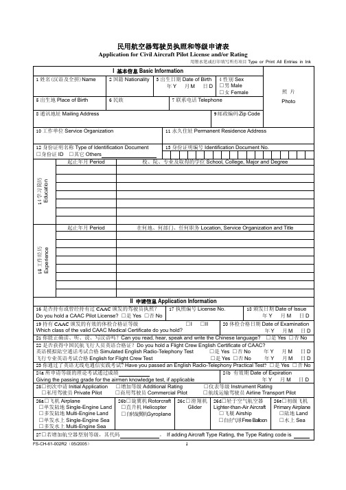
27□若增加航空器型别等级,其代码
。 If adding Aircraft Type Rating, the Type Rating code is
FS-CH-61-002R2(05/2005)
1
III 驾驶员飞行时间记录(阴影区域不填)Record of Pilot Time (Do not write in the shaded areas.)
Instrument
夜间带飞 时间 Night
Instruction
Received
夜间起落 次数Night
Take-off/
Landings
机长 夜间时间
Night PIC
时间单位:小时 Time: Hours
机长夜间 起落次数
Night Take-off/
Landing PIC
备注 Remark
FS-CH-61-002R2(05/2005)
IV 基于下列哪一项目申请执照和等级 License or Rating Applied for on Basis of
28 飞行训练学校名称 Name of Flight Training Unit
□A 毕业于按 61 部 批准的训练课程
Graduate of Approved CCAR-61 Training Course
26b□旋翼机 Rotorcraft □直升机 Helicopter □自转旋翼机Gyroplane
26c□滑翔机 Glider
26d□轻于空气航空器
Lighter-than-Air Aircraft □飞艇 Airship □自由气球Free Balloon
26e□初级飞机
Primary Airplane □陆地 Land □水上 Sea
UnitedHealthcare Community Plan 2021R0006A.LA 赔偿政策

Supply Policy, Professional for LouisianaIMPORTANT NOTE ABOUT THIS REIMBURSEMENT POLICYYou are responsible for submission of accurate claims. This reimbursement policy is intended to ensure that you are reimbursed based on the code or codes that correctly describe the health care services provided. UnitedHealthcare Community Plan reimbursement policies uses Current Procedural Terminology (CPT®*), Centers for Medicare and MedicaidServices (CMS) or other coding guidelines. References to CPT or other sources are for definitional purposes only and do not imply any right to reimbursement. This reimbursement policy applies to all health care services billed on CMS 1500 forms and, when specified, to those billed on UB04 forms. Coding methodology, industry-standard reimbursement logic, regulatory requirements, benefits design and other factors are considered in developing reimbursement policy.This information is intended to serve only as a general reference resource regarding UnitedHealthcare Community Plan’s reimbursement policy for the services described and is not intended to address every aspect of a reimbursement situation.Accordingly, UnitedHealthcare Community Plan may use reasonable discretion in interpreting and applying this policy to health care services provided in a particular case. Further, the policy does not address all issues related to reimbursement for health care services provided to UnitedHealthcare Community Plan enrollees. Other factors affecting reimbursement supplement, modify or, in some cases, supersede this policy. These factors include, but are not limited to: federal &/or state regulatory requirements, the physician or other provider contracts, the enrollee’s benefit coverage documents, and/or other reimbursement, medical or drug policies. Finally, this policy may not be implemented exactly the same way on the differentelectronic claims processing systems used by UnitedHealthcare Community Plan due to programming or other constraints; however, UnitedHealthcare Community Plan strives to minimize these variations.UnitedHealthcare Community Plan may modify this reimbursement policy at any time by publishing a new version of the policy on this Website. However, the information presented in this policy is accurate and current as of the date of publication. *CPT Copyright American Medical Association. All rights reserved. CPT® is a registered trademark of the American Medical Association.ApplicationThis reimbursement policy applies to UnitedHealthcare Community Plan Medicaid Product.This reimbursement policy applies to services reported using the 1500 Health Insurance Claim Form (a/k/a CMS-1500)or its electronic equivalent or its successor form. With the exception of Home Health Care and Durable Medical Equipment (DME), Orthotics and Prosthetic providers billing in place of service 12, this policy applies to all productsand all network and non-network physicians and other qualified health care professionals, including, but not limited to, non-network authorized and percent of charge contract physicians and other qualified health care professionals.PolicyOverviewThis policy describes the reimbursement methodology for Healthcare Common Procedure Coding System (HCPCS) codes representing supplies, drugs and other items based on the Place of Service (POS) submitted and Centers for Medicare and Medicaid Services (CMS). The website containing the POS code set can be accessed via this link:CMS POS Code Set.This policy does not apply to Home Health Care and DME providers reporting in a place of service 12 (home). Reimbursement GuidelinesSupply Reimbursement in a Physician’s or Other Qualified Healthcare Professional’s OfficeCertain HCPCS supply codes are not separately reimbursable as the cost of supplies is incorporated into the Evaluation and Management (E/M) service or procedure code. UnitedHealthcare Community Plan will not separately reimburse the HCPCS supply codes when those supplies are provided on the same day as an E/M service and/or procedure performed in a nonfacility place of service by a physician or other qualified health care professional.Supply Policy Code ListCasting and Splint SuppliesHCPCS codes A4570, A4580, and A4590 which were previously used for billing of splints and casts are invalid for Medicare use effective July 1, 2001, and new temporary Q codes were established to reimburse physicians and other practitioners for the supplies used in creating casts. Consistent with CMS, UnitedHealthcare Community Plan does not reimburse HCPCS codes A4570, A4580, and A4590 for casting and splint supplies. Physicians and other qualified health care professionals should the temporary Q codes (Q4001-Q4051) for reimbursement of casting and splint supplies.For the purposes of this policy, a nonfacility place of service is considered POS 1, 3, 4, 9, 11, 12, 13, 14, 15, 16, 17, 20, 33, 49, 50, 54, 55, 57, 60, 62, 65, 71, 72, 81 and 99.Implantable Tissue MarkersCMS clarifies that implantable tissue markers (HCPCS code A4648) and implantable radiation dosimeters (HCPCS code A4650) are separately billable and payable when used in conjunction with CPT codes 19499, 32553, 49411 or 55876 on a claim for physician services. Consistent with CMS, UnitedHealthcare Community Plan will allow separate reimbursement for HCPCS codes A4648 and A4650 when billed on the same date of service with either CPT codes 19499, 32553, 49411 or 55876. If A4648 and A4650 are reported in a facility setting or without CPT codes 19499, 32553, 49411, or 55876 they are not separately reimbursable.Reimbursement for Supplies, DME, Orthotics, Prosthetics, Biologicals, and Drugs Reported with Facility Places of Service 19, 21, 22, 23 and 24CMS follows a Prospective Payment System (PPS) where Medicare payment is based on a predetermined, fixed amount for inpatient or outpatient facility services. With these fixed rates all costs associated with supplies, DME, orthotics, prosthetics, biologicals and drugs are deemed included in the global payment to the facility and are not considered separately reimbursable when reported on a CMS-1500 claim form by a physician or other qualified healthcare professional.Consistent with CMS, UnitedHealthcare will not allow separate reimbursement for specific HCPCS supplies, DME, orthotics, prosthetics, biologicals, and drugs when submitted on a CMS-1500 claim form by any physician or other qualified health care professional in the following facility POS: 19, 21, 22, 23, and 24. The UnitedHealthcare Supply DME Codes in a Facility Setting and Supply Facility J-Code Denial Code list contains the codes that are not separately reimbursable in a facility place of service.Supply Facility J-Code Denial Code ListSupply DME Codes in a Facility SettingFor the purposes of this policy, a facility place of service is considered POS 19, 21, 22, 23, and 24.Durable Medical Equipment, Orthotics, Prosthetics, and Related Supplies Reported with Facility Places of Service 31 and 32In alignment with the CMS PPS reimbursement methodology, UnitedHealthcare considers payment for certain DME, orthotics, prosthetics and related supply items on the CMS Durable Medical Equipment, Prosthetics, Orthotics and Supplies (DMEPOS) fee schedule to be included in the payment to a skilled nursing facility (POS 31) and nursing facility (POS 32) and not reimbursed separately when reported by a physician or other qualified health care professional on a CMS-1500 claim form.Supply DME Codes in a Skilled Nursing FacilityFor the purposes of this policy, skilled nursing facility and nursing facility places of service are considered POS 31 and 32.Supply Code 99070For reimbursement of covered medical and surgical supplies, an appropriate Level II HCPCS code must be submitted. The non-specific CPT code 99070 (supplies and materials, except spectacles, provided by the physician or otherqualified health care professional over and above those usually included with the office visit or other services rendered [list drugs, trays, supplies, or materials provided]) is not reimbursable in any setting.State ExceptionsLouisiana Louisiana allows codes J7607 to be billed in POS 21 and allows code V2632 in POS19, 21, 21 22, 23 and 24.Louisiana allows code L8614 to be billed in POS 22 and allows codes A4570 andA4590 to be billed for cast/splint supplies.DefinitionsProspective Payment System A Prospective Payment System (PPS) is a method of reimbursement in which Medicare payment is made based on a predetermined, fixed amount. The payment amount for a particular service is derived based on the classification system of that service (for example, diagnosis-related groups for inpatient hospital services). CMS uses separate PPSs for reimbursement to acute inpatient hospitals, home health agencies, hospice, hospital outpatient, inpatient psychiatric facilities, inpatient rehabilitation facilities, long-term care hospitals, and skilled nursing facilities.Questions and Answers1 Q: If a member obtains medical supplies such as blood glucose test strips or lancets from a medical supply company, what place of service should the medical supply company report?A: Since the items are for home use, the medical supply company should report with a CMS Place of Service code 12 (Home). Reporting any other place of service code than 12 would be inappropriate when the items are dispensed for home use.Attachments: Please right-click on the icon to open the fileUnitedHealthcare Community Plan NON REIMBURSABLE Supply Codes List A List of HCPCS supply codes that are not separately reimbursable in an office, nonfacility or facility place of service.UnitedHealthcare Community Plan Facility J-Codes Denial Codes List A list of HCPCS drug codes not separately reimbursable in POS 19, 21, 22, 23 and 24.UnitedHealthcare Community Plan Supply DME Codes in a Facility Setting A list of DME codes for purchase only not separately reimbursable in POS 19, 21, 22, 23 or 24.Attachments: Please right-click on the icon to open the fileUnitedHealthcare Community Plan Supply DME Codes in a Skilled Nursing Facility A list of DME, Orthotics, Prosthetics, and related supplies not separately reimbursable in POS 31 or 32.ResourcesIndividual state Medicaid regulations, manuals & fee schedulesAmerican Medical Association, Current Procedural Terminology ( CPT® ) and associated publications and services Centers for Medicare and Medicaid Services, CMS Manual System and other CMS publications and services Centers for Medicare and Medicaid Services, Healthcare Common Procedure Coding System, HCPCS Release and Code SetsHistory2/15/2021 Removed reference to other state exceptions9/24/2020 State Exceptions section: Added Louisiana7/7/2019- 6/30/2019 Attachments section: Updated the UnitedHealthcare Community Plan Supply DME Codes in a Facility Setting (7/7/2019), the UnitedHealthcare Community Plan NON REIMBURSABLE Supply Codes List (6/30/2019) and the UnitedHealthcare Community Plan Facility J-Codes Denial Codes List (6/30/2019)6/16/2019 State Exceptions section: Added Washington5/19/2019 State Exceptions section: Added Florida and updated Ohio3/31/2019 Policy Version ChangeSupply Reimbursement in a Physician’s or Other Qualified Health Care Professional’s Officeand Other Nonfacility Places of Service Section: Verbiage updatedDefinitions Section: Updated1/13/2019 Attachments section: Updated the UnitedHealthcare Community Plan NON REIMBURSABLE Supply Codes List, UnitedHealthcare Community Plan Facility J-Codes Denial Codes List,UnitedHealthcare Community Plan Supply DME Codes in a Facility Setting, andUnitedHealthcare Community Plan Supply DME Codes in a Skilled Nursing Facility1/1/2019 Policy Version ChangeAttachments section: Updated the UnitedHealthcare Community Plan NON REIMBURSABLESupply Codes ListHistory section: Entries prior to 1/1/2017 archived12/9/2018 Attachments section: Updated the UnitedHealthcare Community Plan NON REIMBURSABLE Supply Codes List and description12/2/2018 Policy Approval and Policy Version Change:Updates: Application, Overview, Supply Reimbursement in a Physician’s or Other QualifiedHealth Care Professional’s Office and Other Nonfacility Places of Service, Casting and SplintSupplies, Reimbursement for Supplies, Purchased Durable Medical Equipment (DME),Orthotics, Prosthetics, Biologicals, and Drugs submitted with a J Code Reported with FacilityPlaces of Service 19, 21, 22, 23 and 24, Definitions and Q&A sectionsRemoved: Bundling HCPCS Code L8680 with CPT Code 63650 sectionAttachments section: Updated the UnitedHealthcare Community Plan NON REIMBURSABLESupply Codes List, changed the UnitedHealthcare Community Plan Supply DME Codes in aFacility Setting and removed the UnitedHealthcare Community Plan Supply DME Codes in anAmbulatory Surgical Center.10/7/2018 - 12/1/2018 Attachments section: Updated the Supply DME Codes in a Facility Setting and the Supply DME Codes in an Ambulatory Surgical Center9/16/2018 Added the word “Professional” to the policy titleApplication section: Removed the verbiage and link for the provider website6/3/2018 Attachments section: Updated the UnitedHealthcare Community Plan Supply DME Codes in a Facility Setting, the UnitedHealthcare Community Plan Supply DME Codes in an AmbulatorySurgical Center and the UnitedHealthcare Community Plan Supply DME Codes in a SkilledNursing Facility.State Exceptions section: Updated Virginia5/20/2018 Attachments section: Updated the UnitedHealthcare Community Plan Facility J-Codes Denial Codes List.5/7/2018 State Exceptions section: Updated Nebraska adding the language: Per State Regulations, code 99070 is reimbursable with certain considerations. Please see the C&S NE Unlistedreimbursement policy.3/27/2018 State Exceptions section: Updated Wisconsin adding the language: Wisconsin state regulation considers POS 19 as non-facility place of service.1/1/2018 Policy Version ChangePolicy section: Removed the language “B undling HCPCS Code L8680 with CPT Code 63650”and“To further align with CMS, the UnitedHealthcare Community Plan Medicare Supply Policywill deny HCPCS code L8680 (Implantable neurostimulator electrode), when billed with CPTcode 63650 (Percutaneous implantation of neurostimulator electrode array, epidural) in an officeor nonfacility place of service, effective for dates of service 5/1/2016 and after”.Attachments section: UnitedHealthcare Community Plan Facility J-Codes Denial Codes Listupdated and UnitedHealthcare Community Plan Supply DME Codes in a Skilled Nursing Facilityupdated11/19/2017 Annual Approval Date: Updated11/12/2017 State Exceptions section: Updated Ohio adding the language: The state of Ohio allows HCPCS E0465 and E0466 to be paid in POS 31 & 32. Updated Louisiana adding the language: A4570and to the statement “Louisiana allows code L8614 to be billed in POS 22 and allows A4590 tobe billed for cast/splint supplies”.9/17/2017 State Exceptions section: Removed deleted code J73028/20/2017 State Exceptions section: J codes for Arizona (J7297, J7298, J7300, J7301 and J7307) Kansa (J7298, J7306 and J7307) Louisiana (J7297, J7298, J7300 and J7301) Mississippi (J7300,J7301, J7306, and J7307) and Washington (J7300, J7301 andJ7307) were removedAttachment section: UnitedHealthcare Community Plan Facility J-Codes Denial Codes Listupdated7/21/2017 State Exceptions section: Updated language for Virginia regarding code 990707/14/2017 Application section: Removed UnitedHealthcare Community Plan Medicare products asapplying to this policy. Added location for UnitedHealthcare Community Plan Medicarereimbursement policies7/3/2017 State Exceptions section: Removed language regarding cast/splint supplies for Iowa.5/21/2017 State Exceptions section: Updated language regarding cast supplies for Iowa and Louisiana.Attachment Section: Updated the UnitedHealthcare Community Plan Non Reimbursable SupplyCodes List. Added the Nebraska Non Reimbursable Supply Codes in POS 31 and 32 List.3/12/2017 Policy Verbiage Change: Reimbursement Guidelines Section updated to add Bundling HCPCS Code L8680 with CPT Code 63650 verbiage for Community Plan Medicare2/19/2017 State Exceptions section: Updated, Texas allows codes J2182, J2786, J7175, J7179, J7202, J7207 and J7209 to be billed in POS 19 and 22.2/12/2017 State Exceptions section: Updated the exception for Arizona LTC, codes E0194, E0304 and E0635 is payable in a Nursing Facility POS 31 and 32 and updated exception for Kansas, addedcode J7298 to POS 19 and 22.1/1/2017 Annual Version ChangeAttachments section: NON REIMBURSABLE Supply Codes List, Facility J-Codes Denial CodesList, Supply DME Codes in a Facility Setting, Supply DME Codes in a Skilled Nursing FacilityHistory Section: Entries prior to 1/1/2015 archived1/6/2006 Policy implemented by UnitedHealthcare Community PlanBack To Top。
s1r72u16 技术参考手册(s1r72u16 technical manual)

S1R72U16 Technical ManualNOTICENo part of this material may be reproduced or duplicated in any form or by any means without the written permission of Seiko Epson. Seiko Epson reserves the right to make changes to this material without notice. Seiko Epson does not assume any liability of any kind arising out of any inaccuracies contained in this material or due to its application or use in any product or circuit and, further, there is no representation that this material is applicable to products requiring high level reliability, such as, medical products. Moreover, no license to any intellectual property rights is granted by implication or otherwise, and there is no representation or warranty that anything made in accordance with this material will be free from any patent or copyright infringement of a third party. This material or portions thereof may contain technology or the subject relating to strategic products under the control of the Foreign Exchange and Foreign Trade Law of Japan and may require an export license from the Ministry of Economy, Trade and Industry or other approval from another government agency.All other product names mentioned herein are trademarks and/or registered trademarks of their respective companies.©SEIKO EPSON CORPORATION 2008, All rights reserved.ScopeThis document applies to the S1R72U16 IDE device - USB 2.0 host bridge LSI.Table of Contents1. Terminology (1)2. Functions (2)2.1Mode Settings (2)2.1.1Command System Setting (2)2.1.2Device Count Setting (2)2.1.3Interface Setting (3)2.2Internal Status Notification (3)2.3USB Device Connection Configuration (3)2.3.1LUN Treatment (5)2.4Operation Specifications for Resetting (6)2.5Commands Issued Independently to Storage Devices (7)2.5.1Commands Issued to Obtain Storage Device Information (7)2.5.2Commands Issued to Obtain Media Information (7)2.6Power Management (8)2.6.1USB Device SUSPEND/RESUME (8)2.6.2Sleep/Wakeup (8)2.6.3Storage Devices that do not Support RESUME (9)2.7IDE Function Specifications (9)2.7.1Operation Specifications for Initialization (9)2.7.2Supported Command List (11)2.7.2.1ATA Mode (11)2.7.2.2ATAPI Mode (13)2.7.3Information Specifications Returned for Each Command (16)2.7.3.1IDENTIFY DEVICE Data (16)2.7.3.2IDENTIFY PACKET DEVICE Data (19)2.7.3.3INQUIRY Data (20)2.7.4Processing Unsupported Commands (21)2.7.4.1Vendor Commands (21)2.7.5Operation Specifications for Error Occurrence (23)2.7.5.1When Storage Device Repeatedly Returns NAK (23)2.7.5.2Storage Device Connection Processing (23)2.7.5.3When Controlling a Storage Device (24)2.7.6Connection/Disconnection Specifications (26)2.7.6.1Pins Used for Connection/Disconnection (26)2.7.6.1.1XCD0 Pin (26)2.7.6.1.2XCD1 Pin (26)2.7.6.1.3XChgInt Pin (27)2.7.6.1.4ATA Task File Register Status Register Bit1 (29)2.7.6.2Procedure for Using Connect/Disconnect Pins (29)2.7.6.3Connection/Disconnection Pins Operation Specifications (30)2.7.6.3.1Basic Operation when Storage Device is Connected or Disconnected (30)2.7.6.3.2Operations on Detecting System Reset or Hardware Reset (31)2.7.6.3.3Connection/Disconnection Operations when XChgInt Pin is Low (32)2.7.6.3.4Connection/Disconnection Operations in Sleep State (34)2.7.7Download Function (35)2.8USB Function Specifications (37)2.8.1Operation Overview (37)2.8.2USB Device Detection (38)2.8.3Storage Device Control (40)2.8.4TPL (41)2.8.5NSF (42)2.8.5.1Unsupported Device (42)2.8.5.2Too Many Devices (43)2.8.5.3Too Many Hubs (43)2.8.5.4VBUS Over Current (43)2.9Development Support Functions (44)2.9.1History Display Function (44)2.9.2USB Logo Certification Support Function (44)3. Registers (45)Appendix A: ATA to ATAPI Conversion Specifications (46)1. Terminology1. TerminologyMain CPU The main CPU of the user’s system.FS Full-speed mode in the USB standard. Theoretical maximum transfer rateis 12 Mbps.HS High-speed mode in the USB standard. Theoretical maximum transfer rateis 480 Mbps.Mass Storage Class Mass storage class in the USB standardHub Class Hub class in the USB standardBulk Only Transport Protocol for issuing storage commands using bulk transfer only asstipulated for mass storage classCBI Transport Protocol for issuing storage commands using control, bulk, or interrupttransfer as stipulated for mass storage classEmbedded Host Compliance USB 2.0 logo certification for embedded hostsTPL Target peripheral listLUN Logical unit numberNSF No silent failuresSUSPEND USB device sleep stateRESUME USB device wakeupPort reset Resetting the port to which the storage device is connectedMass storage reset Resetting of the storage deviceCBW Command block wrapperCSW Command status wrapper2. Functions2. FunctionsThis LSI is an IDE device - USB 2.0 host bridge that features three different mode settings for command system, number of connected devices, and interface, to suit specific systems. For detailed information on individual modes, see “2.1 Mode Settings”.The device complies with the following standards in IDE mode.•AT Attachment with Packet Interface - 4, 5, 6 (ATA/ATAPI - 4, 5, 6)•Multi-Media Commands - 5 (MMC - 5) [CD/DVD support]•INF - 8070i, 8090i [MO support]•SFF - 8080 [CD support]•Information technology - SCSI/ATA Translation (SAT) [16 byte command is unsupported]CF+ and Compact Flash Specification Revision 3.0 I/O mode can be applied in CPU mode. However, this LSI has no CIS/CCR registers or attribute memory and does not meet CF standards.2.1 Mode SettingsThe LSI operating mode is set by the pins shown in Table 2.1.Do not change the setting pins after switching on the power.Table 2.1 Mode setting listType Pin Pin setting and modeCommand system PORT00(ATAxATAPI)High: ATA mode Low: ATAPI modeDevice count PORT01(2x1) High: two-device mode Low: one-device modeInterface PORT02(CPUxIDE) High: CPU mode Low: IDE mode2.1.1 Command System SettingThis specifies the command system for the main CPU controlling this LSI. Set to the modecorresponding to the driver installed in the main CPU. See “2.7.2 Supported Command List” fordetailed information on commands available in each mode.Optical disk devices like CD, DVD, and MO drives cannot be controlled in ATA mode and will beignored if connected. Specify ATAPI mode to use optical disk devices.The master and slave will use the same command system if the device count setting specifiestwo-device mode.2.1.2 Device Count SettingThis specifies the number of storage devices connected to the main CPU via this LSI. Set to two-device mode when controlling two devices (master snd slave) using the LSI. Set to one-device mode whencontrolling a single device; in this case, the CSEL signal shall be used as defined in the IDE standard.The CSEL pin on this LSI should be set to “Master (=Low)” in two-device mode.2. FunctionsSetting2.1.3 InterfaceThis specifies the connection interface between the main CPU and this LSI. Set to IDE mode whenconnecting the LSI to the main CPU IDE bus; set to CPU mode when connecting to the CPU bus.IDE mode enables use of PIO, Multi Word DMA, and Ultra DMA. PIO supports modes 0 to 4 (16.6MB/s); Multi Word DMA supports modes 0 to 2 (16.6 MB/s); and Ultra DMA supports 0 to 5 (100MB/s).CPU mode enables use of PIO and DMA.2.2 Internal Status NotificationThe GPO pins indicates the LSI's internal status. The main CPU can receive the LSI's internal status by using these.The PLL_Locked pin (port 13) indicates the LSI has started up without problems. It indicates “High” once the PLL begins oscillating when power is turned on and remains at “High” until power is turned off.The connection pins (ports 10 to 12) indicate storage device connection/disconnection status and changes.For detailed information on connect and disconnect operations, see “2.7.6 Connection/DisconnectionSpecifications”.For detailed information on the NSF notification pins (ports 14 to 17) used for USB logo certification, see “2.8.5 NSF”.2.3 USB Device Connection ConfigurationAn overview of storage device connections is given below. For detailed information on supported USB devices, see “2.8 USB Function Specifications”.Up to two storage devices can be connected. The third or subsequent storage devices connected will be ignored. The first of the two storage devices detected will be assigned as a master device; the secondstorage device detected will be assigned as a slave device.Up to three USB hubs can be connected. Any additional USB hubs or storage devices connected to such additional USB hubs will be ignored.Fig. 2.1 Basic configuration2. FunctionsFig. 2.2 Maximum configuration (for USB memory including hub function)Fig. 2.3 Minimum configurationFig. 2.4 Configuration exceeding device limits (storage devices)Fig. 2.5 Configuration exceeding device limits (USB hub)Treatment2.3.1 LUNOne LUN is detected as a single storage device. If a single storage device partitioned into LUN0 andLUN1 will be detected as two storage devices, no additional storage devices will be detected due to the limit of two storage devices.Figures 2.6 to 2.8 show the connection examples.Fig. 2.6 LUN treatment in basic configurationFig. 2.7 One storage device divided into two LUNs2.4 Operation Specifications for ResettingThis LSI supports ATA/ATAPI standard resetting (Hardware Reset, SRST, and DEVICE RESETcommand) and resets USB devices if the conditions described below are met. This means the main CPU has access to ATA/ATAPI resetting without considering USB standard resetting operations.As reference, Table 2.2 shows the correspondence between ATA/ATAPI and USB standard resetting. And conditions for issuing USB standard resetting.Table 2.2 Correspondence between ATA/ATAPI and USB standard resettingATA/ATAPI standardreset USB standardresetUSB standard reset issuing conditions(issue if any are satisfied) (*2)Hardware Reset Port reset(businitialization)(*1)•Command is being executed (Status register BSY bit or DRQ bit is 1).•During the interval between return of error status to the main CPUafter the occurrence of an error in USB protocol and reception ofsubsequent command.•During the interval between return of error status to the main CPUwhen no response is received from the USB device and receptionof subsequent command.•Storage device is not connected.SRSTDEVICE RESET command (ATAPI mode only) Mass storagereset(individualdeviceinitialization)•Command is being executed (Status register BSY bit or DRQ bit is 1).•During the interval between return of error status to the main CPUafter the occurrence of an error in USB protocol and reception ofsubsequent command.•During the interval between return of error status to the main CPUwhen no response is received from the USB device and receptionof subsequent command.*1 Since the port reset cause the USB devices disconnect temporarily, master and slave assignments for storage devices may change when a Hardware Reset is executed with multiple connected storage devices.*2 When the storage device is normal state and the command is not executed, then the reset is not issued.For detailed information on USB protocol errors, see “2.7.5.3 When Controlling a Storage Device”.The LSI status is as shown below after resetting. The status after a Hardware Reset is the same as after power on.After a SRST or DEVICE RESET command, the data set by the main CPU is retained.• All resets¾Functions set by the DOWNLOAD MICROCODE command are retained.¾The XCD0/XCD1 pins retain the status existing before resetting.¾Sleep is reset (complies with ATA/ATAPI standard).• Hardware Reset¾Initializes XChgInt pin and sets to High.¾Initializes data set by commands from main CPU (complies with ATA/ATAPI standard).•SRST/DEVICE RESET command¾XChgInt pin retains status existing before resetting.¾Retains data set by commands from main CPU (complies with ATA/ATAPI standard).2.5 Commands Issued Independently to Storage DevicesThis LSI issues commands independently to storage devices under certain conditions, regardless of main CPU command issuing. The main CPU need not be aware of this command issuing.2.5.1 Commands Issued to Obtain Storage Device InformationThe LSI issues the commands shown in Table 2.3 to obtain storage device information when conditions detected indicate that the storage device may have been changed.Table 2.3 Commands for obtaining storage device informationCommand Issuing conditionsINQUIRY •When Hardware Reset, SRST, or DEVICE RESET command is detected (e.g., when power is turned on)•When storage device connection is detected•When an IDENTIFY DEVICE or IDENTIFY PACKET DEVICE command is detected2.5.2 Commands Issued to Obtain Media InformationThe LSI issues the commands shown in Table 2.4 in sequence to obtain media information in thefollowing situations in which the storage device or media may have been changed and the issuingconditions are also satisfied.•After detecting Hardware Reset, SRST, or DEVICE RESET command (e.g., when power is turned on)•After detecting storage device connection•After detecting a media change error from a storage deviceTable 2.4 Commands obtaining media informationCommand Issuing conditionsTEST UNIT READY When any of the following commands is received first under the conditions described above•When a command other than INQUIRY or REQUEST SENSE is received in ATAPI mode•When a command (command returning MC or NM error) is received to access the media in ATA modeREAD DISC STRUCTURE When the TEST UNIT READY command above ends normally*Issued only in ATAPI mode when the storage device is a CD or DVDREAD CAPACITY •When the READ DISC STUCTURE command above is issued and ends normally •When the READ DISC STUCTURE command above is not issued and the TEST UNIT READY command ends normally*READ CAPACITY is issued before READ DISC STRUCTURE, when media change was notified from the storage device by TEST UNIT READY. (It was added in S1R72U16XXXE200.)2.6 Power ManagementThe main CPU can manage USB device power via procedures that comply with the ATA/ATAPI standard.This section describes power-conservation functions (SUSPEND/RESUME) for the LSI and connected storage devices.2.6.1 USB Device SUSPEND/RESUMEThe main CPU can switch storage devices to power-conservation mode using the SLEEP commandand resume by resetting. No special processing is needed at the main CPU other than the ATA/ATAPI standard.This LSI switches USB devices to SUSPEND state on receiving a SLEEP command. In two-devicemode, all USB devices switch to SUSPEND when a SLEEP command for both master and slave isreceived.The LSI switches all USB devices to RESUME on receiving any of the reset commands described in“2.6.2 Sleep/Wakeup”. In two-device mode, the DEVICE RESET command switches all USB devices to RESUME when a command for either a master or slave is received.* The LSI switches all USB devices to RESUME on receiving a single DEVICE RESET command.Individual DEVICE RESET commands should be issued for storage devices (master/slave)controlled initially.2.6.2 Sleep/WakeupThe LSI automatically switches to Sleep state when all storage devices detected are in SUSPEND state.In two-device mode, the LSI does not switch to Sleep state unless SLEEP commands are issued forboth the master and slave, even if only one storage device is actually present.The LSI switches to Wakeup when any of the following resets are detected in Sleep state. No specialprocessing is needed by the main CPU to switch the LSI to Sleep or Wakeup states.• Hardware Reset• SRST•DEVICE RESET command (command results in an error in ATA mode)2.6.3 Storage Devices that do not Support RESUMESome storage devices do not support RESUME and may operate as shown below after the RESUMEcommand.•No response to issued command.•Receives command but subsequently continues to return NAK.If the storage device does not respond to the command issued, the LSI indicates that the storage device is not connected to the main CPU. If the storage device issues an NAK response, the reset described in “2.6.2 Sleep/Wakeup” will not terminate and persists in a Busy state (Status register BSY bit is 1).Under these conditions, the main CPU should issue a Hardware Reset. The LSI initializes andreconnects the storage devices.2.7 IDE Function SpecificationsThe main CPU is capable of controlling the LSI and storage devices connected to the LSI as devicescomplying with the ATA/ATAPI standard. This section describes detailed information on theATA/ATAPI commands supported by the LSI, data returned to the main CPU, andconnection/disconnection methods.Observe the following precautions when using the LSI.•Use ATAPI mode when controlling optical disk devices like CD, DVD, and MO drives.•Set the CSEL pin to Master (= Low) when using the LSI in two-device mode.•The maximum data size that can be transferred with a single command is 800000h bytes for -Ultra DMA transfer in the DATA-OUT (Write) direction.•Disconnection/connection changes occur as storage devices are temporarily disconnected while processing the DOWNLOAD MICROCODE command.Specifications for Initialization2.7.1 OperationThe LSI performs the following processing during initialization (in Busy state). No special processing is needed by the main CPU except for initialization processing in accordance with the ATA/ATAPIstandard.•The DASP signal is asserted in two-device mode or for the slave in one-device mode.•The storage device information is obtained if storage devices are connected.For detailed information on initialization processing for the connect/disconnect pins, see “2.7.6.3.2Operations on Detecting System Reset or Hardware Reset”.The LSI resets the Busy state once the storage device connection processing is complete, notifying the main CPU that the storage device is connected. Control of the storage device by the main CPU begins once this initialization is complete.Fig. 2.9 DASP/PDIAG initialization specificationsFig. 2.10 XCD0/XCD1 initialization specifications2.7.2 Supported Command ListThe main CPU is capable of controlling the LSI using ATA/ATAPI commands. The commandssupported by the LSI are shown below.2.7.2.1 ATAModeTable 2.5 shows the supported ATA commands. The commands indicated in bold type areprocessed within the LSI and are not issued to storage devices. Shaded commands are issued tostorage devices converted to ATAPI commands.Table 2.5 Supported ATA command listTransfer method TransfersizeCode Command RemarksE5h CHECK POWER MODEEnds normally even if no storage device isconnected.90hEXECUTE DEVICEDIAGNOSTICEnds normally even if no storage device isconnected.E7h FLUSHCACHEEAh FLUSH CACHE EXTReturns normal completion status without takingany action.DAh GET MEDIA STATUSIssues TEST UNIT READY command and checksdevice status.E3h IDLEConverts to START/STOP UNIT command(Immed bit = 0, Start bit = 1)Ends normally even if no storage device isconnected.E1h IDLE IMMEDIATEConverts to START/STOP UNIT command(Immed bit = 1, Start bit = 1)Ends normally even if no storage device isconnected.91hINITIALIZE DEVICEPARAMETEREnds normally even if no storage device isconnected.00h NOP40hREAD VERIFYSECTOR(S)42hREAD VERIFYSECTOR(S) EXTIssues TEST UNIT READY command and checksdevice status.70h SEEK Converts to SEEK (10) command.EFh SETFEATURESEnds normally even if no storage device isconnected.C6h SET MULTIPLE MODEEnds normally even if no storage device isconnected.E6h SLEEPEnds normally even if no storage device isconnected.E2h STANDBYConverts to START/STOP UNIT command(Immed bit = 0, Start bit = 0)Ends normally even if no storage device isconnected.No data −E0h STANDBY IMMEDIATE Converts to START/STOP UNIT command (Immed bit = 1, Start bit = 0)Ends normally even if no storage device is connected.512ECh IDENTIFY DEVICE Returns data generated from information obtained using INQUIRY and READ CAPACITY commands.Ends normally even if no storage device is connected.C4h READ MULTIPLE 29h READ MULTIPLE EXT 20h READ SECTOR(S) PIO INSector count24h READ SECTOR(S) EXT Converts to READ (10) or READ (12) command.C5h WRITE MULTIPLE 39h WRITE MULTIPLE EXT 30hWRITE SECTOR(S) 34h WRITE SECTOR(S) EXT Converts to WRITE (10) or WRITE (12) command.PIO OUTSector count92hDOWNLOADMICROCODE Data is transmitted to this LSI, and the function is updated.Ends normally even if no storage device is connected.C8h READ DMA DMA IN Sector count 25h READ DMA EXT Converts to READ (10) or READ (12) command. CAh WRITE DMA DMA OUT Sector count35hWRITE DMA EXTConverts to WRITE (10) or WRITE (12) command.Table 2.6 Specially supported commands for backward compatibilityTransfer method Transfer sizeCode CommandRemarksNo data−10h RECALIBRATEReturns normal completion status without taking any action.Ends normally even if no storage device is connected.Table 2.7 Unsupported commands returning errorsTransfer method Transfer sizeCode Command RemarksNo data − 08h DEVICE RESET Returns error status.PIO IN 512A1hIDENTIFY PACKETDEVICEDoes not transfer data; returns error status.2.7.2.2 ATAPIModeTable 2.8 shows the supported ATA commands. Tables 2.9 and 2.10 show the supported ATAPIcommands. The commands indicated in bold type are processed within the LSI and are not issued tostorage devices. ATAPI commands are issued unchanged to the storage devices.Table 2.8 Supported ATA command listTransfer method TransfersizeCode Command RemarksE5h CHECK POWER MODEEnds normally even if no storage device isconnected.08h DEVICERESETUSB is reset if storage device is processingcommand.Ends normally even if no storage device isconnected.90hEXECUTE DEVICEDIAGNOSTICEnds normally even if no storage device isconnected.E1h IDLEIMMEDIATEEnds normally even if no storage device isconnected.00h NOP37h SETFEATURESEnds normally even if no storage device isconnected.E6h SLEEPEnds normally even if no storage device isconnected.No data −E0h STANDBYIMMEDIATE Ends normally even if no storage device is connected.PIO IN 512 A1hIDENTIFY PACKETDEVICEReturns data generated from information obtainedusing INQUIRY command.Ends normally even if no storage device isconnected.PIO OUT Sectorcount92hDOWNLOADMICROCODEData is transmitted to this LSI, and the function isupdated.Ends normally even if no storage device isconnected.−− A0hPACKETTable 2.9 Supported ATAPI command list (HDD, flash memory)Transfer methodTransfer sizeCode Command Remarks1EhPREVENT/ALLOW MEDIUM REMOVAL2Bh SEEK(10)1Bh START/STOP UNIT 00hTEST UNIT READY2Fh VERIFY(10)No data−2Eh WRITE AND VERIFY(10) 04h FORMAT UNIT12h INQUIRYEnds normally even if no storage device is connected. 5Ah MODE SENSE(10)25h READ CAPACITY 23hREAD FORMAT CAPACITYUnspecified03h REQUEST SENSEData which is in advance acquired by this command is returned. Ends normally even if no storage device is connected. 28h READ(10) PI/DISectorcountA8h READ(12)Unspecified 55hMODE SELECT(10)2Ah WRITE(10) PO/DOSector countAAh WRITE(12)Table 2.10 Supported ATAPI command list (CD, DVD, MO)Transfermethod Transfer sizeCode Command Remarks1EhPREVENT/ALLOW MEDIUM REMOVAL2Bh SEEK(10)1Bh START/STOP UNIT 00hTEST UNIT READY2Fh VERIFY(10)2Eh WRITE AND VERIFY(10) A1h BLANK5Bh CLOSE TRACK/SESSION 2Ch ERASE (10)A6h LOAD/UNLOAD MEDIUM 4Bh PAUSE/RESUME 45h PLAY AUDIO (10) A5h PLAY AUDIO (12) A7h PLAY AUDIO MSF 58h REPAIR TRACK 53h RESERVE TRACK BAh SCAN BBhSET CD SPEEDNo data−A7h SET READ AHEAD4Eh STOP PLAY/SCAN35h SYNCHRONIZE CACHE 04h FORMAT UNIT12h INQUIRYEnds normally even if no storagedevice is connected. 5Ah MODE SENSE(10) 25h READ CAPACITY 23hREAD FORMAT CAPACITIES03h REQUEST SENSE Data which is in advance acquired by this command is returned.Ends normally even if no storage device is connected. 46h GET CONFIGURATION4AhGET EVENT/STATUS NOTIFICATIONACh GET PERFORMANCE BDh MECHANISM STATUS 3Ch READ BUFFER 5Ch READ BUFFER CAPACITY 51h READ DISC INFORMATION ADhREAD DISC STRUCTURE44h READ HEADER 42h READ SUB-CHANNEL 43h READ TOC/PMA/ATIP 52h READ TRACK INFORMATION UnspecifiedA4h REPORT KEY 28h READ(10)A8h READ(12) BEh READ CD PI/DISectorcountB9h READ CD MSF 55h MODE SELECT(10)5Dh SEND CUE SHEET BFhSEND DISC STRUCTUREA2h SEND EVENT A3h SEND KEY 54hSEND OPC INFORMATIONB6h SET STREAMING Unspecified3Bh WRITE BUFFER2Ah WRITE(10) PO/DOSectorcountAAh WRITE(12)2.7.3 InformationSpecifications Returned for Each CommandThe main CPU can obtain information on the storage device connected to the LSI using the commands described here. The methods used to generate the information are described below.2.7.3.1 IDENTIFY DEVICE DataTable 2.11 shows the data returned by the IDENTIFY DEVICE command. The LSI incorporates theinformation obtained from the connected storage device into data returned to the main CPU.The values indicated in bold type are fixed. Values enclosed in bold frames are values generatedbased on information obtained from the storage device using the INQUIRY or READ CAPACITYcommands. The position of the generated values is indicated by “x”. The shaded areas indicatevalues replaced by the commands issued by the main CPU (colors indicate different commands).Thus, the values shown are default values.Table 2.11 IDENTIFY DEVICE dataWords Value Details0 0080h ATA removable1 xxxxh Total cylinder count (determined by storage device capacity: Max value is 3FFFh)Calculated from data obtained using READ CAPACITY command (*1) Returns 0000h when no device is connected.2 0000h3 0010h Total header count4 to5 0000h6 003Fh Sector count per track7 to 9 0000h10 to 12 xxxxh13 xxxxh14 to 19 2020h Serial numberS1R72U16XXXE100:word10~19 2020h fixedS1R72U16XXXE200:word10~12 3030h fixedword133030h(Master),3031h(Slave) word14~19 2020h fixed20 to 22 0000h23 to 26 xxxxh Firmware revisionSetting data generated from data obtained using INQUIRY command (*2) Returns “rev1.0” when no device is connected.27 to 46 xxxxh Model numberSetting data generated from data obtained using INQUIRY command (*3) Returns “____ S1R72U16” when no device is connected.47 8002h Maximum INTRQ assert sector size for READ/WRITE MULTIPLE command48 0000h49 0000111100000000b bit 11 = 1, bit 10 = 1: IORDY support and IORDY disable support bit 9 = 1: LBA supportbit 8 = 1: DMA support50 0100000000000000b51 0200h PIO Mode2 support52 0000h53 0000000000000111b Word 88, words 64 to 70, words 54 to 58 enable。
VigorACS 2 Quick Start Guide

V i g o r A C S2U n i f i e d M a n a g e m e n t S y s t e mManual Version: 1.0Software Version: V2.3.1Date: August 17, 2018Table of Contents1. Platform for Windows 7 or 10 (5)1.1 Installation for Java (5)1.2 Installation for MariaDB (9)1.3 Installation for VigorACS 2 (14)1.4 StartMySQL/MariaDB Databse (23)1.5 Start VigorACS (23)2. Platform for Linux (25)2.1 Installation for MariaDB, Java and VigorACS (25)2.2 Start MySQL/MariaDB Databse (31)2.3 Start VigorACS (31)2.4 Edit VigorACS IP (31)3. Registering VigorACS 2 (32)3.1 Registration for VigorACS via Windows Platform (32)4. Configuration on CPE Device (37)4.1 Set ACS URL on CPE (37)4.2 Invoke Remote Management for CPE (39)4.3 Enable WAN Connection on CPE (40)5. Troubleshooting (42)1.P l a t f o r m f o r W i n d o w s7o r10Please follow the procedure listed below to install VigorACS 2 completely. The installation for different platforms might be different.T o start up the VigorACS, the normal procedure is listed as follows:(I)Installation for Java(II)Installation for MariaDB(III)Installation for VigorACS 2(IV)Start MySQL/MariaDB Database.(V)Edit VigorACS IP.(VI)Start VigorACS.Info VigorACS 2 can be operated only by a host with 64-bit operation system.1.1I n s t a l l a t i o n f o r J a v a1.Install Java by clicking “java-1.8.0-openjdk-1.8.1.151-1.b12…” to execute the installation.2.The first page will be shown as follows. Click Next to get into next page.3.Then, check “I accept the terms…” and click the Next button.4.In this page, optional features will be listed for you to specify the destination folder forJAVA driver installation. Choose the one you need and click Next.5.In the following page, just click Install.6.Wait for a while to install the required features.7.When the following page appears, the installation is completed. Click Finish to exit theinstalling program.1.2I n s t a l l a t i o n f o r M a r i a D B1.Install MariaDB by clicking “mariadb-10.2.10-winx64” (based on your PC condition) it toexecute the installation.2.When the welcome screen appears, please click Next for next step.3.On this dialog box, check the box of “I accept the terms….” and click Next.4.Select the way for the features to be installed. Then click Next.5.If you want to configure password for MariaDB server, please check Modify password… andtype the password. It depends on your request. Otherwise, simply click Next.6.Modify the default instance properties if required. Then click Next.7.On this dialog box, click Next.8.On this dialog box, click Install.9.The installation program starts to install required files for MariaDB to your computer. Waitfor several seconds.10.After finishing the configuration, please click Finish to exit the wizard.1.3I n s t a l l a t i o n f o r V i g o r A C S2It is time to install VigorACS main program. Follow the steps below.1.Click Setup to run VigorACS 2 setup wizard.2.When the following dialog appears, choose Local Database / Remote Database and clickNext.3.Select the directory that MariaDB being installed (done in 1.2) and click Next4.In this dialog box, choose Rebuild Database (for rebuilding the VigorACS database) orUpgrade Database (for upgrading the database). For the first time using, please choose Rebuild Database. Then click Next.5.Click Next. If you have configured MySQL/MariaDB previously and specified password for it,you have to type the password in this page and then click Next.6.Set the maximum memory and minimum memory. Click Next.7.Setup ACS HTTP and HTTPS port, we'll suggest using others port instead of default 80 and443 port to prevent conflict.Info The port number defined here will be used for opening VigorACS later.8.Determine the home path and click Next. The default directory used by this program isC:\Users. You can modify it if you want and please make sure the length of directory is not over 100 characters, otherwise you might encounter problem of VigorACS in installation.9.Determine the destination folder and click Next. The default directory used by thisprogram is C:\Program Files\VigorACS. You can modify it if you want and please make sure the length of directory is not over 100 characters, otherwise you might encounter problem of VigorACS in installation.10.Determine the start menu folder and click Next. The default directory used by thisprogram is VigorACS. You can modify it if you want and please make sure the length of directory is not over 100 characters, otherwise you might encounter problem of VigorACS in installation.11.In this dialog, check the box of “Create a desktop shortcut” for your necessity. Click Next.12.Now, the program is ready to install necessary features and files to your computer. Pleaseclick Install to start.13.Please wait for a while to complete the installation.14.While installing, the following screen will appear to show that MariaDB has been activated.Please wait for next dialog appearing.15.Now the program has completed the installation of VigorACS 2. Click Finish to exit it.1.4S t a r t M y S Q L/M a r i a D B D a t a b s eAfter installing VigorACS, install program will register MySQL/MariaDB to Windows Service.MySQL /MariaDB will startup automatically after installing VigorACS or rebooting system.Normally, you don't need to worry about this step on Windows. But if you find any problems on VigorACS, you should check mysql/mariadb first. Please go to Windows Service check theMySQL/MariaDB Service starts or not.1.5S t a r t V i g o r A C S1.Login VigorACS. Use a web browser and type “localhost:portnumber”. Note that the portnumber must be the one defined for HTTP and HTTPS port while installing VigorACS. Forexample, if HTTPS is defined as 8011, then the URL will be “localhost:8011”.2.The login page of VigorACS will be shown as the following. Please type “root” as user nameand “admin123” as password and type the authentication code. Then click Login.3.For the first time to access into the web user interface, a warning message appears first.Please click the Change password button to change the default password for networksecurity. If not, click Cancel to access into the web user interface of VigorACS and changethe password later.4.After clicking Login, main screen of VigorACS 2 will be shown as below.2.P l a t f o r m f o r L i n u xT o start up the VigorACS under Linux, please execute"/usr/local/vigoracs/VigorACS/bin/vigoracs.sh" instruction. A list of menu items will be shown as follows.1.Start mysql/mariadb2.Shutdown mysql/mariadb3.Start VigorACS4.Shutdown VigorACS5.Edit bind IP of VigorACS Server (please key in IP or server name)6.Set the Max. and Min. memory value of running java (it will be valid after restartingVigorACS)7.View the Max. and Min. memory value of running java8.exit2.1I n s t a l l a t i o n f o r M a r i a D B,J a v a a n d V i g o r A C SFollow the steps listed below to install VigorACS under Linux:1.Login Linux with root or the root privilege.2.Download the ACS installation tar.bz2 package and extract it via below command:#bzip2 -cd VigorACS_Unix_Like_xxxxxx_xxxxx.tar.bz2 | tar xvf -or#tar -jxv -f VigorACS_Unix_Like_xxxxxx_xxxxx.tar.bz23.Decompress the setup packagesbzip2 -cd VigorACS_Unix_Like_xxxxxx_xxxxx.tar.bz2 |tar xvf –4.Change the permissions mode of install.sh and uninstall.sh.chmod 755 install.shchmod 755 uninstall.sh5.Execute ./install.sh installation file.Please make sure you have /usr/bin/sh first. If you don't have /usr/bin/sh, please enter the command:#ln -s /bin/sh /usr/bin/sh6.The system will ask to create vigoracs, enter “y” to proceed.7.Next, the system will ask you to install xfonts-base and fontconfig, just enter “y” toproceed.8.Next, please select the item number which you want to execute. Note that VigorACSsupports Linux OS. The program will detect the system you have in your computer.(1) Install mysql/mariadb(2) Change root password and security configuration of mysql/mariadb(3) Install or Upgrade java(4) Install VigorACS(5) Upgrade VigorACS(6) Redirect the database path of VigorACS to remote host (7) Exitinput select num:InfoIf your computer has installed MariaDB and java previously, ignore theinstallation of them. Otherwise, install all the required items (MariaDB, Java and VigorACS) for your system. Item number 5 is used to upgrade VigorACS, so it is not necessary for you to execute for the first time of installation.9. Input 1 to install MariaDB first. Notice that it will setup blank as default password. You canchange the password by using the following command.#/usr/local/mysql/bin/mysqladmin--defaults-file=/usr/local/mysql/f -u root password 'newpassword'InfoThe password configured by the command above will be effective onlywhen there is no password set for database root before.Follow the instructions on the screen to finish the MariaDB installation.ter, input 2 to change root password and security configuration of mysql/mariadb.Info The password set in this step is used for VigorACS 2 to login database.11.Input 3 to install Java.Follow the instructions on the screen to finish the Java installation.12.Input 4 to install VigorACS. It is suggested to use ACS customized MariaDB database. Whenasked to enter MariaDB password, press “Enter” if you haven’t changed the password via the command. Then, confirm that TR-069 database has been installed successfully.Wait and follow the instructions on the screen to finish the installation.13. Now, input 6 to redirect the database path of VigorACS to remote host. For remotedatabase, please execute such step on remote host.14. Input 7 to finish and exit the installation.Info 1 Step 13 is required for establishing remote database only . You can ignore it while building local database.Info 2T o prevent port conflicts, we'll suggest that using other ports for HTTP and HTTPS instead of default 80 and 443.2.2S t a r t M y S Q L/M a r i a D B D a t a b s eAfter installing VigorACS, mysql/mariadb daemon has started. You can to see it using "ps-ef|grep mysql" instruction. Use the menu item 1 / 2 to start / shutdown mysql/mariadb.2.3S t a r t V i g o r A C SAfter installing VigorACS, access “/usr/local/vigoracs/VigorACS/bin”, execute “./vigoracs.sh”.Select item 3 to start VigorACS.If you ever reboot the machine after installing VigorACS, just select item 1 to startmysql/mariadb first. Then, select item 3 to start VigorACS.2.4E d i t V i g o r A C S I PWhen starting the VigorACS at first time on Linux, startup program will ask you input Server IP or input Enter key by using the IP address of the host. Once you input the IP address, VigorACS will keep it on startway.txt. Next time, if you want to change it, you can select item 5 to editstartway.txt using vi editor.3. R e g i s t e r i n g V i g o r A C S 2For the first time to activate VigorACS 2, the system will ask you to register VigorACS 2 onto DrayT ek MyVigor server . Refer to the following sections to register VigorACS 2 on differentplatforms.Info 1 While installing VigorACS, install program will register MySQL/MariaDB toWindows Service. MySQL/MariaDB will startup automatically after installingVigorACS or rebooting system. Normally , you don't need to worry about this step on Windows. But if you find any problems on VigorACS, you should checkmysql/mariadb first. Please go to Windows Service check the MySQL/MariaDB Service starts or not.Info 2After installing VigorACS, the software will startup automatically . Normally ,you don't need to worry about this step on Windows. But, if you find any problem on VigorACS, you could shut down VigorACS and start VigorACS again. 3.1 R e g i s t r a t i o n f o r V i g o r A C S v i a W i n d o w s P l a t f o r mBelow shows the steps to register VigorACS 2:1. Login VigorACS. Use a web browser and type “localhost:portnumber”. Note that the portnumber must be the one defined for HTTP and HTTPS port while installing VigorACS. For example, if HTTPS is defined as 8011, then the URL will be “localhost:8011”.2. The login page of VigorACS will be shown as the following. Please type “root” as user nameand “admin123” as password and type the authentication code. Then click Login.Info“root” and “admin123” are default settings.3. A License Error dialog appears as follows. Simply click Active.4. A login page for MyVigor web site will be popped up automatically . Type your account (username) and password in this page. Then, click Login.InfoIf you do not have any account, simply click Create an account now to create a new one for using the service provided by MyVigor web site.5.MyVigor will verify and authenticate if the user account you typed is allowed to access intothe web site. If yes, the following screen will appear.6.Type a nickname for VigorACS and click Add.7.After clicking Add, you can see the following screen. Click OK.8.You will get a device information page as shown below. If you are the new user of VigorACS,you can get a free charge of 30-day service of VigorACS. Simply click the Trial button.9.From the following screen, check the box of “I have read and accept the above….” andclick Next.10.In the page below, click Register.11.When the VigorACS License Information page appears, the service is ready for you to use.Click Login to ACS to use VigorACS service.12.The login page will appear as follows. Type the default settings of User Name (root) andPassword (admin123) and type the authentication code. Then, click Login.13.Now, the main screen of VigorACS will be shown as follows.4.C o n f i g u r a t i o n o n C P E D e v i c e4.1S e t A C S U R L o n C P ET o manage CPEs through VigorACS, you have to set ACS URL on CPE first and set username and password for VigorACS.1.Connect one CPE (e.g., Vigor2862 series).2.Open a web browser (for example, IE, Mozilla Firefox or Netscape) on your computer andtype http://192.168.1.1.3.Please type username and password on the window. If you don’t know the correctusername and password, please consult your dealer to get them. In this section, we takethe figures displayed on Windows as examples.4.Go to System Maintenance -> TR-069.•Please set URL as the following and type username and password for ACS server,for the connected CPE with authentication:http://{IP address of VigorACS}:80/ACSServer/services/ACSServlet•Please set URL as the following, for the connected CPE without authentication: http://{IP address of VigorACS}:80/ACSServer/services/UnAuthACSServlet•Please set URL as the following, for the connected CPE with authentication and the data transmission between CPE and VigorACS 2 with encryption (SSL).https://{IP address of VigorACS}:443/ACSServer/services/ACSServlet•Please set URL as the following, for the connected CPE without authentication but the data transmission between CPE and VigorACS 2 with encryption (SSL)https://{IP address of VigorACS}:443/ACSServer/services/UnAuthACSServlet5.Fill Username and Password for VigorACS 2 Server for authentication. Please enter as thefollowing:Username: acsPassword: password6.For the username and password of CPE client, it is not necessary for you to type them.7.Click Enable for Periodic Inform Settings.4.2I n v o k e R e m o t e M a n a g e m e n t f o r C P EYou have to make sure that the CPE device you want to connect supports VigorACS 2 features.Please consult your dealer if you have no idea in it.1.Suppose WAN IP of CPE device has been setup successfully. And you can access into Internetwithout difficulty.2.Login the device (e.g., Vigor2862) by web.3.Go to System Maintenance>>Management.4.Check Allow management from the Internet to set management access control.4.3E n a b l e W A N C o n n e c t i o n o n C P EYou have to make sure the CPE device you want to connect has been configured properly and can access into Internet.1.Login the device (e.g., Vigor2862) by web.2.Open WAN>>Internet Access.3.Choose Static or Dynamic IP as Access Mode and click Details Page for WAN2.4.The following web page appears. Click Enable and Specify an IP address. Enter correctWAN IP address, subnet mask and gateway IP address for your CPE. Then click OK.VigorACS 2 Quick Start Guide41InfoReboot the CPE device and re-log into VigorACS 2. CPE which has registered to VigorACS 2 will be captured and displayed on the home page of VigorACS 2.VigorACS 2 Quick Start Guide42 5. T r o u b l e s h o o t i n gWhen you try to invoke VigorACS 2 and get the following error message, please locate the file of “server .log ” from C:/Program Files/VigorACS/server/default/log and send the file to yourdealer for further assistance.For Linux system, please locate the file of “server .log ” from/usr/local/vigoracs/VigorACS/server/default/log/ and send the file to your dealer for further assistance.。
Magnetic photonic crystals

Magnetic photonic crystals
I L Lyubchanskii1,4 , N N Dadoenkova1 , M I Lyubchanskii1 , E A Shapovalov2 and Th Rasing3
1 Donetsk Physical and Technical Institute of the National Academy of Sciences of Ukraine, 72, R. Luxemburg St., 83114 Donetsk, Ukraine 2 Department of Physics, Donetsk National University, 24, Universitetskaya St., 83055 Donetsk, Ukraine 3 NSRIM Institute, University of Nijmegen, 6525 ED, Nijmegen, The Netherlands
INSTITUTE OF PHYSICS PUBLISHING J. Phys. D: Appl. Phys. 36 (2003) R277–R287
JOURNAL OF PHYSICS D: APPLIED PHYSICS PII: S0022-3727(03)58197-9
TOPICAL REVIEW
0022-3727/03/180277+11$30.00
© 2003 IOP Publishing Ltd
Printed in the UK
Topical Rs a result, the light polarization properties undergo modifications. In this paper we present a short review of MPCs. The paper is organized as follows. In section 2 we discuss the MPCs in the microwave region. Section 3 is devoted to MPCs in the near infrared and visible regions. In section 4 we present the results on PBG effects in magnetic liquids and magnetic colloids. Magnetic films with regular domain structures such as MPCs are considered in section 5. Finally, nonlinear optical effects in MPCs are presented in section 6. A perspective on the use of magnetic materials as MPCs is given in section 7.
MPLAB Code Configurator v2.25 1 产品说明书
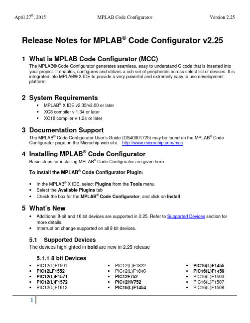
Release Notes for MPLAB® Code Configurator v2.251 What is MPLAB Code Configurator (MCC)The MPLAB®Code Configurator generates seamless, easy to understand C code that is inserted into your project. It enables, configures and utilizes a rich set of peripherals across select list of devices. It is integrated into MPLAB®X IDE to provide a very powerful and extremely easy to use development platform.2 System Requirements•MPLAB® X IDE v2.35/v3.00 or later•XC8 compiler v 1.34 or later•XC16 compiler v 1.24 or later3 Documentation SupportThe MPLAB® Code Configurator User’s Guide (DS40001725) may be found on the MPLAB® Code Configurator page on the Microchip web site. /mcc4 Installing MPLAB® Code ConfiguratorBasic steps for installing MPLAB® Code Configurator are given here.To install the MPLAB® Code Configurator Plugin:•In the MPLAB® X IDE, select Plugins from the Tools menu•Select the Available Plugins tab•Check the box for the MPLAB® Code Configurator, and click on Install5 What’s New•Additional 8-bit and 16 bit devices are supported in 2.25. Refer to Supported Devices section for more details.•Interrupt on change supported on all 8 bit devices.5.1 Supported DevicesThe devices highlighted in bold are new in 2.25 release5.1.1 8 bit Devices•PIC12(L)F1501 •PIC12LF1552 •PIC12(L)F1571 •PIC12(L)F1572 •PIC12(L)F1612 •PIC12(L)F1822•PIC12(L)F1840•PIC12F752•PIC12HV752•PIC16(L)F1454•PIC16(L)F1455•PIC16(L)F1459•PIC16(L)F1503•PIC16(L)F1507•PIC16(L)F1508•PIC16(L)F1509 •PIC16(L)F1512 •PIC16(L)F1513 •PIC16(L)F1516 •PIC16(L)F1517 •PIC16(L)F1518 •PIC16(L)F1519 •PIC16(L)F1526 •PIC16(L)F1527 •PIC16(L)F1574 •PIC16(L)F1575 •PIC16(L)F1578 •PIC16(L)F1579 •PIC16(L)F1613 •PIC16(L)F1614 •PIC16(L)F1615 •PIC16(L)F1618 •PIC16(L)F1619 •PIC16(L)F1703 •PIC16(L)F1704 •PIC16(L)F1705 •PIC16(L)F1707 •PIC16(L)F1708 •PIC16(L)F1709 •PIC16(L)F1713 •PIC16(L)F1716 •PIC16(L)F1717 •PIC16(L)F1718 •PIC16(L)F1719 •PIC16(L)F1764•PIC16(L)F1765•PIC16(L)F1768•PIC16(L)F1769•PIC16(L)F1782•PIC16(L)F1783•PIC16(L)F1784•PIC16(L)F1786•PIC16(L)F1787•PIC16(L)F1788•PIC16(L)F1789•PIC16(L)F1823•PIC16(L)F1824•PIC16(L)F1825•PIC16(L)F1826•PIC16(L)F1827•PIC16(L)F1828•PIC16(L)F1829•PIC16(L)F1847•PIC16(L)F1933•PIC16(L)F1934•PIC16(L)F1936•PIC16(L)F1937•PIC16(L)F1938•PIC16(L)F1939•PIC16(L)F1946•PIC16(L)F1947•PIC16F753•PIC16HV753•PIC16LF1554•PIC16LF1559•PIC18(L)F13K22•PIC18(L)F14K22•PIC18(L)F23K22•PIC18(L)F24K22•PIC18(L)F24K50•PIC18(L)F25K22•PIC18(L)F25K50•PIC18(L)F26K22•PIC18(L)F23K20•PIC18(L)F43K22•PIC18(L)F44K22•PIC18(L)F45K22•PIC18(L)F45K50•PIC18(L)F46K22•PIC18(L)F23K20•PIC18(L)F23K20•PIC18(L)F24K20•PIC18(L)F25K20•PIC18(L)F26K20•PIC18(L)F23K20•PIC18(L)F43K20•PIC18(L)F44K20•PIC18(L)F45K20•PIC18(L)F46K20April 27th, 2015 MPLAB Code Configurator Version 2.255.1.2 16 bit Devices•PIC24F08KA101 •PIC24FJ128GB202 •PIC24FJ64GA006•PIC24F08KA102 •PIC24FJ128GB204 •PIC24FJ64GA008•PIC24F(V)08KM101 •PIC24FJ128GB206 •PIC24FJ64GA010•PIC24F(V)08KM102 •PIC24FJ128GB210 •PIC24FJ64GA102•PIC24F(V)08KM202 •PIC24FJ128GC006 •PIC24FJ64GA104•PIC24F(V)08KM204 •PIC24FJ128GC010 •PIC24FJ64GA106•PIC24F(V)16KM102 •PIC24FJ16GA002 •PIC24FJ64GA108•PIC24F(V)16KM104 •PIC24FJ16GA004 •PIC24FJ64GA110•PIC24F(V)16KM202 •PIC24FJ192GA106 •PIC24FJ64GA202•PIC24F(V)16KM204 •PIC24FJ192GA108 •PIC24FJ64GA204•PIC24F16KA101 •PIC24FJ192GA110 •PIC24FJ64GA306•PIC24F16KA102 •PIC24FJ192GB106 •PIC24FJ64GA308•PIC24F(V)16KA301 •PIC24FJ192GB108 •PIC24FJ64GA310•PIC24F(V)16KA302 •PIC24FJ192GB110 •PIC24FJ64GB002•PIC24F(V)16KA304 •PIC24FJ256DA106 •PIC24FJ64GB004•PIC24F(V)32KA301 •PIC24FJ256DA110 •PIC24FJ64GB106•PIC24F(V)32KA302 •PIC24FJ256DA206 •PIC24FJ64GB108•PIC24F(V)32KA304 •PIC24FJ256DA210 •PIC24FJ64GB110•PIC24FJ128DA106 •PIC24FJ256GA106 •PIC24FJ64GB202•PIC24FJ128DA110 •PIC24FJ256GA108 •PIC24FJ64GB204•PIC24FJ128DA206 •PIC24FJ256GA110 •PIC24FJ64GC006•PIC24FJ128DA210 •PIC24FJ256GB106 •PIC24FJ64GC010•PIC24FJ128GA006 •PIC24FJ256GB108 •PIC24FJ96GA006•PIC24FJ128GA008 •PIC24FJ256GB110 •PIC24FJ96GA008•PIC24FJ128GA010 •PIC24FJ256GB206 •PIC24FJ96GA010•PIC24FJ128GA106 •PIC24FJ256GB210•PIC24FJ128GA108 •PIC24FJ32GA002•PIC24FJ128GA110 •PIC24FJ32GA004•PIC24FJ128GA202 •PIC24FJ32GA102•PIC24FJ128GA204 •PIC24FJ32GA104•PIC24FJ128GA306 •PIC24FJ32GB002•PIC24FJ128GA308 •PIC24FJ32GB004•PIC24FJ128GA310 •PIC24FJ48GA002•PIC24FJ128GB106 •PIC24FJ48GA004•PIC24FJ128GB108 •PIC24FJ64GA002•PIC24FJ128GB110 •PIC24FJ64GA0046 Repairs and Enhancements# ID Description Device(s)1. MCC-1456 Pin Names with special characters give warnings ingenerated code All devices2. MCC-1457 System Module EC Value does not reload All 16 bit devices3. MCC-1458 When ADC enabled and uses VREF+ and VREF- pinsmcc generates a source code where TRISA0 and TRISA1bits are cleared so it overwrites the connected referencevoltagePIC24FJ128GA204 andPIC24FJ128GB204 family4. MCC-1459 Pin 44 is not available as a PPS pin for SPI1 PIC24FJ128GC006April 27th, 2015 MPLAB Code Configurator Version 2.25 # ID Description Device(s)5. MCC-1460 Primary Oscillator range is incorrect PIC24FJ128GA204 and PIC24FJ128GB204 family6. MCC-1461 At SPI1 module SPI1_ExchangeBuffer() function uses theenhanced buffer mode of SPI but SPI1CON1L.ENHBUFbit is cleared.PIC24FJ128GA204 andPIC24FJ128GB204 family7. MCC-1284 Interrupt on change (IOC) not available All 8 bit devices8. MCC-910 Timer 0 – Incorrect Variables declared K20\K22 devices9. MCC-1290 Seed Value not getting loaded in the initializer function PIC16F161910. MCC-1470 RTCC module is missing PIC24FJ64GB004 family 7 Known IssuesThe following are enumerated issues for the MPLAB® Code Configurator.# ID Description Device(s)1. MCC-1419 Does not support both commas and periods entered in atextbox as decimal separator. Currently MCC accepts inputsonly with a period as decimal separator.All devices2. MCC-1190 Configuration setting ZCD compatible with XC8 v1.33 only PIC16(L)F161x devices3. MCC-1250MCC-1253 I2C driver errors when multiple initializer are used All 8 bit devices4. MCC-1259 Timer 2/4/6 input pins not configured as digital PIC16(L)F161x devices5. MCC-1295 I2C slave driver does not fit in RAM PIC12(L)F18226. MCC-1466 I2C PPS register value incorrect for RC3 PIC16(L)F161x devices7. MCC-1321 PPS register configuration is wrong. PIC16F17078. MCC-1102 CN\IOC functionality not supported All 16 bit devices9. MCC-1462 MCCP Compare Alert does not go away on selecting outputpin(s) All PIC24F KM devices 10. MCC-1455 Cannot set PWM2 on RA5 through APFCON PIC16(L)F1454/911. MCC-1434 Changing oscillator selection from INTOSC oscillator toexternal clock in Config1 bits does not show up 'ExternalClock' text box (in 'Clock' label) to input external clockfrequency values.PIC12LF1552,PIC16(L)F176xPIC16(L)F157x,PIC16(L)F161xApril 27th, 2015 MPLAB Code Configurator Version 2.25 8 Customer Support8.1 The Microchip Web SiteMicrochip provides online support via our web site at . This web site is used as a means to make files and information easily available to customers. Accessible by using yourfavorite Internet browser, the web site contains the following information:•Product Support – Data sheets and errata, application notes and sample programs, design resources, user’s guides and hardware support documents, latest software releases and archivedsoftware• General Technical Support – Frequently Asked Questions (FAQs), technical support requests, online discussion groups/forums (), Microchip consultant programmember listing• Business of Microchip – Product selector and ordering guides, latest Microchip press releases, listing of seminars and events, listings of Microchip sales offices, distributors and factoryrepresentatives8.2 Additional SupportUsers of Microchip products can receive assistance through several channels:•Distributor or Representative•Local Sales Office•Field Application Engineering (FAE)•Technical SupportCustomers should contact their distributor, representative or field application engineer (FAE) forsupport. Local sales offices are also available to help customers. A listing of sales offices andlocations is available on our web site.Technical support is available through the web site at: 。
- 1、下载文档前请自行甄别文档内容的完整性,平台不提供额外的编辑、内容补充、找答案等附加服务。
- 2、"仅部分预览"的文档,不可在线预览部分如存在完整性等问题,可反馈申请退款(可完整预览的文档不适用该条件!)。
- 3、如文档侵犯您的权益,请联系客服反馈,我们会尽快为您处理(人工客服工作时间:9:00-18:30)。
HKU Master of Finance Application 2010(Please print or type)Mode of StudyPersonal DetailsMr MsMrsSurnameFirst nameMiddle nameName in Chinese characters (if any)I.D. Card name in CC Code (if applicable)Sex: M/F* Date of birthH.K.U.No. (if applicable)D D M M Y YH.K.I.D. Card No. / Passport No.* : Nationality:Local studentNon-local student**Correspondence addressTelephone(Home) (Office) (Mobile / Pager*)(Fax)E-mail addressDo you require a visa/entry permit to stay in Hong Kong? □ Yes □ NoIf your answer is ‘Yes’, please specify the type of visa you hold/will hold:□ Student Visa/Entry Permit □ Work Visa □ Dependant Visa □ IANG (Immigration Arrangements for Non-local Graduates)□ Others (Please specify:__________________________________________________________)* Please delete as appropriate. **Please refer to the definition of Non-local student in the Instructions.p.1Full-timePart-time447/1109HKU Master of Finance Application 2010 EducationPlease list all colleges or universities at which you have taken courses. Attach officially certified transcripts*, with a complete record of the courses attended and examination results for ALL tertiary level studies. Transcripts and diplomas, which are not in English, should be accompanied by a certified translation in English.Awarding Institution (state country,if overseas)YearsAttended(mth/yr -mth/yr)Full-timeorPart-timeMajor Minor Degree (withclassification ofHonours andGPA, if any)YearofAwardIf you have attended more than one undergraduate institution, other than as an exchange student, briefly indicate the reasons for your transfer.* Photocopies of documents not properly certified will NOT be accepted.Other AchievementsPlease list honours, awards, or other recognitions (academic, community, etc.) you have received.p.2HKU Master of Finance Application 2010Previous Programme(s) of Study at the UniversityApplicants who previously studied at The University of Hong Kong must complete this section . Please indicate(a) whether you have been de-registered by the University due to outstanding fee payment (outstanding fees must be settled before an offer of admission would be made.) Yes No(b) whether you were discontinued from studies by the University (by regulation, you shall not be re-admitted to the same programme of study. This will not however affect your chance of admission to other programmes.)Yes NoIf the answer to (a) or (b) is yes, please specify the curriculum and year of study: Curriculum: ____________________________________Year of Study: ________________________Note: Failure to provide such information may lead to disqualification even after admission.Professional Qualifications(Attach officially certified documentary evidence*.) Professional Qualification Abbreviation Awarding Institution Date of Award (mth/yr)* Photocopies of documents not properly certified will NOT be acceptedTest InformationWhen did you, or will you, take the GMAT?--(DD-MM-YY)GMAT score*, if known: Verbal Quantitative Analytical Writing Total score % below score % below score % below score % belowDate of Test (mth/yr)TOEFL scoreA candidate who wishes to be admitted on the basis of a qualification from a university or comparable institution outside Hong Kong where the language of teaching and/or examination is not English is required to obtain a score of 550 or above in the paper-based Test of English as a Foreign Language (TOEFL) or a score of 213 in the computer-based TOEFL or a score of 80 in the internet-based TOEFL, unless in exceptional circumstances he/she is exempted from this requirement. Such a candidate shall complete this section.When did you, or will you, take the TOEFL? - - (DD-MM-YY)TOEFL Score *, if known:*Attach official score report or officially certified copy. p.3Please provide below a statement explaining why you are interested in doing this Programme, why you are suitable for it and the value of the Master of Finance Programme to your future career.p.4Describe each full-time position you have held, beginning with your current or most recent position. Use the same format on additional sheets, if needed.EmployerJob Title Responsibilities Date (and Address) From ToIndustry Code (see next page)Annual Salary HK$Job Title Responsibilities Date Employer(and Address) From ToIndustry Code (see next page)Annual Salary HK$p.5HKU Master of Finance Application 2010 Full-time Employment History (continued)Job Title Responsibilities Date Employer(and Address) From ToIndustry Code (see below)Annual Salary HK$Years of full-time experience in total(in years and months)Industry CodesPlease select the industry code that best describes your company.Financial Services01 Commercial banking02 Diversified financial services03 Insurance04 Investment banking/brokerage05 Investment management06 Venture capitalNon-Manufacturing07 Accounting08 Advertising/Marketing services09 Communications services10 Computer services11 Construction 12 Consulting13 Education14 Entertainment15 Restaurant and hotel management16 Government17 Healthcare services18 Import/Export/Trading companies19 Law20 Charitable organizations21 Real estate22 Retail23 Transportation services24 Utilities25 Other non-manufacturingManufacturing26 Auto and other transportationequipment27 Chemicals28 Electronic Equipment29 Food/Beverage/Tobacco30 Forest products/Packaging31 Household/Personal Products32 Machinery33 Pharmaceutical/Biotechnology/Healthcare products34 Printing/Publishing35 Textiles/Clothing36Other Manufacturingp.6Please list below the two individuals you have asked for recommendations:2. NamePosition PositionOrganization OrganizationAddress AddressSource of Information(Please specify the details) Where did you learn about HKU MFin Programme? NewspaperMagazineWebFriends/RelativesOthersDeclarationI hereby apply to register as a candidate for the degree of Master of Finance by * FULL-TIME / PART-TIME study. I declare that the information and documents provided in support of this application, are, to the best of my knowledge, accurate and complete and understand that my application will be disqualified if any information or document provided is found to be false.Signature Date* Please delete as appropriate.Check ListPlease check the following as you prepare to submit your application.Application form (signed and selected mode of study)Application feeReferencesTranscripts, how many?GMAT score, if applicableTOEFL score1.This is a statement to inform you of your rights under the Personal Data (Privacy) Ordinance.2.Personal information is provided by you as an applicant through the completion of applicationforms designated for various purposes, e.g. for admission to a programme of study, for an exchange programme, for hall admissions, and for provision of facilities or services. Data collected are used specifically for the purposes prescribed in the application forms and will servea)as a basis for selection of applicants;b)as evidence for verification of the applicant’s examination results, academic records andother information; andc)where applicable, as part of the applicant’s official student records.In the case of (c) above, information so incorporated into student files will be used for all purposes relating to the student’s studies as required by the relevant regulations and procedures of the University.3. Personal data will be kept confidential and handled by the University’s staff members. TheUniversity may transfer some of the data to an agent or other persons appointed to undertake some of its academic and administrative functions.4.Under the provisions of the Ordinance, you have the right to request the University to ascertainwhether it holds your personal data, to be given a copy, and to apply for correction of the data, if deemed incorrect.5. Applications for access to and correction of personal data should be made by using a specialrequest form and on payment of a fee. Such applications as well as requests for information should be addressed to the Data Protection Officer, Registry, The University of Hong Kong. Declaration1. I have noted the general points pursuant to the Personal Data (Privacy) Ordinance.2. I authorize The University of Hong Kong to use, check and process my data as required for myapplication. I accept that all the data in this form and those the University is authorized to obtain will be used for purposes related to the processing and administration of my application in the university context.3. I authorize The University of Hong Kong to obtain, and the relevant examination authorities,assessment bodies or academic institutions in Hong Kong and elsewhere to release, any and all information about my public examination results, records of studies or professional qualifications, I also authorize the University to use my data in this form for the purpose of obtaining such information.4. I understand that upon successful application, my data will become a part of my student record andmay be used for all purposes as prescribed under relevant rules and regulations as well as attendant procedures, so long as I remain student of this University.5. I declare that the information given in support of this application is accurate and complete. Iunderstand that any misrepresentation will disqualify my application.SignatureDatep.8HKU Master of Finance Application 2010Application No.: MFin______________________THE UNIVERSITY OF HONG KONGMaster of FinanceSUPPORTING DOCUMENTSPlease post the following required documents directly to the MFin Programme Office, School of Economics and Finance, Room1026 K. K. Leung Building, The University of Hong Kong, Pokfulam Road, Pokfulam, Hong Kong by the application deadline. Your application number should be marked on each document. Enclosed (Please tick as appropriate.)Originals or certified true copies of academic transcripts# (including HKU graduates). You maycomplete the Transcript Request Forms below and send it to the institute from which thetranscript is requested, if applicable.TOEFL/IELTS/GCE/IGCSE/CPE/GMAT* official score report (if requested).Referee’s report (Please use the standard form below).# Please note that the University will only ACCEPT originals or copies of the documents that have been duly declared as true copies before a notary public (e.g. a Commissioner for Oaths at a City District Office in Hong Kong). You may bring the originals of the documents together with an additional set of their photocopies to the Academic Services Enquiry Office, UG-05, Knowles Building for verification. The Registry will then forward copies of your verified documents to the relevant Faculty office. Copies of documents may be certified by the appropriate officials of your home institute if you are an overseas applicant. No photocopies will be accepted.*Please delete as appropriate. Please note that the University’s TOFEL code is 9671.To the applicant:NameCorrespondence AddressIt may help you to meet deadlines if you indicate to your referee the date by which you must receive this form (see below* ). Be sure to give both the form and an envelope to your referee. Address the envelope to yourself. The sealed envelope is to be sent to the University with your other application materials. The comments will be used for admissions purposes only and will not become part of your permanent file.To the referee:The person named above is a Master of Finance applicant to The University of Hong Kong. The Admissions Committee attaches considerable weight to the statements made by the referees the applicant has selected. You will greatly assist the members of the Committee and the applicant by completing this form. It is recommended that you keep a copy for your files in case the original might be lost in the mail. The Committee is aware of the time necessary to prepare such an assessment and gratefully acknowledges your help. The comments will be used for admissions purposes only and will not become part of a student’s permanent file. Under the provisions of the Personal Data (Privacy) Ordinance, applicants have the rights to request access to their personal data. We would be pleased to provide you with additional information about our Programme if it will assist in any way.Please return the form in the envelope addressed to the applicant after sealing and signing your name across the flap.* The applicant requests that you return the form to him/her by(date to be filled in by applicant) Name of referee (please print or type)Position/TitleSchool/FirmAddress1.How long have you known the applicant and in what context? Please comment on the frequencyof your interaction.2.What are the applicant’s principal strengths?HKU Master of Finance Application 2010Request for Statement of Reference (continued)3.In what areas can the applicant improve?4.In your opinion, has the applicant given careful consideration to his or her plans for entry into theMaster of Finance Programme?5.Please use the following scale to compare the applicant with others* you have known during yourprofessional career.* Indicate the peer reference group to which the applicant is compared:Outstanding Top 5% ExcellentTop 10%AboveAverageTop 25%AverageTop 50%BelowAverageBottom 50%Unable toJudgeIntellectual abilityAnalytical abilityLeadership skillsAbility to work with othersCompassionSelf confidenceMaturityInitiativeCreativityPersistence and driveOral communication skillsWritten communication skillsOverall Rating of Candidate6.Please comment on the ratings above and feel free to make additional statements concerning theapplicant’s accomplishments, managerial potential, and other personal qualities. Attach an additional sheet if necessary.May we call you if the Admissions Committee feels that it would be helpful to contact you by phone regarding the applicant?If yes, please provide us with your daytime telephone number:Signature DateTo the applicant:NameCorrespondence AddressIt may help you to meet deadlines if you indicate to your referee the date by which you must receive this form (see below* ). Be sure to give both the form and an envelope to your referee. Address the envelope to yourself. The sealed envelope is to be sent to the University with your other application materials. The comments will be used for admissions purposes only and will not become part of your permanent file.To the referee:The person named above is a Master of Finance applicant to The University of Hong Kong. The Admissions Committee attaches considerable weight to the statements made by the referees the applicant has selected. You will greatly assist the members of the Committee and the applicant by completing this form. It is recommended that you keep a copy for your files in case the original might be lost in the mail. The Committee is aware of the time necessary to prepare such an assessment and gratefully acknowledges your help. The comments will be used for admissions purposes only and will not become part of a student’s permanent file. Under the provisions of the Personal Data (Privacy) Ordinance, applicants have the rights to request access to their personal data. We would be pleased to provide you with additional information about our Programme if it will assist in any way.Please return the form in the envelope addressed to the applicant after sealing and signing your name across the flap.* The applicant requests that you return the form to him/her by(date to be filled in by applicant) Name of referee (please print or type)Position/TitleSchool/FirmAddress1. How long have you known the applicant and in what context? Please comment on the frequencyof your interaction.2. What are the applicant’s principal strengths?HKU Master of Finance Application 2010Request for Statement of Reference (continued)3. In what areas can the applicant improve?4. In your opinion, has the applicant given careful consideration to his or her plans for entry intothe Master of Finance Programme?5. Please use the following scale to compare the applicant with others* you have known during yourprofessional career.* Indicate the peer reference group to which the applicant is compared:Outstanding Top 5% ExcellentTop 10%AboveAverageTop 25%AverageTop 50%BelowAverageBottom 50%Unable toJudgeIntellectual abilityAnalytical abilityLeadership skillsAbility to work with othersCompassionSelf confidenceMaturityInitiativeCreativityPersistence and driveOral communication skillsWritten communication skillsOverall Rating of Candidate6. Please comment on the ratings above and feel free to make additional statements concerning theapplicant’s accomplishments, managerial potential, and other personal qualities. Attach an additional sheet if necessary.May we call you if the Admissions Committee feels that it would be helpful to contact you by phone regarding the applicant?If yes, please provide us with your daytime telephone number:Signature DateHKU Master of Finance Application 2010Transcript RequestPlease complete the first part of this form and send it to the Institute from which the transcript is requested.Name:(as in your ID card/passport)University/College attended:Dates of attendance:Title of degree/diploma:Date of award:Programme applying for admission at The University of Hong Kong:*FULL-TIME/PART-TIME Master of Finance Programme (*Please delete as appropriate)To the Officer responsible for issuing transcripts:The applicant named above has applied for admission to the Master of Finance Programme at The University of Hong Kong. Please send one copy of the official transcript together with this form directly to:Master of Finance Programme Office Room 1026KK Leung BuildingThe University of Hong Kong Pokfulam Road Hong Kong447/1109-A。