BT1200C产品规格书V1.0
TL-AP1200C-PoE V1.0V1.0用户手册1.7.0

胖瘦一体A P用户手册REV1.7.01910040639声明Copyright © 2016 普联技术有限公司版权所有,保留所有权利未经普联技术有限公司明确书面许可,任何单位或个人不得擅自仿制、复制、誊抄或转译本手册部分或全部内容,且不得以营利为目的进行任何方式(电子、影印、录制等)的传播。
为普联技术有限公司注册商标。
本手册提及的所有商标,由各自所有人拥有。
本手册所提到的产品规格和资讯仅供参考,如有内容更新,恕不另行通知。
除非有特殊约定,本手册仅作为使用指导,所作陈述均不构成任何形式的担保。
前言本手册旨在帮助您正确使用胖瘦一体AP产品。
内容包含对胖瘦一体AP产品性能特征的描述以及配置胖瘦一体AP产品的详细说明。
请在操作前仔细阅读本手册。
目标读者本手册的目标读者为熟悉网络基础知识、了解网络术语的技术人员。
本书约定正文中出现的符号约定特殊图标约定其他约定在本手册中,所提到的“AP”、“本产品”等名词,如无特别说明,系指胖瘦一体AP产品。
全文如无特殊说明,Web界面以TL-AP600C-PoE机型为例。
目录1 产品介绍 .....................................................................................................................................1-11.1 无线吸顶式AP .........................................................................................................................1-11.2 无线桌面式AP .........................................................................................................................1-21.3 无线面板式AP .........................................................................................................................1-21.4 室外高功率无线AP ..................................................................................................................1-32 工作模式 .....................................................................................................................................2-12.1 FAT AP模式 .............................................................................................................................2-12.1.1 首页 ..............................................................................................................................2-1设备信息 .......................................................................................................................2-2无线参数 .......................................................................................................................2-2无线服务 .......................................................................................................................2-2无线客户端 ...................................................................................................................2-22.1.2 无线 ..............................................................................................................................2-3无线服务 .......................................................................................................................2-3WDS设置 .....................................................................................................................2-8高级设置 .....................................................................................................................2-10频谱导航 .....................................................................................................................2-112.1.3 安全 ............................................................................................................................2-12无线MAC地址过滤 ....................................................................................................2-12VLAN设置 ..................................................................................................................2-132.1.4 系统 ............................................................................................................................2-14设备管理 .....................................................................................................................2-15管理账号 .....................................................................................................................2-15系统日志 .....................................................................................................................2-16时间设置 .....................................................................................................................2-17配置管理 .....................................................................................................................2-17软件升级 .....................................................................................................................2-18Ping看门狗 ................................................................................................................2-192.2 FIT AP模式 ............................................................................................................................2-19附录A 规格参数 ...............................................................................................................................A-1 TL-AP1750C-PoE ......................................................................................................A-1TL-AP1200C-PoE ......................................................................................................A-2TL-AP902C-PoE ........................................................................................................A-3TL-AP900C-PoE ........................................................................................................A-4TL-AP600C-PoE ........................................................................................................A-5TL-AP453C-PoE ........................................................................................................A-6TL-AP452C-PoE ........................................................................................................A-7TL-AP450C-PoE ........................................................................................................A-8TL-AP303C-PoE ........................................................................................................A-9TL-AP302C-PoE ......................................................................................................A-10TL-AP300C-PoE ......................................................................................................A-11TL-AP901C ...............................................................................................................A-12TL-AP451C ...............................................................................................................A-13TL-AP301C ...............................................................................................................A-14TL-AP450D ...............................................................................................................A-15TL-AP300D ...............................................................................................................A-16TL-AP450I-DC .........................................................................................................A-17TL-AP302I-DC .........................................................................................................A-18TL-AP300I-DC .........................................................................................................A-19TL-AP450I-PoE ........................................................................................................A-20TL-AP306I-PoE ........................................................................................................A-21TL-AP303I-PoE ........................................................................................................A-22TL-AP302I-PoE ........................................................................................................A-23TL-AP300I-PoE ........................................................................................................A-24TL-AP300P ...............................................................................................................A-251 产品介绍TP-LINK胖瘦一体AP产品均采用胖瘦一体工作模式,在胖AP(FAT AP)模式下,AP可单独使用,为无线客户端提供无线服务;在瘦AP(FIT AP)模式下,AP由TP-LINK无线控制器统一管理,即插即用。
配料机 pld 1200 YT-1200c 使用 说明书

精心整理目录1. 简介和快速入门 (1)2. 控制器面板及按键说明技术规格 (6)3. 校称操作 (10)4. 配方管理 (13)5. 配置参数管理 (17)1. ✧✧✧ 永久储存九种配方,掉电不丢数据✧ 全数字式校准和设定,操作简单易用,准确可靠。
✧ 具有输入输出自检功能,并能够检测传感器故障,特别易于维护。
✧ 特别设计的过压过流和防雷保护,保障仪表适应工地恶劣环境,可靠工作。
✧ 操作简单,抗干扰能力强,各种状态数据自动保存,工地电源不稳定或突然断电也能正常运行,不丢数据,不用维护,可靠耐用。
2. 状态说明精心整理YT1200C 配料控制器分为“手动”和“自动”两个基本状态,“手动”状态用于各项参数设置。
“自动”状态下,控制器按照配方执行自动配料工作。
两种状态通过控制“启停”按钮切换。
“手动”状态的显示:显示窗的第一行显示已配制罐数,和称量斗的当前称重值。
(在“自动”状态下可以按“复零”键将配制罐数清零)。
第二行上料物料序指示灯亮表明当前处于“自动”状态。
指示灯亮表明正在上料状态。
“左卸料”指示灯亮表明正在左卸料状态。
“右卸料”指示灯亮表明正在右卸料状态。
指示灯亮表明上料或卸料过程被暂停,输出继电器不动作。
“信号异常”指示灯亮表明传感器的输出信号不正常,说明传感器有故障或者接线有问题。
当前上料料号 当前料号用量料斗称重值按5.控制34左移键:在编辑修改状态,向左移动闪烁位。
右移键:在编辑修改状态,按该键进入下一级,或向右移动闪烁位。
5可以更改该位数值。
按移动键则可以左右移动待修改位(闪烁位)的位置。
”,1C”),2”)。
1.,,2.F22.按4号料3.4.向右移动,表示右卸料向左移动,表示左卸料在卸料时,无论按下“左卸料”按钮,或者“右卸料”按钮,均暂停卸料,再按对6.7.参数)8.“自9.1、,而2.3.4.5.。
2.。
VC-01-Kit 规格书说明书

VC-01-Kit规格书V1.0.0VC- -Kit规格书版本V . .版权 ©文件履历表目录1.产品概述 (4)1.1.特性 (5)2.主要参数 (6)2.1.静电要求 (6)2.2.电气特性 (7)2.3.功耗 (7)3.外观尺寸 (8)4.指示灯及按键说明 (9).管脚定义 (10).原理图 (12).产品相关型号 (13)8.固件烧录方式说明 (13)9.产品包装信息 (14)10.联系我们 (14)免责申明和版权公告 (15)注意 (15)1.产品概述VC-01-Kit是针对VC-01模组设计的开发板,该底板与VC-02-Kit共用。
开发板上集成了CH340C串口转USB芯片,提供基础的调试接口及USB升级接口;唤醒灯及冷暖灯的设计,提供了状态指示及控制指示,且方便调试简单的控制功能。
VC-01是深圳市安信可科技有限公司开发的一款低成本纯离线语音识别模组。
该模组使用云知声推出的语音芯片US516P6,在语音识别技术上不断优化和创新算法,离线识别算法与芯片架构深度融合,为客户提供超低成本的离线语音识别方案,可广泛且快速应用于智能家居,各类智能小家电,86盒,玩具,灯具等需要语音操控的产品。
US516P6芯片采用32bit RSIC架构内核,并加入了专门针对信号处理和语音识别所需要的DSP指令集,支持浮点运算的FPU运算单元,以及FFT加速器。
VC-01支持150条本地指令离线识别,支持RTOS轻量级系统,具有丰富的外围接口,以及简单友好的客制化工具。
图1US516P6芯片架构图1.1.特性内核32bit RISC内核,运行频率240MHz支持DSP指令集以及FPU浮点运算单元FFT加速器:最大支持1024点复数FFT/IFFT运算,或者是2048点的实数FFT/IFFT 运算云知声定制化语音算法算子存储内置242KB高速SRAM内置2MB FLASH音频输入输出灵活配置支持 . / . / . V IO支持1路模拟Mic输入,SNR≥94db支持双声道DAC输出支持中英文语音指令供电和时钟支持5V电源输入内置5V转3.3V,3.3V转1.2V LDO为芯片供电RC 12MHz时钟源和PLL锁相环时钟源内置POR(Power on Reset),低电压检测和看门狗外设所有GPIO均可配置为外部中断输入和唤醒源1个全双工UART最高速率3Mbps。
1200样本手册

TIA 博途产品范围总览 TIA 博途安装的系统要求
SIMATIC HMI 系列面板
附录 附录 1 — 中央处理单元接线图
— 扩展模块接线图 附录 2 — 通用技术规范 附录 3 — 订货数据
4
11 12 13 13 14 14 14
LOGO! 8
PROFIBUS DP / RS485
PROFINET / TCP/IP
I/O能力,程序大小,指令速度,通讯能力, ...
SIMATIC S7-1200
SIMATIC S7-1200 具有集成 PROFINET 接口、强大的集成工艺功能 和灵活的可扩展性等特点,为各种工艺任务提供了简单的通信和有
SIMATIC S7-1200
S7-1200 可编程控制器
产品样本 10.2015
使用 TIA 博途 软件平台进行 工程组态
/s7-1200
2
S7-1200 可编程控制器
产品样本 • 10.2015
技术综述
通信 CM 1241 通信模块 CSM 1277 紧凑型交换机模块 CM 1243-5 PROFIBUS DP 主站模块 CM 1242-5 PROFIBUS DP 从站模块 CP 1242-7 GPRS 模块 TS 模块 CM 1278 I/O 主站模块
W 90 mm 110 mm 130 mm 150mm 45 mm
70 mm 30 mm
H 100 mm 100 mm 100 mm 100mm 100 mm
100 mm 100 mm
D 75 mm 75 mm 75 mm 75mm 75 mm
75 mm 75 mm
诺瓦科技LED视频处理器Thunderview_V1规格书

Thunderview_V1视频处理器版本编号: V1.0.0 文档编号:NS160010171规格书西安诺瓦电子科技有限公司版权所有 ©2017 西安诺瓦电子科技有限公司。
保留一切权利。
非经本公司书面许可,任何单位和个人不得擅自摘抄、复制本文档内容的部分或全部,并不得以任何形式传播。
商标声明是诺瓦科技的注册商标。
声明欢迎您选用西安诺瓦电子科技有限公司(以下简称诺瓦科技)的产品,如果本文档为您了解和使用产品带来帮助和便利,我们深感欣慰。
我们在编写文档时力求精确可靠,随时可能对内容进行修改或变更,恕不另行通知。
如果您在使用中遇到任何问题,或者有好的建议,请按照文档提供的联系方式联系我们。
对您在使用中遇到的问题,我们会尽力给予支持,对您提出的建议,我们衷心感谢并会尽快评估采纳。
网址:http://www.novastar.tech西安诺瓦电子科技有限公司规格书目录目录1 概述 (1)2 功能特性 (2)3 硬件介绍 (3)4 尺寸 (5)5 规格参数 (6)西安诺瓦电子科技有限公司规格书 1 概述1 概述Thunderview_V1是一款由诺瓦科技研发的视频处理器,其基于一个强大的FPGA处理平台,支持包括2路SDI,1路DP,1路CVBS,1路VGA,3路HDMI,1路DVI及1路HDBT等多样化的信号输入,输入分辨率最高支持4096x2160@60Hz,超高清画面的输入输出,延迟时间短并且信号源切换速度仅为0.25s,可以为您带来更加极速的操作体验。
西安诺瓦电子科技有限公司规格书 2 功能特性2 功能特性●Thunderview_V1具有完备的视频输入接口,包括2路SDI,1路DP,1路CVBS,1路VGA,2路HDMI2.0,1路HDMI1.3,1路DVI,1路HDBT;●支持的输入分辨率最高可达4096x2160@60Hz;●Thunderview_V1可根据显示屏分辨率对输入图像进行缩放;●画中画的位置、大小等均可调节,可以随心所欲的控制;●1路S/PDIF,外置独立音频输出;●支持多台拼接带载;●Thunderview_V1无须通过计算机软件进行系统配置。
DVD激光头规格书(1200X) SPEC

HOP-1200X
SPEC ( P 2)
HITACHI
2.
-Wtt#
GENERAL SPECIFICATIONS
JB
B
DVD
%I ! 4'8
Specifications CD
Items
I ? %
Light source HBL/>SC Objective lens
*a$$b-Y* BE
Laser diode
4-2
%%'BE
Electrical performance
$3 €l
Items (1)
%I #!
Spec. F(DVD)
I
RLD2WMN2
Remarks
*
L-+f-5fdifLaser diode
NVGDO'lFT (NEC)
(ROHM)
S*B#
Maximum ratings
%!!BE
v rev
normal speed
HOP- :?OOX
SPEC ( P 4)
(No.DVD-
)
4.
BfiS85
STANDARD PERFORMANCE
4 - I %?I%% Optical Performance
a
ll>x
I3DVD%R 源自 !Spec. CDtiii %
Remarks
Items
(I) Objective Lens
*tte*(~)m~t~ I ) ~ ~ ~ z ~ B ~ ~ ~ ~~L trncav,. %to ~s( s I = Bt I L ~ b
These specifications are subject to change for improvements by negotiations in advance.
HC-04蓝牙串口通信模块用户手册 V1.0说明书

HC-04蓝牙串口通信模块用户手册V1.0软件版本:HC-04V1.0硬件版本:V1.0发布日期2020年03月16日修改记录HC-04蓝牙串口通信模块是新一代的基于V2.1(SPP)经典蓝牙协议和V4.0(BLE)蓝牙协议的双模数传模块。
无线工作频段为2.4GHz ISM,调制方式是GFSK。
模块发射功率为3dBm,接收灵敏度为-90dBm。
模块采用邮票孔封装方式,可贴片焊接,模块大小18.5mm×13mm×2.2mm,很方便客户嵌入应用系统之内。
产品尺寸管脚定义HC-04模块适用于贴片焊接,共有16个引脚,板载PCB天线,引脚具体定义如下表:引脚定义I/O方向说明1GND模块公共地2VCC输入电源脚,要求直流3.3V电源,供电电流不小于200mA 3TXD输出UART输出口,3.3V TTL电平4RXD输入,弱上拉UART输入口,3.3V TTL电平5NC悬空6NC悬空7NC悬空8NC悬空9PB1输出模块连线指示,连线前为高电平,连线后输出低电平。
10PB2输入,下拉AT指令设置脚(注②)11PB3输出模块指示灯输出脚(注①)12PB4输入,弱上拉AT指令设置脚(注③)13NC悬空14NC悬空15NC悬空16RST输入,弱上拉模块复位脚,要求不小于100ms的低电平进行复位注①:模块指示灯输出脚,高电平输出,接LED时请串接电阻。
连线前,LED快闪。
连线后,LED常亮。
注②:输入脚,内部下拉。
在连线状态下,此脚接高电平,可以进入AT指令设置模式;此脚接低电平(或者悬空),返回到串口透传模式。
注③:输入脚,内部弱上拉。
在连线状态下,此脚接低电平,可以进入AT指令设置模式;此脚接高电平(或者悬空),返回到串口透传模式。
电气特性:参数测试条件参考值工作电压-DC3.0V~3.6V工作电流BLE未连接20mA~60mA变化已连接约22mA SPP未连接20mA~60mA变化已连接约30mA模块参数设置AT指令AT指令用来设置模块的参数,模块在未连线状态下可以进行AT指令操作,连线后进入串口透传模式。
3COM 1200 1201用户手册.pdf说明书

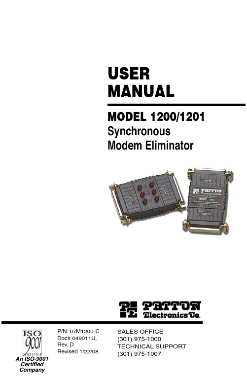
USER MANUALMODEL 1200/1201SynchronousModem EliminatorSALES OFFICE (301) 975-1000TECHNICAL SUPPORT P/N: 07M1200-CDoc# 049011U,Rev. DRevised 1/22/081.0Warranty Information (5)1.1Warranty Statement (5)1.2Radio and TV Interference (5)1.3CE Notice (6)1.4Service (6)2.0General Information (7)2.1Features (7)2.2Description (7)3.0Installation (8)4.0Configuration (9)4.1Data Rate (9)4.2Carrier Detect (9)4.3RTS/CTS Delay (10)4.4Ground (10)5.0Operation (11)5.1LED Status Indicators (Model 1201 only) (11)A Specifications (12)A.1Data Rates (12)A.2Clocking (12)A.3Grounding (12)A.4Range (12)A.5Functional (12)A.6RTS/CTS Delay (12)A.7DCD (12)A.8Ring Indicator (12)A.9Interface (12)A.10Connectors (12)A.11Power Supply (12)A.12Altitude (12)A.13Humidity (12)A.14Dimensions (12)B Block Diagram (13)1.0 WARRANTY INFORMATIONPatton Electronics warrants all Model 1200/1201 components to be free from defects, and will—at our option—repair or replace the product should it fail within one year from the first date of shipment.1.1 WARRANTY STATEMENTPatton Electronics warrants all Model 2701RC Series components to be free from defects, and will—at our option—repair or replace the prod-uct should it fail within one year from the first date of shipment. This war-ranty is limited to defects in workmanship or materials, and does not cover customer damage, abuse, or unauthorized modification. This prod-uct contains no serviceable parts; therefore the user shall not attempt to modify the unit in any way. If this product fails or does not perform as warranted, your sole recourse shall be repair or replacement as described above. Under no condition shall Patton Electronics be liable for any damages incurred by the use of this product. These damages include, but are not limited to, the following: lost profits, lost savings and incidental or consequential damages arising from the use of or inability to use this product. Patton Electronics specifically disclaims all other war-ranties, expressed or implied, and the installation or use of this product shall be deemed an acceptance of these terms by the user. In the event the user detects intermittent or continuous product malfunction due to nearby high power transmitting radio frequency equipment, the user is strongly advised to use only data cables with an external outer shield bonded to a metal or metalized connector.1.2 RADIO AND TV INTERFERENCEThe Model 1200/1201 generates and uses radio frequency energy, and if not installed and used properly-that is, in strict accordance with the man-ufacturer’s instructions-may cause interference to radio and television reception. The Model 1200/1201 has been tested and found to comply with the limits for a Class A computing device in accordance with specifi-cations in Subpart B of Part 15 of FCC rules, which are designed to pro-vide reasonable protection from such interference in a commercial installation. However, there is no guarantee that interference will not occur in a particular installation. If the Model 1200/1201 does cause interference to radio or television reception, which can be determined by disconnecting the unit , the user is encouraged to try to correct the inter-ference by one or more of the following measures: moving the computing equipment away from the receiver, re-orienting the receiving antenna and/or plugging the receiving equipment into a different AC outlet (such that the computing equipment and receiver are on different branches).1.3 CE NOTICEThe CE symbol on your Patton Electronics equipment indicates that it is in compliance with the Electromagnetic Compatibility (EMC) directive and the Low Voltage Directive (LVD) of the European Union (EU). A Cer-tificate of Compliance is available by contacting Technical Support.This device is not intended to be connected to the publictelephone network.Caution1.4 SERVICEAll warranty and nonwarranty repairs must be returned freight prepaid and insured to Patton Electronics. All returns must have a Return Materi-als Authorization number on the outside of the shipping container. This number may be obtained from Patton Electronics T echnical Services at:•Tel: +1(301) 975-1007•Email: ******************•URL: Note Packages received without an RMA number will not beaccepted.2.0 GENERAL INFORMATIONThank you for your purchase of this Patton Electronics product. This product has been thoroughly inspected and tested and is warranted for One Y ear parts and labor. If any questions or problems arise during installation or use of this product, please contact Patton Electronics Customer Service at (301) 975-1007.2.1 FEATURES•Smallest synchronous modem eliminator available•Data rates to 38.4 Kbps•Synchronous cable runs to 300 feet on each side of device •Constant or RTS controlled carrier selections•RTS-CTS delay options of 0mS, 6.6mS or 53mS•DB-25 connector on each end•Half or full duplex•Internal or external clocking•No external power required•LEDs monitor data and control signals (Model 1201 only)2.2 DESCRIPTIONMeasuring only 5.3 x 2 x 1.2 inches, the Patton Model 1200 is the small-est self-powered synchronous modem eliminator on the market. All power is derived from the RS-232 data signals, so no AC power or bat-teries are required. Constructed with a DB-25 connector on each end, the Model 1200 can extend synchronous cable runs to 300 feet on each side of the device. Optimum distance is achieved at 9600 bps, and strap selectable data rates may extend up to 38,400 bps.The Model 1200 provides internal or external clock options and operates half or full duplex. To emulate dial-up or dedicated service, the delay between RTS and CTS can be set to either 0mS, 6.6mS or 53mS. The carrier can be configured either as “constantly on” or “controlled by RTS”. The Model 1201 has all the features of the Model 1200, plus LED indica-tors that monitor receive data, request to send and data carrier detect on each side of the device.Do the following to install the Patton Model 1200:1.Configure according to the instructions listed in section 4.0, “Config-uration” on page 7.2.Turn off the computer or device to which the Model 1200 is to beconnected.3.Plug the DB-25 connectors directly into the serial ports of your RS-232 devices. If you wish to extend the distance, you can add cableson both sides (see Figure 1).Note Cables must not be longer than 300 feet (see Figure 1).Figure 1.ConfigurationThe Model 1200 is equipped with four strapping options that allow config-uration to a wide range of applications. To gain access to the internal straps, loosen the hex nuts on the DB-25 connectors and pry open the case between the plastic shell ears. Figure 2 shows the location of each strapping option.Figure 2. Strap settings for the Model 1200/12014.1 DATA RATEThe data rate strap controls the rate at which data is transmitted. Adjust the strap to select one of the following options: 1.2, 2.4, 4.8, 9.6, 19.2, 38.4 or external clocking. If “external clocking” is selected, the Model 1200 will automatically match the clocking between your two synchro-nous devices. The default setting is 9.6 Kbps.4.2 CARRIER DETECTThe carrier detect straps allow you to determine whether the carrier is “constantly on” or “controlled by RTS”. By adjusting the strap, you may operate in switched carrier, multi-point and/or hardware handshaking applications. Port 1 and port 2 may be configured separately. The defaults setting is “on” for both ports.4.3 RTS/CTS DELAYThe RTS/CTS delay straps determine the amount of delay between the time the Model 1200 “sees” RTS and when it sends CTS. In order to emulate either dial-up or leased line modems, you can set this strap at either no delay, 6.6mS or 53mS. Port 1 and port 2 may be configured separately. The default setting is 6.6mS for both ports.4.4 GROUNDThe ground strap setting connects the protective ground from port 1 or 2 to the Model 1200’s signal ground. The default setting is port 1.5.0 OPERATIONOnce you have configured the Model 1200 properly (see section 4.0, “Configuration” on page 7) and plugged it into your equipment, you are ready to operate the unit. After the Model 1200 is properly installed, it should operate transparently—as if it were a standard cable connection. Operating power is derived from the RS-232 data and control signals; there is no “ON/OFF” switch.5.1 LED STATUS INDICATORS (MODEL 1201 ONLY)The Model 1201 features six front panel status LEDs that indicate the condition of the modem eliminator and the communication link. The dia-gram below shows the location of each of these LEDs. Following the dia-gram is a description of each LED’s function.•“TD” and “RTS” indicators blink with data activity.•“CD” lights for an incoming signal on the line side and the resulting out-put signal on the RS-232.APPENDIX ASPECIFICATIONSA.1 DATA RATESSelectable: 1200, 2400, 4800, 9600, 19200, 38400A.2 CLOCKINGInternal or externalA.3 GROUNDINGProtective ground (pin 1) may be strapped to signal ground (pin 7)A.4 RANGE300 feet on either side (for a total of 600 feet) at 9600 bps, range extends linearly for lower bit rates and decreases for higher bit ratesA.5 FUNCTIONALEmulates half or full duplex, dial-up or dedicated lineA.6 RTS/CTS DELAYSelectable per port: 0mS, 6.6mS, 53mSA.7 DCDSelectable per port: continuous or RTS controlledA.8 RING INDICATORConstantly onA.9 INTERFACEEIA RS-232C/CCITT V.24A.10 CONNECTORSChoice of two male or two female DB-25 RS-232 connectorsA.11 POWER SUPPLYNone requiredA.12 ALTITUDE0 to 10,000 feetA.13 HUMIDITYUp to 95% non-condensingA.14 DIMENSIONSApproximately 5.3 x 2 x 1.2 in.APPENDIX BBLOCK DIAGRAMCopyright © 2001 Patton Electronics Company All Rights Reserved.Dear Valued Customer,Thank you for purchasing Patton Electronics products! We do appreci-ate your business. I trust that you find this user manual helpful.We manufacture one of the widest selections of data communications products in the world including CSU/DSU's, network termination units, powered and self-powered short range modems, fiber optic modems, interface converters, baluns, electronic data switches, data-line surge protectors, multiplexers, transceivers, hubs, print servers and much more. We produce these products at our Gaithersburg, MD, USA, facility, and can custom manufacture products for your unique needs.We would like to hear from you. Please contact us in any of the following ways to tell us how you like this product and how we can meet your prod-uct needs today and in the future.Web: Sales E-mail: ****************SupportE-mail:******************Phone - Sales (301) 975-1000Phone - Support (301) 975-1007Fax: (301) 869-9293Mail: Patton Electronics Company7622 Rickenbacker DriveGaithersburg, MD 20879 USAWe are committed to a quality product at a quality price. Patton Electron-ics is ISO 9001 certified. We meet and exceed the highest standards in the industry (CE, UL, etc.).It is our business to serve you. If you are not satisfied with any aspect of this product or service provided by Patton Electronics or its distributors, please let us know.Thank you.Burton A.PattonVice PresidentP.S. Please tell us where you purchased this product.________________________________________________________ ________________________________________________________ ________________________________________________________。
- 1、下载文档前请自行甄别文档内容的完整性,平台不提供额外的编辑、内容补充、找答案等附加服务。
- 2、"仅部分预览"的文档,不可在线预览部分如存在完整性等问题,可反馈申请退款(可完整预览的文档不适用该条件!)。
- 3、如文档侵犯您的权益,请联系客服反馈,我们会尽快为您处理(人工客服工作时间:9:00-18:30)。
功能描述
BT1200C 是一个高集成度、低成本、低功耗的蓝牙立体声音频模块。
符合Bluetooth 2.0规范。
支持A2DP V1.2,AVRCP V1.4,HSP1.2,HFP1.5 profiles 。
集成EEPROM ,可配置工作模式及参数 内部MIC 偏压供给 内部MIC 放大器
UART 支持来电号码指示(要求手机端对此功能的支持)
立体声音频输出可直接驱动40mW@32Ω speeker 而不需要隔直电容 集成上电复位及可编程的低电压监测功能
六个按键输入,包括开关机键、配对键、音量加、音量减、上一曲、下一曲 两个指示灯用于指示不同的工作状
来电时具有提示音,如手机端支持则可播放来电铃声
短按ONKEY 开关机键可接听或挂断电话,长按可拒接来电,超长按可踢出手机连接,短按2次可重拨最后一次去电.
播放/暂停时单独IO 口输出H 或L 电平来控制PA ,使得在LAYOUT 没有处理好的情况下
也不会有噪声。
技术参数
CATEGORIES FEATURE IMPLEMENTATION Bluetooth Version 2.0 Frequency 2.402‐2.480GHz Class2
Max Transmit Power 4dBm (at antenna pad ) Receive Sensitivity
Better than ‐82dBm Range 10meters
Wireless Specification
Data Rates
Up to 3Mbps (over the air )
UART DATA Transfer Rate
115200bps Host Interface UART No flow control support
Audio Interfaces Microphone
Mono microphone input with bias A2DP V1.2–Sink Only AVRCP V1.4 –Controller Only HSP V1.2 Profiles
HFP V1.5
Supply Voltage Supply 3.6V – 4.2V DC
Operational ‐ Less than 55 mA (active) Power
Consumption Current
Consumption Idle (sleep) < 10mA Connections External Antenna Connection via SMT pad Physical
Dimensions
15.7mm x 23.3mm x 1.85mm
PIN 脚定义
序号 名称 类型 描述
1 XO OSC 振荡器测试信号
2 AOM Audio 音频输出公共端0.9V 不能为地
3 AOL Audio 左声道音频输出
4 AOR Audio 右声道音频输出
5 MIC+ Audio MIC 输入端
6 MICBIAS Power MIC 偏压输出
7 LED1 Sink 指示灯1控制端
8 LED2 Sink 指示灯2控制端
9 VCC NC 空脚 10 VBUCK Digital 外部复位 11 GND Power 地
12 VBAT Power 电池供电端3.6V ‐4.2V 13 1V8 Power LDO 输出 1.8V
14 ONKEY Digital 开关机按键/播放/暂停按键信号 15 VOL+ Digital 音量加按键信号/复用下一曲 16
VOL ‐
Digital
音量减按键信号/复用上一曲
17 RESET Digital 兼容I2C数据信号
18 NC Digital 兼容I2C时钟信号
19 MFB1 Digital 配对按键信号/开机自动配对
20 UART_TX Digital UART发送信号
21 UART_RX Digital UART接收信号
22 Next Digital 下一曲
23 Prev Digital 上一曲
24 MUTE Digital 播放/暂停输出高或低
25 VPP Power 编程电压
26 GND1 Power 地
27 ANT RF 天线端
28 GND2 Power 地
尺寸图
应用参考电路
模块应用(BT1200C):
单功放应用(LM4871 SOP8):
单功放应用:
双功放应用(BT8063 SOP16):
运放应用(LM358 SOP8):
已知问题列表
1、 部分手机的播放器由于不具备渐入渐出功能,在歌曲播放暂停间有POP 音.
2、 由于蓝牙的断线检测为非实时操作,关闭音箱手机端断开有延迟.
3、 自动回联功能与自动关机功能互斥,打开自动回联功能后不能实现自动关机.
4、 当机内配对列表中存在已配对设备并打开自动回联功能时,自动回联动作可能与手机端
配对动作发生碰撞导致偶尔出现配对失败的现象.
5、 上电瞬间音频输出端有短暂的悬空状态,音箱会发出一声电流声.
6、 由于没有硬件的回音消除电路,做免提应用时主要依赖结构设计来避免回音.
7、 部分国产手机,在连接过程中只能配对但不能连接,是因为手机端软件需检测到免提装
置才可连接,需将蓝牙免提功能打开.。
