76015-1603;76015-3603;中文规格书,Datasheet资料
LX750_LX760说明书
II.2.A.C LCD 亮度 ......................................................................................................... 16 II.2.A.D II.2.A.E II.2.A.F II.2.A.G LCD 反显 ...................................................................................................... 16 电源频率 ...................................................................................................... 16 开机自我测试................................................................................................ 17 系统语言 ...................................................................................................... 17
CHAPTER
II.1
II
功能设定与分析模式 ......................................................................... 11
系统主功能 (FUNCTION) ...................................................................................... 11
BD1603NUV资料

Please contact our sales offices for details ;
U.S.A / San Diego Atlanta Dallas Germany / Dusseldorf TEL : +1(858)625-3630 TEL : +1(770)754-5972 TEL : +1(972)312-8818 TEL : +49(2154)9210 FAX : +1(858)625-3670 FAX : +1(770)754-0691 FAX : +1(972)312-0330 FAX : +49(2154)921400 FAX : +44(1)908-282-528
Japan / (Internal Sales)
Tokyo Yokohama Nagoya Kyoto 2-1-1, Yaesu, Chuo-ku, Tokyo 104-0082 TEL : +81(3)5203-0321 FAX : +81(3)5203-0300 2-4-8, Shin Yokohama, Kohoku-ku, Yokohama, Kanagawa 222-8575 TEL : +81(45)476-2131 FAX : +81(45)476-2128 Dainagayo Building 9F 3-28-12, Meieki, Nakamura-ku, Nagoya,Aichi 450-0002 TEL : +81(52)581-8521 FAX : +81(52)561-2173 579-32 Higashi Shiokouji-cho, Karasuma Nishi-iru, Shiokoujidori, Shimogyo-ku, Kyoto 600-8216 TEL : +81(75)311-2121 FAX : +81(75)314-6559 TEL : +81(45)476-9270 FAX : +81(045)476-9271
1150 型号说明书

Thermo Fisher Scientific Air Quality Instruments 27 Forge Parkway Franklin, MA 02038 1-508-520-0430 /aqi
WEEE iance
This product is required to comply with the European Union’s Waste Electrical & Electronic Equipment (WEEE) Directive 2002/96/EC. It is marked with the following symbol:
Z515中文资料(Intel)中文数据手册「EasyDatasheet - 矽搜」
3.3 去耦指南................................................ ............................ 28
3.3.1 3.3.2
V CC 去耦................................................. ........................ 28 FSB AGTL +解耦............................................... ............... 28
Contact your local Intel sales office or your distributor to obtain the latest specifications and before placing your product order. Copie s of docum ents which have an orde r num be r and are re fere nce d in this docum ent, or othe r Inte l lite rature , m ay be obtaine d
Hyper-Threading Technology requires a com puter system with a processor supporting Hyper-Threading Technology and HT Technology enabled chipset, BIO S and operating system . Perform ance will vary depending on the specific hardware and software
PIC16LF1508-ISS;PIC16F1508-ISS;PIC16LF1509-ISS;PIC16F1509-ISS;中文规格书,Datasheet资料
Trademarks The Microchip name and logo, the Microchip logo, dsPIC, KEELOQ, KEELOQ logo, MPLAB, PIC, PICmicro, PICSTART, PIC32 logo, rfPIC and UNI/O are registered trademarks of Microchip Technology Incorporated in the U.S.A. and other countries. FilterLab, Hampshire, HI-TECH C, Linear Active Thermistor, MXDEV, MXLAB, SEEVAL and The Embedded Control Solutions Company are registered trademarks of Microchip Technology Incorporated in the U.S.A. Analog-for-the-Digital Age, Application Maestro, chipKIT, chipKIT logo, CodeGuard, dsPICDEM, , dsPICworks, dsSPEAK, ECAN, ECONOMONITOR, FanSense, HI-TIDE, In-Circuit Serial Programming, ICSP, Mindi, MiWi, MPASM, MPLAB Certified logo, MPLIB, MPLINK, mTouch, Omniscient Code Generation, PICC, PICC-18, PICDEM, , PICkit, PICtail, REAL ICE, rfLAB, Select Mode, Total Endurance, TSHARC, UniWinDriver, WiperLock and ZENA are trademarks of Microchip Technology Incorporated in the U.S.A. and other countries. SQTP is a service mark of Microchip Technology Incorporated in the U.S.A. All other trademarks mentioned herein are property of their respective companies. © 2011, Microchip Technology Incorporated, Printed in the U.S.A., All Rights Reserved. Printed on recycled paper. ISBN: 978-1-61341-726-3
PC123X1YSZ0F, 规格书,Datasheet 资料

PC123XNNSZ0F Series DIP 4pin Reinforced Insulation Type Photocoupler■DescriptionPC123XNNSZ0F Series contains an IRED optically coupled to a phototransistor.It is packaged in a 4-pin DIP, available in wide-lead spacing option and SMT gullwing lead-form option. Input-output isolation voltage(rms) is 5kV.CTR is 50% to 400% at input current of 5mA■Features1. 4-pin DIP package2. Double transfer mold package (Ideal for Flow Solder-ing)3. Current transfer ratio (CTR : MIN. 50% at I F=5 mA, V CE=5V)4. Several CTR ranks available5. Reinforced insulation type (Isolation distance : MIN.0.4mm)6. Long creepage distance type (wide lead-form type only : MIN. 8mm)7. High isolation voltage between input and output (V iso(rms) : 5kV)8. Lead-free and RoHS directive compliant ■Agency approvals/Compliance1. Recognized by UL1577 (Double protection isolation), fi le No. E64380 (as model No. PC123)2. Approved by BSI, BS-EN60065, file No. 7087, BS-EN60950 fi le No. 7409, (as model No. PC123)3. Approved by SEMKO, EN60065, EN60950, (as mod-el No. PC123)4. Approved by DEMKO, EN60065, EN60950, (as mod-el No. PC123)5. Approved by NEMKO, EN60065, EN60950, (as mod-el No. PC123)6. Approved by FIMKO, EN60065, EN60950, (as model No. PC123)7. Recognized by CSA fi le No. CA95323, (as model No. PC123)8. Approved by VDE, DIN EN60747-5-2(∗) (as an op-tion), fi le No. 40008087 (as model No. PC123)9. Package resin : UL fl ammability grade (94V - 0)(∗) DIN EN60747-5-2 : successor standard of DIN VDE0884.■Applications1. I/O isolation for MCUs (Micro Controller Units)2. Noise suppression in switching circuits3. Signal transmission between circuits of different po-tentials and impedances4. Over voltage detectionNotice The content of data sheet is subject to change without prior notice.In the absence of confi rmation by device specifi cation sheets, SHARP takes no responsibility for any defects that may occur in equipment using any SHARP■Internal Connection Diagram■Outline Dimensions(Unit : mm)Anode Cathode Emitter Collector(Unit : mm)Date code (2 digit)1st digit2nd digitYear of production Month of productionA.D.Mark A.D.Mark Month Mark1990A2002P January1 1991B2003R February2 1992C2004S March3 1993D2005T April4 1994E2006U May5 1995F2007V June6 1996H2008W July7 1997J2009X August8 1998K2010A September9 1999L2011B October O 2000M2012C November N 2001N::December Drepeats in a 20 year cycleFactory identifi cation mark and Plating material* Up to Date code "T4" (April 2005), SnBi (Bi : TYP. 2%).** This factory marking is for identifi cation purpose only.Please contact the local SHARP sales representative to see the actural status of the production.Rank markRefer to the Model Line-up table.(T a=25̊C) Parameter Symbol Rating UnitInputForward current I F50mA *1Peak forward current I FM1A Reverse voltage V R6V Power dissipation P70mWOutput Collector-emitter voltage V CEO70V Emitter-collector voltage V ECO6V Collector current I C50mA Collector power dissipation P C150mWTotal power dissipation P tot200mW*2Isolation voltage V iso(rms)5 kVOperating temperature T opr−30 to +100̊CStorage temperature T stg−55 to +125̊C*2Soldering temperature T sol 260̊C*1 Pulse width≤100ms, Duty ratio : 0.001*2 40 to 60%RH, AC for 1 minute, f = 60Hz*3 For 10s■Absolute Maximum Ratings■Electro-optical Characteristics(Ta=25̊C) Parameter Symbol Condition MIN.TYP.MAX.UnitInput Forward voltage V F I F=20mA − 1.2 1.4V Reverse current I R V R=4V−−10μA Terminal capacitance C t V=0, f=1kHz−30250pFOutput Collector dark current I CEO V CE=50V, I F=0 −−100nA Collector-emitter breakdown voltage BV CEO I C=0.1mA, I F=0 70−−V Emitter-collector breakdown voltage BV ECO I E=10μA, I F=0 6−−nATransfer charac−teristics Collector current I C I F=5mA, V CE=5V 2.5−20mA Collector-emitter saturation voltage V CE(sat)I F=20mA, I C=1mA−0.10.2V Isolation resistance R ISO DC500V, 40 to 60%RH5×10101×1011−ΩFloating capacitance C f V=0, f=1MHz−0.61pF Cut-off frequency f C V CE=5V, I C=2mA, R L=100Ω, −3dB−80−kHzResponse timeRise time t rV CE=2V, I C=2mA, R L=100Ω−418μs Fall time t f−318μs■Model Line-upLead Form Through-Hole Wide Through-HoleRank markI C[mA] (I F=5mA, V CE=5V, T a=25˚C)PackageSleeve 100pcs/sleeveDINEN60747-5-2−Approved−ApprovedModel No.PC123XNNSZ0F PC123XNYSZ0F PC123XNNFZ0F PC123XNYFZ0F With or without 2.5 to 20 PC123X1NSZ0F PC123X1YSZ0F PC123X1NFZ0F PC123X1YFZ0F L 2.5 to 7.5 PC123X2NSZ0F PC123X2YSZ0F PC123X2NFZ0F PC123X2YFZ0F M 5 to 12.5 PC123X5NSZ0F PC123X5YSZ0F PC123X5NFZ0F PC123X5YFZ0F N10 to 20 PC123X8NSZ0F PC123X8YSZ0F PC123X8NFZ0F PC123X8YFZ0F E 5 to 10Lead Form SMT Gullwing Wide SMT GullwingRank markI C[mA] (I F=5mA, V CE=5V, T a=25˚C)PackageTaping2 000pcs/reelDINEN60747-5-2−Approved−ApprovedModel No.−PC123XNYIP0F PC123XNNUP0F PC123XNYUP0F With or without 2.5 to 20 PC123X1YIP0F PC123X1NUP0F PC123X1YUP0F L 2.5 to 7.5 PC123X2YIP0F PC123X2NUP0F PC123X2YUP0F M 5 to 12.5 PC123X5YIP0F PC123X5NUP0F PC123X5YUP0F N10 to 20 PC123X8YIP0F PC123X8NUP0F PC123X8YUP0F E 5 to 10Please contact a local SHARP sales representative to inquire about production status.Fig.1 Forward Current vs. Ambient TemperatureFig.2 Diode Power Dissipation vs. Ambient TemperatureFig.3 Collector Power Dissipation vs. Ambient TemperatureFig.4 Total Power Dissipation vs. AmbientTemperatureFig.5 Peak Forward Current vs. Duty RatioFig.6 Forward Current vs. Forward Voltage101001F o r w a r d c u r r e n t I F (m A )Forward voltage V F (V)Duty ratioPulse width ≤100μs T a =25˚C10100101010P e a k f o r w a r d c u r r e n t I F M (m A )10 0001 0001F o r w a r d c u r r e n t I F (m A )Ambient temperature T a (˚C)05040302010−30025505575100125D i o d e p o w e r d i s s i p a t i o n P (m W )Ambient temperature T a (˚C)010*******4020−30025505575100125C o l l e c t o r p o w e r d i s s i p a t i o n P C (m W )Ambient temperature T a (˚C)025020015010050−30255075100125T o t a l P o w e r d i s s i p a t i o n P t o t (m W )Ambient temperature T a (˚C)025020015010050−300255075100125Fig.7 Current Transfer Ratio vs. Forward CurrentFig.8 Collector Current vs. Collector-emitter VoltageFig.9 Relative Current Transfer Ratio vs. Ambient TemperatureFig.10 Collector - emitter Saturation Voltage vs. Ambient TemperatureFig.11 Collector Dark Current vs. Ambient TemperatureFig.12 Response Time vs.Load ResistanceR e s p o n s e t i m e (μs )0.010.11101000.1110100V CE =2VI C =2mA T a =25˚Ct rt ft dt s1 000Load resistance (k Ω)Ambient temperature T a (˚C)C o l l e c t o r d a r k c u r r e n t I C E O (A )−30020*********10−1110−1010−910−810−710−610−5V CE =50VForward current I F (mA)C u r r e n t t r a n s f e r r a t i o C T R (%)0.111010050100150200250300V CE =5V T a =25˚CCollector-emitter voltage V CE (V)0123456789106121824303642485460T a =25˚CI F =30m A I F =20m AI F =10m AI F =5mAC o l l e c t o r c u r r e n t I C (m A )P C (MAX.)500100150025*******R e l a t i v e c u r r e n t t r a n s f e r r a t i o (%)−30I F =5mAV CE =5VAmbient temperature T a (˚C)Ambient temperature T a (˚C)C o l l e c t o r -e m i t t e r s a t u r a t i o n v o l t a g e V C E (s a t ) (V )−30204060801000.020.040.060.080.10.120.140.16I F =20mA I C =1mAFig.13 Test Circuit for Response Time Fig.14 Frequency ResponseFig.15 Collector-emitter Saturation Voltage vs. Forward CurrentRemarks : Please be aware that all data in the graph are just for reference and not for guarantee.CEPlease refer to the conditions in Fig.12.Frequency (kHz)V o l t a g e g a i n A v (d B )0.110100−201−15−10−55V CE =5V I C =2mA T a =25˚CR L =10k Ω1k Ω100Ω1 000Forward current I F (mA)C o l l e c t o r -e m i t t e r s a t u r a t i o n v o l t a g e V C E (s a t ) (V )00.511.522.533.544.55■Design Considerations●Design guideWhile operating at I F<1mA, CTR variation may increase.Please make design considering this fact.This product is not designed against irradiation and incorporates non-coherent IRED.●DegradationIn general, the emission of the IRED used in photocouplers will degrade over time.In the case of long term operation, please take the general IRED degradation (50% degradation over 5 years) into the design consideration.●Recommended foot print (reference)SMT Gullwing lead-form Wide SMT Gullwing lead-form(Unit : mm)✩ For additional design assistance, please review our corresponding Optoelectronic Application Notes.■Manufacturing Guidelines ●Soldering Method Re fl ow Soldering :Re fl ow soldering should follow the temperature pro fi le shown below.Soldering should not exceed the curve of temperature pro fi le and time.Please don't solder more than twice.Flow Soldering :Due to SHARP's double transfer mold construction submersion in fl ow solder bath is allowed under the be-low listed guidelines.Flow soldering should be completed below 270̊C and within 10s.Preheating is within the bounds of 100 to 150̊C and 30 to 80s.Please don't solder more than twice.Hand solderingHand soldering should be completed within 3s when the point of solder iron is below 400̊C.Please don't solder more than twiceOther noticePlease test the soldering method in actual condition and make sure the soldering works fi ne, since the im-pact on the junction between the device and PCB varies depending on the tooling and soldering conditions.12343002001000(˚C)(min)●Cleaning instructionsSolvent cleaning :Solvent temperature should be 45˚C or below. Immersion time should be 3 minutes or less.Ultrasonic cleaning :The impact on the device varies depending on the size of the cleaning bath, ultrasonic output, cleaning time, size of PCB and mounting method of the device.Therefore, please make sure the device withstands the ultrasonic cleaning in actual conditions in advance of mass production.Recommended solvent materials :Ethyl alcohol, Methyl alcohol and Isopropyl alcohol.In case the other type of solvent materials are intended to be used, please make sure they work fi ne in ac-tual using conditions since some materials may erode the packaging resin.●Presence of ODCThis product shall not contain the following materials.And they are not used in the production process for this product.Regulation substances : CFCs, Halon, Carbon tetrachloride, 1.1.1-Trichloroethane (Methylchloroform)Specifi c brominated fl ame retardants such as the PBB and PBDE are not used in this product at all.This product shall not contain the following materials banned in the RoHS Directive (2002/95/EC).•Lead, Mercury, Cadmium, Hexavalent chromium, Polybrominated biphenyls (PBB), Polybrominateddiphenyl ethers (PBDE).■Package specifi cation●Sleeve package1. Through-HolePackage materialsSleeve : HIPS (with anti-static material)Stopper : Styrene-ElastomerPackage methodMAX. 100pcs of products shall be packaged in a sleeve. Both ends shall be closed by tabbed and tabless stoppers.The product shall be arranged in the sleeve with its anode mark on the tabless stopper side.MAX. 20 sleeves in one case.Sleeve outline dimensions2. Wide Through-HolePackage materialsSleeve : HIPS (with anti-static material)Stopper : Styrene-ElastomerPackage methodMAX. 100pcs of products shall be packaged in a sleeve. Both ends shall be closed by tabbed and tabless stoppers.The product shall be arranged in the sleeve with its anode mark on the tabless stopper side.MAX. 20 sleeves in one case.Sleeve outline dimensions●Tape and Reel package1. SMT GullwingPackage materialsCarrier tape : PSCover tape : PET (three layer system)Reel : PSCarrier tape structure and DimensionsDimensions List(Unit : mm)A 16.0±0.3B7.5±0.1C1.75±0.10D8.0±0.1E2.0±0.1H 10.4±0.1I0.40±0.05J4.2±0.1K5.1±0.1F4.0±0.1Gφ1.5+0.1−0.0Reel structure and DimensionsDimensions List(Unit : mm)aφ330b17.5±1.5cφ100±1dφ13.0±0.5eφ23±1f2.0±0.5g2.0±0.5 Direction of product insertionPull-out direction2. Wide SMT GullwingPackage materialsCarrier tape : PSCover tape : PET (three layer system)Reel : PSCarrier tape structure and DimensionsDimensions ListA 24.0±0.3B11.5±0.1C1.75±0.10D8.0±0.1E2.0±0.1H 12.4±0.1I0.40±0.05J4.1±0.1K5.1±0.1F4.0±0.1Gφ1.5+0.1−0.0(Unit : mm)Reel structure and DimensionsDimensions List(Unit : mm) aφ330b25.5±1.5cφ100±1dφ13.0±0.5 eφ23±1f2.0±0.5g2.0±0.5Direction of product insertionPull-out direction■Important Notices· The circuit application examples in this publication are provided to explain representative applications of SHARP devices and are not intended to guarantee any circuit design or license any intellectual property rights. SHARP takes no responsibility for any problems related to any intellectual property right of a third party resulting from the use of SHARP's devices.· Contact SHARP in order to obtain the latest device specification sheets before using any SHARP device. SHARP reserves the right to make changes in the specifi cations, characteristics, data, materials, structure, and other contents described herein at any time without notice in order to improve design or reliability. Manufacturing locations are also subject to change without notice.· Observe the following points when using any devices in this publication. SHARP takes no responsibility for damage caused by improper use of the devices which does not meet the conditions and absolute maximum ratings to be used specifi ed in the relevant specifi cation sheet nor meet the following conditions:(i) The devices in this publication are designed for use in general electronic equipment designs such as:--- Personal computers--- Offi ce automation equipment--- Telecommunication equipment [terminal]--- Test and measurement equipment--- Industrial control--- Audio visual equipment--- Consumer electronics(ii) Measures such as fail-safe function and redundant design should be taken to ensure reliability and safety when SHARP devices are used for or in connection with equipment that requires higher reliability such as:--- Transportation control and safety equipment (i.e., aircraft, trains, automobiles, etc.)--- Traffi c signals--- Gas leakage sensor breakers--- Alarm equipment--- Various safety devices, etc.(iii) SHARP devices shall not be used for or in connection with equipment that requires an extremely high level of reliability and safety such as:--- Space applications--- Telecommunication equipment [trunk lines]--- Nuclear power control equipment--- Medical and other life support equipment (e.g., scuba).· If the SHARP devices listed in this publication fall within the scope of strategic products described in the Foreign Exchange and Foreign Trade Law of Japan, it is necessary to obtain approval to export such SHARP devices.· This publication is the proprietary product of SHARP and is copyrighted, with all rights reserved. Under the copyright laws, no part of this publication may be reproduced or transmitted in any form or by any means, electronic or mechanical, for any purpose, in whole or in part, without the express written permission of SHARP. Express written permission is also required before any use of this publication may be made by a third party.· Contact and consult with a SHARP representative if there are any questions about the contents of this publication.。
9070T150D1产品数据表说明书

9070T150D1Industrial Control TransformersProduct Description PRODUCT DESCRIPTIONControl power transformers from Schneider Electric set the industry standard for design innovation and performance. They are designed with low impedance windings for excellent voltage regulation, and can accomodate the high inrush current associated with contactors, starters, solenoids, and relays.A variety of designs are available to meet the diverse needs of panel builders and machinery OEMs. The versatility of our control transformer line offers unparalleled options for design engineers. We also have one of the most extensive offering of custom products with no minimum order requirements.We have a national network of distributors to ensure prompt delivery, including industry leading delivery on custom products. In most cases, we can design, manufacture, and ship a custom unit in two weeks or less.The Global Product Offering—Type TType T is our most popular and complete line of control transformers. It comes with unmatched design innovations for top performance and is manufactured using the most advanced insulating materials. The Type T control transformer is the best choice if size and cost are of concern.The Exceptional Regulation Offering —Type EOConstructed with traditional materials and manufacturing processes, Type EO transformers are UL and CSA Component Recognized. Units are designed for 55°C rise. All units are 60HZ rated, withde-rated VA levels for 50HZ.Transformers with Fuse Block Protection—Types TF and EOFWe offer both product lines with factory installed overcurrent protection fuse blocks.Type TF and EOF transformers consist of two primary fuse blocks and one secondary fuse block, a configuration that meets the majority of overcurrent needs by panel builders and machinery OEMs. Since the fuse blocks are pre-wired and mounted on top of the transformer, the Type TF and EOF transformers have the same footprint as the Type T and Type EO units, respectively. This design frees up space normally used for separate fuse blocksWe also have an extensive fuse block offering for custom applications. See the overcurrent section of this catalog for full details.Leaded Control Transformer LineSchneider Electric offers transformers with internally pre-wired 24-inch primary and secondary leads, instead of terminal boards, to make installation easier and faster for many applications. These are only available for single voltage primary and single voltage secondary applications.MultiTapSchneider Electric offers Type T and Type EO transformers in the MultiTap version. The MultiTap control transformer was designed to respond to the increased need for voltage and stock flexibility. It combines multiple primary voltages with one or more secondary voltages, all in a single transfomer. The most flexible MultiTap voltage is the Universal, available on the Type T product line only. It allows for standard primary voltages of 208 to 600V and 110, 115, or 120V secondary voltages.Industrial Control TransformersType T TransformersTYPE T TRANSFORMERSThe Type T units are designed for the global market and are the best choice when size and cost are of concern. This is our most popular and complete offering of industrial control transformers. The following features are included:•50/60 Hz rated•Customer installed accessories (Finger-Safe covers, fuse blocks, fuse clips)•Type T transformers are designed with various temperature classes:—25–150 VA with a 55° C temperature rise, 105° C insulation —200–350 VA with a 80° C temperature rise, 130° C insulation —500–5000 VA with a 115° C temperature rise, 180° C insulationSchneider Electric manufactures a wide variety of voltage combinations for control transformers. The voltage combinations are expressed as “Voltage Codes”, and are embedded within the catalog number of the transformer. Standard codes are listed. If the voltage combination you need is not listed, please call your Schneider Electric distributor for assistance.CE MarkingIndustrial control transformers (ICTs) entering the European Union (EU) after January 1, 1997 are required by EU standards to have CE marking or Declaration of Conformity to CE. EU documentation requires compliance with specification EN 61 558 of the Low Voltage Directive. Type T ICTs from Schneider Electric comply with this specification and are third party tested to T ÜV standards, which adhere to, and are accepted by, EU standards. A Declaration of Conformity for all Type T units is available upon request.Because of different overload criteria in the CE specification,Schneider Elecric dual rates these transformers for UL VA, cUL VA, CSA VA, NOM VA and CE VA ratings (see “Type T VA Ratings” table). Because they are widely used with control circuit panels, ICTs are also required to comply with EN 60 204 and EN 61 558 in these applications. The Type T transformer line complies with EN 60 204 when Fingersafe ® covers are installed.For more information regarding CE marking, please contact your local Schneider Electric field sales office.Type T VA RatingsUL, cUL, CSA and NOM VA RatingCEVA Rating252550507575100100150150200200250160300200350250500300750500100063015001000200015003000200050003000Type T ListingsListingFileVA RangeUL E61239, Guide XPTQ225–5000cUL E612391500–5000CSALR37055, Guide 184-N-9025–1000EN947923, EN 61 558/01.89 (TUV ref: 00941-RAG/sg E9371495E01)25–2009579078, EN 61 558/01.89 (TUV ref: 00941-RAG/sg E9471921E01)250–10009579078, EN 61 558/01.89 (TUV ref: 00941-RAG/sg E9471921.02E01)1500–3000Industrial Control TransformersType T Transformers120 Volt Control SecondaryVoltage and Connection OptionsVoltage CodeVoltagesConnectionsPrimary SecondaryPrimarySecondaryD1220 x 440230 x 460240 x 480110115120220/230/240 V:Connect to H1 and H4Jumper H1 with H3Jumper H2 with H4440/460/480 V:Connect to H1 and H4Jumper H2 with H3Connect to X1 and X2DimensionsVA CatalogNumberFigureAcc. KeyA BCEFSlotsULCEINmmINmmINmmINmmINmmINmm25259070T25D11I 3.0979 3.0076 2.5866 2.0051 2.50640.20 x 0.38 5 x 1050509070T50D11I 3.0979 3.0076 2.5866 2.0051 2.50640.20 x 0.38 5 x 1075759070T75D11I 3.3485 3.3886 2.8973 2.3861 2.81710.20 x 0.48 5 x 121001009070T100D11I 3.3485 3.3886 2.8973 2.3861 2.81710.20 x 0.48 5 x 121501509070T150D11I 3.5991 3.7595 3.2081 2.8873 3.13800.20 x 0.38 5 x 102002009070T200D11I 3.5991 3.7595 3.2081 2.8873 3.13800.20 x 0.38 5 x 102501609070T250D12I 5.30135 3.7595 3.2182 2.8873 3.13800.20 x 0.38 5 x 103002009070T300D12I 4.74120 4.50114 3.8498 2.5665 3.75950.20 x 0.38 5 x 103502509070T350D12I 5.11130 4.50114 3.8498 3.0076 3.75950.20 x 0.38 5 x 105003009070T500D12I 5.49139 4.50114 3.8498 3.5690 3.75950.20 x 0.38 5 x 107505009070T750D12I 5.61143 5.25133 4.51115 3.4387 4.381110.28 x 0.567 x 1410006309070T1000D12I 6.30160 5.25133 4.51115 4.31109 4.381110.28 x 0.567 x 14150010009070T1500D12I 5.921507.06179 6.17157 4.13105 5.811480.28 x 0.567 x 14200015009070T2000D12I 7.171827.06179 6.17157 4.56116 5.811480.28 x 0.567 x 14300020009070T3000D13I 7.241849.002298.75222 4.631187.631940.44 x 1.1311 x 29500030009070T5000D13I9.152329.002298.752226.561677.631940.44 x 1.1311 x 2914T R A N S F O R M E R SIndustrial ControlClass 9070 / Refer to Catalogs 9070CT9901, 7400CT9601Square D ® Type T and MultiTap™ TransformersType T transformers are designed with low impedance windings forexcellent voltage regulation and can accommodate the high inrush current associated with contactors, starters, solenoids, and relays. As the most popular and complete line of control transformers with unmatched design innovations for top performance, Type Ts are manufactured using the most advanced insulating materials and are the best choice if size and cost are of concern. It is available in the MultiTap version, designed to respond to the increased need for voltage and stock flexibility. It combines multiple primary voltages with one or more secondary voltages, all in a single transformer.VAVA Catalog No.$ PriceH W D W e i g h t (l b s )U L /C S A /N O MCEin (mm)in (mm)in (mm)Primary 240 x 480 Secondary 120; Primary 230 x 460 Secondary 115; or Primary 220 x 440Secondary 11025259070T25D174.00 2.58 (65.5) 3.00 (76.2) 3.09 (78.5) 2.550509070T50D177.00 2.58 (65.5) 3.00 (76.2) 3.09 (78.5) 2.575759070T75D192.00 2.89 (73.4) 3.38 (85.8) 3.34 (84.8) 3.81001009070T100D1103.00 2.89 (73.4) 3.38 (85.8) 3.34 (84.8) 3.81501509070T150D1110.00 3.20 (81.3) 3.75 (95.3) 3.59 (91.2) 5.52002009070T200D1136.00 3.20 (81.3) 3.75 (95.3) 3.59 (91.2) 5.52501609070T250D1159.00 3.25 (82.6) 3.75 (95.3) 5.25 (133.4)7.130********T300D1176.00 3.80 (96.5) 4.50 (114.3) 4.70 (119.4)8.53502509070T350D1187.00 3.80 (96.5) 4.50 (114.3) 5.09 (129.3)10.55003009070T500D1233.00 3.80 (96.5) 4.50 (114.3) 5.46 (138.7)11.97505009070T750D1322.00 4.43 (112.5) 5.25 (133.4) 5.66 (143.8)11.010*********T1000D1390.00 4.43 (112.5) 5.25 (133.4) 6.04 (153.4)20.6150010009070T1500D1558.00 6.16 (156.5)7.06 (179.3) 5.81 (147.6)34.0200015009070T2000D1678.00 6.16 (156.5)7.06 (179.3)7.04 (178.8)47.0300020009070T3000D1941.008.46 (214.9)9.00 (228.6) 6.86 (174.2)60.0500030009070T5000D11582.008.46 (214.9)9.00 (228.6)8.73 (221.7)89.0Primary 208 Secondary 12050509070T50D390.00 2.58 (65.5) 3.00 (76.2) 3.09 (78.5) 2.575759070T75D3108.00 2.89 (73.4) 3.38 (85.8) 3.34 (84.8) 3.81001009070T100D3121.00 2.89 (73.4) 3.38 (85.8) 3.34 (84.8) 3.81501509070T150D3153.00 3.20 (81.3) 3.75 (95.3) 3.59 (91.2) 5.52002009070T200D3195.00 3.20 (81.3) 3.75 (95.3) 3.59 (91.2) 5.52501609070T250D3242.00 3.25 (82.6) 3.75 (95.3) 5.25 (133.4)7.130********T300D3248.00 3.80 (96.5) 4.50 (114.3) 4.70 (119.4)8.53502509070T350D3288.00 3.80 (96.5) 4.50 (114.3) 5.09 (129.3)10.55003009070T500D3314.00 3.80 (96.5) 4.50 (114.3) 5.46 (138.7)11.97505009070T750D3443.00 4.43 (112.5) 5.25 (133.4) 5.66 (143.8)11.010*********T1000D3558.00 4.43 (112.5) 5.25 (133.4) 6.04 (153.4)20.6150010009070T1500D3780.00 6.16 (156.5)7.06 (179.3) 5.81 (147.6)34.0200015009070T2000D3905.00 6.16 (156.5)7.06 (179.3)7.04 (178.8)47.0300020009070T3000D31276.008.46 (214.9)9.00 (228.6) 6.86 (174.2)60.0500030009070T5000D32010.008.46 (214.9)9.00 (228.6)8.73 (221.7)89.0Primary 600 Secondary 120; Primary 575 Secondary 115; or Primary 550 Secondary 11050509070T50D590.00 2.58 (65.5) 3 (76.2) 3.09 (78.5) 2.575759070T75D5108.00 2.89 (73.4) 3.38 (85.8) 3.34 (84.8) 3.81001009070T100D5121.00 2.89 (73.4) 3.38 (85.8) 3.34 (84.8) 3.81501509070T150D5153.00 3.20 (81.3) 3.75 (95.3) 3.59 (91.2) 5.52002009070T200D5195.00 3.20 (81.3) 3.75 (95.3) 3.59 (91.2) 5.52501609070T250D5242.00 3.25 (82.6) 3.75 (95.3) 5.25 (133.4)7.130********T300D5248.00 3.80 (96.5) 4.50 (114.3) 4.70 (119.4)8.53502509070T350D5288.00 3.80 (96.5) 4.50 (114.3) 5.09 (129.3)10.55003009070T500D5314.00 3.80 (96.5) 4.50 (114.3) 5.46 (138.7)11.97505009070T750D5443.00 4.43 (112.5) 5.25 (133.4) 5.66 (143.8)11.010*********T1000D5558.00 4.43 (112.5) 5.25 (133.4) 6.04 (153.4)20.6150010009070T1500D5780.00 6.16 (156.5)7.06 (179.3) 5.81 (147.6)34.0200015009070T2000D5905.00 6.16 (156.5)7.06 (179.3)7.04 (178.8)47.0300020009070T3000D51276.008.46 (214.9)9.00 (228.6) 6.86 (174.2)60.0500030009070T5000D52010.008.46 (214.9)9.00 (228.6)8.73 (221.7)89.0Primary 120 Secondary 120; Primary 115 Secondary 115; or Primary 110 Secondary 11050509070T50D24312.00 2.58 (65.5) 3.00 (76.2) 3.09 (78.5) 2.575759070T75D24324.00 2.89 (73.4) 3.38 (85.8) 3.34 (84.8) 3.81001009070T100D24326.00 2.89 (73.4) 3.38 (85.8) 3.34 (84.8) 3.81501509070T150D24348.00 3.20 (81.3) 3.75 (95.3) 3.59 (91.2) 5.52002009070T200D24475.00 3.20 (81.3) 3.75 (95.3) 3.59 (91.2) 5.52501609070T250D24477.00 3.25 (82.6) 3.75 (95.3) 5.25 (133.4)7.130********T300D24481.00 3.8 (96.5) 4.50 (114.3) 4.70 (119.4)8.53502509070T350D24483.00 3.80 (96.5) 4.50 (114.3) 5.09 (129.3)10.55003009070T500D24498.00 3.80 (96.5) 4.50 (114.3) 5.46 (138.7)11.97505009070T750D24560.00 4.43 (112.5) 5.25 (133.4) 5.66 (143.8)11.010*********T1000D24594.00 4.43 (112.5) 5.25 (133.4) 6.04 (153.4)20.6150010009070T1500D24717.00 6.16 (156.5)7.06 (179.3) 5.81 (147.6)34.0200015009070T2000D24929.00 6.16 (156.5)7.06 (179.3)7.04 (178.8)47.0300020009070T3000D241463.008.46 (214.9)9.00 (228.6) 6.86 (174.2)60.0500030009070T5000D242010.008.46 (214.9)9.00 (228.6)8.73 (221.7)89.0Primary 277 Secondary 120Primary 277 Secondary 120 (continued)2002009070T200D4195.00 3.20 (81.3) 3.75 (95.3) 3.59 (91.2) 5.52501609070T250D4242.00 3.25 (82.6) 3.75 (95.3) 5.25 (133.4)7.130********T300D4248.00 3.80 (96.5) 4.50 (114.3) 4.70 (119.4)8.53502509070T350D4288.00 3.80 (96.5) 4.50 (114.3) 5.09 (129.3)10.55003009070T500D4314.00 3.80 (96.5) 4.50 (114.3) 5.46 (138.7)11.97505009070T750D4443.00 4.43 (112.5) 5.25 (133.4) 5.66 (143.8)11.010*********T1000D4558.00 4.43 (112.5) 5.25 (133.4) 6.04 (153.4)20.6150010009070T1500D4780.00 6.16 (156.5)7.06 (179.3) 5.81 (147.6)34.0200015009070T2000D4905.00 6.16 (156.5)7.06 (179.3)7.04 (178.8)47.0300020009070T3000D41276.008.46 (214.9)9.00 (228.6) 6.86 (174.2)60.0500030009070T5000D42010.008.46 (214.9)9.00 (228.6)8.73 (221.7)89.0VA VA Catalog No.$ PriceHW D W e i g h t (l b s )U L /C S A /N O MCEin (mm)in (mmin (mm)Primary 240 x 480 Secondary 120/240; Primary 230 x 460 Secondary 115/230; orPrimary 220 x 440 Secondary 110/22050509070T50D31125.00 2.58 (65.5) 3.00 (76.2) 3.09 (78.5) 2.575759070T75D31131.00 2.89 (73.4) 3.38 (85.8) 3.34 (84.8) 3.81001009070T100D31138.00 2.89 (73.4) 3.38 (85.8) 3.34 (84.8) 3.81501509070T150D31182.00 3.20 (81.3) 3.75 (95.3) 3.59 (91.2) 5.52002009070T200D31235.00 3.20 (81.3) 3.75 (95.3) 3.59 (91.2) 5.52501609070T250D31248.00 3.25 (82.6) 3.75 (95.3) 5.25 (133.4)7.130********T300D31290.00 3.80 (96.5) 4.50 (114.3) 4.70 (119.4)8.53502509070T350D31303.00 3.80 (96.5) 4.50 (114.3) 5.09 (129.3)10.55003009070T500D31339.00 3.80 (96.5) 4.50 (114.3) 5.46 (138.7)11.97505009070T750D31473.00 4.43 (112.5) 5.25 (133.4) 5.66 (143.8)11.010*********T1000D31558.00 4.43 (112.5) 5.25 (133.4) 6.04 (153.4)20.6150010009070T1500D31816.00 6.16 (156.5)7.06 (179.3) 5.81 (147.6)34.0200015009070T2000D31905.00 6.16 (156.5)7.06 (179.3)7.04 (178.8)47.0300020009070T3000D311486.008.46 (214.9)9.00 (228.6) 6.86 (174.2)60.0500030009070T5000D312010.008.46 (214.9)9.00 (228.6)8.73 (221.7)89.0Primary 120 x240 Secondary 120/240; Primary 115 x 230 Secondary 115/230; orPrimary 110 x 2200 Secondary 110/22050509070T50D55312.00 2.58 (65.5) 3.00 (76.2) 3.09 (78.5) 2.575759070T75D55324.00 2.89 (73.4) 3.38 (85.8) 3.34 (84.8) 3.81001009070T100D55326.00 2.89 (73.4) 3.38 (85.8) 3.34 (84.8) 3.81501509070T150D55348.00 3.20 (81.3) 3.75 (95.3) 3.59 (91.2) 5.52002009070T200D55475.00 3.20 (81.3) 3.75 (95.3) 3.59 (91.2) 5.52501609070T250D55477.00 3.25 (82.6) 3.75 (95.3) 5.25 (133.4)7.130********T300D55481.00 3.80 (96.5) 4.50 (114.3) 4.70 (119.4)8.53502509070T350D55483.00 3.80 (96.5) 4.50(114.3) 5.09 (129.3)10.55003009070T500D55498.00 3.80 (96.5) 4.50 (114.3) 5.46 (138.7)11.97505009070T750D55560.00 4.43 (112.5) 5.25 (133.4) 5.66 (143.8)11.010*********T1000D55594.00 4.43 (112.5) 5.25 (133.4) 6.04 (153.4)20.6150010009070T1500D55856.00 6.16 (156.5)7.06 (179.3) 5.81 (147.6)34.0200015009070T2000D55929.00 6.16 (156.5)7.06 (179.3)7.04 (178.8)47.0300020009070T3000D551588.008.46 (214.9)9.00 (228.6) 6.86 (174.2)60.0500030009070T5000D552010.008.46 (214.9)9.00 (228.6)8.73 (221.7)89.0Primary 240 X 480 Secondary 24/120 (24 V limited to 20% Capacity)50509070T50D1590.00 2.58 (65.5) 3.00 (76.2) 3.09 (78.5) 2.575759070T75D15108.00 2.89 (73.4) 3.38 (85.8) 3.34 (84.8) 3.81001009070T100D15138.00 2.89 (73.4) 3.38 (85.8) 3.34 (84.8) 3.81501509070T150D15153.00 3.20 (81.3) 3.75 (95.3) 3.59 (91.2) 5.52002009070T200D15195.00 3.2 0(81.3) 3.75 (95.3) 3.59 (91.2) 5.52501609070T250D15248.00 3.25 (82.6) 3.75 (95.3) 5.25 (133.4)7.130********T300D15290.00 3.80 (96.5) 4.50 9114.3) 4.70 (119.4)8.53502509070T350D15303.00 3.80 (96.5) 4.50 (114.3) 5.09 (129.3)10.55003009070T500D15339.00 3.80 (96.5) 4.50 (114.3) 5.46 (138.7)11.97505009070T750D15473.00 4.43 (112.5) 5.25 (133.4) 5.66 (143.8)11.010*********T1000D15558.00 4.43 (112.5) 5.25 (133.4) 6.04 (153.4)20.6150010009070T1500D15816.00 6.16 (156.5)7.06 (179.3) 5.81 (147.6)34.0200015009070T2000D15905.00 6.16 (156.5)7.06 (179.3)7.04 (178.8)47.0300020009070T3000D151486.008.46 (214.9)9.00 (228.6) 6.86 (174.2)60.0500030009070T5000D152010.008.46 (214.9)9.00 (228.6)8.73 (221.7)89.0Primary 480 Secondary 24050509070T50D1290.00 2.58 (65.5) 3.00 (76.2) 3.09 (78.5) 2.575759070T75D12324.00 2.89 (73.4) 3.38 (85.8) 3.34 (84.8) 3.81001009070T100D12121.00 2.89 (73.4) 3.38 (85.8) 3.34 (84.8) 3.81501509070T150D12153.00 3.20 (81.3) 3.75 (95.3) 3.59 (91.2) 5.52002009070T200D12195.00 3.20 (81.3) 3.75 (95.3) 3.59 (91.20) 5.52501609070T250D12242.00 3.25 (82.6) 3.75 (95.3) 5.25 (133.4)7.130********T300D12248.00 3.80 (96.5) 4.50 (114.3) 4.70 (119.4)8.53502509070T350D12288.00 3.80 (96.5) 4.50 (114.3) 5.09 (129.3)10.55003009070T500D12314.00 3.80 (96.5) 4.50 (114.3) 5.46 (138.7)11.97505009070T750D12443.00 4.43 (112.5) 5.25 (133.4) 5.66 (143.8)11.010*********T1000D12558.00 4.43 (112.5) 5.25 (133.4) 6.04 (153.4)20.6150010009070T1500D12780.00 6.16 (156.5)7.06 (179.3) 5.81 (147.6)34.0200015009070T2000D12905.00 6.16 (156.5)7.06 (179.3)7.04 (178.8)47.0VA VA Catalog No.$ PriceH W DW e i g h t (l b s )U L /C S A /N O MCEin (mm)in (mm)in (mm)9070T150D1。
STTH6003CW;中文规格书,Datasheet资料
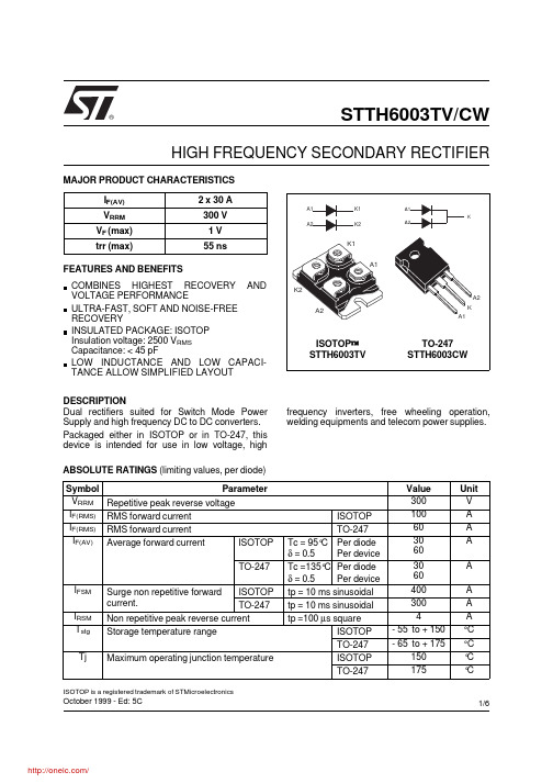
STTH6003TV/CWOctober 1999 - Ed: 5CHIGH FREQUENCY SECONDARY RECTIFIER®Dual rectifiers suited for Switch Mode Power Supply and high frequency DC to DC converters.Packaged either in ISOTOP or in TO-247, this device is intended for use in low voltage, high frequency inverters, free wheeling operation,welding equipments and telecom power supplies.DESCRIPTIONCOMBINES HIGHEST RECOVERY AND VOLTAGE PERFORMANCEULTRA-FAST, SOFT AND NOISE-FREE RECOVERYINSULATED PACKAGE: ISOTOP Insulation voltage: 2500 V RMS Capacitance: < 45 pFLOW INDUCTANCE AND LOW CAPACI-TANCE ALLOW SIMPLIFIED LAYOUT FEATURES AND BENEFITSSymbol ParameterValue Unit V RRM Repetitive peak reverse voltage 300V I F(RMS)RMS forward current ISOTOP 100A I F(RMS)RMS forward current TO-24760A I F(AV)Average forward current ISOTOPTc = 95°C δ = 0.5Per diode Per device 3060A TO-247Tc =135°C δ = 0.5Per diode Per device 3060A I FSM Surge non repetitive forward current.ISOTOP tp = 10 ms sinusoidal 400A TO-247tp = 10 ms sinusoidal 300A I RSMNon repetitive peak reverse current tp =100 µs square4A T stg Storage temperature rangeISOTOP - 55 to + 150°C TO-247- 65 to + 175°C TjMaximum operating junction temperatureISOTOP 150°C TO-247175°CABSOLUTE RATINGS (limiting values, per diode)I F(AV) 2 x 30 A V RRM 300 V V F (max) 1 V trr (max)55 nsMAJOR PRODUCT CHARACTERISTICSA1K1K2A2A1A2K1K2ISOTOP ™STTH6003TV ISOTOP is a registered trademark of STMicroelectronicsA1K A2A1A2KTO-247STTH6003CW1/6Symbol Parameter Tests conditionsMin.Typ.Max.Unit I R *Reverse leakage currentV R = 300 VTj = 25°C 60µATj = 125°C60600V F **Forward voltage dropI F = 30 ATj = 25°C 1.25V Tj = 125°C0.851Pulse test : * tp = 5 ms, δ < 2 % ** tp = 380 µs, δ < 2%To evaluate the maximum conduction losses use the following equation:P = 0.75 x I F(AV) + 0.008 x I F 2(RMS)STATIC ELECTRICAL CHARACTERISTICS (per diode)Symbol ParameterValue Unit R th (j-c)Junction to caseISOTOP Per diodeTotal 1.40.75°C/WTO-247Per diode Total 10.55R th (c)Coupling0.1When the diodes 1 and 2 are used simultaneously:∆Tj (diode 1) = P (diode 1) x R th(j-c) (per diode) + P (diode 2) x R th(C)THERMAL RESISTANCES Symbol Tests conditionsMin.Typ.Max.Unit trrI F = 0.5 A Irr = 0.25 A I R = 1A Tj = 25°C40nsI F= 1 A dI F /dt = - 50 A/µs V R = 30 V 55tfr I F = 30 A dI F /dt = 200 A/µs Tj = 25°C 350ns V FP V FR = 1.1 x V F max.5V S factor Vcc = 200 V I F = 30 A Tj = 125°C0.3-I RMdI F /dt = 200 A/µs11A RECOVERY CHARACTERISTICS STTH6003TV/CW2/65101520253035400510152025303540IF(av) (A)P1(W)Tδ=tp/Ttpδ= 1δ= 0.5δ= 0.2δ= 0.1δ= 0.05Fig. 1: Conduction losses versus average current (per diode).0.20.40.60.81.01.21.41.61.82.02.22.42.6110100VFM(V)IFM(A)Tj=125°C T ypical valuesTj=25°C Maximum valuesTj=125°C Maximum valuesFig. 2: Forward voltage drop versus forward current (maximum values , per diode).05010015020025030035040045050020406080100120140160180trr(ns)VR=200V Tj=125°CIF=2*IF(av)IF=IF(av)IF=0.5*IF(av)dIF/dt(A/µs)Fig. 5: Reverse recovery time versus dI F /dt (90%confidence, per diode).50100150200250300350400450500246810121416182022dIF/dt(A/µs)IRM(A)VR=200V Tj=125°CIF=2*IF(av)IF=IF(av)IF=0.5*IF(av)Fig. 4: Peak reverse recovery current versus dI F /dt (90% confidence, per diode).1E-31E-21E-11E+01E+10.00.20.40.60.81.0tp(s)Zth(j-c)/Rth(j-c)Tδ=tp/TtpSingle pulse δ= 0.5δ= 0.2δ= 0.1Fig. 3a: Relative variation of thermal impedance junction to case versus pulse duration (ISOTOP).1E-41E-31E-21E-11E+00.00.20.40.60.81.0Zth(j-c)/Rth(j-c)Tδ=tp/Ttptp(s)Single pulseδ= 0.5δ= 0.2δ= 0.1Fig. 3b: Relative variation of thermal impedance junction to case versus pulse duration (TO-247).STTH6003TV/CW3/62550751001250.00.20.40.60.81.01.21.41.61.82.02.22.4Tj(°C)IRMS factorFig. 7: Relative variation of dynamic parameters versus junction temperature (reference: Tj = 125°C).50100150200250300350400450500246810VFP(V)IF=IF(av)Tj=125°CdIF/dt(A/µs)Fig. 8: Transient peak forward voltage versus dI F /dt (90% confidence, per diode).050100150200250300350400450500100200300400500tfr(ns)IF=IF(av)VFR=1.1*VFmaxTj=125°CdIF/dt(A/µs)Fig. 9: Forward recovery time versus dI F /dt (90%confidence, per diode).0501001502002503003504004505000.00.10.20.30.40.50.6S factor VR=200V Tj=125°CdIF/dt(A/µs)Fig. 6: Softness factor (tb/ta) versus dI F /dt (typical values, per diode).STTH6003TV/CW4/6PACKAGE MECHANICAL DATA ISOTOPREF.DIMENSIONS Millimeters Inches Min.Max.Min.Max.A11.8012.200.4650.480 A18.909.100.3500.358 B7.88.200.3070.323 C0.750.850.0300.033 C2 1.95 2.050.0770.081 D37.8038.20 1.488 1.504 D131.5031.70 1.240 1.248 E25.1525.500.990 1.004 E123.8524.150.9390.951 E224.80 typ.0.976 typ.G14.9015.100.5870.594 G112.6012.800.4960.504 G2 3.50 4.300.1380.169 F 4.10 4.300.1610.169 F1 4.60 5.000.1810.197 P 4.00 4.300.1570.69P1 4.00 4.400.1570.173 S30.1030.30 1.185 1.193STTH6003TV/CW5/6Information furnished is believed to be accurate and reliable. However, STMicroelectronics assumes no responsibility for the consequences of use of such information nor for any infringement of patents or other rights of third parties which may result from its use. No license is granted by implication or otherwise under any patent or patent rights of STMicroelectronics. Specifications mentioned in this publication are subject to change without notice. This publication supersedes and replaces all information previously supplied.STMicroelectronics products are not authorized for use as critical components in life support devices or systems without express written ap-proval of STMicroelectronics.The ST logo is a registered trademark of STMicroelectronics © 1999 STMicroelectronics - Printed in Italy - All rights reserved.STMicroelectronics GROUP OF COMPANIESAustralia - Brazil - China - Finland - France - Germany - Hong Kong - India - Italy - Japan - MalaysiaMalta - Morocco - Singapore - Spain - Sweden - Switzerland - United Kingdom - U.S.A.PACKAGE MECHANICAL DATA TO-247F2F1V2L4L2L1L3DLL5MEHVVADia.F3F4G = =F(x3)REF.DIMENSIONSMillimeters Inches Min.Typ.Max.Min.Typ.Max.A 4.85 5.150.1910.203D 2.20 2.600.0860.102E 0.400.800.0150.031F 1.00 1.400.0390.055F1 3.000.118F2 2.000.078F3 2.00 2.400.0780.094F4 3.00 3.400.1180.133G 10.900.429H 15.4515.750.6080.620L 19.8520.150.7810.793L1 3.70 4.300.1450.169L218.500.728L314.2014.800.5590.582L434.60 1.362L5 5.500.216M 2.00 3.000.0780.118V 5°5°V260°60°Dia. 3.55 3.650.1390.143Ordering code Marking Package Weight Base qty Delivery modeSTTH6006TV1STTH6006TV ISOTOP 27gwithout screws10with screwsTubeSTTH6006CW STTH6006CW TO-247 4.36g30TubeCooling method: by conduction (C)Recommended torque value (ISOTOP): 1.3 N.m.Recommended torque value (TO-247°: 0.8 N.m.Maximum torque value (ISOTOP): 1.5 N.m.Maximum torque value (TO-247): 1.0 N.m.Epoxy meets UL 94,V0STTH6003TV/CW6/6分销商库存信息: STMSTTH6003CW。