MFC98多功能话务台用户手册V4.02
电话本说明书MFC大作业

电话簿软件说明书09计科A2 20113430110陈南博一、需求分析(功能说明)本软件拟实现以下功能:1.核对功能:要求进入电话簿的人必须是已注册的。
2.注册功能:注册新用户,使其能进入电话簿,有防止相同账号注册。
3.显示功能:能够显示所有编辑序号,添加时间,联系人,电话,邮箱,地址,QQ。
并且按照编辑序号升序排列,手动调整列宽。
4.添加功能:能够添加新的电话联系的记录信息,核对避免相同的联系人再次被记录。
5.删除功能:能够删除旧的电话联系的记录信息,更具添加信息条的时间作为删除依据。
6.刷新功能:能够对做出修改的电话簿进行刷新,显示最新的电话簿信息。
7.帮助记忆功能:根据选择的联系人,同时在窗口显示头像。
(未实现)。
二、设计说明书1.以access数据库为存储媒介,完成库工作。
具体如下:1.在进入电话簿前要求输入的账号密码与进入成员表核对。
2.注册成为电话簿成员,资料写入电话簿成员表3.进入电话簿后调用电话簿表,通过控件对数据库进行刷新,添加,删除工作4.建立数据库表格:表1:电话簿允许进入成员表表2:电话簿具体内容2.进入登陆框界面a.按退出则退出程序b.按注册一个新用户则跳对话框填写完整数据后注册,如果注册成功则提示如果已有账户则提示按返回按键则回到登陆界面。
c.登陆是账号密码错误时会提示d.3.成功登陆后则显示界面:之后则更具相应的按键做一些列操作。
按退出程序跳出退出程序对话框:特别制作有防伪Icon.三、代码实现1.由于整个程序都基于ADO操作ACCESS数据库,对于应用有很大方便,而对于程序编写增加了许多难度。
在编写时,它常常会有意想不到的错误需要灵活运用try{“这里是待测程序段”}catch(_e_error e) {AfxMessageBox( "此处编写出错地点提示!");return;} 这段语句结合断点测试,能准确定位错误地点,使我正确调试程序,如果运用的好,可以转变为程序所需的提示框。
飞越计算机话务台使用说明
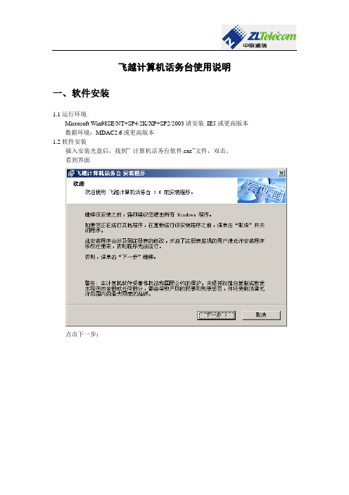
飞越计算机话务台使用说明一、软件安装1.1运行环境Microsoft Win98SE/NT+SP4/2K/XP+SP2/2003请安装IE5或更高版本数据环境:MDAC2.6或更高版本1.2软件安装插入安装光盘后,找到”计算机话务台软件.exe”文件,双击。
看到界面点击下一步:输入名称和公司后点击下一步选择一个安装路径,然后点击下一步:输入快捷方式文件夹的名称,然后点击下一步:点击下一步,等待安装程序拷贝文件,注册文件,然后会弹出一个对话框点击”是”安装SoapToolkit20。
注意:此工具在某些机器上安装时可能会等待较长时间才会弹出安装的界面来,所以在未弹出安装界面来之前请耐心等待。
到此,软件安装完毕。
二、软件使用2.1软件登录双击桌面的快捷方式:可看到登录界面如下图所示:输入服务器地址和用户名之后点击”登录”即可,在”设置”可改变端口号,默认为9600。
2.2软件结构1图2图3图功能使用:话务台只需用鼠标轻轻点击便可简单的实现拨号、闪断、挂断以及队列中来话的提取和保留。
2.3话机列表图标含义如下:此界面可显示设定内线分机的实时状态,当分机空闲时通过点击图标下方的“拨”按钮快速的实现对应内线分机的拨号;当分机振铃时通过点击图标下方的“代”按钮可实现对该分机来电的代接功能;当分机通话时分别通过点击图标下方的“拆、插、监”按钮可实现对该线路的拆线、插入以及监听功能。
当点击话机图标时即可显示此话机的详细信息,具体内容如下图所示:关于话机列表的话机是如何设置得来的,将在”话机设置” 中解释。
会有小红灯显示会有小绿灯显示2.4房态信息此界面用来设定话机对应房间的房态信息,房态的定义在“cti服务器”软件的“系统参数设置”中的”房态设定”中设置。
左侧的按钮会根据”房态设定”中定义的房态类型自动生成。
快速定位:在”快速定位”下方的文本框内输入电话号码,在本页内会定位至该号码所在的行并标记选中,此时点击左侧的按钮或者在第二列点击鼠标右键在弹出的房态菜单中选择想新设置的房态即可改变房态。
PC 话务台 使用说明

PC 话务台使用说明随着价格的下降,电脑已经得到了普及。
新开发的话务台软件,利用电脑的专用键盘快捷、直观地处理所有的话务操作,并监视话路使用状态,来去电号码,语音提示内外线来电等;界面美观、操作方便。
EI J K LOA 显示外线的地址序号B 外线显示状态区C 最后一次外线来电号码D 最后一次内线来电号码E 外线保留区F 内线显示切换G 内线状态显示窗口H 存储电话号码I 系统设置项J 最近的呼入记录 K 总机工作状态 L 内线保留区 M 呼叫号码N 内线显示状态选择O 拨号数字键与话务处理功能键本系统只对话务进行处理,交换机的参数设置、计费管理等请另外安装随机配光盘\PC-2000GL 管理系统。
号码设置:为保持系统号码与交换机一致,在‘号码设置’窗口,按‘导入’键,选择‘PC-2000GL管理系统’所在目录下的‘Main.mdb’数据库文件打开,系统自动取‘PC-2000GL’分机0组的号码。
在‘名称’、‘单键呼叫’栏设置对应分机的名称、和快捷呼叫单键。
电话薄:存储50个电话号码。
电话簿里可以设置常用的电话号码、名称以及快捷拨号单键。
当电话簿打开时,按单键呼叫存储的对应号码。
键盘功能定义与使用功能键各单键的具体功能如下:数字键:0、1……9跟话机数字拨号键一样,话务台为内外线转接拨号、呼叫拨号、或操作功能代码都使用数字键盘。
Esc:为退出系统键1页、2页……8页键:为内线翻页快捷键,每页显示128门分机的状态;显示内容有以下快捷键决定:Alt+“通1”键:为分机显示“状态”快捷键;Alt+“通2”键:为分机显示“序号”快捷键;Alt+“通3”键:为分机显示“名称”快捷键;Alt+“通4”键:为分机显示“号码”快捷键;Alt+“通5”键:为分机显示“单键”快捷键;Alt+“通6”键:为分机显示“状态+序号”快捷键;Alt+“通7”键:为分机显示“状态+号码”快捷键;Alt+“通8”键:为分机显示“状态+名称”快捷键;Alt+“通A”键:为分机显示“状态+单键”快捷键;Alt+“通B”键:为分机显示“序号+名称”快捷键;Alt+“通C”键:为分机显示“序号+号码”快捷键;Alt+“通D”键:为分机显示“序号+单键”快捷键;Alt+“通E”键:为分机显示“名称+号码”快捷键;Alt+“通F”键:为分机显示“名称+单键”快捷键;Alt+“外线”键:为分机显示“号码+单键”快捷键;静音键:当总机有内线或外线呼叫时,本系统会有不同的提示音来提示话务员,按一下静音键可关闭或开启该提示音。
MFC--CMQv系列使用说明

⊼ᛣ
⫼Ѣ⚻ఈⱘぎ➗↨ࠊⱘจড়ˈ䂟䀁㿜Ϟ㗗ᝂᇡㄪˈҹ䰆ℶಲ☿ⱘⱐ⫳ ेՓ⫷⫳њಲ☿гϡ᳗ᕅ䷓ᴀ″DŽ ⚻ఈܻⱘಲ☿᳗Փ䜡ㅵܻⱘວϞछ⫷⫳☿✄ˈᕲ㗠ᇢ㟈ᬙ䱰DŽ ᴀ″ϡ㛑⫼Ѣ⇿⇷ǃ⇺⇷ⱘ⁶␀ǃࠊDŽ⇿⇷ǃ⇺⇷Փ⫼ⱘจড়ˈ䂟⫼ᇖ⫼ ⱘⱘ⇿⇷ǃ⇺⇷ᇡឝൟDŽ 䂟ϡ㽕䅧ᓖ⠽⌕ܹᴀ″ܻDŽ䜡ㅵܻⱘ䢍ǃ∈Ⓢǃ⊍䳻ǃ♄้ㄝ⌕㍧ᴀ″ܻᰖˈ ᳗⫷⫳␀䞣ǃࠊ䁸Ꮒঞৃ㛑᧡າᴀ″DŽৃ㛑᳗᳝ᓖ⠽⌕ܹⱘจড়ˈ䂟ᴀ ″ⱘϞ⌕ˈو䀁㿜ৃ䰸এPҹϞᓖ⠽㛑ⱘ䘢◒㺱㕂ˈᑋ䘆㸠ᅮᳳ㎁ 䅋ঞDŽ 䂟ࢩᏂວ㆘ೡܻՓ⫼ᴀ″DŽˈϡ㽕ᮑࡴ䍙䘢㗤ວҹϞⱘວDŽ ৺ࠛৃ㛑᳗᧡າᴀ″DŽ ᴀ″ⱘ䭹ϡ᳝ᅠܼℶⱘ㛑DŽ䳔㽕ᅠܼℶⱘจড়ˈ䂟䚼䀁㿜 ᅝ㺱ߛᮋ䭹DŽˈ䚼ⱘߛᮋ䭹䮰䭝ᰖˈ䂟ᣝϟ㿬ⱘᮍ⊩ПϔˈࢭᖙՓ ᴀ″ⱘ䭹㰩Ѣܼ䭝ⱘᕙ″⢔ᜟ 噝 Փ䀁ᅮ⌕䞣⠆䳊 噝 Փ䭹㰩Ѣܼ䭝ᓣ ेՓ䚼ⱘߛᮋ䭹䮰䭝 ⌕䞣⠆䳊 ˈབᵰ䅧ᴀ″㰩Ѣ䗮ᐌࠊⱘ⢔ᜟˈ⭊ᠧ 䭟䚼ⱘℶ䭹ᰖˈ᳗ⶀ䭧⫷⫳䘢ⱘ⌕䞣DŽˈᇡ049 -. -. -. ˈ⭊㰩Ѣࠊᓣܼ䭟ᓣᰖˈབᵰ䚼ⱘߛᮋ䭹䮰䭝 ⢔ᜟᣕ㑠ߚ䧬ҹϞᰖˈ䭹䘢➅䰆ℶ䰤ᐙ $/ ᳗ࢩˈᔎࠊᇡ䭹侚ࢩ䳏⌕䘆 㸠䰤ࠊDŽ ᇡ6ZDJHORNǃ9&5䗷ൟˈ䂟⺎䁡ᇡឝⱘ䗷ӊᒴᆊⱘՓ⫼䁾ᯢ㿬䓝ⱘ⊼ ᛣџ䷙ᕠݡ䘆㸠䜡ㅵ䗷DŽ䳔Փ⫼䗷ӊᰖˈ䂟Փ⫼6ZDJHORN݀ৌⱘབ ϟ⫷કDŽ 6ZDJHORN ˖6667 ῭⑪ 66676& 火⊍ 6ZDJHORN ˖6667 ῭⑪ 66676& 火⊍ 9&5 ˖669&56& 9&5 ˖669&5676&Ⳍ⭊ક
ᅝܼϞⱘ⊼ᛣ
ᴀᅝܼ⊼ᛣџ䷙ⱘⳂⱘ˖⠆њℷ⺎ᅝܼՓ⫼ᴀ⫷કˈ䙓ܡ㌺ᙼঞҪҎ䗴៤Ҏ⫳᧡ᆇঞ 䉵⫷᧡༅ˈ䂟ϔᅮ䙉ᅜᴀᅝܼ⊼ᛣџ䷙DŽᴀЁՓ⫼њ。೪ൟヺ㰳ˈ݊㸼冫ⱘ㕽 བϟ᠔冫ˈ䂟䁡ⳳ⧚㾷᠔䗄ܻᆍ
杰尼奥电子D5000系列数字无线麦克风系统说明书

D5000 Series Digital Wireless Microphone SystemCOOKBOOKHeadset microphone WH-4000H WH-4000ATie-clip microphone YP-M5300YP-M5310Wireless antenna YW-4500Antenna distributor WD-5800Digital wireless transmitter WM-D5300 (belt-pack type)Digital wireless microphone WM-D5200 (handheld type)Battery charger BC-2000Rechargeable battery WB-2000-2SpeakerAmplifierDigital wireless receiverWT -D5800IndexSystem Equipment ConfigurationSystem Equipment Configuration How the Digital Wireless System Works Advantages of the Digital Wireless System Installation/Setting Procedures – One Room Installation/Setting Procedures – Multiple Rooms Installation of the YW-4500 Wireless Antenna Antenna Distribution Frequency T ableProcedure for Reusing the Same Frequency Encryption Function Settings Interference Countermeasures Antenna Attenuator FBS Setting EQ SettingOptimizing Sound Volume...1...2...3, 4...5...6...7...8, 9...10, 11, 12, 13...14, 15...16...17...18...19...20 (21)*BC-2000 and WB-2000-2 are not designed for the use in the U.S. and Canada, and available in these countries.**How the Digital Wireless System WorksSignal waveforms are used to represent sound, and the state of the sound is expressed according to the width or height of the waveform. Wireless microphones transduce the waveform of audio entering the microphone into an electrical signal and transmit that signal to a tuner over radio waves. In this event, it is an analog wireless system that processes the audio signal as it is in the waveform. On the other hand, it is a digital wireless system that digitally processes the audio signal.More specifically, in the digital system, after an analog signal (waveform) is transduced into a digital signal (asignal simplified by binary numbers 0 and 1) and transmitted by radio, the digital signal is demodulated into an analog signal and then the audio is output. By digitally processing and simplifying the audioinformation to be transmitted, the system can have a variety of advantages, including strong immunity to noise and maintenance of clear sound.Let’s have a look at the “D/U ratio” of analog-to-digital wireless systems. The D/U ratio refers to the ratio of the desired (D) signal to the undesired (U) signal (unit: dB). The desired signal represents the level of that signal, while the undesired signal represents the level of signal interference, otherwise called noise. The D/U ratio decreases as the undesired signal increases. The D/U ratio can be considered to be a value necessary to maintaining clear sound in a wireless system. If a comparison is made of the necessary D/U ratio between analog and digital wireless systems, it is 40dB for analog systems and 20dB for digital systems. From this, it can be seen that the digital wireless system has an edge over the analog wireless system by 20dB in terms of necessary D/U ratio, indicating that the digital system can maintain clear sound in circumstances where a lot of undesired signals are present.» How the Digital Wireless System Works» Why are digital wireless systems resistant to interference signals?Analog System Digital SystemDigital signal processing of analog audioDemodulation of digital to audible analog signal(analog)“H el l o ”Audio (analog)12Wireless receiverBroadcast122Not only can the digital wireless system reduce the influence of noise, it can also maintain clear sound quality by means of digital processing. In addition to this, there are various advantages unique to the digital wireless system.» Use of Multiple Channels in the Same AreaSince the wireless microphone makes itself a source of noise, when using multiple channels in the same area, channels must be arranged to avoid radio interference due to intermodulation interference. In the case of the analog wireless system, the most efficient channel arrangement is as shown in the [Analog] figure below if the intermodulation interference of radio waves is taken into consideration. In this arrangement, the simultaneous use of 6 channels is all it can handle per 4 MHz band.* This is an example.In the digital wireless system, however, since one of its features is being immune to the influence of noise, even when the intermodulation interference occurs, individual channels are less likely to be affected by it. As a result, equal-interval channel arrangements such as shown in the [Digital] figure below becomes possible, allowing up to 10 channels to be used simultaneously per 4 MHz band.* This is an example.» Interference Noise MutingAnalog systems are prone to generation of strange noises when exposed to radio interference. Conversely, radio interference is muted in digital systems, so strange noises are not produced.» Reuse of the Same ChannelAnother advantage of the digital wireless system is that simultaneous use of multiple microphones on the same frequency in the same area can be realized more easily because of its immunity to radio interference and noise.In the case of analog systems, the distance between microphones should be at least 100 meters when using the same frequency channel in the same area to ensure 40 dB of D/U ratio. However, in the case of digital systems, the distance can be reduced to 30 - 40 m*, making it easier to cope with even a building (area) with multiple rooms that require multiple microphones.*This can change depending on antenna mounting conditions or room conditions, such as the thickness or material of walls.Area and RoomRoomRoom» Improved SecurityConventional analog wireless systems transmit their audio signals through FM modulation. With this method, it is possible that communications could be intercepted by general broadband receivers (FM radio, etc.), causing much anxiety in terms of security. On the other hand, with digital systems, since the audio is transmitted through digital modulation, only noise can be heard if received by a broadband receiver. This can prevent exposure of information, leading to improvements in the security of information communication.(Horizontal coverage of antennas, Page 7)the supplied antenna.the supplied antenna.(Installation of the YW-4500 Wireless antenna, Page 7)o Step (3)(Antenna distribution, Page 8, 9)1) Select an arbitrary bank from Banks 1 – 4 at the receiver. (Frequency table, Page 10 -13) If you need more simultaneously usable channels, then use Bank A – F . In this case, please switch transmitter's T ransmission Output to "L (1mW)".* Banks A – F cannot be used when including existing analog wireless equipment in the system. 2) Check for idle channels using the channel scanning function.3) Similarly, perform bank settings and idle channel assignments for the remaining receivers.4) Set the transmitters for the same bank and frequency channels as the receivers.Perform encryption settings if it is necessary to prevent eavesdropping.(Encryption settings, Page 16)(Radio interference countermeasures, Page 17)(FBS settings, Page 19)(EQ Settings, Page 20)(7) Optimize the sound volume.(Sensitivity and volume settings, Page 21)Installation/Setting Procedures - One Room(1) Determine the operation range. (Horizontal coverage of antennas, Page 7)the supplied antenna. Use the supplied antenna.the supplied antenna. Use the YW-4500 external antenna.(Installation of the YW-4500 Wireless antenna, Page 7) (2) Determine the number of transmitters to use.o Step (3)(Antenna distribution, Page 8, 9)(3) Confirm the number of channels that can be simultaneouslyused by the frequency table. (Frequency table, Page 10 - 13)Page 14,15)1) Select an arbitrary bank from Banks 1 – 4 at the receiver. (Frequency table, Page 10 - 13)If you need more simultaneously usable channels, then use Bank A – F.In this case, please switch transmitter's T ransmission Output to "L (1mW)".* Banks A – F cannot be used when including existing analog wireless equipment in the system.2) Check for idle channels using the channel scanning function.3) Similarly, perform bank settings and idle channel assignments for the remaining receivers.4) Set the transmitters for the same bank and frequency channels as the receivers.Perform encryption settings if it is necessary to prevent eavesdropping. (Encryption settings, Page 16)(Radio interference countermeasures, Page 17)(8) Optimi sound quality.(FBS settings, Page 19)(EQ Settings, Page 20)(Sensitivity and volume settings, Page 21) Installation/Setting Procedures - Multiple RoomsPoint 1Mount the two antennas within 20 – 30m (outdoor applications: 40 – 50m) visible range from the microphone’s area of intended use.Both antennas should be within visible range from any location where the microphones are to be used. This is necessary for ensuring optimal conditions for one antenna to receive signals when the microphone my experience the other antenna's dead spot. In other words, the shape of the room does not matter provided that the above conditions are met. On a diagram of the site, use a compass to draw two circles representing a radius of 20 – 30m with each antenna as the central point. If usage locations fall within either of the two circles, such locations can be deemed to be okay.Point 2As a guideline, the distance between the two antennas should be 3 – 18m. Although the coverage area becomes wider as the distance between antennas increases, this degrades the diversity effect, and signal interruption will become more liable to occur.If possible, locate one antenna in the direction that can be viewed from the position where the microphone is held, and the other antenna in the opposite direction (behind the microphone holder).Point 3In indoor installations, as a general guideline, install antennas at a height of 2 – 4m above the floor, lest the signal be blocked by people in the room. Keep the antennas about 30cm below the ceiling. Install the antennas so they face in the specified directions. When making protectors, use resin or timber and do not use metallic materials.• Avoid positioning antennas close to metallic objects wherever possible.• Avoid mounting antennas inside a ceiling or wall.• Select locations where the antenna can be protected from being hit and damaged by objects.• Protect the antennas against rain water.Important points for selecting the mounting position of diversity antennas are as follows:Horizontal coverage of antennas under optimal conditionsInstallation of the YW-4500 Wireless Antenna• YW-4500• WT -D5800 Rod Antenna• Using 1 - 3 channelsAntennas can be distributed without using the WD-5800 Antenna Distributor.• Simultaneous use of 4 channels• Simultaneous use of 5 – 8 channelsaudio• Simultaneous use of 9 -16 channels• Simultaneous use of 17 - 32 channelsaudioto mixeraudioto mixeraudioto mixeraudioto mixeraudioto mixeraudioto mixeraudioto mixeraudioto mixeraudioto mixeraudioto mixeraudioto mixeraudioto mixerSplit antennas into two systems and construct a system of up to 32 channels.• Frequency table which can be used with 5000 Series analog wireless systemCompatible Frequency List*WM-D5200/D5300, WT-D5800: BANK 1 - 4WM-4200/4300/5220/5270/5320/5225/5265/5325: BANK 1– 4WT-4800/5800/5805: BANK 1– 4WM-4210/4220/4310, WT-4810/5100/5810, WTU-4800: BANK 1• When needing more channels*Banks A - F cannot be used when including existing analog wireless equipment in the system.Compatible Frequency List*WM-D5200/D5300, WT-D5800• Frequency table which can be used with 5000 Series analog wireless systemCompatible Frequency List*WM-D5200/D5300, WT-D5800: BANK 1 - 4WM-4200/4300/5220/5270/5320/5225/5265/5325: BANK 1– 4WT-4800/5800/5805: BANK 1– 4WM-4210/4220/4310, WT-4810/5100/5810, WTU-4800: BANK 1• When needing more channels*Banks A - F cannot be used when including existing analog wireless equipment in the system.*WM-D5200/D5300, WT-D5800• Frequency table which can be used with 5000 Series analog wireless system*WM-D5200/D5300, WT-D5800: BANK 1 - 4WM-4200/4300/5220/5270/5320/5225/5265/5325: BANK 1– 4WT-4800/5800/5805: BANK 1– 4WM-4210/4220/4310, WT-4810/5100/5810, WTU-4800: BANK 1• When needing more channels*Banks A - E cannot be used when including existing analog wireless equipment in the system.*WM-D5200/D5300, WT-D5800• Frequency table which can be used with 5000 Series analog wireless system*WM-D5200/D5300, WT-D5800: BANK 1 - 4WM-4200/4300/5220/5270/5320/5225/5265/5325: BANK 1– 4WT-4800/5800/5805: BANK 1– 4WM-4210/4220/4310, WT-4810/5100/5810, WTU-4800: BANK 1• When needing more channels*Banks A - E cannot be used when including existing analog wireless equipment in the system.*WM-D5200/D5300, WT-D5800When using transmitters in numbers greater than the number of simultaneously usable channels and in close proximity to each other, microphones operating on the same frequency can be used simultaneously by utilizing their digital characteristics. Note, however, that the same frequency cannot be used in the same room.1. Make channel plans1) Referring to the Frequency T able, select an arbitrary bank from A to F . 2) Scan receiver channels.• C band: Searches for channels in two banks including the currently-set bank and displays idle channels.Combinations of scanned banks are as follows: When Bank A or B is currently set a Searches for and displays idle channels in Banks A and B. When Bank C or D is currently set a Searches for and displays idle channels in Banks C and D.When Bank E or F is currently set a Searches for and displays idle channels in Banks E and F .• G band: Searches for all bank channels in the dedicated digital plan, and displays idle channels.3) Assign idle channels to multiple rooms as shown in the following examples to prevent channelsoperating on the same frequency from being too close to each other.[Example] Same floor or same location on each floor.[Example] Multiple rooms are adjacent to each other on both upper and lower floors in facilities like rental conference rooms and schools. There is a high possibility that the frequencies being used in the ‐ Keep channels using the same frequency as far away from each other as possible. If used on the same floor, keep them at least two rooms apart.‐ Set the wireless microphone’s transmission output to “L.”‐ Adjust the antenna attenuator.2. Use "Code" (recommended)This function prevents interference between channels sharing the same frequency. By performing Code settings, receivers and transmitters can be paired, muting radio signals on the same frequency that may exist in the surrounding area. Code setting is effective when the encryption function is not set.» Code setting proceduresFigure a. Even if the code is the same, if the power for both microphones is ON, radio interference will not occur. (Since the stronger radio signal takes precedence, only the microphone within the immediate area is reproduced.)Figure b. If power to either area is turned off when Figure a conditions exist, Receiver 1 may mistakenly receive MIC 2 audio. (Since the code is the same, it would be impossible to distinguish between MIC 1 and MIC 2.)Figure c. If different codes are set in Area 1 and Area 2, mistakenreception will not occur even if power to the microphone for either area is turned off. (Since microphones in both areas differ in code, audio is muted.)Code settingssolve these problems.Hold down the “SET” key for 2 seconds or more.Select “CODE” and press “SET”Select an arbitrary numberSet the same code for the transmitter to be paired.WT -D5800M E N U >C O D ES E T C O D ENOTE: Since the encryption function, which enhances security, also requires pairing of a transmitter with a receiver, code setting is unnecessary if the encryption function is used.Hold down the “SET” key for 2 seconds or more.Select ENCRYPTION from the menu Select “ON”Select P AIRING from the menu1) Enable receiver’s encryption function.2) Pair the receiver with a transmitter.Switch on the transmitter while holding down the “Encryption” setting switch.Press and hold “SET” till the “SUCCESS” is displayed.If encryption function is achieved, the“ANT A/B” indication and the lock icon lights red.If pairing is achieved, the “ANT A/B” indication lights green andthe transmitter’s “Encryption” light also lights.WT -D5800SETM E N U>H O L D T H E S E T K E YM E N U >PA I R I N GPA I RI N G P RO C E S S R E C E I V I N GPA I R I N G P RO C E S S S U C C E SSEncryption Function SettingsExposure of important information can be prevented by pairing a receiver with a transmitter by TOA’s proprietary security IDs.» Engryption setting proceduresInterference Countermeasures Order of Actions (Action Flowchart)Antenna Attenuator» Antenna Attenuator FunctionThis function decreases the antenna reception sensitivity so as to minimize reception of distant interference radio signals.•When to use this functionUse this function when radio interference or signal interruption caused by the interference of other systems intermittently occurs.Note: Since the use of an attenuator shortens the transmission distance and reduces the range of the usable area, ensure that the microphone can be used without signal interruption in the intended usage area after performing settings.The attenuator can effectively reduce interference signals if they are relatively weak. The most effective results may not be obtained when interference signals are strong (i.e. when audio interference constantly occurs).•Proper use of two attenuatorsUse either the WT -D5800 or YW-4500 attenuator to attenuate the reception sensitivity by 10dB. The WT -D5800 may be more convenient as it allows settings by hand.Since the attenuation of both the YW-4500 and WT-D5800 attenuators are added together, when wishing to attenuate reception sensitivity by at least 10dB, use both attenuators in combination.(This is a rare case, though.)UndesiredUndesiredFBS SettingIt is a function that the built-in feedback suppressor filter automatically works to suppress acoustic feedback when the feedback occurs.Use this function when increases in the receiving wireless microphone’s sound volume tend to generate acoustic feedback and reduce speech clarity or make it impossible to achieve the necessary sound volume for broadcast.» What is the feedback suppressor function?» What is the FBS built into the WT -D5800?NOTE: Acoustic feedback, or howling, is generated when sound output from a speaker reenters the microphone. Before using this function, check to see if the microphone and speaker are positioned too close to each other, or if the sound volume is louder than necessary.In circumstances where feedback is especially liable to occur, the most effective results may not be obtainable, or sound quality may vary greatly.LevelFeedback suppressor filterFrequencyFeedback frequencyHold down the “SET” key for 2 seconds or more.Select “FBS” and press “SET”WT -D5800M E N U >F B SS E T F B S 3O NEQ Setting (Recommended)This function optimizes audio characteristics for each model of handheld wireless microphone or any microphone connected to the belt-pack transmitter.Select the model number of the microphone to use, and perform settings in EQ setting mode.» What is the microphone EQ built into the WT -D5800?NOTE: This function is set to OFF by default.Set the “Microphone EQ” to OFF when the corresponding model number is not shown in the display of the EQ setting mode.Hold down the “SET” key for 2 seconds or more.OptionsWT-D5800S E T E Q P R E S E T 3E X I TS E T E Q P R E S E T 3Y P -M 5300S E T E Q P R E S E T 3W M -D 5200S E T E Q P R E S E T 3O F FS E T E Q P R E S E T 3Y P -M 5310S E T E Q P R E S E T 3W H -4000AS E T E Q P R E S E T 3W H -4000HM E N U>E Q P R E S E TOptimizing Sound Volume(1) Set the receiver’s volume control to the 2 o’clock position.For current TOA wireless receivers with the volume control located on the front panel, the 2 o’clock position (scale 7) is the volume control position that minimizes sound distortion until the maximum input sound pressure is applied to the microphone. From that position to the maximum volume position, a gain of approximately 10dB is made available as an allowance when turning up the volume.(2) Set the transmitter’s (microphone’s) sensitivity to “H” or “L ” depending on whether the volume is insufficient or noise is detected at normal sound volume, or if distortion is not noticeable when speaking in a loud voice.n to the maximum volume position, a gain of approximately 10dB is made available as an allowance when turning up the volume.(3) Adjust the input level of the amplifier or mixer to an appropriate sound volume for use under normal conditions.Microphone sensitivity can be set to "0 dB (H)" or "-10 dB (L)".TOA Corporationwww.toa.jp。
话务台指导书
中兴话务台指导书本文介绍中兴话务台的功能,安装,使用,及常见故障的处理,当话务台不能正常启动时,若U卡红灯亮时,首先用数字话机排除外线障碍,然后检查U 卡的驱动程序,必要时重装U卡驱动程序或换U卡;若U卡绿灯亮,表明U卡驱动程序正常,与服务器的通讯正常,检查终端数据配置是否被更改,必要时重装话务台的软件,对于其它的业务障碍可以参考话务台的使用和操作部分排除。
一、话务台的功能综合话务台包括标准话务台、简易话务台、语音话务台,根据用户的需要,可以单独配置,也可以组合配置。
1、标准话务台的功能:●可以对话务员权限进行管理●具有排队功能。
●可以实现转接、插入、监听、预占、再振铃、三方通话、保持呼叫、静音、二次发号、自动转移等。
●可以对业务组内用户设置闹醒、免打扰、夜服等补充业务。
●可以修改业务组内用户的属性,如呼入权限、呼出权限、新业务等。
●可以对业务组内用户实现立即计费。
●可以查询业务组内、长、短号码的对应关系。
2.简易话务台的功能:●具有排队功能。
●可以实现转接。
3.语音话务台的功能:●可以自动受理呼叫,提供语音提示。
●可以实现转接。
二、话务台的安装目前南京的中兴话务台都是ISDN U卡方式通信,它的安装分为ISDN通信系统安装,U卡安装,话务台软件安装,数据参数配置,在话务台出现故障时可以有选择的重新安装某一部分,安装程序一般保留在用户的终端的D盘或E盘上。
1、ISDN通信系统的安装●确保终端的计算机名符合“ZX+区号+局号+节点号”的命名规范,节点号范围为134~239。
如不符合,请修改。
●如果以前安装过通信系统,请先找到操作系统目录下的WIN_MGT.INI文件,将其改名或删除。
再检查●在版本安装盘的安装目录INSTALL\NTTCP\中执行COMSEUP.EXE。
出现下图所示界面,选择[后台维护终端]、[U接口远程维护终端]、U卡类型目前一般是PCI、[安装通信系统]。
ISDN方式通信系统安装●所示界面单击[下一步],出现所示界面,在此设置“有名节点”。
加工中心操作手册

目录目录 (1)第一章HANUC CNC2000I系统说明 (5)1.1系统简介 (5)1.1.1产品外观 (5)1.1.2适配驱动装置 (5)1.2操作设备 (6)1.2.1主控器部分 (7)1.2.2操作面板部分 (9)1.3系统介绍 (15)1.3.1系统界面 (15)1.3.2系统的工作模式 (18)第二章系统操作 (20)2.1文件功能 (20)2.1.1打开文件 (20)2.1.2保存文件 (22)2.1.3另存文件 (22)2.1.4删除文件 (24)2.1.5清空文件 (25)2.2手动操作 (26)2.2.1手动返回参考点 (26)2.2.2手动进给 (27)2.2.3手动连续进给 (27)2.2.4手动单步进给 (27)2.2.5手轮进给 (27)2.2.6手动进给倍率 (27)2.3MDI模式 (28)2.4自动运行 (29)2.4.1自动归中 (29)2.4.2进给速度倍率 (33)2.4.3程序的输入 (33)2.4.4启动.停止 (35)2.5试运行 (35)2.5.1实际机床运转方法 (35)2.5.2不移动机床观察其图形以及位置显示变化的方法 (36)2.6参数的显示与设定 (38)2.6.1系统参数 (38)2.6.2轴参数 (40)2.6.3主轴参数 (40)2.6.4对刀参数 (41)2.6.5输入配置 (41)2.6.6输出配置 (42)2.6.7锁机参数 (42)2.6.8T自定义 (43)2.6.9M自定义 (43)2.7.数据的显示与设定 (45)2.7.1偏置量 (45)2.7.2工作坐标系参数 (46)2.7.3刀具补偿 (47)2.8手动快捷操作 (48)2.8.1选停(M01) (48)2.8.2坐标跟踪 (48)2.8.3代码跟踪 (48)2.8.4设置手动速度 (48)2.8.5显示比例 (49)2.8.6加工复位 (49)2.8.7系统复位 (49)2.9.安全功能 (50)2.9.1程序锁 (50)2.9.2紧急停止 (50)第三章加工示例 (51)3.1系统上电 (52)3.2建立机械坐标系 (52)3.3输入加工程序 (54)3.4对刀 (55)3.5建立工件坐标系原点 (56)3.6自动归中 (56)3.7图形仿真与加工仿真 (60)3.8自动加工 (61)3.9自动运行过程中常见的操作 (62)3.9.1加工复位 (62)3.9.2加工中断不影响后续加工 (62)3.9.3急停 (63)第一章HANUC CNC2000i系统说明HANUC CNC2000i系统采用嵌入式PC结构,以DSP为核心实现全闭环控制。
DX1S数字程控用户交换机编程手册(J10与J12)V8.02
DX1S(J10/J12)数字程控用户交换机编程手册版本:V8.02目录1.简介 (1)1.1词汇表 (1)2.重要提示 (2)2.1独占编程模式 (2)2.2保存编程数据 (2)2.3编程过程换机停电 (2)2.4编程过程中话务台停电 (2)2.5丢失编程密码 (2)2.6不接收编程密码 (2)3.编程模式 (4)3.1进入编程模式 (4)3.2退出编程模式 (4)3.3打印编程数据 (4)4.编程命令 (5)4.1编程命令0 (5)4.2编程命令1 (5)4.3编程命令2和3 (5)4.3.1项目0:广播端口服务状态 (6)4.3.2项目1:两条中继会议状态 (6)4.3.3项目2:设置首位号反极状态 (6)4.3.4项目3:呼叫等待指示状态 (6)4.3.5项目4:忙音类型 (7)4.3.6项目5:回铃音类型 (7)4.3.7项目6:区别拨号音类型 (7)4.3.8项目7:证实音类型 (7)4.3.9项目8:呼叫等待音类型 (7)4.3.10项目9:入中继振铃类型 (8)4.3.11项目10:呼叫保留音乐类型 (8)4.3.12项目11:叫醒服务信息类型 (8)4.3.13项目12:拨号音超时时长 (8)4.3.14项目13:忙音超时时长 (8)4.3.15项目14:位间隔超时时长 (8)4.3.16项目15:无应答超时时长 (9)4.3.17项目16:振铃超时时长 (9)4.3.18项目17:直拨分机超时时长 (9)4.3.19项目18:回叫超时时长 (9)4.3.20项目19:呼叫保留时长 (9)4.3.21项目20:自动回叫振铃时长 (10)4.3.22项目21:最小拍叉时长 (10)4.3.23项目22:最大拍叉时长 (10)4.3.24项目23:门锁继电器接通时长 (10)4.3.25项目24:中继拨号断/续比 (11)4.3.26项目25:中继拍叉时长 (11)4.3.27项目26:双音多频信号时长......... 114.3.28项目27:双音多频信号位间隔时长.. 11 4.3.29项目28:中继拨号超时时长A . (11)4.3.30项目29:中继拨号超时时长B (12)4.3.31项目30:中继拨号超时时长A的位数. 12 4.3.32项目31:拨号暂停时长 (13)4.3.33项目32:入中继振铃超时时长 (13)4.3.34项目33:中继释放延时时长 (13)4.3.35项目34:缩位拨号呼叫限制 (13)4.3.36项目35:分机呼叫信息呼叫选择 (14)4.3.37项目36:分机呼叫信息延时时长 (14)4.3.38项目37:分机呼叫信息位数选择 (14)4.3.39项目38:分机位数 (14)4.3.40项目39:中继群接入码位数 (15)4.3.41项目40:话务员/初始中继群接入码15 4.3.42项目41:话务员分机 (15)4.3.43项目42:传真分机 (15)4.3.44项目43:双音多频收号器服务状态.. 16 4.3.45项目44:校正拍叉 (16)4.3.46项目45:无应答语音通知起始语音通道 (16)4.3.47项目46:无应答语音通知结束语音通道 (16)4.3.48项目47:中继无应答超时时长 (17)4.3.49项目48:直拨分机提示语起始语音通道 (17)4.3.50项目49:直拨分机提示语结束语音通道 (17)4.3.51项目50:缩位拨号接入码位数 (17)4.3.52项目51:中继~中继呼叫超时时长.. 18 4.3.53项目52:直拨分码控制 (18)4.3.54项目53:直拨分机转中继呼出 (18)4.3.55项目54:直拨分机时缩位拨号呼叫限制 (19)4.3.56项目55:中继~中继呼叫 (19)4.3.57项目56:部呼叫等待超时时长 (19)4.3.58项目57:话务台声音提示状态 (20)4.3.59项目58:呼出限制方案 (20)4.3.60项目59:电脑话务员等待时长 (21)4.3.61项目60:中继服务状态 (21)4.3.62项目61:中继拨号方式 (21)4.3.63项目62:反极性检测 (22)4.3.64项目63:日间服务中继类型 (22)4.3.65项目64:夜间服务中继类型 (23)4.3.66项目65:日间服务中继应答分机 (24)4.3.67项目66:夜间服务中继应答分机 (24)4.3.68项目67:中继群拨号插入 (24)4.3.69项目68:中继接入码插入 (25)4.3.70项目69:呼叫结束标志 (25)4.3.71项目70:直拨分机数字7应答分机 (26)4.3.72项目71:直拨分机数字8应答分机 (26)4.3.73项目72:直拨分机数字9应答分机 (26)4.3.74项目73:双音多频信号转发状态 (26)4.3.75项目74:中继分机呼叫信息输出状态. 27 4.3.76项目75:屏蔽二次拨号音 (27)4.3.77项目76:主叫通道 (27)4.3.78项目77:选择直拨分机提示语通道 (28)4.3.79项目80:用户服务状态 (28)4.3.80项目81:用户拨号方式 (28)4.3.81项目82:用户类型 (29)4.3.82项目83:用户拨号等级—日服/入住. 29 4.3.83项目84:用户拨号等级—夜服/退房. 30 4.3.84项目85:用户功能等级—日服/入住. 30 4.3.85项目86:用户功能等级—夜服/退房. 30 4.3.86项目87:分机分配 (31)4.3.87项目88:用户初始中继群 (31)4.3.88项目89:PCM虚拟分机号 (31)4.3.89项目90:用户直线中继号 (31)4.3.90项目91:PCM虚拟局号 (32)4.3.91项目92:部呼叫等待状态 (32)4.3.92项目93:拨号音状态 (32)4.3.93项目94:转移呼叫-等待状态 (33)4.3.94项目95:被叫屏蔽状态 (33)4.3.95项目96:仅有快速拍叉 (33)4.3.96项目97:设定不同的用户给予不同的区号 (33)4.3.97项目100:国际长途呼叫字冠表 (34)4.3.98项目101:国长途呼叫字冠表 (34)4.3.99项目102:特服路由表 (34)4.3.100项目103:出中继字冠表ACT 3 (34)4.3.101项目104:出中继字冠表ACT 4 (35)4.3.102项目105:出中继字冠表ACT 5 (35)4.3.103项目106:出中继字冠表ACT 7 (35)4.3.104项目107:计费拨号等级 (36)4.3.105项目108:计费密码分配/强制接入码. 36 4.3.106项目109:系统密码分配 (36)4.3.107项目110:话务台服务状态 (37)4.3.108项目111:话务台分机 (37)4.3.109项目112:酒店服务应答分机 (38)4.3.110项目113:中继群起始中继号 (38)4.3.111项目114:中继群结束中继号 (38)4.3.112项目115:连选群分机 (39)4.3.113项目116:连选类型 (39)4.3.114项目117:连选群用户 (40)4.3.115项目118:功能等级分配 (40)4.3.116项目119:组网连选群.............. 424.3.117项目120:信号音电平. (42)4.3.118项目121:分机~分机传输增益 (43)4.3.119项目122:中继~分机传输增益 (43)4.3.120项目123:中继~中继传输增益 (43)4.3.121项目124:系统自动软复位 (43)4.3.122项目125:中继群呼出限制状态 (44)4.3.123项目126:E/M传输增益 (44)4.3.124项目127:E/M发号暂停时长 (44)4.3.125项目128:E/M瞬闪信号时长 (44)4.3.126项目129:E/M信号超时时长 (44)4.3.127项目130:PCM传输增益 (45)4.3.128项目132:PCM/EXP服务状态 (45)4.3.129项目133:编号方案 (45)4.3.130项目134:第一位拨号数字类型 (45)4.3.131项目135:电脑话务员数字类型 (46)4.3.132项目136:弹性位数 (47)4.3.133项目137:弹性编号起始 (47)4.3.134项目138:弹性编号结束 (48)4.3.135项目139:被叫屏蔽位数 (48)4.3.136项目140:PCM中继被叫屏蔽位数...... (48)4.3.137项目141:话务台显示模式 (49)4.3.138项目142:直拨分机无应答拆线 (49)4.3.139项目143:转移呼叫无应答拆线 (50)4.3.140项目144:语音信箱分机 (50)4.3.141项目145:信息等待振铃间隔时长 (50)4.3.142项目146:语音信箱应答超时时长 (50)4.3.143项目147:PCM出中继字冠 (50)4.3.144项目148:计帐功能超时时长 (51)4.3.145项目149:通话时长限制 (51)4.3.146项目150:弹性编号部呼叫删除位数 ... (51)4.3.147项目151:当前模块号/网管模块号.. 51 4.3.148项目152:模块部起始分机 (51)4.3.149项目153:模块部结束分机 (52)4.3.150项目154:模块连接主路由 (52)4.3.151项目155:模块连接第二路由 (52)4.3.152项目156:模块中继群主路由 (52)4.3.153项目157:模块中继群第二路由 (53)4.3.154项目158:PCM时隙呼叫方向 (53)4.3.155项目159:系统选项 (53)4.3.156项目160:中继群连选方式 (53)4.3.157项目161:自动切换到日服 (54)4.3.158项目162:自动切换到夜服 (54)4.3.159项目163:中继群接入码插入状态 (54)4.3.160项目164:长途呼叫时长限制 (54)4.3.161项目165:PCM+数据板占用时隙数 (55)4.4编程命令4和43 (55)4.5编程命令5和53 (56)4.6编程命令6和7 (56)4.6.1编程数据6和7补充部分 (57)4.7编程命令8 (66)4.8编程命令87 (67)4.9编程命令108 (67)5.J10软件特有编程命令 (68)5.1.1项目23:ETT2 专线摘机时间 (68)5.1.2项目75:PCM出呼叫送假二次拨号音.. 68 5.1.3项目82:ETT2用户类型 (68)5.1.4项目92:ETT2用户占用专线时电信中继线处理 (69)5.1.5项目102:特服路由表 (69)5.1.6项目104:特服限制表 (69)5.1.7项目107:长途路由表/计费拨号等....级 (699)5.1.8项目118:功能等级分配 (70)6.VMC、VPR软件特有编程命令 (71)6.1项目1:网管时隙 (71)6.2项目131:MFC记发器服务状态 (71)7.WAB无线中继板编程 (72)7.1路由号长表 (72)7.2连接操作 (72)7.3设置命令 (72)7.3.1进入设置模式命令 (72)7.3.2初始化数据命令 (73)7.3.3增加或修改路由号长命令*9: (73)7.3.4清除路由号长表命令 (73)7.3.5设置本地区号 (73)7.3.6删除本地区号 (73)7.3.7国际长途IP接入号 (73)7.3.8删除国际长途IP接入号 (74)7.3.9国长途IP接入号 (74)7.3.10删除国长途IP接入号 (74)7.3.11设置是否接听来话 (74)7.3.12设置是否锁机 (74)7.3.13设置来话是否计费 (75)7.3.14设置是否锁卡 (75)7.3.15设置锁小区功能 (75)7.3.16设置锁网功能 (75)7.3.17删除锁网 (75)7.3.18设置是否去掉013XXXX前面的“0” (75)7.3.19设置是否来电显示 (76)7.3.20是否禁拨其它段 (76)7.3.21设置禁拨段 (76)7.3.22单个删除禁拨段 (76)7.3.23全部删除禁拨段 (76)7.3.24设置免费段 (76)7.3.25单个删除免费段 (77)7.3.26全部删除免费段................... 777.3.27设置直拨段. (77)7.3.28单个删除直拨段 (77)7.3.29全部删除直拨段 (77)7.3.30设置加拨本地区号的段 (77)7.3.31单个删除加拨本地区号的段 (78)7.3.32全部删除加拨本地区号的段 (78)7.3.33设置国长途 (78)7.3.34单个删除国长途 (78)7.3.35全部删除国长途 (78)7.3.36音量大小调节 (78)7.4参数设置注意事项 (79)图图4-1中继拨号超时时长A、B (12)1.简介DX1S数字程控交换系统硬件安装完成后,应通过MFC98多功能话务台输入编程数据,以满足客户的要求。
- 1、下载文档前请自行甄别文档内容的完整性,平台不提供额外的编辑、内容补充、找答案等附加服务。
- 2、"仅部分预览"的文档,不可在线预览部分如存在完整性等问题,可反馈申请退款(可完整预览的文档不适用该条件!)。
- 3、如文档侵犯您的权益,请联系客服反馈,我们会尽快为您处理(人工客服工作时间:9:00-18:30)。
MFC98 多功能话务台用户手册版本:V4.02目录1.概述 (1)2.话务台硬件 (2)2.1LAN连接方式与设置 (2)2.2RS-232连接方式与设置 (5)2.3CAT连接方式与设置 (6)2.4MFC98卡连接方式与设置 (6)3.话务台软件 (8)3.1安装 (8)3.2使用 (8)4.话务台模式 (9)4.1话务台显示 (9)4.2话务处理 (11)4.3服务设定 (12)4.4其他功能 (13)4.4.1自定义按钮 (13)4.4.2编辑用户名 (14)4.4.3显示通话双方 (14)4.4.4电话簿 (14)4.4.5进入寻呼界面 (15)4.4.6进入多方会议 (16)4.4.7话务台键盘 (16)5.设置模式 (18)6.管理模式 (19)7.编程模式 (20)7.1系统参数 (20)7.1.1系统自动存档 (21)7.1.2系统自动软复位自动软复位 (21)7.1.3显示系统版本和时钟 (21)7.1.4设置系统时间 (22)7.1.5日服/夜服自动转换 (22)7.2编程数据 (22)7.2.1用户数据 (23)7.2.2连续分配分机号码 (24)7.2.3间隔分配分机号码 (25)7.2.4中继数据 (25)7.2.5E/M中继 (27)7.2.6PCM/PRI中继 (27)7.2.7信号音 (29)7.2.8定时器 (30)7.2.9资源服务状态 (31)7.2.10长途字冠表 (32)7.2.11其它 ...................................................... 337.3高级功能.. (34)7.3.1计费号码拨号等级和密码 (35)7.3.2系统密码分配 (35)7.3.3缩位拨号 (35)7.3.4话务台服务状态和分机 (36)7.3.5酒店服务应答分机 (36)7.3.6中继群编程 (37)7.3.7连选群编程 (38)7.3.8功能等级分配 (38)7.3.9计费密码随机分配 (39)7.3.10信号音电平 (39)7.3.11拆线 (40)7.3.12留言信息 (40)7.3.13系统选项 (40)7.3.14编号方案 (41)8.诊断模式 (44)8.1诊断模式菜单 (44)9.话单输出模式 (46)10.MFCTOOLS工具软件 (47)10.1通信设置 (47)10.2通信监控 (47)10.3接收监视 (48)10.4发送监视 (49)10.5上载下载 (49)10.6PRI监控 (50)图图2-1以太网连接方式 (2)图2-2连接设置 (3)图2-3MCC V3板卡参数设置 (3)图2-4硬件ID及话务台IP (4)图2-5话务台设置 (4)图2-6RS-232连接方式 (5)图2-7连接设置 (5)图2-8CA T连接方式 (6)图2-9MFC98卡连接方式 (6)图4-1话务台模式屏幕显示 (9)图4-2简化管理模式 (12)图4-3按钮自定义对话框 (13)图4-4电话号码簿 (14)图4-5振铃监视 (15)图4-6多方会议 (16)图5-1设置模式 (18)图6-1管理模式 (19)图7-1编程模式 (20)图7-2系统参数菜单 (20)图7-3系统自动存档 (21)图7-4系统自动软复位 (21)图7-5系统版本和时钟 (21)图7-6设置系统时间 (22)图7-7日服/夜服自动转换 (22)图7-8编程数据菜单 (23)图7-9用户数据 (23)图7-10连续分配分机号码 (24)图7-11间隔分配分机号码 (25)图7-12中继数据 (25)图7-13E/M中继 (27)图7-14PCM/PRI中继 (27)图7-15PCM中继服务状态 (28)图7-16MFC记发器服务状态 (28)图7-17信号音 (29)图7-18定时器 (30)图7-19资源服务状态 (31)图7-20长途字冠表 (32)图7-21其它 (33)图7-22高级功能菜单 (34)图7-23计费号码拨号等级和密码 (35)图7-24系统密码分配 (35)图7-25缩位拨号 (35)图7-26话务台服务状态和分机 (36)图7-27酒店服务应答分机 (36)图7-28中继群编程 (37)图7-29连选群编程 (38)图7-30功能等级分配 (38)图7-31计费密码随机分配 (39)图7-32信号音电平 (39)图7-33拆线 (40)图7-34留言信息 (40)图7-35系统选项 (41)图7-36编号方案 (41)图7-37数字类型 (42)图7-38弹性编号 (42)图8-1诊断模式 (44)图9-1话单模式 (46)图10-1通信设置 (47)图10-2通信监控 (48)图10-3接收监视 (49)图10-4发送监视 (49)图10-5上载下载 (50)图10-6PRI监控 (50)表表3-1话务台配置文件SETUP.INI (8)表4-1话务台模式屏幕显示............................... 11表4-2简化管理模式的操作 (13)表4-3话务台模式键盘操作 (17)表5-1设置模式 (18)1.概述MFC98多功能话务台是指与DX1S数字程控交换机配套的,集话务台功能、管理功能、维护功能(编程、诊断及监控)、话单输出功能于一体的终端。
在DX1S数字程控交换系统1个模块内,最多可有16个MFC98多功能话务台同时工作。
●话务台功能应答与转移呼叫、插入、监听、强拆、系统时钟与工作状态显示、中继/用户忙闲显示、呼叫处理信息显示以及电话会议功能。
●管理功能设置和取消用户的免打扰、离位转移、遇忙和无应答转移、叫醒服务、入住/退房、留言信息等待。
●维护功能设置和修改系统参数、用户参数、中继参数、信号音参数、时限参数、其它参数,监测通信数据,测试用户电路、中继电路、双音多频接收器、数字交换网络、电话会议电路、测试语音卡等。
须注意每个模块只能有一个话务台处在维护状态(编程或诊断状态)。
●话单输出功能DX1S数字交换机每模块内部存储6630条话单,需要时MFC98多功能话务台提取DX1S内部的话单,经RS232接口或并行打印口输出到计费系统、打印机或存为磁盘文件。
●传呼功能配置小传呼系统与DX1S数字交换系统配合,可实现自动寻呼,用户配带寻呼机,将寻呼机号码与用户号码对应,该用户分机振铃同时寻呼机响,DX1S配有主叫号码显示功能时寻呼机同时显示主叫号码,外线接转的呼叫显示外线号码。
本手册包括如下部分:●概述●话务台硬件●话务台软件●话务台模式●设置模式●管理模式●编程模式●诊断模式●话单输出模式●MFCTOOLS工具软件2. 话务台硬件在同一个DX1S 系统中最多连接16个MFC98多功能话务台,每个话务台均独立工作,用0~15话务台标示号加以区别。
MFC98话务台连接方式有4种类型:LAN 、CA T 、RS-232、MFC98卡。
2.1 LAN 连接方式与设置DX1SLAN以太网话务台(1)话务台(X )图 2-1 以太网连接方式硬件配置: ● DX1S 交换机需使用MCC V3主控板和TIM 以太网接口卡。
●话务台电脑最低配置:赛扬2 -700CPU 、128M 内存、2G 硬盘空余空间、光驱、VGA 彩显、101 键盘、鼠标、10M/100M 网卡、COM1、LPT1、Win98 / Win2000 / WinXP 操作系统。
● 话务台:MFC98 V4.05以上版本、话务台电话。
● 超五类交叉网线 或 直通网线。
连接方法: ● 用超五类“交叉网线”直接连接PC 网卡与MCC V3的LAN 接口; 或 用“直通网线”连接 HUB / Switch 后再与DX1S 相连。
通信设置: ● MFC98话务台模式下,按“F1”键,弹出‘连接设置’窗口,选择连接方式为“以太网”。
●输入“MCC V3 IP ”地址与端口(默认IP 为192.168.0.159,端口5001),点“打开”,如下图所示:图2-2 连接设置●以太网参数设置:在话务台模式下,按“F3”键,输入工号:001,输入密码:519,进入MCCV3板卡参数设置窗口。
选择硬件ID(默认为2),输入话务台IP为PC 的IP地址,点“设置”。
如下图所示:(本窗口下可以修改MCC V3的IP地址、掩码等,点设置后生效,请记住修改后的IP地址。
)图2-3 MCC V3板卡参数设置●点击‘查看’,确认硬件ID及话务台IP,如下图:图2-4 硬件ID及话务台IP注意:1)正常情况下“话务台IP”项全为:255.255.255.255,“话务台IP端口”全为65535,表示所对应的“硬件ID”没有启用。
2)每一台计算机IP地址对应一个“硬件ID”号,话务台IP不能重复。
3)“硬件ID”0~15是否允许使用,由编程项目110项定义(可参见《DX1S数字程控用户交换机编程手册》)。
设置话务台启动时的标示号:在话务台模式下,按“F6”键,输入密码(初始值:9856),进入设置模式。
选择“话务台标识号”为上述设定的“硬件ID”,点击“存盘退出”并重新启动话务台后有效。
图2-5 话务台设置注意:同一DX1S系统内最多允许16个话务台同时操作,每一个话务台都有一个不同的话务台标识号,如果有两个话务台标识号相同,将引起混乱。
2.2 RS-232连接方式与设置DX1SRS-232接口PC 串口话务台图 2-6 RS-232连接方式硬件配置: ● DX1S 交换机需使用MCC V3主控板。
(或 MCC+主控板配上NMC-LC 网管卡) ●话务台电脑最低配置:赛扬2 -700CPU 、128M 内存、2G 硬盘空余空间、光驱、VGA 彩显、101 键盘、鼠标、COM1、LPT1、Win98 / Win2000 / WinXP 操作系统。
● 话务台:MFC98 V4.05以上版本、话务台电话。
● RS-232维护电缆连接方法: ● 用“RS-232维护电缆”连接PC 的COM 口与MCC V3的RS-232接口。
通信设置: ● MFC98话务台模式下,按“F1”键,弹出‘连接设置’窗口,选择连接方式为“串口方式”。
COM 口、波特率为br9600,点“打开”,如下图所示:图 2-7 连接设置2.3 CAT 连接方式与设置CATDX1S话务台图 2-8 CAT 连接方式硬件配置: ● DX1S 交换机需使用VMC 主控板。
(或 MCC+主控板配上NMC-LC 网管卡) ●话务台电脑最低配置:赛扬2 -700CPU 、128M 内存、2G 硬盘空余空间、光驱、VGA 彩显、101 键盘、鼠标、COM1、LPT1、Win98 / Win2000 / WinXP 操作系统。