595D475X-010T2T中文资料
AD595
介绍了基于单片机的移动式温度数据采集仪的硬件设计,串行红外接口的应用及用可视化编程工具VB6.0实现的WINDOWS界面的数据接收、处理软件。
关键词热电耦温度测量数据采集红外串口通信在电子工业中,随着整机集成度的提高和元器件的微型化、复杂化,在印制板上焊接元件时对各种焊接设备波峰焊、回流焊、SMT 等内的温度工艺要求越来越高。
这就需要一种可移动的温度数据采集仪器,能随传送带进入焊炉内,测量记录下不同焊点印制板上的焊盘孔、过孔等在焊炉内不同位置时的温度参数,并能将测量数据方便地传送给电脑,进行数据曲线的显示、分析和打印,以便制定和执行合适的工艺流程。
无线通信可以去除设备对线缆和连接器的依赖。
IrDA红外通信是一种低价且适应性广的短距离无线通信技术,只要通信双方都支持IrDA 协议,就能很快建立通信链路,实现数据交换。
近来红外通信在电子设备中得到了广泛的应用。
为此,研制了带有红外接口的移动式温度数据采集仪。
该仪器由可充电电池供电,以1Hz的采集率同时对≤8的温度测量点采集600s的数据。
温度测量范围为0℃~300℃,测量精度为满量程的1%。
测量数据存于E2PROM中,可掉电保存,直到下次采集将数据更新。
通过串行红外接口,仪器可将存储的测量数据方便地传送给电脑。
用可视化编程工具Visual Basic6.0制作了Windows界面的数据接收和处理软件,既方便硬件间的连接又便于测量数据的输出与分析。
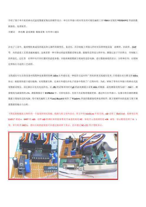
下图是我根据此文制作的一个温度控制实验板。
线路与原文有些改动。
原文中的MAX144不易买到。
AD改用了TLC2543,基准电压用LM317调成4。
096V给AD,这样AD检测出来的值如果是全0温度就是0C。
如是全1温度刚好是409。
6度。
显示精度达到了0。
1度。
单片机用89C51。
感应出来的温度值可以通过液晶屏上显示,也可通过RS-232用计算机显示。
1 采集仪的硬件原理仪器的硬件设计贯彻了确保性能、缩小外形(特别是高度要求苛刻)、便于移动、降低功耗和机内隔热的原则。
595组件参数

595组件参数595组件是一款常用的数字显示集成电路,常见于各类电子设备中。
本文将详细介绍595组件的参数及其相关知识,以帮助读者更好地了解和应用该组件。
二、595组件的功能特性1. 595组件采用串行输入并行输出的工作方式,能够将串行输入的数据通过移位寄存器存储,并同时控制并行输出的数据。
2. 595组件具有可控的输出电平,可用于控制LED灯、数码管等显示器件。
3. 595组件支持级联连接,多个595组件可以通过串行输出和并行输入进行级联,实现更多的输出通路。
三、595组件的电气参数1. 工作电压:595组件的工作电压范围为3.3V至5V,可根据实际需求选择适当的电压。
2. 静态工作电流:595组件的静态工作电流一般在2mA以下,通过合理的设计和控制可降低功耗。
3. 工作温度:595组件的正常工作温度范围为-40°C至85°C,适用于各种环境条件。
四、595组件的引脚定义1. VCC:供电正极,接入工作电压。
2. GND:地线,接入公共地线。
3. SER(Serial data input):串行数据输入,用于接收外部数据。
4. SRCLK(Shift register clock input):移位寄存器时钟输入,控制移位操作。
5. RCLK(Register clock input):存储器时钟输入,控制存储操作。
6. OE(Output enable input):输出使能输入,控制输出开关。
7. SRCLR (Serial data clear input):串行数据清零输入,用于清除移位寄存器中的数据。
8. Q0-Q7(Parallel output):并行数据输出,将存储在移位寄存器中的数据输出。
五、595组件的使用注意事项1. 在使用595组件时,应确保输入信号的稳定性和准确性,避免产生误操作。
2. 正确连接电源和地线,避免电路短路或过载现象。
3. 根据实际需要设置输出使能和存储器时钟输入,以控制输出数据的刷新和保持。
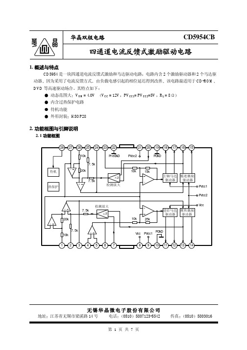
CD595
-50 0 50
3.6 4.0
13.5 15.5 17.5
0
1
2
待机工作电流 待机工作电压 待机关断电压
IST VSTON VSTOFF
0.5
0
0.5
2.0
单位
mA
mA V A/V
V
mA V mA mA mV V dB
mV V dB dB
mA V V
第3页共7页
华晶双极电路
4. 测试线路
CD5954CB
相位 (deg)
第5页共7页
华晶双极电路
6. 应用线路与应用说明
6. 1 应用线路
DSP
CD5954CB
u- COM
进给 聚焦 循迹 偏压 待机 主轴
100pF
28 27 26 25 24 23 22
10k
待机 热保护
7.5k 20k
7.5k
2 检测放大
7.5k
检测放大 2
20k
7.5k 10k
1234567
8 4
2
1
0
-1
-2
-3
-4
-5
-2 -1 0
1
2
输入电压 V IN (V)
进给驱动器前级运放频率特性
10k
60
+
180
-
20k
40
90
g
100
Vin
20
0
0
Vcc=12V, -20 PVcc1=
PVcc2=5V
10k
ห้องสมุดไป่ตู้
100k
1M
频率 f (Hz)
-90 -180 10M
奥德维特说明书

PDA 系列产品的设计、制造、检查、试验及特性都应遵照适合的最新版IEC 和中国GB 标准及国际单位SI 制。
GB/T13730《地区电网数据采集与监控系统通用技术条件》GB/50171-92《电气装置安装工作盘、柜及二次回路接线施工及验收规范》DL/T630《交流采样远动终端通用技术条件》DL/478-92《静态继电保护及安全自动装置通用技术条件》GB/50062-92《电力装置的继电保护和自动装置设计规范》GB/T50063-2008《电力装置的电测量仪表装置设计规范》DL/T587-1996《微机继电保护装置运行管理规程》GB/T13729-2002《远动终端通用技术条件》GB/14285-93《继电保护和安全自动装置技术规程》GB/T17626.12-1998《振荡波抗扰度试验》GB/T17626.11-2008《电压暂降、短时中断和电压变化抗扰度试验》GB/T17626.10-1998《阻尼振荡磁场抗扰度试验》GB/T17626.8-2006《工频磁场的抗扰度试验》GB/T17626.6-2008《射频场感应的传导骚扰抗扰度》GB/T17626.5-2008《浪涌(冲击)抗扰度试验》GB/T17626.4-2008《电快速瞬变脉冲群抗扰度试验》GB/T17626.2-2006《静电放电抗扰度试验》GB/T 14047-1993《量度继电器和保护装置》GB 3836.3-2000《爆炸性气体环境用电气设备 第 3 部 分:增安型"e"》JB/T 10613-2006《数字式电动机综合保护装置》GB/T13850-1998《交流电量转换为模拟量或数字信号的电测量变送器》JJG596-1999《电子式电能表检定规程》GB/T17215.321-2008《静止式有功电能表(1级和2级)》GB/T 22264-2008《安装式数字显示电测量仪表》产品标准Contents 目 录A -01综合电力监控仪PDA-120系列B -13 三相智能型电力仪表 PDA-103系列C -31单相智能型电力仪表 PDA-101系列D -51 智能型电动机保护控制器 PDA-110MRK F -66参考设计图附录产品业绩G -73GB/T17215.322-2008《》静止式有功电能表(0.2S 级和0.5S 级)E -58 低压电动机保护装置 ADVP-1451产品简介功能详表产品特点PDA -120系列综合电力监控仪是北京奥德威特电力科技股份有限公司按IEC 国际标准开发,与当今国际先进技术同步的网络化综合电力监控仪表。
595芯片资料

595
8位串行输入/输出或者并行输出移位寄存器,具有高阻关断状态。
三态。
特点:
8位串行输入
8位串行或并行输出
存储状态寄存器,三种状态
输出寄存器可以直接清除
100MHz的移位频率
输出能力:
并行输出,总线驱动
串行输出;标准
中等规模集成电路
应用:
串行到并行的数据转换
Remote control holding register.
描述:
595是硅结构的CMOS器件
兼容低电压TTL电路,遵守JEDEC标准。
595是具有8位移位寄存器和一个存储器,三态输出功能。
移位寄存器和存储器是分别的时钟。
数据在SCHcp的上升沿输入,在STcp的上升沿进入的存储寄存器中去。
如果两个时钟连在一起,则移位寄存器总是比存储寄存器早一个脉冲。
移位寄存器有一个串行移位输入(Ds),和一个串行输出(Q7’),和一个异步的低电平复位,存储寄存器有一个并行8位的,具备三态的总线输出,当使能O E时(为低电平),存储寄存器的数据输出到总线。
数据描述:
C PD决定动态的能耗
P D=C PD×V CC×f1+∑(C L×V CC2×f0)
F1=输入频率,C L=输出电容f0=输出频率(MHz)Vcc=电源电压
引脚说明:
功能表:
L=低电平状态
↑=上升沿
↓=下降沿
Z=高阻
NC=无变化
×=无效
当MR为高电平,OE为低电平时,数据在SH CP上升沿进入移位寄存器,在ST CP上升沿输出到并行端口。
74LS595中文资料

PACKAGING INFORMATIONOrderable Device Status(1)PackageType PackageDrawingPins PackageQtyEco Plan(2)Lead/Ball Finish MSL Peak Temp(3)5962-86717012A ACTIVE LCCC FK201TBD Call TI Level-NC-NC-NC 5962-8671701EA ACTIVE CDIP J161TBD Call TI Level-NC-NC-NC 5962-8671701EA ACTIVE CDIP J161TBD Call TI Level-NC-NC-NC 5962-8671701FA ACTIVE CFP W161TBD Call TI Level-NC-NC-NC 5962-8671701FA ACTIVE CFP W161TBD Call TI Level-NC-NC-NC SN54LS595J ACTIVE CDIP J161TBD Call TI Level-NC-NC-NC SN54LS595J ACTIVE CDIP J161TBD Call TI Level-NC-NC-NC SN74LS595D ACTIVE SOIC D1640Green(RoHS&no Sb/Br)CU NIPDAU Level-2-260C-1YEARSN74LS595D ACTIVE SOIC D1640Green(RoHS&no Sb/Br)CU NIPDAU Level-2-260C-1YEARSN74LS595DE4ACTIVE SOIC D1640Green(RoHS&no Sb/Br)CU NIPDAU Level-2-260C-1YEARSN74LS595DE4ACTIVE SOIC D1640Green(RoHS&no Sb/Br)CU NIPDAU Level-2-260C-1YEARSN74LS595DR ACTIVE SOIC D162500Green(RoHS&no Sb/Br)CU NIPDAU Level-2-260C-1YEARSN74LS595DR ACTIVE SOIC D162500Green(RoHS&no Sb/Br)CU NIPDAU Level-2-260C-1YEARSN74LS595DRE4ACTIVE SOIC D162500Green(RoHS&no Sb/Br)CU NIPDAU Level-2-260C-1YEARSN74LS595DRE4ACTIVE SOIC D162500Green(RoHS&no Sb/Br)CU NIPDAU Level-2-260C-1YEARSN74LS595N ACTIVE PDIP N1625Pb-Free(RoHS)CU NIPDAU Level-NC-NC-NCSN74LS595N ACTIVE PDIP N1625Pb-Free(RoHS)CU NIPDAU Level-NC-NC-NCSN74LS595N3OBSOLETE PDIP N16TBD Call TI Call TISN74LS595N3OBSOLETE PDIP N16TBD Call TI Call TISN74LS595NE4ACTIVE PDIP N1625Pb-Free(RoHS)CU NIPDAU Level-NC-NC-NCSN74LS595NE4ACTIVE PDIP N1625Pb-Free(RoHS)CU NIPDAU Level-NC-NC-NCSN74LS595NSR ACTIVE SO NS162000Green(RoHS&no Sb/Br)CU NIPDAU Level-1-260C-UNLIMSN74LS595NSR ACTIVE SO NS162000Green(RoHS&no Sb/Br)CU NIPDAU Level-1-260C-UNLIMSN74LS595NSRE4ACTIVE SO NS162000Green(RoHS&no Sb/Br)CU NIPDAU Level-1-260C-UNLIMSN74LS595NSRE4ACTIVE SO NS162000Green(RoHS&no Sb/Br)CU NIPDAU Level-1-260C-UNLIM SN74LS596D OBSOLETE SOIC D16TBD Call TI Call TISN74LS596D OBSOLETE SOIC D16TBD Call TI Call TISN74LS596N ACTIVE PDIP N1625Pb-Free(RoHS)CU NIPDAU Level-NC-NC-NCSN74LS596N ACTIVE PDIP N1625Pb-Free(RoHS)CU NIPDAU Level-NC-NC-NCOrderable Device Status(1)PackageType PackageDrawingPins PackageQtyEco Plan(2)Lead/Ball Finish MSL Peak Temp(3)SN74LS596NE4ACTIVE PDIP N1625Pb-Free(RoHS)CU NIPDAU Level-NC-NC-NCSN74LS596NE4ACTIVE PDIP N1625Pb-Free(RoHS)CU NIPDAU Level-NC-NC-NC SNJ54LS595FK ACTIVE LCCC FK201TBD Call TI Level-NC-NC-NC SNJ54LS595FK ACTIVE LCCC FK201TBD Call TI Level-NC-NC-NC SNJ54LS595J ACTIVE CDIP J161TBD Call TI Level-NC-NC-NC SNJ54LS595J ACTIVE CDIP J161TBD Call TI Level-NC-NC-NC SNJ54LS595W ACTIVE CFP W161TBD Call TI Level-NC-NC-NC SNJ54LS595W ACTIVE CFP W161TBD Call TI Level-NC-NC-NC (1)The marketing status values are defined as follows:ACTIVE:Product device recommended for new designs.LIFEBUY:TI has announced that the device will be discontinued,and a lifetime-buy period is in effect.NRND:Not recommended for new designs.Device is in production to support existing customers,but TI does not recommend using this part in a new design.PREVIEW:Device has been announced but is not in production.Samples may or may not be available.OBSOLETE:TI has discontinued the production of the device.(2)Eco Plan-The planned eco-friendly classification:Pb-Free(RoHS)or Green(RoHS&no Sb/Br)-please check /productcontent for the latest availability information and additional product content details.TBD:The Pb-Free/Green conversion plan has not been defined.Pb-Free(RoHS):TI's terms"Lead-Free"or"Pb-Free"mean semiconductor products that are compatible with the current RoHS requirements for all6substances,including the requirement that lead not exceed0.1%by weight in homogeneous materials.Where designed to be soldered at high temperatures,TI Pb-Free products are suitable for use in specified lead-free processes.Green(RoHS&no Sb/Br):TI defines"Green"to mean Pb-Free(RoHS compatible),and free of Bromine(Br)and Antimony(Sb)based flame retardants(Br or Sb do not exceed0.1%by weight in homogeneous material)(3)MSL,Peak Temp.--The Moisture Sensitivity Level rating according to the JEDEC industry standard classifications,and peak solder temperature.Important Information and Disclaimer:The information provided on this page represents TI's knowledge and belief as of the date that it is provided.TI bases its knowledge and belief on information provided by third parties,and makes no representation or warranty as to the accuracy of such information.Efforts are underway to better integrate information from third parties.TI has taken and continues to take reasonable steps to provide representative and accurate information but may not have conducted destructive testing or chemical analysis on incoming materials and chemicals.TI and TI suppliers consider certain information to be proprietary,and thus CAS numbers and other limited information may not be available for release.In no event shall TI's liability arising out of such information exceed the total purchase price of the TI part(s)at issue in this document sold by TI to Customer on an annual basis.IMPORTANT NOTICETexas Instruments Incorporated and its subsidiaries (TI) reserve the right to make corrections, modifications, enhancements, improvements, and other changes to its products and services at any time and to discontinue any product or service without notice. Customers should obtain the latest relevant information before placing orders and should verify that such information is current and complete. All products are sold subject to TI’s terms and conditions of sale supplied at the time of order acknowledgment.TI warrants performance of its hardware products to the specifications applicable at the time of sale in accordance with TI’s standard warranty. T esting and other quality control techniques are used to the extent TI deems necessary to support this warranty. Except where mandated by government requirements, testing of all parameters of each product is not necessarily performed.TI assumes no liability for applications assistance or customer product design. Customers are responsible for their products and applications using TI components. T o minimize the risks associated with customer products and applications, customers should provide adequate design and operating safeguards.TI does not warrant or represent that any license, either express or implied, is granted under any TI patent right, copyright, mask work right, or other TI intellectual property right relating to any combination, machine, or process in which TI products or services are used. Information published by TI regarding third-party products or services does not constitute a license from TI to use such products or services or a warranty or endorsement thereof. Use of such information may require a license from a third party under the patents or other intellectual property of the third party, or a license from TI under the patents or other intellectual property of TI.Reproduction of information in TI data books or data sheets is permissible only if reproduction is without alteration and is accompanied by all associated warranties, conditions, limitations, and notices. Reproduction of this information with alteration is an unfair and deceptive business practice. TI is not responsible or liable for such altered documentation.Resale of TI products or services with statements different from or beyond the parameters stated by TI for that product or service voids all express and any implied warranties for the associated TI product or service and is an unfair and deceptive business practice. TI is not responsible or liable for any such statements. Following are URLs where you can obtain information on other Texas Instruments products and application solutions:Products ApplicationsAmplifiers Audio /audioData Converters Automotive /automotiveDSP Broadband /broadbandInterface Digital Control /digitalcontrolLogic Military /militaryPower Mgmt Optical Networking /opticalnetwork Microcontrollers Security /securityTelephony /telephonyVideo & Imaging /videoWireless /wirelessMailing Address:Texas InstrumentsPost Office Box 655303 Dallas, Texas 75265Copyright 2005, Texas Instruments Incorporated。
BL0910 十相交 直流电能计量芯片 数据手册说明书

BL0910十相交/直流电能计量芯片数据手册V1.02目录1、产品简述 (6)2、基本特征 (7)2.1主要特点 (7)2.2系统框图 (9)2.3管脚排列(LQFP48) (9)2.4性能指标 (11)2.4.1电参数性能指标 (11)2.4.2极限范围 (12)3、工作原理 (14)3.1电流电压波形产生原理 (14)3.1.1相位补偿 (14)3.1.2通道偏置校正 (15)3.1.3通道增益校正 (16)3.1.4电流电压波形输出 (16)3.2有功功率计算原理 (18)3.2.1有功波形的选择 (18)3.2.2有功功率输出 (18)3.2.3有功功率校准 (19)3.2.4有功功率的防潜动 (20)3.2.5有功功率小信号补偿 (21)3.3有功能量计量原理 (21)3.3.1有功能量输出 (22)3.3.2有功能量输出选择 (22)3.3.3有功能量输出比例 (23)3.4电流电压有效值计算原理 (23)3.4.1有效值输出 (24)3.4.2有效值输入信号的设置 (24)3.4.3有效值刷新率的设置 (25)3.4.4电流电压有效值校准 (25)3.4.5有效值的防潜动 (26)3.5快速漏电/过流检测原理 (27)3.5.1快速有效值输出 (27)3.5.2快速有效值输入选择 (28)3.5.3快速有效值累计时间和阈值 (28)3.5.4电网频率选择 (28)3.5.6过流指示 (29)3.5.7继电器控制 (30)3.6无功计算 (30)3.6.1无功功率输出 (30)3.6.2无功功率校准 (31)3.6.3无功功率的防潜动 (31)3.6.4无功功率小信号补偿 (32)3.6.5无功能量输出 (32)3.6.6无功计算输入选择 (32)3.7视在和功率因子计算 (32)3.7.1视在功率和能量输出 (33)3.7.2视在功率校准 (33)3.7.3功率因子 (34)3.8温度计量 (34)3.9电参数计量 (34)3.9.1线周期计量 (34)3.9.2线频率计量 (35)3.9.3相角计算 (35)3.9.4功率符号位 (36)3.10故障检测 (37)3.10.1过零检测 (37)3.10.2峰值超限 (37)3.10.3线电压跌落 (38)3.10.4过零超时 (39)3.10.5电源供电指示 (40)3.10.6 ADC关断 (40)4、内部寄存器 (42)4.1电参量寄存器 (42)4.2校表寄存器(外部写) (45)4.3OTP寄存器 (51)4.4模式寄存器 (52)4.4.1模式寄存器1(MODE1) (52)4.4.2模式寄存器2(MODE2) (53)4.4.3模式寄存器3(MODE3) (53)4.5中断状态寄存器(STATUS1/STATUS2) (54)4.5.1STATUS1寄存器 (54)4.5.2STATUS3寄存器 (55)4.6校表寄存器详细说明 (55)4.6.1通道PGA增益调整寄存器 (55)4.6.2相位校正寄存器 (56)4.6.3有效值增益调整寄存器 (57)4.6.5有功小信号补偿寄存器 (58)4.6.6无功小信号补偿寄存器 (59)4.6.7防潜动阈值寄存器 (59)4.6.8快速有效值相关设置寄存器 (60)4.6.9过流报警及控制 (61)4.6.10ADC使能控制 (62)4.6.11能量读后清零设置寄存器 (62)4.6.12用户写保护设置寄存器 (62)4.6.13软复位寄存器 (63)4.6.14通道增益调整寄存器 (63)4.6.15通道偏置调整寄存器 (64)4.6.16有功功率增益调整寄存器 (64)4.6.17有功功率偏置调整寄存器 (65)4.6.18无功/视在功率增益调整寄存器 (66)4.6.19无功/视在功率偏置调整寄存器 (66)4.6.20CF缩放比例寄存器 (66)4.7电参数寄存器详细说明 (67)4.7.1波形寄存器 (67)4.7.2有效值寄存器 (67)4.7.3快速有效值寄存器 (68)4.7.4有功功率寄存器 (69)4.7.5无功功率寄存器 (70)4.7.6视在功率寄存器 (70)4.7.7电能脉冲计数寄存器 (70)4.7.8波形夹角寄存器 (71)4.7.9快速有效值保持寄存器 (72)4.7.10功率因数寄存器 (73)4.7.11线电压频率寄存器 (73)5、通讯接口 (74)5.1SPI (74)5.1.1概述 (74)5.1.2工作模式 (74)5.1.3帧结构 (74)5.1.4读出操作时序 (75)5.1.5写入操作时序 (76)5.1.6SPI接口的容错机制 (76)5.2UART (77)5.2.1概述 (77)5.2.2每个字节格式 (77)5.2.3读取时序 (77)5.2.4写入时序 (78)6、典型应用图 (79)7、封装信息 (80)7.1订单信息 (80)7.2封装 (80)7.3封装外观 (80)1、产品简述BL0910是一颗内置时钟多路免校准电能计量芯片,最多可以实现10相交/直流电能计量。
示波器介绍

附录一:示波器简介一、示波器概述示波器(又称阴极射线示波器)可以用来观察和测量随时间变化的电信号图形,它是进行电信号特性测试的常用电子仪器。
由于示波器能够直接显示被测信号的波形,测量功能全面,加之具有灵敏度高、输入阻抗大和过载能力强等一系列特点,所以在近代科学领域中得到了极其广泛的应用。
示波器的种类很多,电路实验中常用的有普通示波器、双踪示波器、长余辉示波器等,它们的基本工作原理是相似的。
二、示波器的结构普通示波器主要由示波管、垂直(Y轴)放大器、扫描(锯齿波)信号发生器、水平(X 轴)放大器以及电源等部分组成,其结构方框图如图1—3所示。
1、示波管是示波器的核心部件,它主要包括电子枪、偏转板和荧光显示几个部分,如图1—4所示。
示波管的阴极被灯丝加热时发射出大量电子,电子穿过控制栅后,被第一阳极和第二阳极加速和聚焦,即电子枪的作用是产生一束极细的高速电子射线。
由于两极平行的偏转板上加有随时间变化的电压,高速电子射线经过偏转板时就会在电场力的作用下发生偏移,偏移距离与偏转板上所加的电压成正比。
最后电子射线高速撞在涂有荧光剂的屏面上,发出可见的光点(图形)。
2、垂直放大器把被测信号电压放大到足够的幅度,然后加在示波器的垂直偏转板上。
这部分还带有衰减器以调节垂直幅度,确保显现图形的垂直幅度适当或进行定量测量,这部分称为Y通道。
3、扫描信号发生器产生一个与时间成线性增加的周期性锯齿波电压(又称扫描电压),经过水平放大器放大以后,再加到示波管水平偏转板上,水平放大器还带有衰减器。
这部分称为X通道扫描时基部分。
4、电源部分向示波管和其它元件提供所需的各组高低压电源,以保证示波器各部分的正常工作。
三、示波器面板上各旋钮或开关的作用示波器种类不同,总体上可把旋钮开关分为主机、y通道、扫描部分和x通道四部分。
现以TD4652双踪示波器为例。
1、主机部分(1)[电源/ 亮度] 开关:接通电源(拉出)时,指示灯亮。
调节该旋钮可以控制荧光屏上显示波形的亮度。
- 1、下载文档前请自行甄别文档内容的完整性,平台不提供额外的编辑、内容补充、找答案等附加服务。
- 2、"仅部分预览"的文档,不可在线预览部分如存在完整性等问题,可反馈申请退款(可完整预览的文档不适用该条件!)。
- 3、如文档侵犯您的权益,请联系客服反馈,我们会尽快为您处理(人工客服工作时间:9:00-18:30)。
For technical questions, contact: tantalum@Document Number: 4000778Revision: 04-Sep-06595DVishay SpragueSolid Tantalum Chip CapacitorsT ANTAMOUNT ®Conformal Coated, Maximum CVFEATURES•Large capacitance rating range •Terminations: Tin (2) standard•8 mm, 12 mm tape and reel packaging available per EIA 481-1 and reeling per IEC 286-3. 7"[178 mm] standard. 13" [330 mm] available.•Case code compatibility with EIA 535BAAC and CECC30801 molded chipsCapacitance Range: 0.1 µF to 1500 µFCapacitance Tolerance: ± 10 %, ± 20 % standard Voltage Rating: 4 WVDC to 50 WVDCPERFORMANCE CHARACTERISTICSOperating Temperature: - 55 °C to + 85 °C (To + 125 °C with voltage derating)Note:Refer to Doc. 40088ORDERING INFORMATION595D 106X0010A2TT YPECAPACITANCE CAPACITANCE T OLERANCE DC VOLTAGE RATINGAT + 85 °C CASE CODE T ERMINATION PACKAGING This is expressed in picofarads. The first two digits are the significant figures. The third is the number of zeros to follow.X0 = ± 20 %X9 = ± 10 %This is expressed in volts. To complete the three-digit block, zeros precede the voltage rating. A decimal point is indicated by an "R" (6R3 = 6.3 volts).See Ratings and Case Codes Table2 = 100 % Tin 4 = Gold Plated 8 = Solder Plated (60/40)Special OrderT = Tape and Reel7" [178 mm] Reel W = 13" [330 mm] Reel See Tape and ReelSpecifications.Note: Preferred Tolerance and reel sizes are in bold.We reserve the right to supply higher voltage ratings and tighter capacitance tolerance capacitors in the same case size. Voltage substitutions will be marked with the higher voltage rating.* Pb containing terminations are not RoHS compliant, exemptions may applyDocument Number: 40007For technical questions, contact: tantalum@Revision: 04-Sep-0679595DSolid Tantalum Chip Capacitors T ANTAMOUNT ® Conformal Coated,Maximum CVVishay SpragueRATINGS AND CASE CODESµF4 V6.3 V10 V16 V20 V25 V35 V50 V 0.10T 0.15T 0.22T 0.33T A 0.47TA A 0.68T A A/B 1.0TA AB 1.5T A A/BC 2.2T T/A A A B B/C 3.3T T A B/C C C 4.7T T A A/B B/C C 6.8T A A/B B C C/D 10T A A/B B B/C D D/R 15A A A/B A/B BC C/D R 22A/B A B/M B/C C/D D/R R33A/B S/A/B A/B B/C C/D R 47A A/B B B/C C/D D/R R68A A/B B/C C/D D D/R 100A/B B/C/M B/D C/D D/R R120C C D R R 150B/C C/D D/R R180D D D/R R 220C/D C/D/G/H C/D/R R 270C/D R 330C*C/D/R D/R R390D R R 470C/R D/R R 560R 680D R R1000R R 1500R* Preliminary values, contact factory for availabilitySTANDARD/EXTENDED RATINGSCAPACITANCE(µF)CASE CODEPART NUMBERMAX. DCL AT + 25 °C (µA)MAX. DF AT + 25 °C 120 Hz (%)MAX. ESR AT + 25 °C 100 kHz (Ohms)MAX. RIPPLE 100 kHz Irms (Amps)4 WVDC AT+ 85 °C, SURGE = 5.2 V . . . 2.7 WVDC AT + 125 °C, SURGE = 3.4 V4.7 T 595D475X_004T2T 0.5 6 7.8 0.06 10 T 595D106X_004T2T 0.5 6 7.8 0.06 15 A 595D156X_004A2T 0.6 6 1.4 0.23 33A595D336X_004A2T 1.3 6 1.4 0.2333 B 595D336X_004B2T 1.3 6 0.47 0.43 47 A 595D476X_004A2T 1.9 6 1.400.2368 A 595D686X_004A2T 2.7 6 1.30 0.24100 A 595D107X_004A2T 4.0 12 0.60 0.35100 B 595D107X_004B2T 4.0 8 0.45 0.44120 C 595D127X_004C2T 4.8 8 0.19 0.76* Preliminary values, contact factory for availability. For 10 % tolerance, specify "9"; for 20 % tolerance, change to "0".595DVishay SpragueSolid Tantalum Chip Capacitors T ANTAMOUNT ® Conformal Coated,Maximum CV For technical questions, contact: tantalum@Document Number: 4000780Revision: 04-Sep-06STANDARD/EXTENDED RATINGSCAPACITANCE(µF)CASE CODEPART NUMBERMAX. DCL AT + 25 °C (µA)MAX. DF AT + 25 °C 120 Hz (%)MAX. ESR AT + 25 °C 100 kHz (Ohms)MAX. RIPPLE 100 kHz Irms (Amps)4 WVDC AT + 85 °C, SURGE = 5.2 V . . . 2.7 WVDC AT + 125 °C, SURGE = 3.4 V150 B 595D157X_004B2T 6.0 8 0.45 0.44 150 C 595D157X_004C2T 6.0 8 0.18 0.78 180 D 595D187X_004D2T 7.2 8 0.14 1.04 220 C 595D227X_004C2T 8.8 8 0.18 0.78 220 D 595D227X_004D2T 8.8 8 0.14 1.04 270 C 595D277X_004C2T 10.8 8 0.17 0.80 270D 595D277X_004D2T 10.880.13 1.07330* C* 595D337X_004C2T* 13.2* 8* 0.17*0.80* 390 D 595D397X_004D2T 15.680.13 1.07470 C 595D477X_004C2T 18.8 10 0.16 0.83 470 R 595D477X_004R2T 18.8 10 0.13 1.39 680 D 595D687X_004D2T 27.2 12 0.13 1.07 1000 R 595D108X_004R2T 40.0 16 0.07 1.88 1500 R 595D158X_004R2T 60.0 20 0.07 1.886.3 WVDC AT + 85 °C, SURGE = 8 V . . . 4 WVDC AT + 125 °C, SURGE = 5 V3.3 T 595D335X_6R3T2T 0.5 6 8.5 0.06 6.8 T 595D685X_6R3T2T 0.5 6 8.5 0.06 15 A 595D156X_6R3A2T 0.9 6 1.7 0.20 22 A 595D226X_6R3A2T 1.4 6 1.7 0.20 22 B 595D226X_6R3B2T 1.4 6 0.57 0.37 33 A 595D336X_6R3A2T 2.1 6 1.70 0.20 33B 595D336X_6R3B2T 1.750.570.3933 S 595D336X_6R3S2T 2.1 8 1.300.20 47 A 595D476X_6R3A2T 2.8 6 1.50 0.22 47B 595D336X_6R3B2T 2.450.570.3968 A 595D686X_6R3A2T4.3 12 0.5 0.19 68 B 595D686X_6R3B2T 4.3 6 0.55 0.38 100 B 595D107X_6R3B2T 6.3 8 0.55 0.39 100 C 595D107X_6R3C2T 6.3 8 0.20 0.74 100 M 595D107X_6R3M2T 6.3 14 0.40 0.49 120 C 595D127X_6R3C2T 7.6 8 0.19 0.76 180 D 595D187X_6R3D2T 11.3 8 0.14 1.04 220 C 595D227X_6R3C2T 13.9 8 0.18 0.78 220 D 595D227X_6R3D2T 13.9 8 0.14 1.04 220 G595D227X_6R3G2T 13.9 8 0.18 0.75 220 H 595D227X_6R3H2T 13.9 8 0.18 0.75 330 C 595D337X_6R3C2T 20.8 8 0.17 0.80 330C 595D337X_6W3C2T 20.880.170.80330 D 595D337X_6R3D2T 20.8 8 0.14 1.04 330 R 595D337X_6R3R2T 20.8 8 0.13 1.39 390 R 595D397X_6R3R2T 24.6 80.13 1.39470 D 595D477X_6R3D2T 29.6 8 0.13 1.07 470D 595D477X_6W3D2T 29.6100.12 1.44470 R 595D477X_6R3R2T 29.6 10 0.12 1.44 560 R 595D567X_6R3R2T 35.3 10 0.11 1.51 680 R 595D687X_6R3R2T 42.8 10 0.09 1.66 680R 595D687X_6W3R2T 42.8100.09 1.661000 R 595D108X_6R3R2T 63.0 16 0.07 1.88 1000R 595D108X_6W3R2T 63.0160.07 1.88* Preliminary values, contact factory for availability. For 10 % tolerance, specify "9"; for 20 % tolerance, change to "0".Document Number: 40007For technical questions, contact: tantalum@Revision: 04-Sep-0681595DSolid Tantalum Chip Capacitors T ANTAMOUNT ® Conformal Coated,Maximum CVVishay SpragueSTANDARD/EXTENDED RATINGSCAPACITANCE(µF)CASE CODEPART NUMBERMAX. DCL AT + 25 °C (µA)MAX. DF AT + 25 °C 120 Hz (%)MAX. ESR AT + 25 °C 100 kHz (Ohms)MAX. RIPPLE 100 kHz Irms (Amps)10 WVDC AT + 85 °C, SURGE = 13 V . . . 7 WVDC AT + 125 °C, SURGE = 8 V2.2 T 595D225X_010T2T 0.5 6 8.6 0.06 4.7 T 595D475X_010T2T 0.5 6 8.6 0.06 10 A 595D106X_010A2T 1.0 6 1.9 0.19 15 A 595D156X_010A2T 1.5 6 1.8 0.20 15 B 595D156X_010B2T 1.560.670.3522 A 595D226X_010A2T 2.2 6 1.80 0.20 33 A 595D336X_010A2T3.3 8 3.0 0.16 33 B 595D336X_010B2T 3.3 6 1.90 0.21 47 B 595D476X_010B2T4.760.650.3568 B 595D686X_010B2T 6.8 6 0.65 0.36 68 C 595D686X_010C2T 6.8 6 0.24 0.68 100 B 595D107X_010B2T 10.0 12 0.4 0.46 100D 595D107X_010D2T 8.070.15 1.00120 D 595D127X_010D2T 12.0 8 0.14 1.04 150 C 595D157X_010C2T 15.0 8 0.22 0.71 150 D 595D157X_010D2T 15.0 8 0.14 1.04 180D 595D187X_010D2T 18.080.380.63180R 595D187X_010R2T 18.080.13 1.39220 C 595D227X_010C2T 22.0 8 0.20 0.74 220 D 595D227X_010D2T 22.0 8 0.14 1.04 220 R 595D227X_010R2T 22.0 8 0.13 1.39 270 R 595D277X_010R2T 27.0 80.13 1.39330 D 595D337X_010D2T 33.0 8 0.14 1.04 330 R 595D337X_010R2T 33.0 8 0.13 1.39 390 R 595D397X_010R2T 39.080.12 1.44470 R 595D477X_010R2T 47.080.12 1.44680 R 595D687X_010R2T 68.0 14 0.09 1.6616 WVDC AT + 85 °C, SURGE = 20 V . . . 10 WVDC AT + 125 °C, SURGE = 12 V1.5 T 595D155X_016T2T 0.5 6 8.7 0.062.2T 595D225X_016T2T 0.5 6 8.70.06 2.2A 595D225X_010D2T 0.453.90.143.3 T 595D335X_016T2T 0.5 6 8.6 0.064.7 A 595D475X_016A2T 0.8 6 2.9 0.16 6.8 A 595D685X_016A2T 1.1 6 2.8 0.16 10 A 595D106X_016A2T 1.6 6 2.5 0.17 10 B 595D106X_016B2T 1.6 6 0.76 0.32 15 A 595D156X_016A2T 2.4 6 2.40 0.17 15 B 595D156X_016B2T 2.4 6 0.75 0.33 22 B 595D226X_016B2T 3.5 6 0.75 0.32 22 M 595D226X_016M2T 3.5 6 0.50 0.44 33 B 595D336X_016B2T5.3 6 0.72 0.33 33 C 595D336X_016C2T 5.3 6 0.29 0.62 47 B 595D476X_016B2T 7.5 6 0.72 0.33 47 C 595D476X_016C2T 7.5 6 0.28 0.63 68 C 595D686X_016C2T 10.9 6 0.26 0.64 68 D 595D686X_016D2T 10.9 6 0.14 1.04 100 C 595D107X_016C2T 16.0 8 0.27 0.64* Preliminary values, contact factory for availability. For 10 % tolerance, specify "9"; for 20 % tolerance, change to "0".595DVishay SpragueSolid Tantalum Chip Capacitors T ANTAMOUNT ® Conformal Coated,Maximum CV For technical questions, contact: tantalum@Document Number: 4000782Revision: 04-Sep-06STANDARD/EXTENDED RATINGSCAPACITANCE(µF)CASE CODEPART NUMBERMAX. DCL AT + 25 °C (µA)MAX. DF AT + 25 °C 120 Hz (%)MAX. ESR AT + 25 °C 100 kHz (Ohms)MAX. RIPPLE 100 kHz Irms (Amps)16 WVDC AT + 85 °C, SURGE = 20 V . . . 10 WVDC AT + 125 °C, SURGE = 12 V100 D 595D107X_016D2T 16.0 8 0.14 1.04 120 R 595D127X_016R2T 19.2 8 0.14 1.34 150 D 595D157X_016D2T 24.0 8 0.14 1.04 150 R 595D157X_016R2T 24.0 8 0.13 1.39 180 R 595D187X_016R2T 28.8 8 0.13 1.39 220 R 595D227X_016R2T 35.2 8 0.12 1.44 330 R 595D337X_016R2T 52.8 14 0.11 1.5120 WVDC AT + 85 °C, SURGE = 26 V . . . 13 WVDC AT + 125 °C, SURGE = 16 V 0.68 T 595D684X_020T2T 0.5 4 10.8 0.05 1.0 T 595D105X_020T2T 0.5 4 9.0 0.06 2.2 A 595D225X_020A2T 0.5 6 3.8 0.14 3.3 A 595D335X_020A2T 0.7 6 3.8 0.14 4.7 A 595D475X_020A2T 0.9 6 3.1 0.15 4.7 B 595D475X_020B2T 0.9 6 0.95 0.29 6.8 A 595D685X_020A2T 1.4 6 3.0 0.15 6.8 B 595D685X_020B2T 1.4 6 0.95 0.29 10 B 595D106X_020B2T 2.0 6 1.0 0.28 15 B 595D156X_020B2T 3.0 6 1.0 0.28 22 B 595D226X_020B2T 4.4 6 0.90 0.31 22 C 595D226X_020C2T 4.4 6 0.38 0.54 47 C 595D476X_020C2T 9.4 6 0.35 0.56 47 D 595D476X_020D2T 9.4 6 0.19 0.89 68D 595D686X_020D2T 12.260.190.89100 D 595D107X_020D2T 20.0 8 0.18 0.91 100 R 595D107X_020R2T 20.0 8 0.14 1.34 120 R 595D127X_020R2T 24.0 8 0.14 1.34 150 R 595D157X_020R2T 30.0 8 0.14 1.3425 WVDC AT + 85 °C, SURGE = 32 V . . . 17 WVDC AT + 125 °C, SURGE = 20 V0.47 T 595D474X_025T2T 0.5 4 13.5 0.05 1A 595D105X_025A2T 0.44 4.20.131.5 A 595D155X_025A2T 0.5 6 3.8 0.14 2.2 A 595D225X_025A2T 0.6 6 3.8 0.14 3.3 B 595D335X_025B2T 0.8 6 1.9 0.21 4.7 C 595D475X_025C2T 1.350.680.406.8 B 595D685X_025B2T 1.7 6 1.5 0.23 10 B 595D106X_025B2T 2.5 6 1.5 0.23 10 C 595D106X_025C2T 2.5 6 0.57 0.44 15 C 595D156X_025C2T 3.8 6 0.56 0.44 22 C 595D226X_025C2T 5.5 6 0.50 0.47 22 D 595D226X_025D2T 5.5 6 0.28 0.73 33 C 595D336X_025C2T 8.3 6 0.45 0.49 33 D 595D336X_025D2T 8.3 6 0.27 0.75 47 D 595D476X_025D2T 11.8 6 0.26 0.76 47 R 595D476X_025R2T 11.8 6 0.20 1.12 68 D 595D686X_025D2T 17.0 8 0.26 0.76 68 R 595D686X_025R2T 17.0 6 0.20 1.12 100 R 595D107X_025R2T 25.0 8 0.20 1.12* Preliminary values, contact factory for availability. For 10 % tolerance, specify "9"; for 20 % tolerance, change to "0".Document Number: 40007For technical questions, contact: tantalum@Revision: 04-Sep-0683595DSolid Tantalum Chip Capacitors T ANTAMOUNT ® Conformal Coated,Maximum CVVishay SpragueSTANDARD/EXTENDED RATINGSCAPACITANCE(µF)CASE CODEPART NUMBERMAX. DCL AT + 25 °C (µA)MAX. DF AT + 25 °C 120 Hz (%)MAX. ESR AT + 25 °C 100 kHz (Ohms)MAX. RIPPLE 100 kHz Irms (Amps)35 WVDC AT + 85 °C, SURGE = 46 V . . . 23 WVDC AT + 125 °C, SURGE = 28 V0.33 T 595D334X_035T2T 0.5 4 14.4 0.050.47 A 595D474X_035A2T 0.5 4 4.3 0.130.68 A 595D684X_035A2T 0.5 4 4.2 0.131.0 A 595D105X_035A2T 0.5 4 4.1 0.131.5 A 595D155X_035A2T 0.5 6 3.8 0.141.5 B 595D155X_035B2T 0.5 62.8 0.172.2 B 595D225X_035B2T 0.8 6 2.3 0.193.3 C 595D335X_035C2T 1.2 6 0.75 0.384.7 B 595D475X_035B2T 1.6 6 2.2 0.194.7 C 595D475X_035C2T 1.6 6 0.66 0.416.8 C 595D685X_035C2T 2.4 6 0.63 0.4210 D 595D106X_035D2T 3.5 6 0.43 0.5915 C 595D156X_035C2T 5.3 6 0.60 0.4315 D 595D156X_035D2T 5.3 6 0.41 0.6022 D 595D226X_035D2T 7.7 6 0.32 0.6822 R 595D226X_035R2T 7.7 6 0.28 0.9433 R 595D336X_035R2T 11.6 6 0.28 0.9447 R 595D476X_035R2T 16.5 6 0.28 0.9450 WVDC AT + 85 °C, SURGE = 65 V . . . 33 WVDC AT + 125 °C, SURGE = 38 V0.10 T 595D104X_050T2T 0.5 4 22.5 0.040.15 T 595D154X_050T2T 0.5 4 18.0 0.040.22 T 595D224X_050T2T 0.5 4 15.3 0.040.33 A 595D334X_050A2T 0.5 4 8.1 0.090.47 A 595D474X_050A2T 0.5 4 7.2 0.100.68 A 595D684X_050A2T 0.5 4 6.1 0.110.68 B 595D684X_050B2T 0.5 4 5.4 0.121.0 B 595D105X_050B2T 0.5 4 5.0 0.131.5 C 595D155X_050C2T 0.8 6 1.8 0.252.2 B 595D225X_050B2T 1.1 63.2 0.162.2 C 595D225X_050C2T 1.1 6 1.7 0.253.3 C 595D335X_050C2T 1.7 6 1.6 0.264.7 C 595D475X_050C2T 2.4 6 1.4 0.286.8 C 595D685X_050C2T 3.4 6 1.3 0.296.8 D 595D685X_050D2T 3.4 6 0.82 0.4310 D 595D106X_050D2T 5.0 6 0.80 0.4310 R 595D106X_050R2T 5.0 6 0.65 0.6215 R 595D156X_050R2T 7.5 6 0.40 0.7922 R 595D226X_050R2T 11.0 6 0.39 0.80* Preliminary values, contact factory for availability. For 10 % tolerance, specify "9"; for 20 % tolerance, change to "0".595DVishay SpragueSolid Tantalum Chip Capacitors T ANTAMOUNT ® Conformal Coated,Maximum CV For technical questions, contact: tantalum@Document Number: 4000784Revision: 04-Sep-06Legal Disclaimer NoticeVishay Document Number: Revision: 08-Apr-051NoticeSpecifications of the products displayed herein are subject to change without notice. Vishay Intertechnology, Inc., or anyone on its behalf, assumes no responsibility or liability for any errors or inaccuracies.Information contained herein is intended to provide a product description only. No license, express or implied, by estoppel or otherwise, to any intellectual property rights is granted by this document. Except as provided in Vishay's terms and conditions of sale for such products, Vishay assumes no liability whatsoever, and disclaims any express or implied warranty, relating to sale and/or use of Vishay products including liability or warranties relating to fitness for a particular purpose, merchantability, or infringement of any patent, copyright, or other intellectual property right. The products shown herein are not designed for use in medical, life-saving, or life-sustaining applications. Customers using or selling these products for use in such applications do so at their own risk and agree to fully indemnify Vishay for any damages resulting from such improper use or sale.。