PS2501L-2-E3中文资料
MAL210416331E3中文资料

Document Number: 28389For technical questions, contact: aluminumcaps2@Aluminum CapacitorsPower High Ripple Current Long Life Screw Terminals104 PHL-STVishay BCcomponentsFEATURES•Polarized aluminum electrolytic capacitors,non-solid electrolyte•Large types, cylindrical aluminum case,insulated with a blue sleeve•Also available in bolt version (104 PHL-STB)•Pressure relief in the sealing •Long useful lifeAPPLICATIONS•Telecom and industrial, high temperature systems•Smoothing and filtering•Standard and switched mode power supplies •Energy storage in pulse systemsMARKINGThe capacitors are marked with the following information:•Rated capacitance (in µF)•Tolerance on rated capacitance, code letter in accordance with IEC 60062 (± 20 %)•Rated voltage (in V)•Date code (YYMM)•Name of manufacturer.•Code for factory of origin•'-' sign to identify the negative terminal, visible from the top and side of the capacitor •Code number•Climatic category in accordance with IEC 60068•“LL” for long life gradeQUICK REFERENCE DATADESCRIPTIONVALUE Nominal case size (Ø D x L in mm)30 x 60 to 90 x 220Rated capacitance range (E6 series), C R 150 µF to 33 000 µF T olerance on C R± 20 %Rated voltage range, UR 200 V to 450 V Category temperature range - 40 °C to 105 °C Endurance test at 105 °C 2000hours Useful life at 105 °C 5000hours Shelf life at 0 V, 105 °C 1000hours Based on sectional specificationIEC 60384-4/EN130300Climatic category IEC 6006840/105/56Fig.1 Component outlinesSELECTION CHART FOR C R , U R AND RELEVANT NOMINAL CASE SIZES (Ø D x L in mm)C R (µF)U R (V)200250350400450150----35x 60220---35x 6035x 80330--35x 6035x 8035x 105470--35x 8035x 8050x 8068035x 6035x 6035x 10550x 8050x 10535x 6035x 8050x 8050x 10550x 105100035x 8035x 105--65x 10535x 80----150035x 8035x 10550x 10550x 10565x 10535x 10550x 80-65x 10576x 105220035x 10550x 8065 x 10565x 10576x 10550x 8035x 105-76x 10576x 146104 PHL-STVishay BCcomponentsAluminum Capacitors Power High Ripple Current Long Life Screw T erminals For technical questions, contact: aluminumcaps2@Document Number: 28389330050x 8050x 105-76x 10576x 146330050x 10565x 105-76x 146-470050x 10565x 105-76x 14676 x 22065x 10576x 10576x 146-90 x 146680065x 10576x 10576x 14676 x 22090 x 22076x 10576x 146-90 x 146-10 00076x 10576x 14676 x 22090 x 220-76x 146-90 x 146--15 00076x 14676 x 22090 x 220---90 x 146---22 00076 x 22090 x 220---90 x 146----33 00090 x 220----SELECTION CHART FOR C R , U R AND RELEVANT NOMINAL CASE SIZES (Ø D x L in mm)C R (µF)U R (V)200250350400450Document Number: 28389For technical questions, contact: aluminumcaps2@104 PHL-STAluminum Capacitors Power High Ripple Current Long Life Screw T erminalsVishay BCcomponentsTable 1Note1.Unless otherwise specified, all electrical values in table 2 applyat T amb =20 °C, P =86to 106 kPa, RH =45to 75 %.ORDERING EXAMPLEElectrolytic capacitor 104 PHL-ST series 4700 µF/250V; ± 20 %Nominal case size: Ø 65x 105 mm; ST version DIMENSIONS in millimeters, MASS AND PACKAGING QUANTITIESDESIGN DRAWING L ± 1L t ± 1 D ± 1P ± 0.3T ± 0.2H ± 0.3 B ± 0.3d 1 ± 0.1M S -0Mb l b ± 0.1MASS (g)PACKING QTY 35 x 602A 63.368.735.312.87.0 4.611.07.9M59.5M812.0755035 x 802A 81.386.735.312.87.0 4.611.07.9M59.5M812.0955035 x 1052A 103.3108.735.312.87.0 4.611.07.9M59.5M812.01305050 x 802A 82.888.851.022.27.1 4.811.07.9M59.5M1216.02002550 x 105 2A 104.8110.851.022.27.1 4.811.07.9M59.5M1216.03002565 x 1052A 104.8110.765.028.57.0 4.611.97.9M59.5M1216.04801665 x 105 HC 2B 104.8109.265.028.5 5.5 3.518.013.0M68.5M1216.04801676 x 1052A 105.8111.776.431.87.0 4.611.77.9M59.5M1216.07001276 x 105 HC 2B 105.8110.276.431.8 5.5 3.518.313.0M68.5M1216.07001276 x 1142A 115.8121.776.431.87.0 4.611.77.9M59.5M1216.08001276 x 114 HC 2B 115.8120.276.431.8 5.5 3.518.313.0M68.5M1216.08001276 x 1462A 145.8151.776.431.87.0 4.611.77.9M59.5M1216.010001276 x 146 HC 2B 145.8150.276.431.8 5.5 3.518.313.0M68.5M1216.010001276 x 220 2A 219.8225.776.431.87.0 4.611.77.9M59.5M1216.015001076 x 220 HC 2B 219.8224.276.431.8 5.5 3.518.313.0M68.5M1216.015001090 x 146 HC 2B 150.1155.489.431.87.90.013.013.0M610.0M1216.013001090 x 220 HC2B218.1223.489.431.87.90.013.013.0M610.0M1216.0200010Notes•For bolt version holds:1.L = L standard - 0.5 mm 2.L t = L t standard - 0.5 mmELECTRICAL DATASYMBOL DESCRIPTIONC R rated capacitance at 100 Hz, tolerance ± 20 %I R rated RMS ripple current at 100 Hz, 105 °C I L5max. leakage current after 5 minutes at U R ESR max. equivalent series resistance at 100 Hz Z impedance at 20 kHzOrdering code:MAL210413472E3Former 12NC:222210413472104 PHL-STVishay BCcomponentsAluminum Capacitors Power High Ripple Current Long Life Screw T erminals For technical questions, contact: aluminumcaps2@Document Number: 28389Table 2ELECTRICAL DATA AND ORDERING INFORMATIONU R [V]C R 100Hz [µF]NOMINAL CASE SIZE ØD x L [mm]I R 100 Hz 105 °C [A]I L55min [mA]ESR max.100Hz [m Ω]Z max.20kHz [m Ω]STANDARD HIGH POST M5 DISC HIGH CURRENT M6 DISC STORDERING CODE MAL2104.......ST BOLT NUT ORDERING CODE MAL2104.......STORDERING CODE MAL2104.......ST BOLT NUT ORDERING CODE MAL2104.......20068035x 60 2.90.2819711712681E352681E3--100035x 60 3.30.401489412102E352102E3--100035x 80 3.70.401378322102E362102E3--150035x 80 4.10.601026612152E352152E3--150035x 105 4.60.60955922152E362152E3--220035x 105 5.00.88744912222E352222E3--220050x 80 6.70.88633922222E362222E3--330050x 808.2 1.32422612332E352332E3--330050x 1058.2 1.32442822332E362332E3--470050x 1059.9 1.88311912472E352472E3--470065x 10511.6 1.88311922472E362472E342472E382472E3680065x 10513.7 2.72221412682E352682E332682E372682E3680076x 10515.2 2.72221422682E362682E342682E382682E310 00076x 10516.4 4.0171212103E352103E332103E372103E310 00076x 14616.9 4.0171222103E362103E342103E382103E315 00076x 14619.9 6.012912153E352153E332153E372153E322 00076 x 22024.68.89712223E352223E332223E372223E322 00090 x 14628.58.886--42223E382223E333 00090 x 22034.813.255--42332E382332E325068035 x 60 2.90.341769913681E353681E3--100035 x 80 3.70.501237013102E353102E3--100035 x 105 4.00.501166323102E363102E3--150035 x 105 4.50.75865113152E353152E3--150050 x 80 5.90.75764123152E363152E3--220050 x 80 6.6 1.10583413222E353222E3--220050 x 1057.3 1.10543023222E363222E3--330050 x 1058.9 1.65362013332E353332E3--330065 x 10510.4 1.65362023332E363332E343332E383332E3470065 x 10511.4 2.35281713472E353472E333472E373472E3470076 x 10512.7 2.35281723472E363472E343472E383472E3680076 x 10515.0 3.40201213682E353682E333682E373682E3680076 x 14615.4 3.40201223682E363682E343682E383682E310 00076 x 14618.2 5.014913103E353103E333103E373103E315 00076 x 22022.77.510713153E353153E333153E373153E315 00090 x 14625.87.596--43153E383153E322 00090 x 22030.411.075--43223E383223E335033035 x 60 2.10.2639624315331E355331E3--47035 x 80 2.60.3328017215471E355471E3--68035 x 105 3.20.4819712215681E355681E3--100050 x 80 4.70.701328215102E355102E3--150050 x 105 5.9 1.05905715152E355152E3--220065 x 1058.4 1.54613815222E355222E335222E375222E3330065 x 10510.1 2.31422615332E355332E335332E375332E3330076 x 10511.2 2.31422625332E365332E345332E385332E3470076 x 10512.6 3.29322115472E355472E335472E375472E3470076 x 14613.7 3.29301925472E365472E345472E385472E3680076 x 14615.4 4.76221515682E355682E335682E375682E310 00076 x 22018.57.020*******E355103E335103E375103E310 00090 x 14620.57.01917--45103E385103E315 00090 x 22025.610.51312--45153E385153E3Document Number: 28389For technical questions, contact: aluminumcaps2@104 PHL-STAluminum Capacitors Power High Ripple Current Long Life Screw T erminalsVishay BCcomponentsNote(1) Low ESL designs available on request40022035 x 60 1.80.1851929016221E356221E3--33035 x 80 2.30.2734919616331E356331E3--47035 x 80 2.60.3825414816471E356471E3--68050 x 80 4.10.551709626681E366681E3--100050 x 105 5.10.801176716102E356102E3--150050 x 105 6.0 1.20834916152E356152E3--150065 x 105 6.9 1.20834926152E366152E346152E386152E3220065 x 1058.4 1.76563316222E356222E336222E376222E3220076 x 1059.4 1.76563326222E366222E346222E386222E3330076 x 10511.3 2.64382316332E356332E336332E376332E3330076 x 14611.6 2.64382326332E366332E346332E386332E3470076 x 14613.8 3.76271716472E356472E336472E376472E3680076 x 22016.5 5.4252016682E356682E336682E376682E3680090 x 14617.7 5.42520--46682E386682E310 00090 x 22022.18.01714--46103E386103E345015035 x 60 1.50.1473540417151E357151E3--22035 x 80 1.90.2050327817221E357221E3--33035 x 105 2.40.3033918917331E357331E3--47050 x 80 3.30.4325314817471E357471E3--68050 x 105 4.30.621659217681E357681E3--100050 x 105 5.10.901176717102E357102E3--100065 x 105 5.90.901166627102E367102E347102E387102E3150065 x 1057.3 1.35774417152E357152E337152E377152E3150076 x 1058.1 1.35774427152E367152E347152E387152E3220076 x 1059.7 1.98533117222E357222E337222E377222E3220076 x 14610.0 1.98533127222E367222E347222E387222E3330076 x 14612.1 2.97362117332E357332E337332E377332E3470076 x 22014.1 4.2332517472E357472E337472E377472E3470090 x 14615.3 4.23124--47472E387472E3680090 x 22018.96.12217--47682E387682E3ELECTRICAL DATA AND ORDERING INFORMATIONU R [V]C R 100Hz [µF]NOMINAL CASE SIZE ØD x L [mm]I R 100 Hz 105 °C [A]I L55min [mA]ESR max.100Hz [m Ω]Z max.20kHz [m Ω]STANDARD HIGH POST M5 DISC HIGH CURRENT M6 DISC STORDERING CODE MAL2104.......ST BOLT NUT ORDERING CODE MAL2104.......STORDERING CODE MAL2104.......ST BOLT NUT ORDERING CODE MAL2104.......ADDITIONAL ELECTRICAL DATAPARAMETER CONDITIONSVALUEVoltage Surge voltage ≤ 250 V versions U s =1.15 x U R ≥ 350 V versionsU s =1.1 x U R Reverse voltage U rev ≤1 VCurrent Leakage current After 1 minute at U R I L1≤0.006 C R x U R +4µA After 5 minutes at U RI L5≤0.002 C R x U R +4µAInductanceEquivalent series inductance (ESL)Case Ø D =35mm typ. 13nH Case Ø D =50mm typ. 16nH Case Ø D =65mm typ. 19nH (1)Case Ø D =76mm typ. 20nH (1)Case Ø D =90mmtyp. 21 nH (1)104 PHL-STVishay BCcomponentsAluminum Capacitors Power High Ripple Current Long Life Screw T erminals For technical questions, contact: aluminumcaps2@Document Number: 28389RIPPLE CURRENT AND USEFUL LIFETable 3I A = actual ripple current at 100 HzI R = actual ripple current at 100 Hz and 105 °C With an absolute maximum of 50 A at 105 °C(1) Useful life at 105 °C and I Rapplied:5000 hoursFig. 3 Multiplier of useful life as a function of ambient temperature and ripple current load.MULTIPLIER OF RIPPLE CURRENT (I R ) AS A FUNCTION OF FREQUENCYFREQUENCY(Hz)I R MULTIPLIER500.90100 1.00200 1.20400 1.301000 1.4010 0001.50Document Number: 28389For technical questions, contact: aluminumcaps2@104 PHL-STAluminum Capacitors Power High Ripple Current Long Life Screw T erminalsVishay BCcomponentsTable 4TEST PROCEDURES AND REQUIREMENTSTESTPROCEDURE (quick reference)REQUIREMENTSNAME OF TEST REFERENCE EnduranceIEC 60384-4/EN130300subclause 4.13T amb =105°C;U R applied; 2000hoursΔC/C:± 10 %ESR ≤1.3 x spec. limit Z ≤2 x spec. limit I L5≤spec. limitUseful lifeCECC 30301subclause 4.13T amb =105°C;U R and I R applied;5000hoursΔC/C:± 30 %ESR ≤3 x spec. limit Z ≤3 x spec. limit I L5≤spec. limitno short or open circuit, no visible damagetotal failure percentage ≤ 3 %Shelf life (storage athigh temperature)IEC 60384-4/EN130300subclause 4.17T amb =105 °C; no voltage applied;1000 hoursafter test: U R to be applied for 30minutes, 24to 48 hours before measurementΔC/C:± 10 %ESR ≤1.2 x spec. limit I L5≤2 x spec. limitDisclaimer Legal Disclaimer NoticeVishayAll product specifications and data are subject to change without notice.Vishay Intertechnology, Inc., its affiliates, agents, and employees, and all persons acting on its or their behalf (collectively, “Vishay”), disclaim any and all liability for any errors, inaccuracies or incompleteness contained herein or in any other disclosure relating to any product.Vishay disclaims any and all liability arising out of the use or application of any product described herein or of any information provided herein to the maximum extent permitted by law. The product specifications do not expand or otherwise modify Vishay’s terms and conditions of purchase, including but not limited to the warranty expressed therein, which apply to these products.No license, express or implied, by estoppel or otherwise, to any intellectual property rights is granted by this document or by any conduct of Vishay.The products shown herein are not designed for use in medical, life-saving, or life-sustaining applications unless otherwise expressly indicated. Customers using or selling Vishay products not expressly indicated for use in such applications do so entirely at their own risk and agree to fully indemnify Vishay for any damages arising or resulting from such use or sale. Please contact authorized Vishay personnel to obtain written terms and conditions regarding products designed for such applications.Product names and markings noted herein may be trademarks of their respective owners.元器件交易网Document Number: 。
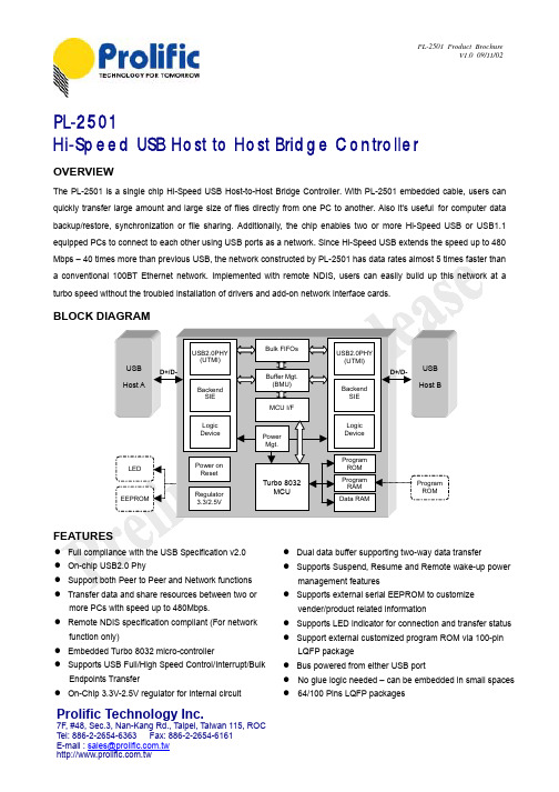
PL-2501中文资料
Prolific Technology Inc.
7F, #48, Sec.3, Nan-Kang Rd., Taipei, Taiwan 115, ROC Tel: 886-2-2654-6363 Fax: 886-2-2654-6161 E-mail : sales@
Power Mgt.
LED
Power on Reset Regulator 3.3/2.5V
Program ROM
Turbo 8032 MCU
Program RAM Data RAM
Program ROM
EEPROM
FEATURES
Full compliance with the USB Specification v2.0 On-chip USB2.0 Phy Support both Peer to Peer and Network functions Transfer data and share resources between two or more PCs with speed up to 480Mbps. Remote NDIS specification compliant (For network function only) Embedded Turbo 8032 micro-controller Supports USB Full/High Speed Control/Interrupt/Bulk Endpoints Transfer On-Chip 3.3V-2.5V regulator for internal circuit Dual data buffer supporting two-way data transfer Supports Suspend, Resume and Remote wake-up power management features Supports external serial EEPROM to customize vender/product related information Supports LED indicator for connection and transfer status Support external customized program ROM via 100-pin LQFP package Bus powered from either USB port No glue logic needed – can be embedded in small spaces 64/100 Pins LQFP packages
士徒特型号PG01_2 电路保护屏熔片,6.3x32mm,400-500VAC,400VDC,1-3
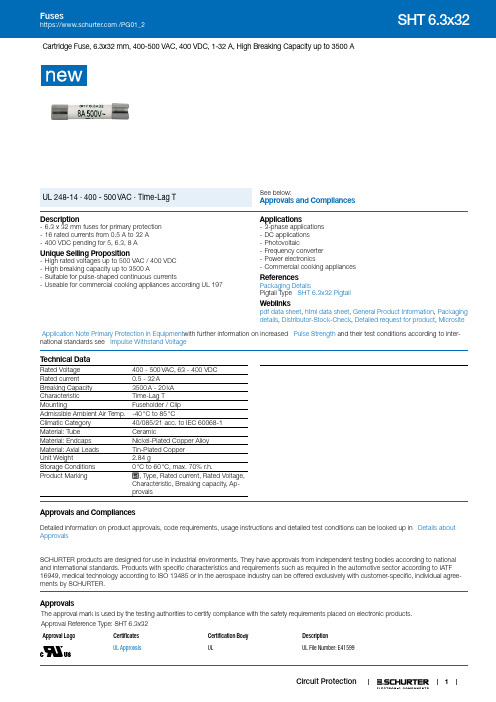
1Cartridge Fuse, 6.3x32 mm, 400-500 VAC, 400 VDC, 1-32 A, High Breaking Capacity up to 3500 ASee below:Approvals and Compliances UL 248-14 · 400 - 500 VAC · Time-Lag TDescription- 6.3 x 32 mm fuses for primary protection - 16 rated currents from 0.5 A to 32 A - 400 VDC pending for 5, 6.3, 8 AUnique Selling Proposition- High rated voltages up to 500 VAC / 400 VDC - High breaking capacity up to 3500 A- Suitable for pulse-shaped continuous currents- Useable for commercial cooking appliances according UL 197Applications- 3-phase applications - DC applications - Photovoltaic- Frequency converter - Power electronics- Commercial cooking appliancesReferences Packaging DetailsPigtail Type SHT 6.3x32 PigtailWeblinkspdf data sheet , html data sheet , General Product Information , Packaging details , Distributor-Stock-Check , Detailed request for product , MicrositeApplication Note Primary Protection in Equipment with further information on increased Pulse Strength and their test conditions according to inter-national standards see Impulse Withstand VoltageT echnical DataRated Voltage 400 - 500 VAC, 63 - 400 VDC Rated current 0.5 - 32 ABreaking Capacity 3500 A - 20 kA Characteristic Time-Lag TMountingFuseholder / Clip Admissible Ambient Air Temp.-40 °C to 85 °CClimatic Category 40/085/21 acc. to IEC 60068-1Material: Tube CeramicMaterial: Endcaps Nickel-Plated Copper Alloy Material: Axial Leads Tin-Plated Copper Unit Weight2.84 gStorage Conditions 0 °C to 60 °C, max. 70% r.h.Product Marking, Type, Rated current, Rated Voltage, Characteristic, Breaking capacity, Ap-provalsApprovals and CompliancesDetailed information on product approvals, code requirements, usage instructions and detailed test conditions can be looked up in Details about ApprovalsSCHURTER products are designed for use in industrial environments. They have approvals from independent testing bodies according to national and international standards. Products with specific characteristics and requirements such as required in the automotive sector according to IATF 16949, medical technology according to ISO 13485 or in the aerospace industry can be offered exclusively with customer-specific, individual agree-ments by SCHURTER.ApprovalsThe approval mark is used by the testing authorities to certify compliance with the safety requirements placed on electronic products. Approval Reference T ype: SHT 6.3x32Approval LogoCertificates Certification Body DescriptionUL ApprovalsULUL File Number: E41599Product standardsProduct standards that are referencedOrganization Design Standard DescriptionDesigned according to UL 248-14Low voltage fuses - Part 14: Additional fusesDesigned according to CSA22.2 No. 248.14Low-Voltage Fuses - Part 14: Supplemental Fuses Application standardsApplication standards where the product can be usedOrganization Design StandardDescriptionDesigned for applications acc.IEC/UL 60950IEC 60950-1 includes the basic requirements for the safety of informationtechnology equipment.CompliancesThe product complies with following Guide LinesIdentification Details Initiator DescriptionCE declaration of conformity SCHURTER AG The CE marking declares that the product complies with the applicablerequirements laid down in the harmonisation of Community legislation onits affixing in accordance with EU Regulation 765/2008.RoHS SCHURTER AG EU Directive RoHS 2011/65/EUChina RoHS SCHURTER AG The law SJ / T 11363-2006 (China RoHS) has been in force since 1 March2007. It is similar to the EU directive RoHS.REACH SCHURTER AG On 1 June 2007, Regulation (EC) No 1907/2006 on the Registration,Evaluation, Authorization and Restriction of Chemicals 1 (abbreviated as"REACH") entered into force.Dimension [mm] 6.3 mm23Time-Current-CurvesT i m e i n S e c o n d sMultiple of Rated Current InAll VariantsPackaging Unit xxxx.xxxx Small Box Pack (10 pcs.)xxxx.xxxx.G Bulk (1000 pcs.)The specifications, descriptions and illustrations indicated in this document are based on current information. All content is subject to modifications and amendments. Information furnished is believed 0 5 . 0 2 . 2 0 1 94。
PS2501-1-A中文资料
12
PS2501-2, PS2501L-2
8765 1234
1, 3. Anode 2, 4. Cathode 5, 7. Emitter 6, 8. Collector
PS2501-4, PS2501L-4
0.50±0.10
2.54
0.25 M
0
to 15˚ 0.25
+0.1 –0.05
2
Data Sheet PN10225EJ02V0DS
元器件交易网
Lead Bending Type (New package) PS2501L-1
4.6±0.35
PS2501-1,-2,-4, PS2501L-1,-2,-4
• UL approved: File No. E72422
APPLICATIONS
• Power supply • Telephone/FAX. • FA/OA equipment • Programmable logic controller
PIN CONNECTION (Top View)
PS2501-1, PS2501L-1
PS2501L-4
19.8±0.5
6.5±0.5
6.5±0.5
+0.1 –0.05
+0.1 –0.05
+0.1 –0.05
+0.1 –0.05
0.1
0.25
3.5±0.3
0.1
0.25
3.5±0.3
1.25±0.15 0.25 M 2.54
0.9±0.25 9.60±0.4 0.15
SN74VMEH22501AGQLR资料
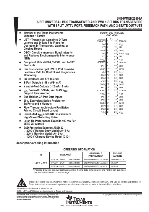
description/ordering information
ORDERING INFORMATION
TA PACKAGE† TSSOP − DGG −40°C to 85°C TVSOP − DGV VFBGA − GQL Tape and reel Tape and reel Tape and reel ORDERABLE PART NUMBER SN74VMEH22501ADGGR SN74VMEH22501ADGVR SN74VMEH22501AGQLR TOP-SIDE MARKING VMEH22501A VK501A VK501A
48 47 46 45 44 43 42 41 40 39 38 37 36 35 34 33 32 31 30 29 28 27 26 25
1OEAB VCC 1B GND BIAS VCC 2B VCC 2OEAB 3B1 GND VCC 3B2 3B3 VCC GND 3B4 CLKAB VCC 3B5 3B6 GND 3B7 3B8 VCC
SCES620 – DECEMBER 2004
D Member of the Texas Instruments D
D D D D D D D D D D UBT Transceiver Combines D-Type Latches and D-Type Flip-Flops for Operation in Transparent, Latched, or Clocked Modes OEC Circuitry Improves Signal Integrity and Reduces Electromagnetic Interference (EMI) Compliant With VME64, 2eVME, and 2eSST Protocols Bus Transceiver Split LVTTL Port Provides Feedback Path for Control and Diagnostics Monitoring I/O Interfaces Are 5-V Tolerant B-Port Outputs (−48 mA/64 mA) Y and A-Port Outputs (−12 mA/12 mA) Ioff, Power-Up 3-State, and BIAS VCC Support Live Insertion Bus Hold on 3A-Port Data Inputs 26-W Equivalent Series Resistor on 3A Ports and Y Outputs Flow-Through Architecture Facilitates Printed Circuit Board Layout Distributed VCC and GND Pins Minimize High-Speed Switching Noise Latch-Up Performance Exceeds 100 mA Per JESD 78, Class II ESD Protection Exceeds JESD 22 − 2000-V Human-Body Model (A114-A) − 200-V Machine Model (A115-A) − 1000-V Charged-Device Model (C101)
DVP ES 说明书
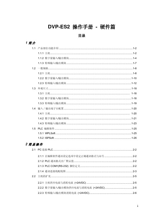
2.3.1 外部输入/输出接点的编号及功能 [X] / [Y] ......................................................... 2-7 2.3.2 主机数字量输入/输出点数配置 .......................................................................... 2-7 2.3.3 数字量输入/输出模块点数配置 .......................................................................... 2-7 2.3.4 数字量输入/输出点数配置范例 .......................................................................... 2-8 2.4 特殊输入/输出模块配置 ............................................................................................... 2-8 2.4.1 配置说明 ............................................................................................................ 2-8 2.4.2 混合配置范例..................................................................................................... 2-9 2.4.3 特殊寄存器 D9900 ~ D9999 使用说明............................................................... 2-9
DS2501中文资料
ORDERING INFORMATION:
PACKAGE TYPE
8 LEAD SO-8
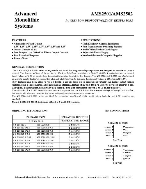
AMS2501CS AMS2501CS-1.5 AMS2501CS-1.8 AMS2501CS-2.5 AMS2501CS-2.85 AMS2501CS-3.0 AMS2501CS-3.3 AMS2501CS-3.5 AMS2501CS-5.0
元器件交易网
Advanced Monolithic Systems
AMS2501/AMS2502
1A VERY LOW DROPOUT VOLTAGE REGULATORS
FEATURES
• Adjustable or Fixed Output 1.5V, 1.8V, 2.5V, 2.85V, 3.0V, 3.3V, 3.5V and 5.0V
1.485 1.500
1.515
V
AMS2501/AMS2502-1.8
VCONTROL = 4V, VPOWER =2.V, ILOAD = 0mA
1.782 1.800
1.818
V
VCONTROL = 3V, VPOWER =2.3V, ILOAD = 0mA to 1A
1.773 1.800
1.827
AMS2502CS AMS2502CS-1.5 AMS2502CS-1.8 AMS2502CS-2.5 AMS2502CS-2.85 AMS2502CS-3.0 AMS2502CS-3.3 AMS2502CS-3.5 AMS2502CS-5.0
OPERATING JUNCTION
TEMPERATURE RANGE
V
AMS2501/AMS2502-2.5
VCONTROL = 5V, VPOWER =3.3V, ILOAD = 0mA
英飞凌 FF225R65T3E3 XHP 3 模块 数据表
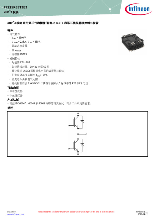
XHP ™3 模块 采用第三代沟槽栅/场终止IGBT3和第三代发射极控制二极管特性•电气特性-V CES = 6500 V-I C nom = 225 A / I CRM = 450 A -高动态稳定性-低 V CEsat -沟槽栅IGBT3•机械特性-封装的 CTI > 600-加强绝缘封装,10.4kV 交流 60 秒-碳化硅铝 (AlSiC) 基板提供更高的温度循环能力-扩大存储温度范围至 T stg = -55°C -高爬电距离和电气间隙-外壳材料符合EN45545-2 “铁路车辆防火”标准中的 R23 (HL3) 等级可选应用•牵引变流器•中压变流器产品认证•根据 IEC 60747、60749 和 60068标准的相关测试,符合工业应用的要求。
描述FF225R65T3E3XHP ™3 模块内容描述 . . . . . . . . . . . . . . . . . . . . . . . . . . . . . . . . . . . . . . . . . . . . . . . . . . . . . . . . . . . . . . . . . . . . . . . . . . . . . . . . . . . . . . . . .1特性 . . . . . . . . . . . . . . . . . . . . . . . . . . . . . . . . . . . . . . . . . . . . . . . . . . . . . . . . . . . . . . . . . . . . . . . . . . . . . . . . . . . . . . . . .1可选应用 . . . . . . . . . . . . . . . . . . . . . . . . . . . . . . . . . . . . . . . . . . . . . . . . . . . . . . . . . . . . . . . . . . . . . . . . . . . . . . . . . . . .1产品认证 . . . . . . . . . . . . . . . . . . . . . . . . . . . . . . . . . . . . . . . . . . . . . . . . . . . . . . . . . . . . . . . . . . . . . . . . . . . . . . . . . . . .1内容 . . . . . . . . . . . . . . . . . . . . . . . . . . . . . . . . . . . . . . . . . . . . . . . . . . . . . . . . . . . . . . . . . . . . . . . . . . . . . . . . . . . . . . . . .2 1封装 . . . . . . . . . . . . . . . . . . . . . . . . . . . . . . . . . . . . . . . . . . . . . . . . . . . . . . . . . . . . . . . . . . . . . . . . . . . . . . . . . . . . . . . . .3 2IGBT, 逆变器 . . . . . . . . . . . . . . . . . . . . . . . . . . . . . . . . . . . . . . . . . . . . . . . . . . . . . . . . . . . . . . . . . . . . . . . . . . . . . . . . .3 3二极管,逆变器 . . . . . . . . . . . . . . . . . . . . . . . . . . . . . . . . . . . . . . . . . . . . . . . . . . . . . . . . . . . . . . . . . . . . . . . . . . . . . . .5 4特征参数图表 . . . . . . . . . . . . . . . . . . . . . . . . . . . . . . . . . . . . . . . . . . . . . . . . . . . . . . . . . . . . . . . . . . . . . . . . . . . . . . . .6 5电路拓扑图 . . . . . . . . . . . . . . . . . . . . . . . . . . . . . . . . . . . . . . . . . . . . . . . . . . . . . . . . . . . . . . . . . . . . . . . . . . . . . . . . .10 6封装尺寸 . . . . . . . . . . . . . . . . . . . . . . . . . . . . . . . . . . . . . . . . . . . . . . . . . . . . . . . . . . . . . . . . . . . . . . . . . . . . . . . . . . .11 7模块标签代码 . . . . . . . . . . . . . . . . . . . . . . . . . . . . . . . . . . . . . . . . . . . . . . . . . . . . . . . . . . . . . . . . . . . . . . . . . . . . . . .12修订历史 . . . . . . . . . . . . . . . . . . . . . . . . . . . . . . . . . . . . . . . . . . . . . . . . . . . . . . . . . . . . . . . . . . . . . . . . . . . . . . . . . . .13免责声明 . . . . . . . . . . . . . . . . . . . . . . . . . . . . . . . . . . . . . . . . . . . . . . . . . . . . . . . . . . . . . . . . . . . . . . . . . . . . . . . . . . .141封装表 1绝缘参数特征参数代号标注或测试条件数值单位绝缘测试电压V ISOL RMS, f = 50 Hz, t = 60 s10.4kV 局部放电熄弧电压V isol RMS, f = 50 Hz, Q PD typ. 10 pC 5.1kV DC 稳定性V CE(D)T vj=25°C, 100 Fit3800V 模块基板材料AlSiC爬电距离d Creep端子至散热器53.0mm 爬电距离d Creep端子至端子53.0mm 电气间隙d Clear端子至散热器36.0mm 电气间隙d Clear端子至端子26.0mm 相对电痕指数CTI > 600表 2特征值特征参数代号标注或测试条件数值单位最小值典型值最大值杂散电感,模块L sCE25nH 模块引线电阻,端子-芯片R AA'+CC'T C=25°C, 每个开关0.33mΩ模块引线电阻,端子-芯片R CC'+EE'T C=25°C, 每个开关0.42mΩ储存温度T stg-55125°C 模块安装的安装扭距M根据相应的应用手册进行安装M6, 螺丝 4.25 5.75Nm端子安装扭矩M根据相应的应用手册进行安装M3, 螺丝0.9 1.1Nm M8, 螺丝810重量G700g 2IGBT, 逆变器表 3最大标定值特征参数代号标注或测试条件数值单位集电极-发射极电压V CES T vj = -50 °C5900VT vj = 125 °C6500连续集电极直流电流I CDC T vj max = 125 °C T C = 80 °C225A 集电极重复峰值电流I CRM t p受限于 T vj op450A 栅极-发射极峰值电压V GES±20V表 4特征值特征参数代号标注或测试条件数值单位最小值典型值最大值集电极-发射极饱和电压V CE sat I C = 225 A, V GE = 15 V T vj = 25 °C 3.00 3.40VT vj = 125 °C 3.70 4.20栅极阈值电压V GEth I C = 33 mA, V CE = V GE, T vj = 25 °C 5.406 6.60V 栅极电荷Q G V GE = ±15 V, V CE = 3600 V10.5µC 内部栅极电阻R Gint T vj = 25 °C0.67Ω输入电容C ies f = 100 kHz, T vj = 25 °C, V CE = 25 V, V GE = 0 V65.6nF 反向传输电容C res f = 100 kHz, T vj = 25 °C, V CE = 25 V, V GE = 0 V1nF 集电极-发射极截止电流I CES V CE = 6500 V, V GE = 0 V T vj = 25 °C5mA 栅极-发射极漏电流I GES V CE = 0 V, V GE = 20 V, T vj = 25 °C400nA开通延迟时间(感性负载)t don I C = 225 A, V CE = 3600 V,V GE = ±15 V, R Gon = 4.7 ΩT vj = 25 °C0.240µs T vj = 125 °C0.240上升时间(感性负载)t r I C = 225 A, V CE = 3600 V,V GE = ±15 V, R Gon = 4.7 ΩT vj = 25 °C0.070µs T vj = 125 °C0.080关断延迟时间(感性负载)t doff I C = 225 A, V CE = 3600 V,V GE = ±15 V, R Goff = 22 ΩT vj = 25 °C 6.000µs T vj = 125 °C 6.400下降时间(感性负载)t f I C = 225 A, V CE = 3600 V,V GE = ±15 V, R Goff = 22 ΩT vj = 25 °C0.950µs T vj = 125 °C 2.000开通损耗能量 (每脉冲)E on I C = 225 A, V CE = 3600 V,Lσ = 85 nH, V GE = ±15 V,R Gon = 4.7 Ω, di/dt =2200 A/µs (T vj = 125 °C)T vj = 25 °C1230mJ T vj = 125 °C1710关断损耗能量 (每脉冲)E off I C = 225 A, V CE = 3600 V,Lσ = 85 nH, V GE = ±15 V,R Goff = 22 Ω, dv/dt =2100 V/µs (T vj = 125 °C)T vj = 25 °C875mJ T vj = 125 °C1170短路数据I SC V GE≤ 15 V, V CC = 4500 V,V CEmax=V CES-L sCE*di/dt t P≤ 10 µs,T vj=125 °C1300A结-外壳热阻R thJC每个 IGBT29.1K/kW 外壳-散热器热阻R thCH每个 IGBT21.3K/kW 允许开关的温度范围T vj op-50125°C3二极管,逆变器表 5最大标定值特征参数代号标注或测试条件数值单位反向重复峰值电压V RRM T vj = -50 °C5900VT vj = 125 °C6500连续正向直流电流I F225A 正向重复峰值电流I FRM t P = 1 ms450A I2t-值I2t t P = 10 ms, V R = 0 V T vj = 125 °C45.2kA²s 最大损耗功率P RQM T vj = 125 °C1000kW 最小开通时间t onmin10µs表 6特征值特征参数代号标注或测试条件数值单位最小值典型值最大值正向电压V F I F = 225 A, V GE = 0 V T vj = 25 °C 3.10 3.55VT vj = 125 °C 2.85 3.25反向恢复峰值电流I RM V R = 3600 V, I F = 225 A,V GE = -15 V, -di F/dt =2200 A/µs (T vj = 125 °C)T vj = 25 °C405A T vj = 125 °C365恢复电荷Q r V R = 3600 V, I F = 225 A,V GE = -15 V, -di F/dt =2200 A/µs (T vj = 125 °C)T vj = 25 °C255µC T vj = 125 °C505反向恢复损耗(每脉冲)E rec V R = 3600 V, I F = 225 A,V GE = -15 V, -di F/dt =2200 A/µs (T vj = 125 °C)T vj = 25 °C450mJ T vj = 125 °C1070结-外壳热阻R thJC每个二极管51.3K/kW 外壳-散热器热阻R thCH每个二极管24.2K/kW 允许开关的温度范围T vj op-50125°C5电路拓扑图Beispiel: PrimePACK-3+ CostdownCommon Collektorxx.03.2019 mit WW, Jürgen Esch36NTC 9,11,13T23,4D29651T1D187202.08.2021 Beispiel für A.Schulz10: NC图 1FF225R65T3E3XHP ™3 模块5 电路拓扑图6 封装尺寸6封装尺寸图 27 模块标签代码7模块标签代码图 3修订历史修订历史修订版本发布日期变更说明V1.02017-12-19Target datasheetV1.12018-04-17Target datasheetV2.02018-04-23Preliminary datasheetn/a2020-09-01Datasheet migrated to a new system with a new layout and new revisionnumber schema: target or preliminary datasheet = 0.xy; final datasheet =1.xy1.102020-12-111.112022-04-12Final datasheet商标所有参照产品或服务名称和商标均为其各自所有者的财产。
- 1、下载文档前请自行甄别文档内容的完整性,平台不提供额外的编辑、内容补充、找答案等附加服务。
- 2、"仅部分预览"的文档,不可在线预览部分如存在完整性等问题,可反馈申请退款(可完整预览的文档不适用该条件!)。
- 3、如文档侵犯您的权益,请联系客服反馈,我们会尽快为您处理(人工客服工作时间:9:00-18:30)。
0.50±0.10
2.54
0.25 M
0
to 15˚ 0.25
+0.1 –0.05
2
Data Sheet PN10225EJ02V0DS
元器件交易网
Lead Bending Type (New package) PS2501L-1
4.6±0.35
PS2501-1,-2,-4, PS2501L-1,-2,-4
6
V
80
mA
1.5
1.2
mW/°C
150
120
mW/ch
1
A
80
V
7
V
50
mA/ch
1.5
1.2
mW/°C
150
120
mW/ch
5 000
Vr.m.s.
−55 to +100
°C
−55 to +150
°C
*1 PW = 100 µs, Duty Cycle = 1% *2 AC voltage for 1 minute at TA = 25°C, RH = 60% between input and output.
元器件交易网
PHOTOCOUPLER
PS2501-1,-2,-4, PS2501L-1,-2,-4
HIGH ISOLATION VOLTAGE SINGLE TRANSISTOR TYPE MULTI PHOTOCOUPLER SERIES
−NEPOC Series−
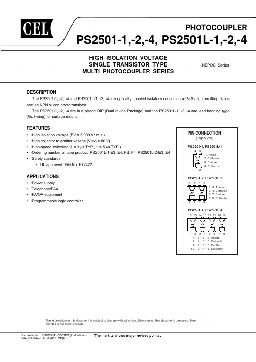
DESCRIPTION
Solder Plating Specification
Packing Style
Safety Standard Approval
Application Part Number *1
Solder
Magazine case 100 pcs
Standard products PS2501-1
contains lead
Caution New package 1-ch, 4-ch only
Lead Bending Type
PS2501L-1
4.6±0.5
0.9±0.25
2.54
0.15
9.60±0.4
PS2501L-2
9.7±0.5
6.5±0.5
6.5±0.5
+0.1 –0.05
+0.1 –0.05
+0.1 –0.05
The PS2501-1, -2, -4 and PS2501L-1, -2, -4 are optically coupled isolators containing a GaAs light emitting diode and an NPN silicon phototransistor.
The PS2501-1, -2, -4 are in a plastic DIP (Dual In-line Package) and the PS2501L-1, -2, -4 are lead bending type (Gull-wing) for surface mount.
16 15 14 13 12 11 10 9
1 234 56 7 8
1, 3, 5, 7. Anode 2, 4, 6, 8. Cathode 9, 11, 13, 15. Emitter 10, 12, 14, 16. Collector
Document No. PN10225EJ02V0DS (2nd edition) Date Published April 2005 CP(K)
PS2501-1 PS2501L-1 PS2501L-1-E3 PS2501L-1-E4 PS2501L-1-F3 PS2501L-1-F4 PS2501-2 PS2501L-2 PS2501L-2-E3 PS2501L-2-E4 PS2501-4 PS2501L-4 PS2501-1 PS2501L-1 PS2501L-1-E3 PS2501L-1-E4 PS2501L-1-F3 PS2501L-1-F4 PS2501-2 PS2501L-2 PS2501L-2-E3 PS2501L-2-E4 PS2501-4 PS2501L-4
FEATURES
• High isolation voltage (BV = 5 000 Vr.m.s.) • High collector to emitter voltage (VCEO = 80 V) • High-speed switching (tr = 3 µs TYP., tf = 5 µs TYP.) • Ordering number of tape product: PS2501L-1-E3, E4, F3, F4, PS2501L-2-E3, E4 • Safety standards
Power Dissipation
PD
Peak Forward Current*1
IFP
Transistor Collector to Emitter Voltage VCEO
Emitter to Collector Voltage VECO
Collector Current
IC
Power Dissipation Derating ∆PC/°C
PS2501L-4
19.8±0.5
6.5±0.5
6.5±0.5
+0.1 –0.05
+0.1 –0.05
+0.1 –0.05
+0.1 –0.05
0.1
0.25
3.5±0.3
0.1
0.25
3.5±0.3
1.25±0.15 0.25 M 2.54
0.9±0.25 9.60±0.4 0.15
1.25±0.15 0.25 M
The mark shows major revised points.
6.5±0.5
元器件交易网
PACKAGE DIMENSIONS (UNIT : mm) DIP Type (New package)
PS2501-1
4.6±0.35
7.62
6.5±0.5
PS2501-1,-2,-4, PS2501L-1,-2,-4
• UL approved: File No. E72422
APPLICATIONS
• Power supply • Telephone/FAX. • FA/OA equipment • Programmable logic controller
PIN CONNECTION (Top View)
PS2501-1, PS2501L-1
43 1. Anode 2. Cathode 3. Emitter 4. Collector
12
PS2501-2, PS2501L-2
8765 1234
1, 3. Anode 2, 4. Cathode 5, 7. Emitter 6, 8. Collector
PS2501-4, PS2501L-4
2.54
0
to 15˚ 0.25
+0.1 –0.05
0.50±0.10
0.25 M
1.25±0.15 2.54
PS2501-4
19.8±0.5
0.50±0.10 0.25 M
0
to 15˚ 0.25
+0.1 –0.05
6.5±0.5
7.62
3.3±0.5 4.15±0.4 3.5±0.3
1.25±0.15
(UL Approved)
Embossed Tape 1 000 pcs/reel
Embossed Tape 2 000 pcs/reel
Magazine case 45 pcs
PS2501-2
Embossed Tape 1 000 pcs/reel
Magazine case 20 pcs
PS2501-4
Standard PKG
D
F
New PKG
E*1
*1 PS2501-4 only
4
Data Sheet PN10225EJ02V0DS
元器件交易网
PS2501-1,-2,-4, PS2501L-1,-2,-4
ORDERING INFORMATION
Part Number
Assembly Lot
PS2501-1,-2,-4, PS2501L-1,-2,-4
No. 1 pin Mark
PS2501-2, -4
PS2501-2 MD003
Country Assembled Type Number Assembly Lot
M D 0 03
Week Assembled Year Assembled (Last 1 Digit) In-house Code CTR Rank Code
Order Number
PS2501-1 PS2501L-1 PS2501L-1-E3 PS2501L-1-E4 PS2501L-1-F3 PS2501L-1-F4 PS2501-2 PS2501L-2 PS2501L-2-E3 PS2501L-2-E4 PS2501-4 PS2501L-4 PS2501-1-A PS2501L-1-A PS2501L-1-E3-A PS2501L-1-E4-A PS2501L-1-F3-A PS2501L-1-F4-A PS2501-2-A PS2501L-2-A PS2501L-2-E3-A PS2501L-2-E4-A PS2501-4-A PS2501L-4-A
ABSOLUTE MAXIMUM RATINGS (Unless otherwise specified, TA = 25°C)