SD-350B-24中文资料
DDR-240系列产品说明书

■ Applications
Bus,tram,metro or railway system Industrial control system Semi-conductor fabrication equipment Factory automation Electro-mechanical Wireless network Telecom or datacom system
EN50155:2017-Comply with S1 level
OVERLOAD
Normally works within 150% rated output power for more than 3 seconds and then constant current protection 105~135% Note.5 rated output power with auto-recovery
MTBF
484.9K hrs min. Telcordia SR-332 (Bellcore) ; 189.9K hrs min. IL-HDBK-217F (25℃)
OTHERS DIMENSION
40*125.2*113.5mm (W*H*D)
OPERATING ALTITUDE Note.7 2000 meters
SAFETY STANDARDS
IEC 62368-1 (LVD, except for 67.2~154Vin), EAC TP TC 004, AS/NZS 62368.1 approved; Design refer to UL508
WITHSTAND VOLTAGE
I/P-O/P:4KVdc I/P-FG:2.5KVdc O/P-FG:0.71KVdc
BE24D 系列液晶显示器 用户指南说明书

BE24D系列液晶显示器用户指南第一版2018 年 7 月版权所有 © 2018 ASUSTeK COMPUTER INC. 保留所有权利。
未经 ASUSTeK COMPUTER INC.(“ASUS”) 明确书面同意,不得以任何形式或通过任何方式复制、传播、转录本手册的任何部分,包括其中介绍的产品和软件,也不得存储到检索系统中或翻译成任何语言,购买者出于备份目的而保留的文档除外。
在下列情况下,不能享受产品保修或维修服务: (1) 产品被修理、修改或改动,除非此类修理、修改或改动得到 ASUS 的书面授权;(2) 产品序列号损毁或缺失。
ASUS“按原样”提供本手册,不提供任何明示或隐含的担保,包括但不限于对于适销性或针对特定目的的适用性的隐含担保或条件。
无论在任何情况下,ASUS 及其董事成员、高级职员、员工或代理不对由于本手册或产品中存在任何缺陷或错误而导致的任何间接、特殊、偶然或必然损失(包括收益损失、业务损失、不能使用或数据丢失、业务中断等)承担任何责任,即使 ASUS 已被告知此类损失的可能性。
本手册中包含的规格和信息仅供一般性参考,可能会随时变更而无需另行通知,因此不应构成 ASUS 的承诺。
ASUS 对本手册(包括其中介绍的产品和软件)中可能存在的任何错误不承担任何责任。
本手册中出现的产品名称和公司名称可能分别是或不是相应公司的注册商标或版权,仅用于标示或解释目的,无意侵犯其所有者的权益。
ii目录 (iii)声明 (iv)安全信息 (vii)保养和清洁 (viii)中国产品回收服务 (ix)欧盟能源标签产品信息 (ix)第 1 章:产品介绍1.1 欢迎使用! ...................................................................................1-11.2 物品清单.........................................................................................1-11.3 显示器简介 .....................................................................................1-21.3.1 前部概览..........................................................................1-21.3.2 后部/侧面概览................................................................1-3第 2 章:设置2.1 安装显示器支撑臂/底座 ................................................................2-12.2 卸下支撑臂/底座(VESA 壁挂安装时) .......................................2-12.3 连接/卸下 MiniPC 套件.................................................................2-22.4 调整显示器 .....................................................................................2-32.5 调整摄像头 .....................................................................................2-42.6 连接线缆.........................................................................................2-52.7 打开显示器电源 ..............................................................................2-62.8 将显示器网络摄像头设为默认设置 .................................................2-62.9 将显示器网络扬声器设为默认设置 .................................................2-9第 3 章:一般说明3.1 OSD(屏幕显示)菜单...................................................................3-13.1.1 如何重新配置 ..................................................................3-1功能介绍.................................................................3-23.1.2 OSD3.2 规格摘要.........................................................................................3-83.3 外形尺寸.......................................................................................3-103.4 故障排除(常见问题) .................................................................3-113.5 支持的运行模式 ............................................................................3-12iiiiv联邦通信委员会声明本设备符合 FCC 规则第 15 部分的要求。
FR24中文资料
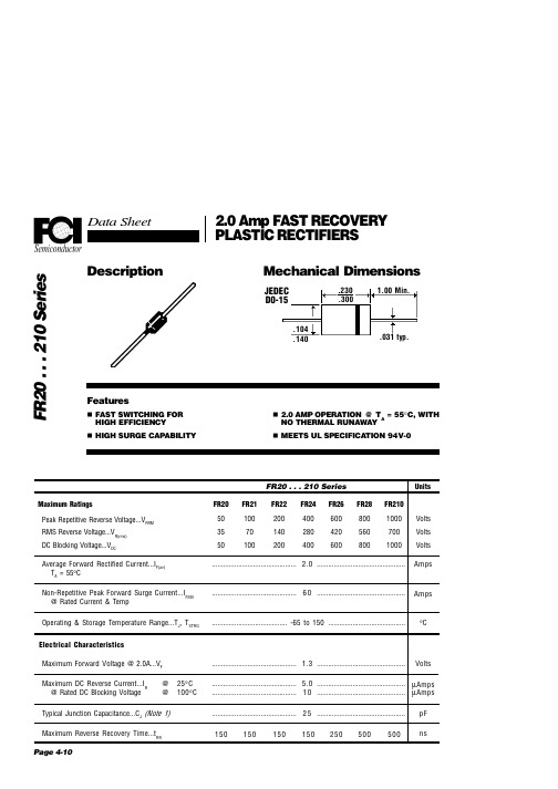
25 50 75 100 125 150 175 ° Ambient Temperature (°C)
100 10 Number of Cycles @ 60 Hz
Typical Instantaneous Forward Characteristics 100 Forward Current (A)
FR20 . . . 210 Series Maximum Ratings Peak Repetitive Reverse Voltage...VRRM RMS Reverse Voltage...VR(rms) DC Blocking Voltage...VDC Average Forward Rectified Current...IF(av) TA = 55°C Non-Repetitive Peak Forward Surge Current...IFSM @ Rated Current & Temp Operating & Storage Temperature Range...TJ, TSTRG Electrical Characteristics Maximum Forward Voltage @ 2.0A...VF Maximum DC Reverse Current...IR @ Rated DC Blocking Voltage @ @ 25°C 100°C ............................................. 1.3 ............................................... FR20 50 35 50 FR21 100 70 100 FR22 200 140 200 FR24 400 280 400 FR26 600 420 600 FR28 800 560 800 FR210 1000 700 1000
Cisco 350系列产品参数与价格表说明书
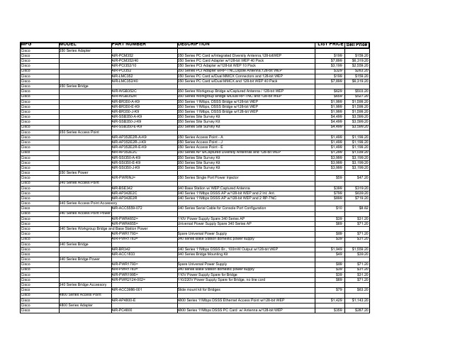
4800 Series Adapter
AIR-PC4800
DESCRIPTION
350 Series PC Card w/Integrated Diversity Antenna,128-bitWEP 350 Series PC Card Adapter w/128-bit WEP 40 Pack 350 Series PCI Adapter w/128-bit WEP 10 Pack 350 Series PCI Adapter w/RP-TNC,Dipole Antenna,128-bit WEP 350 Series PC Card w/Dual MMCX Connectors and 128-bit WEP 350 Series PC Card w/Dual MMCX and 128-bit WEP 40 Pack
350 Series Power
AIR-SSI350-J-K9 AIR-PWRINJ=
340 Series Access Point
AIR-BSE342
AIR-AP342E2C AIR-AP342E2R
340 Series Access Point Accessory AIR-ACC5559-072
350 Series Workgroup Bridge w/Captured Antenna / 128-bit WEP 350 Series Workgroup Bridge w/Dual RP-TNC and 128-bit WEP 350 Series 11Mbps, DSSS Bridge w/128-bit WEP 350 Series 11Mbps, DSSS Bridge w/128-bit WEP 350 Series 11Mbps, DSSS Bridge w/128-bit WEP 350 Series Site Survey Kit 350 Series Site Survey Kit 350 Series Site Survey Kit
三汇示波器说明书(Ver1.0)
DST4000 和 DST1000 系列数字存储示波器用户手册
i
目录
5.1 显示区 ........................................................................................ 20 5.2 信息区域..................................................................................... 23 5.3 波形显示..................................................................................... 23
三汇系列产品
DST4000 和 DST1000 系列 数字存储示波器
Version 1.0
杭州三汇科技有限公司 www.
目录
目录
目 录 ...........................................................................................................i 版权申明 .......................................................................................................................................................................v 第 1 章 安全事项......................................................................................... 1
SD-200B-24中文资料
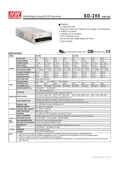
SPECIFICATIONSD-200B SD-200C MODELDC VOLTAGE RATED CURRENT CURRENT RANGE RATED POWEROUTPUTVOLTAGE ADJ. RANGE LINE REGULATION LOAD REGULATION SETUP, RISE TIME VOLTAGE RANGEEFFICIENCY (Typ.)INPUTINRUSH CURRENT (Typ.)OVER TEMPERATURE SAFETY STANDARDSEMS IMMUNITYWORKING TEMP.WORKING HUMIDITYSTORAGE TEMP., HUMIDITYTEMP. COEFFICIENT VIBRATION MTBFDIMENSION OTHERSNOTEPACKINGOVERLOADOVER VOLTAGEDC CURRENT (Typ.)5V 5V 12V 12V 24V 24V 48V 48V 34A 40A 16.7A 16.7A 8.4A 8.4A 4.2A 4.2A 0 ~ 34A 0 ~ 40A 0 ~ 16.7A 0 ~ 16.7A 0 ~ 8.4A 0 ~ 8.4A 0 ~ 4.2A 0 ~ 4.2A 170W 200W 200.4W 200.4W 201.6W 201.6W 201.6W 201.6W 100mVp-p100mVp-p 120mVp-p 120mVp-p 150mVp-p 150mVp-p 200mVp-p 200mVp-p 2.0% 2.0%1.0% 1.0%1.0% 1.0%1.0% 1.0%4.5 ~ 5.5VDC 4.5 ~ 5.5VDC 11 ~ 16VDC 11 ~ 16VDC 23 ~ 30VDC 23 ~ 30VDC 43 ~ 53VDC 43 ~ 53VDC 0.5%0.5%0.5%0.5%0.5%0.5%0.5%0.5%1.0%1.0%1.0%1.0%1.0%1.0%1.0%1.0%300ms, 50ms at full loadB:19 ~ 36VDC C:36 ~ 72VDC D:72 ~144VDC 79%81%10.8A/24V 5.4A/48V82%84%85%86%86%86%10.6A/24V 5.2A/48V10.4A/24V 6.7A/48V10.4A/24V5A/48VC:45A/48VDC D:45A/96VDC105 ~ 135%rated output power5.75 ~6.75V 5.75 ~ 6.75V16.8 ~ 20V 16.8 ~ 20V31.5 ~ 37.5V 31.5 ~ 37.5V53 ~ 65V 53 ~ 65VProtection type :Shut down o/p voltage, re-power on to recover Protection type : Shut down o/p voltage, re-power on to recover Protection type : Shut down o/p voltage, recovers automatically after temperature goes down Compliance to EN55022 (CISPR22) Class BCompliance to ight EN61000-4-2,3,4,6,8; ENV50204, l industry level, criteria A -20 ~ +60(Refer to output load derating curve)20 ~ 90% RH non-condensing -40 ~ +85, 10 ~ 95% RH0.03%/(0 ~ 5010 ~ 500Hz, 2G 10min./1cycle, 60min. each along X,Y, Z axes218.2K hrs min. MIL-HDBK-217F (25)215*115*50mm (L*W*H)1.1Kg; 12pcs/14.4Kg/0.92CUFT1. All parameters NOT specially mentioned are measured at 24,48,96VDC input, rated load and 25of ambient temperature.2. Ripple & noise are measured at 20MHz of bandwidth by using a 12" twisted pair-wire terminated with a 0.1uf & 47uf parallel capacitor.3. Tolerance : includes set up tolerance,line regulation and load regulation.4. The power supply is considered a component which will be installed into a final equipment. The final equipment must be re-confirmed that it still meets EMC directives.2:1 wide input rangeProtections: Short circuit / Overload / Over voltage / Over temperature 1500VDC I/O isolation Cooling by free air convection 100% full load burn-in test24V and 48V input voltage design refer to LVD 2 years warrantyFeatures :SAFETY &EMC(Note 4)WITHSTAND VOLTAGEISOLATION RESISTANCE I/P-O/P:1.5KVAC I/P-FG:1.5KVAC O/P-FG:0.5KVAC I/P-O/P, I/P-FG, O/P-FG:100M Ohms/500VDC EMI CONDUCTION & RADIATIONENVIRONMENT PROTECTION RIPPLE & NOISE (max.)Note.2VOLTAGE TOLERANCE Note.3955(1005for SD-200B-12 only)TSW1 detect on main power transistorUL60950-1approved (for SD-200C-24 type only), IEC60950-1 CB approved by TUV (for D type only)(for D type only)(for SD-200C-24 type only)SPECIFICATIONMODELDC VOLTAGE RATED CURRENT CURRENT RANGE RATED POWEROUTPUTVOLTAGE ADJ. RANGE LINE REGULATION LOAD REGULATION SETUP, RISE TIME VOLTAGE RANGEEFFICIENCY (Typ.)INPUTINRUSH CURRENT (Typ.)OVER TEMPERATURE SAFETY STANDARDSEMS IMMUNITY WORKING TEMP.WORKING HUMIDITYSTORAGE TEMP., HUMIDITYTEMP. COEFFICIENT VIBRATIONMTBFDIMENSION OTHERSNOTEPACKINGOVERLOADOVER VOLTAGEDC CURRENT (Typ.)Protection type :Shut down o/p voltage, re-power on to recover Protection type : Shut down o/p voltage, re-power on to recover 855(TSW1) detect on main power transistorProtection type : Shut down o/p voltage, recovers automatically after temperature goes down Compliance to EN55022 (CISPR22) Class BCompliance to ight EN61000-4-2,3,4,6,8; ENV50204, l industry level, criteria A -20 ~ +60(Refer to output load derating curve)20 ~ 90% RH non-condensing -40 ~ +85, 10 ~ 95% RH0.03%/(0 ~ 5010 ~ 500Hz, 2G 10min./1cycle, 60min. each along X,Y, Z axes 218.2K hrs min. MIL-HDBK-217F (25)215*115*50mm (L*W*H)1.1Kg; 12pcs/14.4Kg/0.92CUFTFeatures :WITHSTAND VOLTAGEISOLATION RESISTANCE I/P-O/P:1.5KVAC I/P-FG:1.5KVAC O/P-FG:0.5KVACI/P-O/P, I/P-FG, O/P-FG:100M Ohms/500VDCSAFETY &EMC(Note 4)EMI CONDUCTION & RADIATION ENVIRONMENT PROTECTION 1. All parameters NOT specially mentioned are measured at 24,48,96VDC input, rated load and 25of ambient temperature.2. Ripple & noise are measured at 20MHz of bandwidth by using a 12" twisted pair-wire terminated with a 0.1uf & 47uf parallel capacitor.3. Tolerance : includes set up tolerance,line regulation and load regulation.4. The power supply is considered a component which will be installed into a final equipment. The final equipment must be re-confirmed that it still meets EMC directives.105 ~ 135%rated output powerRIPPLE & NOISE (max.)Note.2VOLTAGE TOLERANCE Note.3SD-200D 5V 12V 24V 48V 40A 16.7A 8.4A 4.2A 0 ~ 40A 0 ~ 16.7A 0 ~ 8.4A 0 ~ 4.2A 200W 200.4W 201.6W 201.6W 100mVp-p120mVp-p 150mVp-p 200mVp-p 2.0% 1.0% 1.0% 1.0%4.5 ~ 5.5VDC 11 ~ 16VDC 23 ~ 30VDC 43 ~ 53VDC 0.5%0.5%0.5%0.5%1.0%1.0%1.0%1.0%300ms, 50ms at full loadB:19 ~ 36VDC C:36 ~ 72VDC D:72 ~144VDC 82%3.5A/96V 82%84%90%3.5A/96V3.5A/96V3.5A/96VC:45A/48VDC D:45A/96VDC5.75 ~6.75V 16.8 ~ 20V31.5 ~ 37.5V53 ~ 65V2:1 wide input rangeProtections: Short circuit / Overload / Over voltage / Over temperature 1500VDC I/O isolation Cooling by free air convection 100% full load burn-in test24V and 48V input voltage design refer to LVD 2 years warrantyIEC60950-1 CB approved by TUV (for D type only)(for D type only)Mechanical SpecificationDerating Curve Case No. 912B Unit:mmAMBIENT TEMPERATURE ()L O A D (%)10010020406080-202030405060SD-200B,C,D-5othersSD-200B-12SD-200B-24SD-200B-48Static CharacteristicsB:19C:36D:722448963672144L O A D (%)Ta=25901008070605040INPUT VOLTAGE (V)(HORIZONTAL)fosc : 100KHzBlock DiagramCIRCUITDETECTION FGO.V.P.O.L.P.CONTROLPWM FILTERINGFILTERI/PFILTERRECTIFIERSEMIFILTER&POWER SWITCH-RECTIFIERS&+V -VO.T.P.21532.513 max.4-M4 L=6mm5025150C LTerminal Pin No.Assignment :Pin No.Pin No.14,5,6327,8,9Assignment Assignment DC INPUT V+DC OUTPUT V-DC INPUT V-DC OUTPUT V+FG+V ADJ.LED 1032.5508511550.5117.515032.5177.527.58.39.55-M3 L=3mm4-M4 L=5mm 756341289。
SD-500L-24中文资料

SPECIFICATIONMODELDC VOLTAGE RATED CURRENT CURRENT RANGE RATED POWEROUTPUTVOLTAGE ADJ. RANGE LINE REGULATION LOAD REGULATION SETUP, RISE TIME VOLTAGE RANGENote.5EFFICIENCY (Typ.)INPUTFUNCTIONINRUSH CURRENT (Typ.)OVER TEMPERATURE WORKING TEMP.OUTPUT OK SIGNALREMOTE ON/OFF CONTROL WORKING HUMIDITYSTORAGE TEMP., HUMIDITY TEMP. COEFFICIENT VIBRATIONMTBF DIMENSION OTHERSNOTEPACKINGOVERLOAD OVER VOLTAGEDC CURRENT (Typ.)CURRENT (AT NO LOAD)500ms, 50ms at full load 19 ~ 72VDC24.2A/19VDC 24.8A/24VDC 12A/48VDC Max. 0.2A/48VDC 60A/48VDC105 ~ 125%rated output powerProtection type :Constant current limiting, shut down o/p voltage after about 5 sec., re-power on to recover 16 ~ 19V805(L-48V,H-24V,H-48V), 855(L-24V), 905(L-12V), 955(H-12V) (TSW2 : detect on heatsink of o/p diode)30.8 ~ 35.2V 62 ~ 68V 16 ~ 19V30.8 ~ 35.2V62 ~ 68VProtection type : Shut down o/p voltage, re-power on to recover 805(TSW1 )detect on heatsink of power transistorProtection type : Shut down o/p voltage, recovers automatically after temperature goes down-20 ~ +60(Refer to output load derating curve)Please refer to function manualOpen collector signal low when PSU turns on, max. sink current :10mA 20 ~ 90% RH non-condensing-40 ~ +85, 10 ~ 95% RH0.02%/(0 ~ 50)10 ~ 500Hz, 2G 10min./1cycle, 60min. each along X,Y, Z axes 196.3K hrs min. MIL-HDBK-217F (25)215*115*50mm (L*W*H)1.15Kg; 12pcs/14.8Kg/0.92CUFT86%88%89%87%8A/72VDC 6A/96VDC60A/96VDCMax. 0.1A/96VDC 89%90%0.5%0.5%0.5%0.5%72 ~ 144VDC0.5%0.5%0.5%0.5%0.5%0.5%0.5%0.5%1.0% 1.0% 1.0% 1.0% 1.0% 1.0%150mVp-p11 ~ 15V 150mVp-p 23 ~ 30V 150mVp-p 46 ~ 60V 150mVp-p 11 ~ 15V 150mVp-p 150mVp-p 23 ~ 30V 46 ~ 60V 12V 40A 0 ~ 40A 480W 24V 21A 0 ~ 21A 504W 48V 10.5A 0 ~ 10.5A 504W 12V 40A 0 ~ 40A 480W 24V 48V 21A 10.5A 0 ~ 21A 0 ~ 10.5A 504W 504W SD-500L-12SD-500L-24SD-500L-48SD-500H-12SD-500H-24SD-500H-481. All parameters NOT specially mentioned are measured at 48, 96VDC input, rated load and 25of ambient temperature.2. Ripple & noise are measured at 20MHz of bandwidth by using a 12" twisted pair-wire terminated with a 0.1uf & 47uf parallel capacitor.3. Tolerance : includes set up tolerance, line regulation and load regulation.4. The power supply is considered a component which will be installed into a final equipment. The final equipment must be re-confirmed that it still meets EMC directives.5. Derating may be needed under low input voltages. Please check the derating curve for more details.SAFETY STANDARDSEMS IMMUNITY IEC60950-1 CB approved by TUVCompliance to EN55022 (CISPR22)Class B Compliance to EN61000-4-2,3,4,6,8; ENV50204, light industry level, criteria A RIPPLE & NOISE (max.)Note.2VOLTAGE TOLERANCE Note.3EMI CONDUCTION & RADIATION WITHSTAND VOLTAGEISOLATION RESISTANCE I/P-O/P:2KVAC I/P-FG:1.5KVAC O/P-FG:0.5KVACI/P-O/P, I/P-FG, O/P-FG:100M Ohms/500VDC 2570%RHENVIRONMENT SAFETY &EMC(Note 4)PROTECTIONDC input active surge current limitingProtections: Short circuit / Overload / Over voltage / Over temperature/ Input polarity(by fuse)2000VAC I/O IsolationForced air cooling by built-in DC fan with fan speed control function Output OK SignalBuilt-in remote ON-OFF control Built-in remote sense function 3 years warrantyWide 4:1~2:1 DC input range (24V: 19~72VDC, 96V:72~144VDC)Features :Mechanical SpecificationDerating CurveStatic CharacteristicsCase No. 912AUnit:mmL O A D (%)INPUT VOLTAGE (VDC)19243648729614490for SD-500L for SD-500H100807570605040Block DiagramAMBIENT TEMPERATURE ()L O A D (%)20406080100-2001020304045506070Ta=25BOOST fosc : 65KHz PWM fosc : 110KHzFANO.V.P.-V +V RECTIFIERS&FILTER-S+SCIRCUIT DETECTION POWERAUX REMOTE CONTROLON/OFFOUTPUT LIMITINGACTIVE CURRENT INRUSH CONTROLING I/PSWITCH-POWER FILTEREMI PWM BOOSTBOOST CONTROL O.T.P.O.L.P.Control P (CN3) : JST B6B-PHDSS or equivalentin No.Assignment Pin No.Pin No.154236AssignmentAssignment +S -SOUTPUT OKRCGRC GND Mating Housing JST PHDR-06VS or equivalentTerminal JST SPHD-002T-P0.5or equivalentDC Input Terminal Pin No.AssignmentPin No.Pin No.14,5326,7Assignment AssignmentFGDC INPUT V-+VDC INPUT V+-V 1615C L4-M4 L=5mm 5-M3 L=3mm27.5177.532.5150117.510955032.550.511547.738.9532.51502156-M4 L=5mm2550Air flowdirection14 max.135LED+V ADJ.CN32 16 554671238.610only for SD-500L-12(HORIZONTAL)1.Remote ON/OFF(1)Remote ON/OFF control becomes available by applying voltage in CN3(2)Table 1.1 shows the specification of Remote ON/OFF function(3)Fig.1.2 shows the example to connect Remote ON/OFF control functionTable 1.1 Specification of Remote ON/OFF Fig.1.2 Examples of connecting remote ON/OFFConnection Method Output on SW Open Fig. 1.2(A)Output off SW Close 1KRCGRCSW5V1KRCVRCG(A)Using external voltage source(B)Using external voltage source2.Output OK signal"Output OK" is an open collector signal.It indicates the output status of the PSU. It can operate in two ways : One is sinking current from external signal ;the other is sending out a voltage signal.The maximum sink current is 10mA and the maximum external voltage is 13V.2-1 Sink current :2-2 Voltage signal :Between O/P OK(pin3) and GND(pin4)0 ~ 0.5V 12 ~ 13VOutput StatusON OFFV=0~0.8Vdc V=4~10VdcFig. 1.2(B)Function Description of CN3Function ManualPin No.Function Description135642+S O/P OK RC RCGGND -SOpen collector signal, reference to pin4(GND). Low when PSU turns on.The maximum sink current is 10mA and the maximumexternal voltage is 13V.Remote ON/OFFRemote ON/OFF groundThese pins connect to the negative terminal (-V).Negative sensing.The -S signal should be connected to the negative terminal of the load.The -S and +S leads should be twisted in pair to minimize noise pick-up effect.The maximum line drop compensation is 0.5V.Positive sensing.The +S signal should be connected to the positive terminal of the load.The +S and -S leads should be twisted in pair tominimize noise pick-up effect.The maximum line drop compensation is 0.5V.+S 1-S 2O/P OK RC GNDRCG CN356+V ADJ.+Vo +Vo -Vo -Vo TB1CN31 52 6The remote sensing compensates voltage drop on the load wiring up to 0.5V.3.Remote Sense+S 1-S 2O/P OK RC GNDRCG CN356+V ADJ.+Vo +Vo -Vo -Vo TB1CN31 52 6-+LOAD -S (pin2)Sense lines should be twisted in pairs+S (pin1)。
SD系列保护设备产品介绍说明书

The SD Series is a range of surge protection devices combining unparalleled packing densities, application versatility, proven reliable hybrid circuitry, simple installation and optional ‘loop disconnect’facilities – features which make the series the ultimate surge protection solution for process equipment, systems I/O and communications networks.The exceptionally high packing densities are the consequence of an ultra slim ‘footprint’ for individual modules which can thus ‘double-up’ as feedback terminals. Each module provides full hybrid surge protection for 2 and 3 wire loop protection.Modules with a comprehensive range of voltage ratings cover all process related signals such as RTDs, THCs, 4 to 20mA loops, telemetry outstations, shut-down systems and fire and gas detectors. Optional ‘loop disconnect’,is a feature which allows commissioning and maintenance to be carried out without removal of the surge protection device.This facility is provided by the SD07, SD16,SD32 and SD55 units. In addition, a thirdconnection on the field and safe side ofthe protector is provided in order toterminate screens safely.For three wire applications the speciallydesigned SD RTD(ResistanceTemperature Detector) and the SD32T3,(for separately powered 4-20mA loops)provide full 3-wire protection in a singlecompact unit. The recommended choicefor the protection of 3-wire pressuretransducers on low power circuits is theSD07R3.For higher bandwidth applications,theSDR series has been developed to meetthe demands of today’s highest speedcommunication systems.120V and 240V AC versionsare available for I/O andpower supplies up tothree Amps of loadcurrent.Telephone networks can be protected bythe SDPSTN.One simple manual operation clampsmodules securely onto DIN rail, whichautomatically provides the essential high-integrity earth connection.‘Top-hat’ (T-section) DIN rail is generallysuitable for mounting SD modulesalthough for adverse environments, aspecially-plated version is available fromMTL Surge Technologies. Acomprehensive range of mounting andearthing accessories can also besupplied, see page 7 for furtherdetails.Ultra-slim user-friendly devices for protecting electronic equipment and systems against surges on signal and I/O cablingSD SeriesO Range of ATEX Certified intrinsically safe surge protectorsO Ultra-slim space-saving design; easy installationO Multistage hybrid protection circuitry – 10kA maximum surge currentO Range of voltage ratings -- to suit all process I/O applicationsO High bandwidth, low resistance, RTD, PSTN and 3-wire transmitter versions availableGuide to applications and selectionAnalogue inputs(high-level)2-wire transmitters, 4-20mA, conventional and smartThe SPDs recommended for use with ‘conventional’and ‘smart’ 4-20mA transmitters(fed by a well-regulated supply) are the SD32 and SD55, the choice depending upon the maximum working voltage of the system (32V and 55V respectively). The diagram illustrates a prime example of an application for which the fuse/disconnect facility is particularly useful, however, both models are available in ‘X’versions without the optional fuse/disconnect feature.Analogue inputs(low-level)RTDsThese applications are best served using the SD RTD. F or optimum accuracy, the energising current should be chosen to ensure the voltage across the RTD does not exceed 1V over the full measurement range. When using a PT100 device, we recommend an energising current of 1mA.ac sensors, photocells, THCs, mV sources and turbine flowmetersThe SD07 or SD16 (depending upon the operational voltage) are the favoured choices for this application. SD07X and SD16X are also suitable.4561232xSD16X, SD32XPIVOVSD16 SD32 SD55SD16X SD32X SD55X (no fuse)456123SDVLogic signalOVSD07 SD16 SD32 SD55SD07X SD16X SD32X SD55X (no fuse)456123LED AlarmSD32X32V maxSD32SD32X(no fuse)IncomingtelephonelineModem,fax ortelephone456123Final output fromPLC,DCS,SCADAetc.110/120V acor220/240V acAnalogue outputsController outputs (I/P converters)F or this application, the recommendations are the SD16, SD32 and SD55 (and the equivalent ‘X’ versions), the final choice depending upon the operating voltage.Digital (on/off) inputsSwitchesSuitable SPDs for switches include the SD07, SD16, SD32 and SD55 modules – the choice depending upon the operating voltage of the system. The ‘X’ versions of these are also suitable. Digital (on/off) outputs Alarms, LEDs, solenoid valves, etcThe recommended choice for this application is the SD32 or SD32X.Telemetry (PSTN)Telemetry outstationsThe SD PSTN has been designed specifically for the protection of signals transmitted on public switched telephone networks.AC supplied equipmentPLC, I/O systemsFor systems on 110-120V ac, the SD150X is the recommended choice and for 220-240V ac systems, the SD275X is recommended.Controller outputs(I/P converters)SwitchesAlarms, LEDs,solenoid valves, etc.Telecom linePLC, I/O systemsFIELD CIRCUIT PROTECTED CIRCUIT32-wire transmitters or sensors4-20mA transmitters, conventional and smartWhere the TP48 is not an acceptable solution, either because of technical suitability or difficulties in mounting, the SD16X, SD32X and SD55X are an excellent alternative.3-wire transmitters or sensorsVibration Sensors and 4-20mA loop processcontrol systems invariably require threewire connections, when powered from anexternal source.This may be accomplished in one unit by usingthe SD32T3 three terminal Surge ProtectionDevice (SPD).Because the SD32T3 protects all threeconductors within the same unit, higherprotection is achieved, as the SPD hybridcircuitry is common to all three wires.The SD07R3 is available for the protection of 3-wire pressure transducers on low powercircuits.4-wire transmitters orsensorsFlow meters, level detectors, etc.4-wire systems such as level detectors requiretwo SDs, one for the supply and the other forthe transmitter output. Generally the voltagesacross the pairs are similar and so therecommended choice would be a pair ofSD16X, SD32X or SD55Xs. However, mainspowered transmitters should be protected withan SD150X or 275X (depending upon supplyvoltage) for the supply inputs.Loadcells are catered for by MTL SurgeTechnologies’ LC30 which is suitable for both 4and 6-wire load cells.series makes it the obvious choice for transmitter protection.The SDs within the junction box should be installed no further than one metre away but as close as possible to the sensor or transmitter they are protecting. A bond is required from the general mass of steelwork to the sensor or transmitter housing either using a flat short braid or a cable of at least 4mm2cross sectional area. In most instances this bond is automatically made by fixing the metallic transmitter housing to the plant structure. This bond ensures the voltage difference between the signal conductors and the transmitter housing is below the transmitter’s insulation rating. Please note that the transmitters or sensors are connected to the ‘Protected Equipment’ terminals of the SD and not the ‘Field Cables’.456123456123456123456123TP48SD32R (no fuse)SD32R (no fuse)SD32R (no fuse)TP48Communication systems protectionHigh speed data links between buildings or one part of a plant to another have become more common with the widespread use of smart transmitters and the increase in unmanned installations. The SD series has an SPD suitable for all process I/O applications with a choice of low resistance units, high bandwidth and a variety of voltage variants. The SDR series has been specially designed to meet the requirements for high speed data links with an extremely high bandwidth.Communication systemsRS232, RS422, RS485The recommended choice for these applications is the SD16R or SD32R depending on the maximum driver signal.Bus powered systemsThere are a variety of bus powered systems specially designed for the process industry. The ideal surge protection device for these systems is the SD32R as it has a very high bandwidth and a modest in-line resistance.Typical ApplicationsTable 1 shows suitable SD devices for different applications. In some applications alternative devices may be used, for example, where lower in-line resistance or a higher voltage power supply is used.Telematic have operationally tested therecommended SD series with representative highways listed but no formal approval for their use in systems by the respective bodies has been sought.RS232, RS422, RS485Bus powered systemsTable 1TP PROTECTED FIELD CIRCUITSD PROTECTED HOST CIRCUITPROTECTED FIELD CIRCUITSD PROTECTED HOST CIRCUITApplicationPreferred SPDAlternativeAllen Bradley Data Highway Plus SD16RFoundation Fieldbus 31.25kbits/s voltage mode SD32R 1.0/2.5 Mbits/s SD55R HART SD32X SD32, SD32R Honeywell DE SD32XSD32, SD32RLonWorks FFT-10SD32R LPT-10SD55R TP-78SD07R IS78†SD32R Modbus ‘& Modbus Plus (RS485)SD16R PROFIBUS DPSD32R PA (IEC 1158, 31.25 kbits/s)SD32R RS232SD16SD16XRS422SD07R RS423SD07R RS485SD07R WorldRP (IEC 1158)SD32R31.25 kbits/s voltage mode 1.0/2.5 Mbits/sSD55RThe SDs should be mounted on the field wiring side to ensure that any surges entering from the field do not damage any intrinsically safe barriers or galvanic isolators in the system. The SDs and IS interfaces should be mounted close to each other but on separate DIN rails in order to maintain the required 50mm clearance between safe area and hazardous area terminals.EarthingThe recommended earthing for field mounted devices has been illustrated previously but it is the earthing at the control panel that is more critical as there are usually a number of earthing systems, each with their own requirements. The earthing system illustrated here replaces the instrument 0V bond, the control system PSU bond and the IS earth with one single earth connection to meet all the design requirements and give the most effective protection against the effects of lightning induced surges.Zone 0 are considered real enough to require preventative measures. IEC 60079-14 (1996-12) Electrical apparatus for explosive gas atmospheres Part 14: Electrical installations in hazardous areas (other than mines) stresses the importance of SPDs in hazardous areas. An outdoor installation where there is a high likelihood of both lightning induced transients and combustible gases requires the installation of SPDs to prevent possible ignition of the gases. Areas seen particularly at risk include flammable liquid storage tanks, effluent treatment plants, distillation columns in petrochemical works and gas pipelines.SPDs for transmitter protection should be installed in Zone 1 but sufficiently close to the Zone 0 boundary to prevent high voltages entering Zone 0. The distance from the SPD to Zone 0 should be less than one metre where possible. However, in practice the SPD would normally be mounted on the transmitter or sensor housing which usually lies in Zone 1and is very close to Zone 0. Because there is only a very small free volume, the SD Series is suitable for mounting in flameproof or explosion proof enclosures.Zone 2The SD series is suitable for protecting electrical circuits in Division 2, Zone 2 and can be used without affecting the safety aspects of the circuit.Non-incendive (low-current) circuits can be protected using any SD series unit mounted in either the safe or hazardous area including those with the fuse disconnect facility. Non arcing (high current) circuits can also be protected except that SPDs with the fuse disconnect facility may only be mounted in the safe area. F or use in these circuits the units must be mounted in a suitable enclosure, normally the minimum requirements are IP54 and 7Nm resistance to impact. The SD series is self certified by Telematic Ltd as being suitable for this purpose.CertificationIntroducing surge protection into Intrinsically Safe (IS) circuits is trouble free as long as the current and power parameters are not exceeded. In the SD Series, the SD**X, SD**R,SD**R3, SD RTD and SD**T3 all have ATEX certification for use in IS circuits located in Zones 0, 1 or 2. The certification parameters for the SD**X and SD**T3 are:EEx ia IIC T4, Li = 0.22mH Ii = 260mA for Ui up to 20V Ii = 175mA for Ui up to 26V Ii = 140mA for Ui up to 28V Ii = 65mA for Ui up to 60VThe certification parameters for the SD**R,SD**R3 and SD RTD are:EEx ia IIC T4, Li = 0Ii = 260mA for Ui up to 60VThe power rating for each of the above is dependent on the table shown below.Pi = 1W (–30°C to +75°C)Pi = 1.2W (–30°C to +60°C) Pi = 1.3W (–30°C to +40°C) The SD** Series are classifed as simple apparatus and are intended for use in Zone 2 or safe areas only, because their fuses are not fully encapsulated.SD Series mounting kits and accessories The SD Series has a full range of mounting kits and accessories to simplify installation and tagging of individual loops. Insulating spacers (ISP7000) are available to allow mounting of the units onto backplanes without compromising correct earthing practice.These are placed at regular intervals along the rail or at each end as required. Earth connections can be made to the DIN rail via the earth terminal (ETL7000). Weatherproof enclosures are also available with all the necessary mounting accessories to install the SD series surge protection devices.Two tagging systems are available. One consists of tagging strips (TAG57) with labels (TGL57) mounted on posts (IMB57) at each end of a row of surge protection devices (SPDs). The other consists of separate tagging identifiers (BRI7000) mounted on the tops of individual SPDs. Both methods can be used conjointly. Replaceable fuses or solid links are available in packs of 5 (SD-F25, SD-F05 and SD-LNK). 7BRI700012BIL7000/BIL7000LSpecification(all figures typical at 25°C unless otherwise stated)Note: all figures are typical at +25°C unless otherwise stated; *standard fuse; +over full working temperature range; †at 20mA with a 250mA standard fuse; ‡these units need external 3A fuses; ^Signal; **Power & Common; maximum energising current depends upon RTD resistance.ProtectionFull hybrid line to lineEach line to screen/groundNominal discharge surge current (I n )10kA (8/20µs),(not applicable to SD150X and SD275X)Nominal discharge surge current (I n )6.5kA (8/20µs),(SD150X and SD275X only)Reaction time (T a )Within nanoseconds (10–9s)RTD resistance range (SD RTD )10 to 1500ΩDegradation accuracy (SD RTD at 1mA)0.1% (RTD resistance >100Ω)0.1Ω(RTD resistance < 100Ω)Ambient temperature–30°C to +75°C (working)–40°C to +80°C (storage)Humidity5 to 95% RH (non-condensing)Terminals2.5mm 2(12 AWG)MountingT-section DIN-rail(35 x 7.5 or 35 x 15mm rail)Weight70g approximately Case flammability UL94 V-2EMC complianceTo Generic Immunity Standards, EN 50082, part 2 for industrial environments R&TTE complianceEN 50082-2 : 1995EN 41003 : 1999EN 60950 : 1992(not applicable to SD150X and SD275X)LVD complianceSD150X & SD275X EN 60950 : 1992EN 61010 : 1995SD PSTNEN 41003 : 1999IEC complianceEN 61643-21:2001To order specify -Order by module, as listed in the specification table and/or accessory part numbers as defined on page 7.Note: In accordance with our policy of continuous improvement,we reserve the right to change the product’s specification without notice.Definitions of terminology used in table 1Working voltage (U n )Maximum voltage between lines or lines/ground for the specified leakage current 2Maximum leakage current (I c )Maximum current drawn by the SPD at the。