MAX5498EVKIT+;中文规格书,Datasheet资料
Datasheet MLX90614 中文 数据手册 rev008

单区视场和双区视场 TO-39 封装 红外温度传感器
特性和优点
尺寸小,成本低 易集成 在极宽温度范围内工作,带出厂校准: 传感器工作温度范围:-40…+125˚C 被测目标温度范围:-70…+380˚C Ta 和 To 在 0 到 50° C 时,测量精度可达 0.5° C 高(医疗)精度校准 测量值分辨率 0.02° C 单区视场和双区视场可选 SMBus 兼容数字接口 可配置 PWM 连续输出 3V 或 5V 供电,也可使用 8…16V 供电调制 支持睡眠模式 适合不同应用领域的多种封装方式和测试方式 车用级别标准
3901090614 Rev 008
第 2ห้องสมุดไป่ตู้/ 52 页
数据手册 2013/2/28
MLX90614 系列
单区视场和双区视场 TO-39 封装 红外温度传感器
3 目录
1 功能图 ........................................................................................................................................................................................................ 1 2 概述 ......................................................................................................................................................................
MAXIM MAX5417 5418 5419 说明书

________________________________概述MAX5417/MAX5418/MAX5419是非易失、线性数字电位器,与机械电位器功能相似,但可通过简单的2线数字接口控制,允许多个器件进行通信。
每个器件具有分离电位器或可变电阻的功能,具有256个抽头点。
这些器件内置非易失EEPROM ,用于存储滑动端的位置,上电时进行初始化处理。
快速模式I 2C TM 兼容接口允许400kbps 的通信速率,在许多应用场合可有效减小电路板面积,简化电路连接。
每个器件有一个工厂预置地址,有四种地址选择(见选择指南),配合地址选择输入,共提供八个唯一的地址组合。
MAX5417/MAX5418/MAX5419提供了三个标称阻值:50kΩ(MAX5417)、100kΩ(MAX5418)和200kΩ(MAX5419)。
标称电阻的端到端温度系数为35ppm/°C, 比率温度系数仅为5ppm/°C ,非常适合低温漂可变电阻的应用,如低漂移、可编程增益放大器。
MAX5417/MAX5418/MAX5419采用3mm x 3mm 、8引脚TDFN 封装,工作在-40°C 至+85°C 扩展级温度范围。
________________________________应用替代机械电位器低漂移可编程增益放大器音量控制液晶显示屏(LCD)对比度控制________________________________特性♦上电后从非易失存储器调用滑动端位置♦微型3mm x 3mm 、8引脚TDFN 封装♦端到端电阻温度系数:35ppm/°C ♦比率温度系数:5ppm/°C ♦阻值:50k Ω/100k Ω/200k Ω♦快速I 2C 兼容串行接口♦500nA (典型值)静态电流♦单电源+2.7V 至+5.25V 供电♦256抽头♦分压模式下DNL 为:±0.5 LSB ♦分压模式下INL 为:±0.5 LSBMAX5417/MAX5418/MAX5419256抽头、非易失、I 2C 接口数字电位器________________________________________________________________Maxim Integrated Products1功能图19-3185; Rev 2; 8/04本文是Maxim 正式英文资料的译文,Maxim 不对翻译中存在的差异或由此产生的错误负责。
MAX20048评估板说明书

MAX20048EVKIT#Evaluates: MAX20048 MAX20048 Evaluation KitGeneral DescriptionThe MAX20048 evaluation kit (EV kit) is a fully assembled and tested application circuit for the MAX20048 current-mode buck-boost controller IC. The EV kit is designed to deliver up to 16A (max) input current with input voltages from 2V to 36V. The output-voltage accuracy is ±2% within the normal 9V to 18V operation input range and a ±3% accuracy in the 2V to 18V range. Voltage quality can be monitored by observing the PGOOD signal.The IC offers 5V fixed output voltage and a 4V to 25V OUT programmable range. Switching frequency is adjustable from 220kHz to 2.2MHz, which allows for small external components, reduced output ripple, and guarantees no AM interference. The IC automatically enters skip mode at light loads with low 55µA quiescent current at no load. The IC comes with a spread-spectrum frequency-modulation option designed to minimize EMI-radiated emissions and a SYNCOUT option that outputs 180° out-of-phase clock. Benefits and Features●2V to 36V Input Supply Range●Delivers Up to 16A Input Current●Enable Input●Frequency Synchronization Input●Voltage-Monitoring PGOOD Output●BIAS Voltage-Monitoring Test Point●Fully Assembled and Tested●Proven PCB LayoutOrdering Information appears at end of data sheet.Quick StartRequired Equipment●MAX20048 EV kit●2V to 36V, 20A power supply capable of providing20A at 2V input●Voltmeter●Electronic loadProcedureThe MAX20048 EV kit is fully assembled and tested. Follow the steps below to verify board operation:1)Verify that all jumpers are in their defaultpositions, as shown in Table 1.2)Connect the positive and negative terminals of thepower supply to IN and GND test pads, respectively.3)Set the power-supply voltage to 14V and 10A currentlimit.4)Connect the positive terminal of the voltmeter to OUTand the negative terminal to GND2.5)Turn on the power supply.6)Verify that OUT is approximately 12V.Additional Evaluation7)Connect the positive terminal of the electronic load toOUT and the negative terminal to GND2.8)Set the electronic load to 2A and turn on the load.9)Verify output voltage on the voltmeter is 12V ±2%.10)With the load still on, slowly reduce the input voltagefrom 14V to 8V. Verify output voltage on the voltmeter is 12V ±2%Table 1. Default Jumper SettingsJUMPER DEFAULT SHUNTPOSITION FUNCTIONS EN ON-Middle Buck-boost enabled PGOOD PU InstalledPGOOD pulls up toVBIAS when OUT isin regulationSYNC FPWM-Middle Forced-PWM modeClick here for production status of specific part numbers.Evaluates: MAX20048 MAX20048 Evaluation KitDetailed Description of HardwareThe MAX20048 EV kit provides a proven layout for the MAX20048 buck-boost controller IC. The IC accepts input voltage as high as 36V and can deliver high-load currents, with a 20A (max) input current in boost mode. The EV kit can handle an input-supply transient up to 40V. Various test points are included for evaluation. The EV kit comes installed with a 3mΩ current-sense resistor on the input (R1) and a 4mΩ sense resistor on the output (R2). This sets the input current limit to 16.67A and the runaway current limit to 18.75A. A higher current limit can be set by changing the sense resistors. An optional filter input (IN_FILTER) is provided to test designs with an additional input filter. The default EV kit comes with no filter installed, so input terminal IN must be used.External SynchronizationThe IC can operate in fixed-PWM (FPWM) mode or skip mode. The EV kit comes with a default jumper setting of FPWM. T o enable skip mode operation, change the jumper to Skip-Middle. The IC can be synchronized to an external clock by connecting the external clock between the middle and ground pins on the SYNC jumper. The IC is forced to operate in FPWM mode when SYNC is connected to a clock source.Output Monitoring (PGOOD)The EV kit provides a power-good output test point (PGOOD) to monitor the status of the buck output (OUT). PGOOD is an open-drain output and is high impedance when the output voltage is in regulation. PGOOD is low impedance when the output voltage drops below 92% (typ) of its nominal regulated voltage. To obtain a logic signal, pull up PGOOD to BIAS by installing a shunt on the PGOOD jumper.Evaluating Other VoltagesThe EV kit comes installed with the MAX20048ATGCA/ VY+ and is configured for 12V OUT at a 420kHz switching frequency set for 16A (max) input current in boost mode. For evaluating other configurations, refer to the Design Example table in the MAX20048 IC data sheet. Other IC options for spread spectrum/SYNCOUT can be installed as well.EMC PerformanceEV kit provides a proven layout that is compliant with CISPR-25 requirements for EMC testing. The default EV kit (12V OUT, 420kHz configuration, without spread spectrum) requires no additional filtering to meet the CISPR-25 EMC standards. The IC also comes with the spread-spectrum option, which can be ordered to improve EMC performance.Specifications Summary●V IN (min): 2V●V IN (max): 36V●V OUT: 12V●f SW: 420kHz●I OUT (max): 5A●Input Current: 16.67A peak current●Runaway Current: 18.75A peak current●SPS: Off●FSYNC: Jumper set to PWM (default)#Denotes RoHS-compliant.PART TYPEMAX20048EVKIT#12V Output/420kHz EV kit Ordering InformationEvaluates: MAX20048MAX20048 Evaluation Kit REF DES QTY MFG PART #MANUFACTURERDESCRIPTIONC1, C2, C33CGA6P3X7S1H106M TDK CAP CER 10UF 50V X7S 1210C41EEH-ZE1H680PPanasonic CAP ALUM POLY 68UF 20% 50V SMDC5, C6, C173CGA2B3X7R1H104M050BB TDK CAP CER 0.1UF 50V X7R 0402C71CGA4J1X7R1V475K125AE TDK CAP CER 4.7UF 35V X7R 0805C81CGA2B2X7R1E103K050BA TDK CAP CER 10000PF 25V X7R 0402C91C0402C101K4RACAUTOKEMET CAP CER SMD 0402 100PF 10% X7R 1L20----Do Not InstallC10, C11, C153CAA572X7R1V107M TDK CAP CER 100uF, 35V, 2220, X7R C12, C13, C143CGA3E3X7R1H474K080AE TDK CAP CER 0.47UF 50V X7R 0603C161CGA4J1X7R1V225M125ACTDK CAP CER 2.2UF 35V X7R 0805C18, C192----Do Not InstallD11BAT54AWFILMY ST MicroelectronicsDIODE ARRAY SCHOTTKY 40V SOT323L11XAL1060-222E Coilcraft Inductor, 2.2uHR11PMR18EZPFV3L00ROHM RES 0.003 OHM 1% 1W 1206R21PMR18EZPFV4L00ROHM RES 0.004 OHM 1% 1W 1206R31ERJ-2GEJ473X Panasonic RES SMD 47K OHM 5% 1/10W 0402R51ERA-2AEB7322X Panasonic RES SMD 73.2K OHM 5% 1/10W 0402R6, R102ERA-2AED103X Panasonic RES SMD 10K OHM 0.5% 1/16W 0402R11, R14, R15, R164ERJ-2GEJ2R0X Panasonic RES SMD 2 OHM 5% 1/10W 0402R7, R12, R133RC0402JR-070RL Yageo RES SMD 0 OHM JUMPER 1/16W 0402R81ERJ-2GEJ200X Panasonic RES SMD 20 OHM 5% 1/10W 0402R91ERA-2AEB8662X Panasonic RES SMD 86.6KOHM 0.1% 1/16W 0402R171RC0603JR-0710KLYageo RES SMD 10K OHM 5% 1/10W 0603R41----Do Not Install R18, R19, R20, R214----Do Not InstallU11MAX20048ATGA/VY+Maxim Integrated Automotive 40V, 55uA Iq, 2.2MHz, H-BridgeBuck-Boost ControllerQ1, Q2, Q3, Q44NVMFS5C460NLON Semiconductor MOSFET N-CH 40V 21A 78A 5DFN IN_FILTER, IN, OUT, GND,GND2, GND365020Keystone Electronics TEST POINT PC LOW PRO W/OUT BASE FBR, PGOOD, VCC 35012Keystone ElectronicsTEST POINT PC MULTI PURPOSE WHT ENABLE, SYNC2PEC03SAAN Sullins CONN HEADER .100 SINGL STR 3POS J41PEC02SAANSullinsCONN HEADER .100 SINGL STR 2POSMAX20048 EVKIT BOMMAX20048 EV Kit Bill of MaterialsEvaluates: MAX20048 MAX20048 Evaluation KitMAX20048 EV Kit SchematicMAX20048 EV Kit Component Placement Guide―TopEvaluates: MAX20048 MAX20048 Evaluation KitREVISION NUMBER REVISIONDATE DESCRIPTIONPAGESCHANGED07/18Initial release—Revision HistoryFor pricing, delivery, and ordering information, please contact Maxim Direct at 1-888-629-4642, or visit Maxim Integrated’s website at .MAX20048EVKIT#。
LC549中文资料

LC549/LV549/LD549 DATA SHEETHigh Power Class BOutput StageFEATURES•40dB of electrical gain• 1.0 to 1.6 VDC supply operating range •current trim capability (R T )•high efficiency class B output stage•may be used with a linear or compression preamplfier STANDARD PACKAGING •8 pin MICROpac (LC549)•8 pin MINIpac•8 pin PLID ® (LC549, LD549)•Chip (47 x 40 mils) (LC549, LD549)DESCRIPTIONThe LC/LV/LD549 is an 8 pin, low voltage, push-pull audio frequency output stage amplifier with a single unbalanced input. The circuit utilizes two internal negative feedback loops to stabilize the DC operating point for temperature stability and to linearize the transfer function over a wide dynamic range. The circuit operates near ideal class B conditions resulting in low distortion and very low quiescent current, required for extended battery life.The LC549, LV549 and LD549 differ in only one respect;the LV549 and LD549 are selected devices which are capable of delivering from 10 mA to 41 mA and from 36 mA to 75 mA of output current respectively. These values are the maximum current drawn with both output stage transistors in saturation. Thus the LD549 is capable of producing a high output in a low impedance load, the LV549 is selected to have lower peak currents, extending the life of the battery.U.S. Patent No. 4,085,382Patented in other countriesBLOCK DIAGRAMR T V BINPUTDEC 1 DEC 2GNDGENNUM CORPORATION P.O. Box 489, Stn A, Burlington, Ontario, Canada L7R 3Y3 tel. (905) 632-2996 fax: (905) 632-5946Japan Branch: A-302 Miyamae Village, 2-10-42 Miyamae, Suginami-ku Tokyo 168, Japan tel. (03) 3334-7700 fax: (03) 3247-8839Document No. 500 - 25 - 09Revision Date: January 20012500 - 25 - 09SEQUENCE CONDITIONS COMMENTS 1 Power Supply Off 2S1Closed Removes V IN3S2 / S3Closed Discharges C2 and C34 S1Open Applies V IN (V IN level is determined from Gain Test) 5S2 / S3Open Removes short from C2 and C36Power SupplyOn7Gain must be within specification, within 3 seconds after power supply is turned onABSOLUTE MAXIMUM RATINGSPARAMETER VALUE & UNITSSupply Voltage 3 VDC Power dissipation 60 mWOperating Temperature -10 to + 40 °C Storage Temperature-20 to + 70 °CPIN CONNECTIONR T I/P DEC2V B GNDOUT1OUT2ELECTRICAL CHARACTERISTICSConditions: Temperature 25 o C, Supply Voltage V B = 1.3 VDCAll switches and parameters remain as shown in test circuit unless stated in condition columnPARAMETER SYMBOL CONDITION MIN TYP MAX UNITSGainA CL V OUT = 0.707 V RMS384042dB Quiescent CurrentI AMP 100-400µA I TRANS 170-370µA I TOT-500770µAMaximum Drive CurrentV1 = 0V (S2, S3 closed)V4 = 0V LC549103575mA LV54910-41mA LD549365075mA Input Impedance182736k ΩTotal Harmonic Distortion & NoiseTHDV OUT = 0.707 V RMS -0.5-%V OUT = 1.3 V RMS- 2.5 5.2%Input Referred Noise IRN NFB 0.2 to 10 kHz at 12 dB/oct (S1 closed)- 1.2 2.5µV Start Up Time--3secSTART-UP TIME TEST (Refer to Test Circuit)3500 - 25 - 09Fig. 1 Test CircuitAll resistors in ohms, all capacitors in farads unless otherwise stated U.S. Patent No. 4,085,382 - Patented in other countriesFig. 2 Equivalent CircuitV = R T = 600Ω1kHzAll resistors in ohms, all capacitors in µF unless otherwise statedGain = 20 Log 10( ) +40 dB VOUT VIN=∞4500 - 25 - 09V B=1.3VDCMICTEMPERATURE °CFig. 4 Volume Gain vs Battery VoltageFig. 5 Quiescent Current vs Battery VoltageFig. 6 Quiescent Current vs TemperatureFig. 7 Gain vs Temperature-20 -10 0 10 20 30 40 50 60 7041.040.239.438.637.837.0464442403836A V (dB )V B (V)V B (V)I Q (µA )I Q (µA )-20 -10 0 10 20 30 40 50 60 70TEMPERATURE (°C)A V (dB )8007006005004003000.9 1.0 1.1 1.2 1.3 1.4 1.5 1.6 1.7 1.85325245165085004920.9 1.0 1.1 1.2 1.3 1.4 1.5 1.6 1.7 1.85500 - 25 - 09R E L A T I V E V O L T A G E G A I N (d B )Gennum Corporation assumes no responsibility for the use of any circuits described herein and makes no representations that they are free from patent infringement.© Copyright January 1981 Gennum Corporation. All rights reserved. Printed in Canada.P O W E R O U T P U T (m V )I Q (µA )A V (d B)0 4 8 12 16 20 24 260.01 0.1 1.0 10 10012108642LDLC-0 200 400 600 800 1k41403938373640.440.240.039.839.6550500450400350300250200LOAD R L (Ω)FREQUENCY (kHZ)Fig. 9 Voltage Gain vs FrequencyFig. 8 Power Output vs Load Resistance at 7% Distortion R B = 0Ω1 10 100 1KSUPPLY VOLTAGE (V)Fig. 11 Voltage Gain vs Battery ResistanceFig. 10 Quiescent Current vs Current Trim Resistor R T(k Ω)DOCUMENT IDENTIFICATIONPRODUCT PROPOSALThis data has been compiled for market investigation purposes only, and does not constitute an offer for sale.ADVANCE INFORMATION NOTEThe product is in a development phase and specifications are subject to change without notice. Gennum reserves the right to remove the product at any time. Listing the product does not constitute an offer for sale.PRELIMINARY DATA SHEETThe product is in preproduction phase and specifications are subject to change without notice.DATA SHEETThe product is in production. Gennum reserves the right to make changes at any time to improve reliability, function or design, in order to provide the best product possible.。
MAX5498ETE中文资料
Features
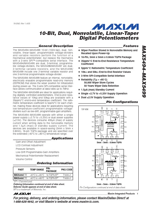
♦ Wiper Position Stored in Nonvolatile Memory and Recalled Upon Power-Up ♦ 16-Pin, 5mm x 5mm x 0.8mm TQFN Package ♦ 35ppm/°C End-to-End Resistance Temperature Coefficient ♦ 5ppm/°C Ratiometric Temperature Coefficient ♦ 10kΩ and 50kΩ End-to-End Resistor Values ♦ 3-Wire SPI-Compatible Serial Interface ♦ Reliability (TA = +85°C) 50,000 Wiper Store Cycles 50 Years Wiper Data Retention ♦ 1.5µA (max) Standby Current ♦ Single +2.7V to +5.25V Supply Operation ♦ Dual ±2.5V Supply Operation
元器件交易网
19-3562; Rev 1; 6/05
10-Bit, Dual, Nonvolatile, Linear-Taper Digital Potentiometers
General Description
The MAX5494–MAX5499 10-bit (1024-tap), dual, nonvolatile, linear-taper, programmable voltage-dividers and variable resistors perform the function of a mechanical potentiometer, but replace the mechanics with a 3-wire SPI™-compatible serial interface. The MAX5494/MAX5495 are dual, 3-terminal, programmable voltage-dividers; the MAX5496/MAX5497 are dual, 2-terminal variable resistors; and the MAX5498/ MAX5499 include one 2-terminal variable resistor and one 3-terminal programmable voltage-divider. The MAX5494–MAX5499 feature an internal, nonvolatile, electrically erasable programmable read-only memory (EEPROM) that stores the wiper position for initialization during power-up. The 3-wire SPI-compatible serial interface allows communication at data rates up to 7MHz. The MAX5494–MAX5499 are ideal for applications requiring digitally controlled potentiometers. End-to-end resistance values of 10kΩ and 50kΩ are available with a 35ppm/°C end-to-end temperature coefficient. The ratiometric temperature coefficient is 5ppm/°C for each channel, making these devices ideal for applications requiring low-temperature-coefficient programmable voltagedividers such as low-drift, programmable-gain amplifiers. The MAX5494–MAX5499 operate with either a single power supply (+2.7V to +5.25V) or dual power supplies (±2.5V). The devices consume 400µA (max) of supply current when writing data to the nonvolatile memory and 1.5µA (max) of standby supply current. The devices are available in space-saving (5mm x 5mm x 0.8mm), 16-pin TQFN package and are specified over the extended (-40°C to +85°C) temperature range.
MAX16809EVKIT+中文资料
General DescriptionThe MAX16809 evaluation kit (EV kit) is a 16-channel,constant-current LED driver, capable of driving 40mA each to 16 LED strings with a total forward voltage of up to 32V. The MAX16809 EV kit is based on the MAX16809 device, which has 16 constant-current-sink-ing outputs with sink current settable using a single resistor and a high-performance, current-mode pulse-width-modulator (PWM) controller, for implementing a DC-DC converter that generates the supply voltage to drive the LED strings.The MAX16809 EV kit operates at supply voltages between 9V to 16V and temperatures ranging from 0°C to +70°C. I t features a PWM dimming control,adaptive control of the LED supply voltage, which depends upon the operating voltage of the LED strings,a built-in clock generator, and a low-current shutdown.The MAX16809 EV kit is a fully assembled and tested board.Features♦9V to 16V Supply Voltage Range♦40mA LED Current (Per Each LED String)♦Single-Resistor Current Adjust for 16 Channels ♦Up to 32V LED String Voltage♦Boost Converter to Generate LED Supply Voltage ♦Adaptive LED Supply Voltage Control Increases Efficiency ♦PWM Dimming Control♦Output-Voltage-Spike Protection for Inductive-Output Lines ♦Proven PCB LayoutEvaluates: MAX16809MAX16809 Evaluation Kit________________________________________________________________Maxim Integrated Products 119-0821; Rev 0; 5/07For pricing, delivery, and ordering information,please contact Maxim/Dallas Direct!at 1-888-629-4642, or visit Maxim’s website at .Ordering Information*This limited temperature range applies to the EV kit PCB only.The MAX16809 IC temperature range is -40°C to +125°C.†EP = Exposed paddle.E v a l u a t e s : M A X 16809MAX16809 Evaluation Kit 2_______________________________________________________________________________________Evaluates: MAX16809MAX16809 Evaluation Kit_______________________________________________________________________________________3Quick StartRecommended Equipment•One 16V, 5A adjustable power supply •One 5V power supply•16 LED strings with a total forward voltage ≤32V •One multimeter•One PWM signal generator (optional)ProcedureThe MAX16809 EV kit is fully assembled and tested.Follow the steps below to verify operation. Caution: Do not turn on the power supply until all connections are completed.1)Connect LED strings with operating voltage ofapproximately 32V between VLED (pins 1-4 of J1)and OUT0–OUT15 (pins 5-20 of J1). All 16 channels should have an LED string load connected of the same type.2)Connect the DC power supply (16V, 5A) to VIN andGND.3)Connect a DC power supply (0 to 5V) to VBIAS andGND.4)Turn on the power supplies and apply 10V to VI Nand 3V to 5V to VBIAS. Connect SHDN and PWM to 3V to 5V. All of the LEDs should turn on. Measure the current through any LED string, which should be 40mA ±7%.5)I ncrease the supply voltage to 16V and the LEDcurrents will be stable. Measure the current through any LED string, which should be 40mA ±7%.6)Apply a PWM signal with amplitude of 3V to 5V anda frequency between 100Hz and 2kHz to the PWM input. The LED brightness should increase as the PWM duty cycle increases and viceversa.7)Connect SHDN to GND and all LEDs should turn off.Detailed DescriptionThe MAX16809 EV kit is a 16-channel, constant-current LED driver capable of driving 40mA each to 16 LED strings, with a total forward voltage of up to 32V. The MAX16809 EV kit can drive a total of 160 white LEDs in 16 strings, with operating current up to 40mA. The MAX16809 EV kit can operate at input supply voltages between 9V and 16V.The MAX16809 EV kit evaluates the MAX16809 IC, which has two major sections. The first section consists of 16constant-current LED drivers capable of sinking up to 55mA when on and blocking up to 36V when off. The sec-ond section is a high-performance current-mode PWMcontroller that can control a DC-DC converter to generate the supply voltage for driving the LED strings. The MAX16809 EV kit uses the PWM controller to drive a boost converter, which takes a 9V to 16V input and gen-erates a 33V LED supply voltage. To drive a constant cur-rent into an LED string, connect the LED string between the 33V output and any of the 16 constant-current-sink outputs. The resistor (R1) from the SET pin to ground pro-grams the sink current of each output. The sink current of any output can be up to 55mA and the amplitude is the same value for all the outputs. The difference between the total forward voltage and the LED supply voltage drops between the constant-current-sink output and ground,and is dissipated as power in the device.The LED supply voltage generated by the boost con-verter in the MAX16809 EV kit is adaptive. The LED string with the highest total forward voltage dominates the control loop, and the boost-converter voltage is adjusted so that the driver associated with that string receives just enough voltage required for current drive.All the other strings, with lower total forward voltages,will have excess supply voltage, which is then dropped in the associated driver. This feedback mechanism ensures that the linear-current-control circuit dissipates the minimum possible power. An on-board inverter (U4A) is configured to generate the clock input for the MAX16809. The constant-current output-driver circuits and U4 need a 3.3V to 5V input, which should be sup-plied externally. If 5V is not available, it can be generat-ed using an emitter-follower buffer from the REF output of MAX16809.Boost ConverterThe boost converter that generates the 33V LED supply voltage operates at a switching frequency of 350kHz in continuous-conduction mode (CCM). The current-mode PWM controller in the MAX16809 drives the external MOSFET (Q2) to control the boost converter. The MOSFET is turned on at the beginning of every switching cycle and turned off when the current through the induc-tor (L1) reaches the peak value set by the error-amplifier-output voltage. Inductor current is sensed from the volt-age across the ground-referenced current-sense resis-tor (parallel combination of R12 and R13). This current-sense information is passed on to the current-sense comparators in the MAX16809 through the CS pin.During the on period of the MOSFET, the inductor stores energy from the input supply. When the switch is turned off, the inductor generates sufficient voltage in reverse direction to discharge the stored energy to VLED. This generated voltage forms a source, in series with the input supply voltage, and drives VLED through the rectifier diode (D2).E v a l u a t e s : M A X 16809MAX16809 Evaluation Kit4_______________________________________________________________________________________As the boost converter is operated in CCM, only part of the stored energy in the inductor is discharged to VLED.The advantages of CCM include reduced input and out-put filtering, reduced EMI due to lower peak currents,and higher converter efficiency. However, these advan-tages come at the cost of a right-half-plane zero in the converter-transfer function. Compensating this zero requires reducing the system bandwidth, which affects the converter-dynamic response. As the 16-channel,constant-current-sink outputs control the current through the LEDs, slower control of VLED does not affect the LED operation. Compensation of the feedback circuit is explained in the Feedback Compensation section.An internal comparator turns off the gate pulse to the external MOSFET if the voltage at the CS pin exceeds 0.3V. The current through the inductor that produces 0.3V at the CS pin is the maximum inductor current possible (the actual current can be a little higher than this limit due to the 60ns propagation delay from the CS pin to the MOSFET drive output). This condition can happen when the feedback loop is broken, when the output capacitor charges during power-up, or when there is an overload at the output. This feature protects the MOSFET by limiting the maximum current passing through it during such conditions.The RC filter, consisting of R9 and C10, removes the voltage spike across the current-sense resistors pro-duced by the turn-on gate current of the MOSFET and the reverse-recovery current of D2. Without filtering,these current spikes can cause sense comparators to falsely trigger and turn off the gate pulse prematurely.The filter time constant should not be higher than required (the MAX16809 EV kit uses a 120ns time con-stant), as a higher time constant adds additional delay to the current-sense voltage, effectively increasing the current limit.During normal operating conditions, the feedback loop controls the peak current. The error amplifier compares a scaled-down version of the LED supply voltage (VLED) with a highly accurate 2.5V reference. The error amplifier and compensation network then amplify the error signal, and the current comparator compares this signal to the sensed-current voltage to create a PWM drive output.Power-Circuit DesignI nitially, decide the input supply voltage range, output voltage VLED (the sum of the maximum LED total for-ward voltage and 1V bias voltage for the constant-cur-rent-sink output), and the output current I OUT (the sum of all the LED string currents).Calculate maximum duty cycle D MAX using the following equation:where V D is the forward drop of the rectifier diode D2(~0.6V), VIN MIN is the minimum input supply voltage (in this case, 9V), and V FET is the average drain-to-source voltage of the MOSFET Q2 when it is on.Select the switching frequency F SW based on the space, noise, dynamic response, and efficiency con-straints. Select the maximum peak-to-peak ripple on the inductor current I L PP . For the MAX16809 EV kit,F SW is 350kHz and IL PP is ±30% of the average induc-tor current. Use the following equations to calculate the maximum average-inductor current I L AVG and peak inductor current IL PEAK :Since I L PP is ±30% of the average-inductor current ILAVG :Calculate the minimum inductance value L MIN with the inductor current ripple set to the maximum value:Choose an inductor that has a minimum inductance greater than this calculated value.Calculate the current-sense resistor (R12 in parallel with R13) using the equation below:where 0.3V is the maximum current-sense signal volt-age. The factor 0.75 is for compensating the reduction of maximum current-sense voltage due to the additionof slope compensation. Check this factor and adjust after the slope compensation is calculated. See the Slope Compensation section for more information.IL IL PP AVG =××032.Evaluates: MAX16809MAX16809 Evaluation Kit_______________________________________________________________________________________5The saturation current limit of the selected inductor (IL SAT ) should be greater than the value given by the equation below. Selecting an inductor with 10% higher IL SAT rating is a good choice:Calculate the output capacitor C OUT (parallel combina-tion of C16, C17, C18, and C24) using the followingequation:where VLED PP is the peak-to-peak ripple in the LED supply voltage. The value of the calculated output capacitance will be much lower than what is actually necessary for feedback loop compensation. See the Feedback Compensation section to calculate the out-put capacitance based on the compensation require-ments.Calculate the input capacitor C IN (parallel combination of C12, C13, C14, and C5) using the following equation:where VI N PP is the peak-to-peak input ripple voltage.This equation assumes that input capacitors supply most of the input ripple current.Selection of Power SemiconductorsThe switching MOSFET (Q2) should have a voltage rat-ing sufficient to withstand the maximum output voltage,together with the diode drop of D2, and any possible overshoot due to ringing caused by parasitic induc-tances and capacitances. Use a MOSFET with voltage rating higher than that calculated by the following equation:The factor of 1.3 provides a 30% safety margin.The continuous drain-current rating of the selected MOSFET when the case temperature is at +70°C should be greater than that calculated by the following equation.The MOSFET must be mounted on a board, as per manufacturer specifications, to dissipate the heat:The MOSFET dissipates power due to both switchinglosses, as well as conduction losses. Use the following equation to calculate the conduction losses in the MOSFET:where RDS ON is the on-state drain-source resistance of the MOSFET with an assumed junction temperature of 100°C.Use the following equation to calculate the switching losses in the MOSFET:where I GON and I GOFF are the gate currents of the MOSFET (with V GS equal to the threshold voltage)when it is turned on and turned off, respectively, and C GD is the gate-to-drain MOSFET capacitance. Choose a MOSFET that has a higher power rating than that cal-culated by the following equation when the MOSFET case temperature is at +70°C:The MAX16809 EV kit uses a Schottky diode as the boost-converter rectifier (D2). A Schottky rectifier diode produces less forward drop and puts the least burden on the MOSFET during reverse recovery. If a diode with considerable reverse-recovery time is used, it should be considered in the MOSFET switching-loss calculation.The Schottky diode selected should have a voltage rat-ing 20% above the maximum boost-converter output voltage. The current rating of the diode should be greater than I Din the following equation:P P P TOT COND SW=+V VLED V DS D =+()×13.IL IL SAT PEAK=×11.E v a l u a t e s : M A X 16809MAX16809 Evaluation Kit 6_______________________________________________________________________________________Slope CompensationWhen the boost converter operates in CCM with more than 50% duty cycle, subharmonic oscillations occur if slope compensation is not implemented. Subharmonic oscillations do not allow the PWM duty cycle to settle to a peak current value set by the voltage-feedback loop.The duty cycle oscillates back and forth about the required value, usually at half the switching frequency.Subharmonic oscillations die out if a sufficient negative slope is added to the inductor peak current. This means that for any peak current set by the feedback loop, the output pulse terminates sooner than normally expected. The minimum slope compensation that should be added to stabilize the current loop is half of the worst-case (max) falling slope of inductor current.Adding a ramp to the current-sense signal, with posi-tive slope in sync with the switching frequency, can produce the desired function. The greater the duty cycle, the greater the added voltage, and the greater the difference between the set current and the actual inductor current. In the MAX16809 EV kit, the oscillator ramp signal is buffered using Q1 and added to the cur-rent-sense signal with proper scaling to implement the slope compensation. Follow the steps below to calcu-late the component values for slope compensation.Calculate the worst-case falling slope of the inductor current using the following equation:From the inductor current falling slope, find its equiva-lent voltage slope across the current-sense resistor R CS (R12 parallel with R13) using the following equation:The minimum voltage slope that should be added to the current-sense waveform is half of V SLOPE for ensur-ing stability up to 100% duty cycle. As the maximum continuous duty cycle used is less than 100%, the mini-mum required compensation slope becomes:The factor 1.1 provides a 10% margin. Resistors R9and R10 determine the attenuation of the buffered volt-age slope from the emitter of Q1. The forward drop ofsignal diode D11, together with the V BE of Q1, almost cancel the 1.1V offset of the ramp waveform. Calculate the approximate slope of the oscillator ramp using the following equation:where 1.7V is the ramp amplitude and F SW is the switching frequency.Select the value of R9 such that the input bias current of the current-sense comparators does not add consider-able error to the current-sense signal. The value of R10for the slope compensation is given by the equation:LED DriverThe MAX16809 features a 16-channel, constant-current LED driver, with each channel capable of sinking up to 55mA of LED current. The LED strings are connected between VLED and the constant-current-sink outputs to drive regulated current through LED strings. The cur-rent through all 16 channels is controlled through resis-tor (R1) from the SET pin to ground. The MAX16809 EV kit sets the current through each string at 40mA and the maximum LED supply voltage to 33V. The MAX16809EV kit drives LED strings with a total forward voltage of up to 32V.A 4-wire serial interface with four inputs (DIN, CLK, LE,and OE ) individually control the constant-current out-puts. I n the MAX16809 EV kit, a 50kHz clock signal,generated by U4A, clocks 16 1s into the internal shift register by tying DIN and LE to 5V. The clock-generation circuit can be avoided if a microcontroller provides the function.The output enable (OE ) can provide PWM dimming. An inverted PWM signal, generated by the inverter U4B, is necessary to drive the OE pin. When the PWM signal is low (LED drivers off), it also influences the feedback with the network formed by R6 and D12. See the Adaptive LED Supply Voltage Control section for more details.I f an inverted PWM signal is available, use the circuit shown in Figure1 to drive the OE input and feedbacknetwork.VR F SLOPE SW=×17.V IL R SLOPE SLOPE CS=×Evaluates: MAX16809MAX16809 Evaluation Kit_______________________________________________________________________________________7Output Current SettingThe amplitude of the output sink currents for all 16channels is set to the same value by the resistor (R1)from the SET pin to ground. The minimum allowed value of R SET is 311Ω, which sets the output currents to 55mA. The maximum allowed value of R SET is 5k Ω. The MAX16809 EV kit uses 430Ωfor R SET , which sets the output current to 40mA. To set a different output cur-rent, use the following equation:where R SET is the current-setting resistor (R1) value in ohms and I OUT is the desired output current in milliamps.Adaptive LED Supply Voltage ControlTo reduce power dissipation in the I C, the MAX16809EV kit features adaptive control of VLED based on the operating voltage of the LED strings. The constant-cur-rent-sink outputs can sink stable currents with output voltages as low as 0.8V. The voltage at each of the 16outputs will be the difference between VLED and the total forward voltage of the LED string connected to that output. The MAX16809 EV kit implements a feed-back mechanism to sense the voltage at each of the 16constant-current-sink outputs. Using dual zener diodes (D3–D10), the MAX16809 EV kit selects the lowest dri-ver voltage (with the greatest LED string voltage) to regulate. The boost-converter PWM then adjusts so that VLED is high enough for this sink output to settle toapproximately 0.8V. All the other strings have sufficient voltage, as their total forward voltages are lower. The feedback mechanism ensures that the IC dissipates the minimum possible power. For adaptive control to func-tion efficiently connect LED strings to all 16 channels and use an equal number of LEDs from the same bin in each string. I f some of the 16 channels are not used,then the zener diodes (D3–D10) should be removed from the unused channels.Use the equation below to calculate the value of R2 to get the required minimum voltage at the sink outputs:where 2.5V is the feedback reference, V DZ is the for-ward drop of the ORing diode (D3–D10), V S = 0.5V is the required sink-output voltage, and V FLED is the nom-inal total forward voltage of the LED strings. Select the value of R2 such that R7 is approximately 10k Ω.The zener diodes (D3–D10) also provide output over-voltage protection. If an LED string gets partially or fully shorted, making the sink-output voltage go high, the 15V zener diode connected to that output conducts in reverse direction, and limits the VLED voltage. Under this condition, the other LED strings might not turn on.When the outputs are off, the LED drivers are at high impedance and the feedback network now combines R6 and D12 to provide a path for the feedback currentand to control VLED. Use the following equation toE v a l u a t e s : M A X 16809MAX16809 Evaluation Kit 8_______________________________________________________________________________________calculate the value of R6 to get the required LED sup-ply voltage during PWM off time:where 2.5V is the feedback-reference voltage, 0.4V is the total voltage dropped by D4 and PWM input, and VLED OFF is the desired LED supply voltage during PWM off time. VLED OFF should be set to the worst-case LED string voltage plus some additional headroom for the LED drivers (0.8V), as well as a reserve voltage (approximately 1V). The reserve voltage allows the MAX16809 to provide current for very short PWM dim-ming on-pulses. With pulses as low as 2µs, the VLED control loop is not able to react, and the output capaci-tors provide all the current. For longer PWM dimming pulses, the control loop reacts and the supply operates at the adaptive voltage level.During an open LED condition, the 33V zener diode (D1) limits the maximum LED supply voltage to 35.5V. If VLED attempts to increase beyond this level, D1 con-ducts in reverse direction and pulls the FB pin high,which causes the boost regulator to cut back on the PWM signal and reduce the output voltage.PWM DimmingThe PWM dimming controls the LED brightness by adjusting the duty cycle of the PWM input signal. A high voltage at the PWM input enables the output cur-rent; a low voltage turns off the output current. Connect a signal with peak amplitude of 3V to 5V and with fre-quency from 100Hz to 2kHz to the PWM input and vary the duty cycle to adjust the LED brightness. The LED brightness increases when the duty cycle increases and vice versa. If an inverted PWM signal is available,use that signal to implement PWM dimming, as shown in Figure 1.Feedback CompensationLike any other circuit with feedback, the boost convert-er that generates the supply voltage for the LED strings needs to be compensated for stable control of its out-put voltage. As the boost converter is operated in con-tinuous-conduction mode, there exists a right-half-plane (RHP) zero in the power-circuit transfer function.This zero adds a 20dB/decade gain together with a 90-degree phase lag, which is difficult to compensate. The easiest way to avoid this zero is to roll off the loop gainto 0dB at a frequency less than half of the RHP zero fre-quency with a -20dB/decade slope. For a boost con-verter, the worst-case RHP zero frequency (F ZRHP ) is given by the following equation:where D MAX is the maximum duty cycle, L is the induc-tance of the inductor, and I O is the output current,which is the sum of all the LED string currents.The boost converter used in the MAX16809 EV kit is operated with current-mode control. There are two feedback loops within a current-mode-controlled con-verter: an inner loop that controls the inductor current and an outer loop that controls the output voltage. The amplified voltage error produced by the outer voltage loop is the input to the inner current loop that controls the peak inductor current.The internal current loop converts the double-pole 2nd-order system, formed by the inductor and the output capacitor C OUT , to a 1st-order system having a single pole consisting of the output filter capacitor and the out-put load. As the output load is a constant current (i.e.,very high Thevenin impedance), this pole is located near the origin (0Hz). The phase lag created by the output pole for any frequency will be 90 degrees. Since the power-circuit DC gain is limited by other factors, the gain starts falling at -20dB/decade from a non-zero frequency before which the power-circuit gain stabilizes.Total gain of the feedback loop at DC is given by the following equation:where G P is the power-circuit DC gain, and G EA is the error-amplifier open-loop DC gain, typically 100dB. G FB is the gain of the feedback network for adaptive control of the VLED, which is seen from VLED to the error-amplifier input (FB pin). The adaptive control senses the voltages at the 16 constant-current-sink outputs and adjusts the feedback to control these voltages to a minimum value (Figure 2). As the LEDs carry constant current, the voltage across the LEDs does not change with variations in VLED. Any change in VLED directly reflects to the constant-current-sink outputs and to the error-amplifier input, making G FB equal to unity.G G G G TOT P EA FB=××Evaluates: MAX16809MAX16809 Evaluation Kit_______________________________________________________________________________________9The DC gain of the power circuit is expressed as the change in the output voltage, with respect to the change in error-amplifier output voltage. As the boost converter in the MAX16809 EV kit drives a constant-current load, the power-circuit DC gain is calculatedCalculate the power-circuit DC gain using the following where R CS is the current-sense resistor, F SW is theswitching frequency, and the factor 3 is to account for the attenuation of error-amp output before it is fed to the current-sense comparator.The power-circuit gain is lowest at the minimum input supply voltage and highest at the maximum input sup-ply voltage. Any input supply voltage between 9V and 16V can be used for power-circuit gain calculation, as the final compensation values obtained are the same.Calculate the frequency F P2,at which the power-circuit gain starts falling,at -20dB/decade using the following equation:where C OUT is the output filter capacitor, which is the parallel combination of C16, C17, C18, and C24. Adjust the output capacitance so that the product of F P2and G P is below F ZRHP / 6. The value of output capacitance obtained this way will be much greater than the value obtained using the maximum output voltage ripple specification.The compensation strategy is as follows. The gain-fre-quency response of the feedback loop should cross 0dB at or below half of the RHP zero frequency, with a slope of -20dB/decade for the feedback to be stable and have sufficient phase margin. The compensation network from COMP pin to FB pin of the MAX16809 (formed by R5,C28, C29, and R11) offers one dominant pole (P1), a zero (Z1), and a high-frequency pole (P3). There are two very low frequency poles and a zero in the loop before the crossover frequency. The function of the zero (Z1) is to compensate for the output pole and to reduce the slope of the loop gain from -40dB/decade to -20dB/decade,and also to reduce the phase lag by 90 degrees.Choose the crossover frequency to be half of the worst-case RHP zero frequency:Place the zero (Z1) at one-third of the crossover fre-quency, so that the phase margin starts improving from a sufficiently lower frequency:Use the following equation to calculate the dominant pole location, so that the loop gain crosses 0dB at F C :Since the open-loop gain of the error amplifier can have variations, the dominant pole location can also vary from device to device. I n the MAX16809 EV kit, the dominant pole location is decided by the error-amplifier gain, so the combined effect is a constant-gain-band-width product.Select the value of R11 such that the input bias current of the error amplifier does not cause considerable drop across it. The effective AC impedance seen from the FB pin is the sum of R11 and R7. I t is preferable to keep R7 much lower, compared to R11, to have better control on the AC impedance. Find C29 using the fol-lowing equation:The location of the zero (Z1) decided by R5 and C29 is given by the following equation:Place the high-frequency pole (P 3), formed by C28,C29, and R5, at half the switching frequency to provide further attenuation to any high-frequency signal propa-gating through the system. The location of the high-fre-quency pole (F P3) is given by the following equation,and should be used to calculate the value of C28:。
TLC549IP;TLC549CP;TLC549CD;TLC548CP;TLC549ID;中文规格书,Datasheet资料

TLC548C, TLC548I, TLC549C, TLC549I 8-BIT ANALOG-TO-DIGITAL CONVERTERSWITH SERIAL CONTROLSLAS067C – NOVEMBER 1983 – REVISED SEPTEMBER 19961POST OFFICE BOX 655303 •DALLAS, TEXAS 75265D Microprocessor Peripheral or Standalone OperationD 8-Bit Resolution A/D ConverterD Differential Reference Input Voltages D Conversion Time ...17 µs MaxDTotal Access and Conversion Cycles Per Second– TLC548...up to 45500– TLC549...up to 40000D On-Chip Software-Controllable Sample-and-Hold FunctionD Total Unadjusted Error ...±0.5 LSB Max D 4-MHz Typical Internal System Clock D Wide Supply Range ...3V to 6VD Low Power Consumption ...15mW Max D Ideal for Cost-Effective, High-Performance Applications including Battery-Operated Portable InstrumentationDPinout and Control Signals Compatible With the TLC540 and TLC545 8-Bit A/D Converters and with the TLC1540 10-Bit A/D ConverterDCMOS TechnologydescriptionThe TLC548 and TLC549 are CMOS analog-to-digital converter (ADC) integrated circuits built around an 8-bit switched-capacitor successive-approximation ADC. These devices are designed for serial interface with a microprocessor or peripheral through a 3-state data output and an analog input. The TLC548 and TLC549 use only the input/output clock (I/O CLOCK) input along with the chip select (CS) input for data control. The maximum I/O CLOCK input frequency of the TLC548 is 2.048 MHz, and the I/O CLOCK input frequency of the TLC549 is specified up to 1.1 MHz.AVAILABLE OPTIONSPACKAGET A SMALL OUTLINE(D)PLASTIC DIP(P)0°C to 70°C TLC548CD TLC549CD TLC548CP TLC549CP –40°C to 85°CTLC548ID TLC549IDTLC548IP TLC549IPCopyright © 1996, Texas Instruments IncorporatedPRODUCTION DATA information is current as of publication date.Products conform to specifications per the terms of Texas Instruments standard warranty. Production processing does not necessarily include testing of all parameters.Please be aware that an important notice concerning availability, standard warranty, and use in critical applications of Texas Instruments semiconductor products and disclaimers thereto appears at the end of this data sheet.12348765REF+ANALOG INREF–GNDV CCI/O CLOCK DATA OUT CSD OR P PACKAGE(TOP VIEW)TLC548C, TLC548I, TLC549C, TLC549I 8-BIT ANALOG-TO-DIGITAL CONVERTERS WITH SERIAL CONTROLSLAS067C – NOVEMBER 1983 – REVISED SEPTEMBER 19962POST OFFICE BOX 655303 •DALLAS, TEXAS 75265description (continued)Operation of the TLC548 and the TLC549 is very similar to that of the more complex TLC540 and TLC541devices; however, the TLC548 and TLC549 provide an on-chip system clock that operates typically at 4 MHz and requires no external components. The on-chip system clock allows internal device operation to proceed independently of serial input/output data timing and permits manipulation of the TLC548 and TLC549 as desired for a wide range of software and hardware requirements. The I/O CLOCK together with the internal system clock allow high-speed data transfer and conversion rates of 45500 conversions per second for the TLC548, and 40000 conversions per second for the TLC549.Additional TLC548 and TLC549 features include versatile control logic, an on-chip sample-and-hold circuit that can operate automatically or under microprocessor control, and a high-speed converter with differential high-impedance reference voltage inputs that ease ratiometric conversion, scaling, and circuit isolation from logic and supply noises. Design of the totally switched-capacitor successive-approximation converter circuit allows conversion with a maximum total error of ±0.5 least significant bit (LSB) in less than 17 µs.The TLC548C and TLC549C are characterized for operation from 0°C to 70°C. The TLC548I and TLC549I are characterized for operation from –40°C to 85°C.functional block diagramREF –6488DATAOUT8-Bit Analog-to Digital Converter (Switched-Capacitors)8-to-1 Data Selector and DriverOutput Data RegiserInternal System ClockSample and Hold75231ANALOG INREF +CSI/O CLOCKControl Logic and Output Countertypical equivalent inputsINPUT CIRCUIT IMPEDANCE DURING SAMPLING MODEINPUT CIRCUIT IMPEDANCE DURING HOLD MODE1 k Ω TYPC i = 60 pF TYP (equivalent input capacitance)5 M Ω TYPANALOG INANALOG INTLC548C, TLC548I, TLC549C, TLC549I 8-BIT ANALOG-TO-DIGITAL CONVERTERSWITH SERIAL CONTROLSLAS067C – NOVEMBER 1983 – REVISED SEPTEMBER 19963POST OFFICE BOX 655303 •DALLAS, TEXAS 75265operating sequencet ent ent su(CS)B7B0B1B2B3B4B5B6B7Conversion Data BMSB MSB LSBHi-Z StateMSBLSB (see Note B)MSB Previous Conversion Data AA7A7A6A5A4A3A2A1A0Hi-Z StateDon’t11(see Note A)t conv t su(CS)Access Cycle B88765432765432CLOCK I/O CSOUTDATA CareSample Cycle BAccess Cycle CSample Cycle Ct wH(CS)NOTES: A.The conversion cycle, which requires 36 internal system clock periods (17 µs maximum), is initiated with the eighth I/O clock pulsetrailing edge after CS goes low for the channel whose address exists in memory at the time.B.The most significant bit (A7) is automatically placed on the DATA OUT bus after CS is brought low. The remaining seven bits (A6–A0)are clocked out on the first seven I/O clock falling edges. B7–B0 follows in the same manner.absolute maximum ratings over operating free-air temperature range (unless otherwise noted)Supply voltage, V CC (see Note 1) 6.5 V . . . . . . . . . . . . . . . . . . . . . . . . . . . . . . . . . . . . . . . . . . . . . . . . . . . . . . . . . . Input voltage range at any input –0.3 V to V CC + 0.3 V . . . . . . . . . . . . . . . . . . . . . . . . . . . . . . . . . . . . . . . . . . . . . Output voltage range –0.3 V to V CC + 0.3 V . . . . . . . . . . . . . . . . . . . . . . . . . . . . . . . . . . . . . . . . . . . . . . . . . . . . . . Peak input current range (any input) ±10 mA . . . . . . . . . . . . . . . . . . . . . . . . . . . . . . . . . . . . . . . . . . . . . . . . . . . . . Peak total input current range (all inputs) ±30 mA . . . . . . . . . . . . . . . . . . . . . . . . . . . . . . . . . . . . . . . . . . . . . . . . . Operating free-air temperature range, T A (see Note 2): TLC548C, TLC549C 0°C to 70°C. . . . . . . . . . . . . TLC548I, TLC549I –40°C to 85°C. . . . . . . . . . . . Storage temperature range, T stg –65°C to 150°C . . . . . . . . . . . . . . . . . . . . . . . . . . . . . . . . . . . . . . . . . . . . . . . . . . Lead temperature 1,6 mm (1/16 inch) from case for 10 seconds 260°C. . . . . . . . . . . . . . . . . . . . . . . . . . . . . . . NOTES: 1.All voltage values are with respect to the network ground terminal with the REF– and GND terminals connected together, unlessotherwise noted.2.The D package is not recommended below –40°C.TLC548C, TLC548I, TLC549C, TLC549I 8-BIT ANALOG-TO-DIGITAL CONVERTERS WITH SERIAL CONTROLSLAS067C – NOVEMBER 1983 – REVISED SEPTEMBER 19964POST OFFICE BOX 655303 •DALLAS, TEXAS 75265recommended operating conditionsTLC548TLC549MINNOMMAXMIN NOMMAXUNIT Supply voltage, V CC356356V Positive reference voltage, V ref+ (see Note 3) 2.5V CC V CC +0.12.5V CC V CC +0.1V Negative reference voltage, V ref – (see Note 3)–0.10 2.5–0.10 2.5V Differential reference voltage, V ref+, V ref – (see Note 3)1V CC V CC +0.21V CC V CC +0.2V Analog input voltage (see Note 3)0V CC0V CCV High-level control input voltage, V IH (for V CC = 4.75 V to 5.5 V)22V Low-level control input voltage, V IL (for V CC = 4.75 V to 5.5 V)0.80.8V Input/output clock frequency, f clock(I/O) (for V CC = 4.75 V to 5.5 V)0 2.0480 1.1MHz Input/output clock high, t wH(I/O) (for V CC = 4.75 V to 5.5 V)200404ns Input/output clock low, t wL(I/O) (for V CC = 4.75 V to 5.5 V)200404ns Input/output clock transition time, t t(I/O)(for V CC = 4.75 V to 5.5 V) (see Note 4 and Operating Sequence)100100ns Duration of CS input high state during conversion, t wH(CS)(for V CC = 4.75 V to 5.5 V) (see Operating Sequence)1717µs Setup time, CS low before first I/O CLOCK, t su(CS) (for V CC = 4.75 V to 5.5 V) (see Note 5) 1.4 1.4µs TLC548C, TLC549C 070070CTLC548I, TLC549I–4085–4085°NOTES: 3.Analog input voltages greater than that applied to REF+ convert to all ones (11111111), while input voltages less than that appliedto REF– convert to all zeros (00000000). For proper operation, the positive reference voltage V ref+, must be at least 1 V greater than the negative reference voltage, V ref–. In addition, unadjusted errors may increase as the differential reference voltage, V ref+ – V ref–,falls below 4.75 V.4.This is the time required for the I/O CLOCK input signal to fall from V IH min to V IL max or to rise from V IL max to V IH min. In the vicinityof normal room temperature, the devices function with input clock transition time as slow as 2 µs for remote data acquisition applications in which the sensor and the ADC are placed several feet away from the controlling microprocessor.5.To minimize errors caused by noise at the CS input, the internal circuitry waits for two rising edges and one falling edge of internalsystem clock after CS ↓ before responding to control input signals. This CS setup time is given by the t en and t su(CS) specifications.TLC548C, TLC548I, TLC549C, TLC549I 8-BIT ANALOG-TO-DIGITAL CONVERTERSWITH SERIAL CONTROLSLAS067C – NOVEMBER 1983 – REVISED SEPTEMBER 19965POST OFFICE BOX 655303 •DALLAS, TEXAS 75265electrical characteristics over recommended operating free-air temperature range,V CC = V ref+ = 4.75 V to 5.5 V, f clock(I/O) = 2.048 MHz for TLC548 or 1.1 MHz for TLC549 (unless otherwise noted)PARAMETERTEST CONDITIONS MIN TYP †MAXUNIT V OH High-level output voltage V CC = 4.75 V,I OH = –360 µA 2.4V V OL Low-level output voltageV CC = 4.75 V,I OL = 3.2 mA 0.4V I OZ High impedance off state output current V O = V CC ,CS at V CC 10High-impedance off-state output current V O = 0,CS at V CC–10µA I IH High-level input current, control inputs V I = V CC 0.005 2.5µA I IL Low-level input current, control inputsV I = 0–0.005–2.5µA I I()Analog channel on-state input current during sample Analog input at V CC 0.41I(on)g g cycleAnalog input at 0 V –0.4–1µA I CCOperating supply current CS at 0 V 1.8 2.5mA I CC + I ref Supply and reference current V ref+ = V CC1.93mA Input capacitance Analog inputs 755C iInput capacitanceControl inputs515pFoperating characteristics over recommended operating free-air temperature range, V CC = V ref+ = 4.75 V to 5.5 V, f clock(I/O) = 2.048 MHz for TLC548 or 1.1 MHz for TLC549 (unless otherwise noted)TEST CONDITIONS TLC548TLC549PARAMETERTEST CONDITIONS MINTYP †MAX MIN TYP †MAX UNIT E L Linearity error See Note 6±0.5±0.5LSB E ZS Zero-scale error See Note 7±0.5±0.5LSB E FS Full-scale error See Note 7±0.5±0.5LSB Total unadjusted error See Note 8±0.5±0.5LSB t convConversion timeSee Operating Sequence 8171217µs Total access and conversion timeSee Operating Sequence 12221925µs t a Channel acquisition time (sample cycle)See Operating Sequence44I/O clock cycles t v Time output data remains valid after I/O CLOCK ↓1010nst d Delay time to data output valid I/O CLOCK ↓200400ns t en Output enable time 1.4 1.4µs t dis Output disable time 150150ns t r(bus)Data bus rise timeSee Figure 1300300nst f(bus)Data bus fall time 300300ns †All typicals are at V CC = 5 V, T A = 25°C.NOTES: 6.Linearity error is the deviation from the best straight line through the A/D transfer characteristics.7.Zero-scale error is the difference between 00000000 and the converted output for zero input voltage; full-scale error is the differencebetween 11111111 and the converted output for full-scale input voltage.8.Total unadjusted error is the sum of linearity, zero-scale, and full-scale errors.TLC548C, TLC548I, TLC549C, TLC549I 8-BIT ANALOG-TO-DIGITAL CONVERTERS WITH SERIAL CONTROLSLAS067C – NOVEMBER 1983 – REVISED SEPTEMBER 19966POST OFFICE BOX 655303 •DALLAS, TEXAS 75265PARAMETER MEASUREMENT INFORMATIONSee Note B0.4 V2.4 V t f(bus)Outputt r(bus)0.8 V2.4 V 0.8 Vt dDATA OUTVOLTAGE WAVEFORMS FOR RISE AND FALL TIMESVOLTAGE WAVEFORMS FOR DELAY TIMEV CC3 k Ω3 k ΩV CCSee Note B 50%50%0 V0 Vt PLZI/O CLOCKVOLTAGE WAVEFORMS FOR ENABLE AND DISABLE TIMESOutput Waveform 1(see Note C)t PHZV OH 90%10%t PZL0 VV CC 50%CSLOAD CIRCUIT FOR t PZL AND t PLZLOAD CIRCUIT FOR t PZH AND t PHZLOAD CIRCUIT FORt d , t r , AND t fSee Note BOutput Under Test Test Point3 k Ω1.4 VOutput Waveform 2(see Note C)C L(see Note A)Output Under Test Test Point C L(see Note A)Output Under Test Test PointC L(see Note A)t PZH50%NOTES: A.C L = 50 pF for TLC548 and 100 pF for TLC549; C L includes jig capacitance.B.t en = t PZH or t PZL , t dis = t PHZ or t PLZ .C.Waveform 1 is for an output with internal conditions such that the output is low except when disabled by the output control.Waveform 2 is for an output with internal conditions such that the output is high except when disabled by the output control.Figure 1. Load Circuits and Voltage WaveformsTLC548C, TLC548I, TLC549C, TLC549I 8-BIT ANALOG-TO-DIGITAL CONVERTERSWITH SERIAL CONTROLSLAS067C – NOVEMBER 1983 – REVISED SEPTEMBER 19967POST OFFICE BOX 655303 •DALLAS, TEXAS 75265APPLICATIONS INFORMATIONsimplified analog input analysisUsing the equivalent circuit in Figure 2, the time required to charge the analog input capacitance from 0 to V S within 1/2 LSB can be derived as follows:The capacitance charging voltage is given byV C = V S 1–e–t c /R t C i ( )(1)whereR t = R s + r iThe final voltage to 1/2 LSB is given by(2)V C (1/2 LSB) = V S – (V S /512)Equating equation 1 to equation 2 and solving for time t c givesV S –(V S /512) = V S 1–e(3)–t c /R t C i( )andt c (1/2 LSB) = R t × C i × ln(512)(4)Therefore, with the values given the time for the analog input signal to settle ist c (1/2 LSB) = (R s + 1 k Ω) × 60 pF × ln(512)(5)This time must be less than the converter sample time shown in the timing diagrams.R sr i V SV C 1 k Ω MAXDriving Source †TLC548/9V IV I = Input Voltage at ANALOG IN V S = External Driving Source Voltage R s = Source Resistance r i = Input Resistance C i = Input Capacitance†Driving source requirements:•Noise and distortion for the source must be equivalent to the resolution of the converter.•R s must be real at the input frequency.C i55 pF MAX Figure 2. Equivalent Input Circuit Including the Driving SourceTLC548C, TLC548I, TLC549C, TLC549I 8-BIT ANALOG-TO-DIGITAL CONVERTERS WITH SERIAL CONTROLSLAS067C – NOVEMBER 1983 – REVISED SEPTEMBER 19968POST OFFICE BOX 655303 •DALLAS, TEXAS 75265PRINCIPLES OF OPERATIONThe TLC548 and TLC549 are each complete data acquisition systems on a single chip. Each contains an internal system clock, sample-and-hold function, 8-bit A/D converter, data register, and control logic circuitry. For flexibility and access speed, there are two control inputs: I/O CLOCK and chip select (CS). These control inputs and a TTL-compatible 3-state output facilitate serial communications with a microprocessor or minicomputer. A conversion can be completed in 17 µs or less, while complete input-conversion-output cycles can be repeated in 22 µs for the TLC548 and in 25 µs for the TLC549.The internal system clock and I/O CLOCK are used independently and do not require any special speed or phase relationships between them. This independence simplifies the hardware and software control tasks for the device.Due to this independence and the internal generation of the system clock, the control hardware and software need only be concerned with reading the previous conversion result and starting the conversion by using the I/O clock. In this manner, the internal system clock drives the “conversion crunching” circuitry so that the control hardware and software need not be concerned with this task.When CS is high, DATA OUT is in a high-impedance condition and I/O CLOCK is disabled. This CS control function allows I/O CLOCK to share the same control logic point with its counterpart terminal when additional TLC548 and TLC549 devices are used. This also serves to minimize the required control logic terminals when using multiple TLC548 and TLC549 devices.The control sequence has been designed to minimize the time and effort required to initiate conversion and obtain the conversion result. A normal control sequence is:1.CS is brought low. To minimize errors caused by noise at CS, the internal circuitry waits for two rising edgesand then a falling edge of the internal system clock after a CS ↓ before the transition is recognized. However,upon a CS rising edge, DATA OUT goes to a high-impedance state within the specified t dis even though the rest of the integrated circuitry does not recognize the transition until the specified t su(CS) has elapsed. This technique protects the device against noise when used in a noisy environment. The most significant bit (MSB)of the previous conversion result initially appears on DATA OUT when CS goes low.2.The falling edges of the first four I/O CLOCK cycles shift out the second, third, fourth, and fifth most significantbits of the previous conversion result. The on-chip sample-and-hold function begins sampling the analog input after the fourth high-to-low transition of I/O CLOCK. The sampling operation basically involves the charging of internal capacitors to the level of the analog input voltage.3.Three more I/O CLOCK cycles are then applied to the I/O CLOCK terminal and the sixth, seventh, and eighthconversion bits are shifted out on the falling edges of these clock cycles.4.The final (the eighth) clock cycle is applied to I/O CLOCK. The on-chip sample-and-hold function begins thehold operation upon the high-to-low transition of this clock cycle. The hold function continues for the next four internal system clock cycles, after which the holding function terminates and the conversion is performed during the next 32 system clock cycles, giving a total of 36 cycles. After the eighth I/O CLOCK cycle, CS must go high or the I/O clock must remain low for at least 36 internal system clock cycles to allow for the completion of the hold and conversion functions. CS can be kept low during periods of multiple conversion. When keeping CS low during periods of multiple conversion, special care must be exercised to prevent noise glitches on the I/O CLOCK line. If glitches occur on I/O CLOCK, the I/O sequence between the microprocessor/controller and the device loses synchronization. When CS is taken high, it must remain high until the end of conversion. Otherwise, a valid high-to-low transition of CS causes a reset condition, which aborts the conversion in progress.A new conversion may be started and the ongoing conversion simultaneously aborted by performing steps 1 through 4 before the 36 internal system clock cycles occur. Such action yields the conversion result of the previous conversion and not the ongoing conversion.TLC548C, TLC548I, TLC549C, TLC549I 8-BIT ANALOG-TO-DIGITAL CONVERTERSWITH SERIAL CONTROLSLAS067C – NOVEMBER 1983 – REVISED SEPTEMBER 19969POST OFFICE BOX 655303 •DALLAS, TEXAS 75265PRINCIPLES OF OPERATIONFor certain applications, such as strobing applications, it is necessary to start conversion at a specific point in time.This device accommodates these applications. Although the on-chip sample-and-hold function begins sampling upon the high-to-low transition of the fourth I/O CLOCK cycle, the hold function does not begin until the high-to-low transition of the eighth I/O CLOCK cycle, which should occur at the moment when the analog signal must be converted. The TLC548 and TLC549 continue sampling the analog input until the high-to-low transition of the eighth I/O CLOCK pulse. The control circuitry or software then immediately lowers I/O CLOCK and starts the holding function to hold the analog signal at the desired point in time and starts the conversion.PACKAGING INFORMATIONOrderableDeviceStatus (1)Package Type Package DrawingPins Package Qty Eco Plan (2)Lead/Ball Finish MSL Peak Temp (3)TLC548CD ACTIVE SOIC D 875Green (RoHS &no Sb/Br)CU NIPDAU Level-1-260C-UNLIM TLC548CDG4ACTIVE SOIC D 875Green (RoHS &no Sb/Br)CU NIPDAU Level-1-260C-UNLIM TLC548CDR ACTIVE SOIC D 82500Green (RoHS &no Sb/Br)CU NIPDAU Level-1-260C-UNLIM TLC548CDRG4ACTIVE SOIC D 82500Green (RoHS &no Sb/Br)CU NIPDAU Level-1-260C-UNLIM TLC548CP ACTIVE PDIP P 850Pb-Free (RoHS)CU NIPDAU N /A for Pkg Type TLC548CPE4ACTIVE PDIP P 850Pb-Free (RoHS)CU NIPDAU N /A for Pkg Type TLC548ID ACTIVE SOIC D 875Green (RoHS &no Sb/Br)CU NIPDAU Level-1-260C-UNLIM TLC548IDG4ACTIVE SOIC D 875Green (RoHS &no Sb/Br)CU NIPDAU Level-1-260C-UNLIM TLC548IDR ACTIVE SOIC D 82500Green (RoHS &no Sb/Br)CU NIPDAU Level-1-260C-UNLIM TLC548IDRG4ACTIVE SOIC D 82500Green (RoHS &no Sb/Br)CU NIPDAU Level-1-260C-UNLIM TLC548IP ACTIVE PDIP P 850Pb-Free (RoHS)CU NIPDAU N /A for Pkg Type TLC548IPE4ACTIVE PDIP P 850Pb-Free (RoHS)CU NIPDAU N /A for Pkg Type TLC549CD ACTIVE SOIC D 875Green (RoHS &no Sb/Br)CU NIPDAU Level-1-260C-UNLIM TLC549CDG4ACTIVE SOIC D 875Green (RoHS &no Sb/Br)CU NIPDAU Level-1-260C-UNLIM TLC549CDR ACTIVE SOIC D 82500Green (RoHS &no Sb/Br)CU NIPDAU Level-1-260C-UNLIM TLC549CDRG4ACTIVE SOIC D 82500Green (RoHS &no Sb/Br)CU NIPDAU Level-1-260C-UNLIM TLC549CP ACTIVE PDIP P 850Pb-Free (RoHS)CU NIPDAU N /A for Pkg Type TLC549CPE4ACTIVE PDIP P 850Pb-Free (RoHS)CU NIPDAU N /A for Pkg Type TLC549ID ACTIVE SOIC D 875Green (RoHS &no Sb/Br)CU NIPDAU Level-1-260C-UNLIM TLC549IDG4ACTIVE SOIC D 875Green (RoHS &no Sb/Br)CU NIPDAU Level-1-260C-UNLIM TLC549IDR ACTIVE SOIC D 82500Green (RoHS &no Sb/Br)CU NIPDAU Level-1-260C-UNLIM TLC549IDRG4ACTIVE SOIC D 82500Green (RoHS &no Sb/Br)CU NIPDAU Level-1-260C-UNLIM TLC549IP ACTIVE PDIP P 850Pb-Free (RoHS)CU NIPDAU N /A for Pkg Type TLC549IPE4ACTIVE PDIP P 850Pb-Free (RoHS)CU NIPDAU N /A for Pkg Type TLC549IPSACTIVESOPS880Green (RoHS &no Sb/Br)CU NIPDAULevel-1-260C-UNLIMPACKAGE OPTION ADDENDUM6-Nov-2006Addendum-Page 1分销商库存信息:TITLC549IP TLC549CP TLC549CD TLC548CP TLC549ID TLC548IP TLC548ID TLC548CD TLC549CDR TLC549CDRG4TLC549IDR TLC549IDRG4 TLC548CDR TLC548CDRG4TLC549IPSR TLC549IPSRG4TLC548IDR TLC548IDRG4 TLC549CPE4TLC549IPE4TLC549CDG4 TLC548CPE4TLC549IDG4TLC548IPE4 TLC549IPS TLC549IPSG4TLC548CDG4 TLC548IDG4。
MAX20808 Evaluation Kit 产品说明书

MAX20808EVKIT#Click here to ask an associate for production status of specific part numbers.MAX20808 Evaluation KitEvaluates: MAX20808General DescriptionThe MAX20808 evaluation kit (EV kit) is a reference platform designed for the evaluation of the MAX20808, a dual-output, compact, low-cost, fully integrated, highly efficient, step-down DC-DC switching regulator IC. The IC is in 21-pin, 3.5mm x 4.6mm, 0.5mm pitch, FC2QFN package. This EV kit can deliver up to 4A load per output. The two outputs can be connected as a single-output, dual-phase regulator that supports up to 8A load current. Refer to the MAX20808 IC data sheet for more information. The EV kit comprises a fully assembled and tested PCB implementation of the MAX20808. Jumper pins, test points, and input/output connectors are included for flex-ibility and convenience in a wide range of applications.Benefits and Features• 2.7V to 16V Input Voltage Range • 0.5V to 5.8V Output Voltage Range • High Efficiency and Power Density • Low Component Count• Dual-Output or Single-Output Dual-Phase Operation • Optimized Performance • Proven PCB Layout• Fully Assembled and TestedOrdering Information appears at end of data sheet.Quick StartRequired Equipment• MAX20808 EV kit• 2.7V to 16V power supply with optional 3.3V externalpower supply • 0A to 8A load • Digital voltmeters• Oscilloscope and probesProcedureThe EV kit is fully assembled and tested. The EV kit is preset with the MAX20808 dual-output operation with 1V on rail 1 and 1.8V on rail 2. Follow the steps below to verify board operation.For dual-output operation:1. Connect a powered-off2.7V to 16V input supply to J5(positive terminal) and J8 (negative terminal). Optionally, connect supply sense leads to TP5 (positive sense) and TP6 (negative sense) for best accuracy. If external bias is preferred, connect a powered-off 3.3V power supply to J32 (positive terminal) and J33 (negative terminal) with jumper J34 installed.2. Connect the load to edge connector J12 for rail 1 or J13for rail 2 (positive on top and negative on bottom).3. Connect the VOUT scope probe/voltmeter to J2 for rail1 or J3 for rail 2.4. Turn on the power supply.5. Position the SW1 or SW2 toggle switch to enable theIC.6. Observe that VOUT1 = 1V and VOUT2 = 1.8V.7. For efficiency measurements, TP5 and TP6 are usedto measure VIN; J2 and J3 are used to measure VOUT1 and VOUT2. For dual-phase operation:1. When configured to dual-phase operation, only thecontrol loop for rail 1 works and the control loop for rail 2 is bypassed. The EN1 and PGOOD1 are used in dual-phase operation mode to enable the device and indicate power good status. The EN2 and PGOOD2 can be disconnected. 2. Install 0ohm resistor for R2, R44, R45, and R48 toshort two rail outputs. 3. Remove R13 for rail 2 to disconnect the sense line andinstall 0ohm in R34 to pull SNSP2 to AVDD. 4. Use the same inductors for L1 and L2.5. Connect a powered-off 2.7V to 16V input supply to J5(positive terminal) and J8 (negative terminal). Optionally, connect supply sense leads to TP5(positive sense) and TP6 (negative sense) for best accuracy. If external bias is preferred, connect a powered-off 3.3V power supply to J32 (positive terminal) and J33 (negative terminal) with jumper J34 installed.6. Connect the load to edge connector J12 (positive ontop and negative on bottom).7. Connect the VOUT scope probe/voltmeter to J2 or J3.8. Turn on the power supply.9. Position the SW1 toggle switch to enable the IC.10. Observe that VOUT = 1V.11. For efficiency measurements, TP5 and TP6 are usedto measure VIN; J2 or J3 is used to measure VOUT.EV Kit PhotoTable 1. Jumper Connection GuideJUMPERDEFAULTCONNECTIONFEATUREJ10 INSTALLED Installed for EN2J11 INSTALLED Installed for PGOOD2J34 INSTALLED Installed for external 3.3V input Default options are bold.MAX20808 Evaluation KitEvaluates: MAX20808Maxim Integrated | 3OperationThe MAX20808 IC is a monolithic, dual-output high-frequency step-down switching regulator optimized for applications requiring small size and high efficiency. Detailed product and application information is provided in the MAX20808 IC data sheet.Output Enable (OE)The OE is used to enable/disable the output voltage. For dual-output operation, rail 1 output voltage is enabled/disabled by SW1 and rail 2 output voltage is enabled/disabled by SW2. For single-output dual-phase operation, EN1 is used and EN2 can be disconnected.Output-Voltage SelectionThe MAX20808 EV kit is set up to initially boot up to an output voltage of 1V of rail 1 and 1.8V of rail 2. The device has a fixed 0.5V reference voltage, and the output voltage is accomplished by placing a voltage divider in the feedback path.V OUT =V REF ×(1+R FB1R FB2⁄)whereV OUT = Output voltageV REF = 0.5V fixed reference voltage R FB1 = Top divider resistor R FB2 = Bottom divider resistorSoft-StartWhen VDDH and EN are above their rising thresholds, the soft-start begins, and switching is enabled. The soft-start ramp time is 3ms. The device supports smooth startup with output prebiased.Switching FrequencySwitching frequency is programmable parameters and PGM0 is used to select the switching frequency. For the EV kit, switching frequency is set to 1000kHz for rail 1 and 2000kHz for rail 2. Refer to PGM0 Configurations table (Table 1) in the MAX20808 IC data sheet.Pin-Strap ProgrammabilityThe EV kit provides an option to configure the part for desired application using PGMx resistor values. Refer to Table 1 to Table 3 in the MAX20808 IC data sheet. Appropriate values of resistors R11, R21, and R35 can be used for the desired application.Status MonitoringWhenever the part is actively regulating, and the output voltage is within the power-good window, the PGOOD pin is high. In all other conditions, including enabled but in a fault state, the PGOOD pin is pulled low. Refer to the MAX20808 IC data sheet for more details.Input-Voltage MonitoringThe input supply can be monitored on TP4 for VDDH and TP7 for GND.Switching-Voltage MonitoringThe switching waveform can be monitored on TP3 for LX1 and TP9 for LX2.Output-Voltage MonitoringJumpers J2 and J3 monitor the output voltage of rail 1 and rail 2, respectively. These test points should not be used for loading.Efficiency TestingThe TP5 (VIN_EFF_P) and TP6 (VIN_EFF_N) test points are provided to measure VIN during efficiency measurement. Additionally, J2 and J3 are provided to measure VOUT1 and VOUT2 during efficiency measurement.MAX20808 Evaluation Kit Evaluates: MAX20808Bode PlotA 10Ω resistor is installed between the VOUTx sense point and SNSPx pin to measure the bode plot. The TP13 and TP14 test points are provided on the board on either side of 10Ω resistor for small signal injection and ability to measure bode plot for VOUT1. The TP28 and TP16 test points are provided on the board on either side of 10Ω resistor for small signal injection and ability to measure bode plot for VOUT2.Ordering Information Maxim Integrated | 4MAX20808 Evaluation Kit Evaluates: MAX20808 Maxim Integrated | 5MAX20808 Evaluation Kit Evaluates: MAX20808 Maxim Integrated | 6MAX20808 Evaluation Kit Evaluates: MAX20808 Maxim Integrated | 7MAX20808 Evaluation Kit Evaluates: MAX20808 Maxim Integrated | 8MAX20808 Evaluation Kit Evaluates: MAX20808 Maxim Integrated | 9MAX20808 EV Kit Schematic Maxim Integrated | 10 Maxim Integrated | 11 Maxim Integrated | 12Maxim Integrated | 13MAX20808 EV Kit PCB LayoutMAX20808 EV Kit Component Placement Guide —Top SilkscreenMAX20808 EV Kit PCB Layout —Layer 2MAX20808 EV Kit PCB Layout —TopMAX20808 EV Kit PCB Layout —Layer 3MAX20808 EV Kit PCB Layout(continued)MAX20808 EV Kit PCB Layout—Layer 4MAX20808 EV Kit PCB Layout—BottomMAX20808 EV Kit PCB Layout—Layer 5 MAX20808 EV Kit Component Placement Guide—BottomSilkscreen Maxim Integrated | 14MAX20808 Evaluation Kit Evaluates: MAX20808 Revision HistoryFor pricing, delivery, and ordering information, please visit Maxim Integrated’s online storefront at https:///en/storefront/storefront.html. Maxim Integrated cannot assume responsibility for use of any circuitry other than circuitry entirely embodied in a Maxim Integrated product. No circuit patent licenses are implied. Maxim Integrated reserves the right to change the circuitry and specifications without notice at any time. The parametric values (min and max limits) shown in the Electrical Characteristics table are guaranteed. Other parametric values quoted in this data sheet are provided for guidance.Maxim Integrated and the Maxim Integrated logo are trademarks of Maxim Integrated Products, Inc.© 2021 Maxim Integrated Products, Inc.MAX20808EVKIT#。
- 1、下载文档前请自行甄别文档内容的完整性,平台不提供额外的编辑、内容补充、找答案等附加服务。
- 2、"仅部分预览"的文档,不可在线预览部分如存在完整性等问题,可反馈申请退款(可完整预览的文档不适用该条件!)。
- 3、如文档侵犯您的权益,请联系客服反馈,我们会尽快为您处理(人工客服工作时间:9:00-18:30)。
General DescriptionThe MAX5498 evaluation kit (EV kit) is an assembled and tested PCB that demonstrates the MAX5498 10-bit (1024-tap), dual, nonvolatile, SPI™-interface, linear-taper digital potentiometer. Windows ®2000/XP- and Windows Vista ®-compatible software provides a handy user interface to exercise the features of the MAX5498.The EV kit can also be used to evaluate the MAX5494,MAX5495, MAX5496, MAX5497, or MAX5499. The MAX5494/MAX5495 provide two programmable volt-age-dividers, the MAX5496/MAX5497 provide two vari-able resistors, and the MAX5498/MAX5499 provide one programmable voltage-divider and one variable resistor.The MAX5494/MAX5496/MAX5498 devices have 10k Ωend-to-end resistance and the MAX5495/MAX5497/MAX5499 devices have 50k Ωend-to-end resistance.To evaluate the MAX5494–MAX5497 or MAX5499,request a free sample (ETE+ suffix) along with the MAX5498 EV kit.Featureso 2.7V to 5.25V Single-Supply Operation o Power-On Recall of Wiper Position from Nonvolatile Memoryo On-Board USB Interface Circuit o USB Poweredo USB-PC Connection (Cable Included)o PCB Pads for User-Supplied Microcontroller Interface Signalso Labeled Test Points for Potentiometer Signals (L, W, and H)o Proven USB-Compatible PCB Layout o Evaluates MAX5494–MAX5499o Windows 2000/XP- and Windows Vista (32-Bit)-Compatible Softwareo Lead(Pb)-Free and RoHS Compliant o Fully Assembled and TestedEvaluates: MAX5494–MAX5499MAX5498 Evaluation Kit________________________________________________________________Maxim Integrated Products 119-4161; Rev 1; 12/08For pricing, delivery, and ordering information, please contact Maxim Direct at 1-888-629-4642,or visit Maxim’s website at .Ordering InformationSPI is a trademark of Motorola, Inc.Windows and Windows Vista are registered trademarks of Microsoft Corp.+Denotes lead(Pb)-free and RoHS compliant.Quick StartRecommended EquipmentBefore beginning, the following equipment is needed:•MAX5498 EV kit (USB cable included)• A user-supplied Windows 2000/XP- or Windows Vista-compatible PC with a spare USB port •Two ohmmetersNote:In the following sections, software-related items are identified by bolding. Text in bold refers to items directly from the EV kit software. Text in bold and underlined refers to items from the Windows operating system.E v a l u a t e s : M A X 5494–M A X 5499MAX5498 Evaluation Kit 2_______________________________________________________________________________________Component List (continued)ProcedureThe MAX5498 EV kit is fully assembled and tested. Follow the steps below to verify board operation. Caution: Do not turn on the power (insert USB cable into computer) until all connections are completed.1)Visit /evkitsoftware to down-load the latest version of the EV kit software, 5498Rxx.ZIP. Save the EV kit software to a tempo-rary folder and uncompress the ZIP file.2)Install the EV kit software on your computer by run-ning the INSTALL.EXE program inside the tempo-rary folder. The program files are copied and icons are created in the Windows Start | Programs menu.3)Ensure that the MAX5498 EV kit board’s jumper set-tings are correct (see Table 1 for jumper settings).4)Connect one of the ohmmeters across the W1 andL1 pads.5)Connect the other ohmmeter across the W2 and L2pads.6)Connect the USB cable from the PC to the EV kit. ABuilding Driver Database window pops up in addi-tion to a New Hardware Found message when installing the USB driver for the first time. If a win-dow that is similar to the one described above is not seen after 30s, remove the USB cable from the board and reconnect it. Administrator privileges are required to install the USB device driver on Windows 2000 and XP. Refer to Application Note 3601:Troubleshooting Windows Plug-and-Play and USB for Maxim Evaluation Kits if any problems arise during this step.7)Follow the directions of the Add New HardwareWizard to install the USB device driver. Choose the Search for the best driver for your device option.Specify the location of the device driver to be C:\Program Files\MAX5498(default installation direc-tory) using the Browse button. During device driver installation, Windows XP shows a warning message indicating that the device driver Maxim uses does not contain a digital signature. This is not an error condi-tion and it is safe to proceed with the installation.8)Start the EV kit software by clicking its icon in theWindows Start menu.9)The software automatically searches for theMAX5498. After successful connection, MAX5498 EV Kit connected is displayed in the lower-left cor-ner of the EV kit main window, as shown in Figure 1.Move the Channel 1or Channel 2track bars and press the Write button to set the wiper position.Detailed Description of Software The MAX5498 EV kit software graphical user interface (GUI) is a Windows program that provides a convenient means to control the MAX5498 (Figure 1).Factory Reset Pressing the Factory Reset button returns wipers 1 and 2 (and the nonvolatile memory) to the midscale tap position.Wipers 1 and 2 Position In the Channel 1group box, set the tap value (either by typing the decimal tap number into one of the edit boxes or by moving the track bar), and then press the Write button.In the Channel 2group box, set the tap value (either by typing the decimal tap number into one of the edit boxes or by moving the track bar), and then press the Write button.As confirmation, the Command History window shows the executed SPI sequence. The first hex value is the command byte sent to the device and the next two hex values correspond to the W-L tap value (e.g., SPI: 0x01, 0x80, 0x00).Nonvolatile Programming In the Channel 1group box, set the tap value (either by typing the decimal tap number into one of the edit boxes or by moving the track bar), and then press the Write NV button.In the Channel 2group box, set the tap value (either by typing the decimal tap number into one of the edit boxes or by moving the track bar), and then press the Write NV button.As confirmation, the Command History group box diaplays the executed SPI sequence. The first hex value is the command byte sent to the device and the next two hex values correspond to the W-L tap value (e.g., SPI: 0x11, 0x80, 0x00).Evaluates: MAX5494–MAX5499MAX5498 Evaluation Kit_______________________________________________________________________________________3Volatile/Nonvolatile Data TransferIn the Channel 1group box, copy the active tap value to nonvolatile memory by pressing the Save active NV button. As confirmation, the Command History group box displays SPI sequence 0x21.In the Channel 2group box, copy the active tap value to nonvolatile memory by pressing the Save active NV button. As confirmation, the Command History group box displays SPI sequence 0x22.To copy both of the active tap values to nonvolatile memory, press the Copy Both Wiper Registers to NV Registers button. As confirmation, the Command History group box displays SPI sequence 0x23.In the Channel 1group box, copy the active tap value to nonvolatile memory by pressing the Load NV active button. As confirmation, the Command History group box displays SPI sequence 0x31.In the Channel 2group box, copy the active tap value to nonvolatile memory by pressing the Load NV active button. As confirmation, the Command History group box displays SPI sequence 0x32.To copy both the active tap values to nonvolatile memo-ry, press the Copy Both NV Registers to Wiper Registers button. As confirmation, the Command History group box displays SPI sequence 0x33.E v a l u a t e s : M A X 5494–M A X 5499MAX5498 Evaluation Kit 4_______________________________________________________________________________________Figure 1. MAX5498 EV Kit Main WindowCommand History The Command History group box displays the sequence of bytes sent to the device for each of the GUI’s button controls. For the write controls (Write and Write NV), the group box displays the command byte fol-lowed by the 2 data bytes (wiper setting). The 2 data bytes correspond to the W-L tap value. For the save, load, and copy controls the group box displays the asso-ciated command byte. All values are displayed in hex.Evaluating Other Devices The MAX5498 EV kit software can also be used to evaluate any of the other devices in the MAX5494–MAX5499 family. The software is reconfigured for each device by choosing the device number from the Options | Device menu bar. To ensure proper opera-tion, install the alternate device on the EV kit before reconfiguring the software.Keyboard Navigation When you type on the keyboard, the system must know which control should receive the keys. Press the Tab key to move the keyboard’s focus from one control to the next. The focused control is indicated by a dotted outline. Shift + Tab moves the focus to the previously focused control. Buttons respond to the keyboard’s space bar. Some controls respond to the keyboard’s up and down arrow keys. Activate the program’s menu bar by pressing the F10 key, and then press the letter of the menu item you want. Most menu items have one letter underlined, indicating their shortcut key.Detailed Description of Hardware As configured, the MAX5498 EV kit evaluates the MAX5498 dual, linear-taper potentiometer with one programmable voltage-divider and one variable resis-tor. The potentiometer terminals are accessible from headers H1 and H2. The MAX5498 EV kit hardware and software can also be used to evaluate the MAX5494–MAX5497 or MAX5499. The installed device is con-trolled using a graphical user interface (GUI) that can be downloaded by visiting /evkitsoft-ware and clicking on the MAX5498 EVKIT software link.Ground Referencing Test Equipment The L terminals of each digital pot are linked to ground by placing a shunt on pins 3-4 of headers J1 and J2 (see Table 2). This provides a ground reference when using nonground referenced test equipment (e.g., handheld digital multimeter).Evaluating the MAX5494–MAX5497 or MAX5499 To evaluate the MAX5494–MAX5497 or MAX5499, con-tact the factory for a free sample of the MAX5494ETE+, MAX5495ETE+, MAX5496ETE+, MAX5497ETE+, or MAX5499ETE+. Refer to the MAX5494–MAX5499 IC data sheet for additional device information.External User-Supplied SPI Interface The MAX5498 EV kit can be modified for use with an external user-supplied SPI interface. First, with power off and USB disconnected, turn the board over and cut the four traces that are on the back of the board, under-neath location J3. Install a standard dual-row header and connect an external SPI interface. See Figure 2a for the J3 schematic and Figure 4 for J3 trace locations on the bottom side of the PCB.Single-Supply Operation (VDD) The MAX5498 EV kit’s default configuration is for single-supply operation. The USB interface and microcontroller are powered from the USB bus voltage (5V). The device under test can be powered from an external power sup-ply (2.7V to 5.25V) connected between VDD and GND (see Table 3). When operating with a single supply, the VSS input should be connected to GND (Table 4).Evaluates: MAX5494–MAX5499MAX5498 Evaluation Kit_______________________________________________________________________________________5E v a l u a t e s : M A X 5494–M A X 5499MAX5498 Evaluation Kit 6_______________________________________________________________________________________Dual-Supply Operation (VDD, VSS)To evaluate the MAX5498 EV kit with dual supplies, dis-connect the USB cable from the EV kit and configure JU1 for external power-supply operation (Table 3) and JU2 for dual-supply operation (Table 4). Connect the positive supply between the VDD and GND pads and the negative supply between the VSS and GND pads.When evaluating the EV kit with dual supplies, ensure that (VDD - VSS) ≤5.25V.Evaluates: MAX5494–MAX5499MAX5498 Evaluation Kit_______________________________________________________________________________________7Figure 2a. MAX5498 EV Kit Schematic (Sheet 1 of 3)E v a l u a t e s : M A X 5494–M A X 5499MAX5498 Evaluation Kit 8_______________________________________________________________________________________Figure 2b. MAX5498 EV Kit Schematic (Sheet 2 of 3)Evaluates: MAX5494–MAX5499MAX5498 Evaluation Kit_______________________________________________________________________________________9Figure 2c. MAX5498 EV Kit Schematic (Sheet 3 of 3)E v a l u a t e s : M A X 5494–M A X 5499MAX5498 Evaluation Kit 10______________________________________________________________________________________Figure 3. MAX5498 EV Kit Component Placement Guide—Component Side分销商库存信息: MAXIMMAX5498EVKIT+。