aSV快速部署手册-ISO全新安装-V3.0
WV-ASM100软件包系列使用说明书
与WJ-RT416一起使用WV-ASM100的注意事项1. 关于本说明书本PDF说明书中包括在与WJ-RT416数字硬盘录像机(此后称为RT416)一起使用WV-ASM100软件包系列时值得管理员注意的说明。
本PDF说明书中仅包括管理RT416时与特定型号有关的操作说明。
关于本软件与其他相容设备的基本操作请参阅使用说明书(PDF)和设置说明书(PDF)。
以下数页的描述是基于在电脑上运行Microsoft®Windows®XP Professional的假设进行的。
如果使用不同的操作系统或者不同的设置,操作窗口可能与以下数页显示的有所不同。
使用其他操作系统时,请参阅相应操作系统的使用说明书。
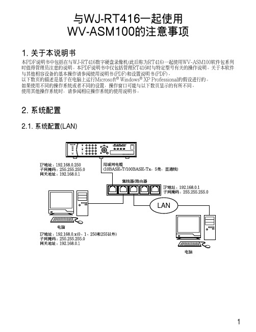
2. 系统配置2.1. 系统配置(LAN)12.2. 系统配置(WAN)3. 关于电脑环境3.1. 使用多监视器系统在有多监视器系统的电脑上使用本软件时,在首选监视器以外的监视器上显示实时图像时可能会显示黑色噪声。
建议使用本软件时不要使用多监视器系统3.2. 使用屏幕保护如果在显示实时图像时启动3维屏幕保护,本软件会因出错意外关闭。
建议使用本软件时不要使用3维屏幕保护。
4. 实时图像显示/回放4.1. 在显示实时图像时每RT416可以显示最多来自16台摄像机的实时图像。
*显示来自5台以上摄像机的实时图像时,来自所有摄像机的实时图像都将按照RT416设置的刷新间隔刷新实时图像。
关于如何配置刷新间隔请参阅RT416上的摄像机的使用说明书。
4.2. 实时图像显示的图像性能不能在16画面上同时显示来自4个以上RT416的实时图像。
如果试图这样做,实时图像的刷新间隔会变慢或者软件操作变得沉重。
建议在9画面上显示来自4个以上RT416的实时图像。
24.3. 回放图像时每RT416可以回放最多来自4台摄像机的记录图像。
每RT416仅允许单一用户回放记录图像。
注:•开始回放时,其他用户所监视的实时图像将会按照RT416设置的刷新间隔刷新。
NVIDIA Nsight Systems 2022.3.4安装指南说明书

Nsight Systems Installation GuideTABLE OF CONTENTS Chapter 1. Overview (1)Chapter 2. System Requirements (3)Supported Platforms (3)CUDA Version (3)Requirements for x86_64, Power, and Arm SBSA T argets on Linux (4)x86_64 Windows T arget Device Requirements (5)Host Application Requirements (5)Chapter 3. Getting Started Guide (7)3.1. Finding the Right Package (7)3.2. Installing GUI on the Host System (8)3.3. Optional: Setting up the CLI (8)3.4. Launching the GUI (9)Nsight Systems is a statistical sampling profiler with tracing features. It is designed to work with devices and devkits based on NVIDIA Tegra SoCs (system-on-chip), Arm SBSA (server based system architecture) systems, IBM Power systems, and systems based on the x86_64 processor architecture that also include NVIDIA GPU(s). Throughout this document we will refer to the device on which profiling happens as the target, and the computer on which the user works and controls the profiling session as the host. Note that for x86_64 based systems these may be on the same device, whereas with Tegra, Arm, or IBM Power based systems they will always be separate. Furthermore, three different activities are distinguished as follows:‣Profiling — The process of collecting any performance data. A profiling session in Nsight Systems typically includes sampling and tracing.‣Sampling — The process of periodically stopping the profilee (the application under investigation during the profiling session), typically to collect backtraces (call stacks of active threads), which allows you to understand statistically how much time is spent in each function. Additionally, hardware counters can also be sampled. This process is inherently imprecise when a low number of samples have been collected.‣Tracing — The process of collecting precise information about various activities happening in the profilee or in the system. For example, profilee API execution may be traced providing the exact time and duration of a function call.Nsight Systems supports multiple generations of Tegra SoCs, NVIDIA discrete GPUs, and various CPU architectures, as well as various target and host operating systems. This documentation describes the full set of features available in any version of Nsight Systems. In the event that a feature is not available in all versions, that will be noted in the text. In general, Nsight Systems Embedded Platforms Edition indicates the package that supports Tegra processors for the embedded and automotive market and Nsight Systems Workstation Edition supports x86_64, IBM Power, and Arm server (SBSA) processors for the workstation and cluster market.Common features that are supported by Nsight Systems on most platforms include the following:‣Sampling of the profilee and collecting backtraces using multiple algorithms (such as frame pointers or DWARF data). Building top-down, bottom-up, and flat viewsOverviewas appropriate. This information helps identify performance bottlenecks in CPU-intensive code.‣Sampling or tracing system power behaviors, such as CPU frequency.‣(Only on Nsight Systems Embedded Platforms Edition)Sampling counters from Arm PMU (Performance Monitoring Unit). Information such as cache misses gets statistically correlated with function execution.‣Support for multiple windows. Users with multiple monitors can see multiple reports simultaneously, or have multiple views into the same report file.With Nsight Systems, a user could:‣Identify call paths that monopolize the CPU.‣Identify individual functions that monopolize the CPU (across different call paths).‣For Nsight Systems Embedded Platforms Edition, identify functions that have poor cache utilization.‣If platform supports CUDA, see visual representation of CUDA Runtime and Driver API calls, as well as CUDA GPU workload. Nsight Systems uses the CUDA Profiling Tools Interface (CUPTI), for more information, see: CUPTI documentation.‣If the user annotates with NVIDIA Tools Extension (NVTX), see visual representation of NVTX annotations: ranges, markers, and thread names.‣For Windows targets, see visual representation of D3D12: which API calls are being made on the CPU, graphic frames, stutter analysis, as well as GPU workloads(command lists and debug ranges).‣For x86_64 targets, see visual representation of Vulkan: which API calls are being made on the CPU, graphic frames, stutter analysis, as well as Vulkan GPU workloads (command buffers and debug ranges).Nsight Systems supports multiple platforms. For simplicity, think of these as Nsight Systems Embedded Platforms Edition and Nsight Systems Workstation Edition, where Nsight Systems Workstation Edition supports desktops, workstations, and clusters with x86_64, IBM Power, and Arm SBSA CPUs on Linux and Windows OSs, while Nsight Systems Embedded Platforms Edition supports NVIDIA Tegra products for the embedded and gaming space on Linux for Tegra and QNX OSs.Supported PlatformsDepending on your OS, different GPUs are supportedL4T (Linux for Tegra)‣Jetson AGX Xavier‣Jetson TX2‣Jetson TX2i‣Jetson TX‣Jetson Nano‣Jetson Xavier NXx86_64, IBM Power (from Power 9), or Arm SBSA‣NVIDIA GPU architectures starting with Pascal‣OS (64 bit only)‣Ubuntu 18.04 and 20.04‣CentOS and RedHat Enterprise Linux 7.4+ with kernel version 3.10.0-693 or later.‣Windows 10, 11CUDA Version‣Nsight Systems supports CUDA 10.0, 10.1, 10.2, and 11.X for most platforms‣Nsight Systems on Arm SBSA supports 10.2 and 11.X Note that CUDA version and driver version must be compatible.CUDA Version Driver minimum version11.045010.2440.3010.1418.3910.0410.48From CUDA 11.X on, any driver from 450 on will be supported, although new features introduced in more recent drivers will not be available.For information about which drivers were specifically released with each toolkit, see CUDA Toolkit Release Notes - Major Component VersionsRequirements for x86_64, Power, and Arm SBSAT argets on LinuxWhen attaching to x86_64, Power, or Arm SBSA Linux-based target from the GUI on the host, the connection is established through SSH.Use of Linux Perf: To collect thread scheduling data and IP (instruction pointer) samples, the Linux operating system's perf_event_paranoid level must be 2 or less. Use the following command to check:If the output is >2, then do the following to temporarily adjust the paranoid level (note that this has to be done after each reboot):To make the change permanent, use the following command:Kernel version: To collect thread scheduling data and IP (instruction pointer) samples and backtraces, the kernel version must be:‣ 3.10.0-693 or later for CentOS and RedHat Enterprise Linux 7.4+‣ 4.3 or greater for all other distros including UbuntuTo check the version number of the kernel on a target device, run the following command on the device:Note that only CentOS, RedHat, and Ubuntu distros are tested/confirmed to work correctly.glibc version: To check the glibc version on a target device, run the following command:Nsight Systems requires glibc 2.17 or more recent.CUDA: See above for supported CUDA versions in this release. Use the deviceQuery command to determine the CUDA driver and runtime versions on the system. the deviceQuery command is available in the CUDA SDK. It is normally installed at:Only pure 64-bit environments are supported. In other words, 32-bit systems or 32-bit processes running within a 64-bit environment are not supported.Nsight Systems requires write permission to the /var/lock directory on the target system.Docker: See Collecting Data within a Docker section of the User Guide for more information.x86_64 Windows T arget Device RequirementsDX12 Requires:‣Windows 10 with NVIDIA Driver 411.63 or higher for DX12 trace‣Windows 10 April 2018 Update (version 1803, AKA Redstone 4) with NVIDIA Driver 411.63 or higher for DirectX Ray Tracing, and tracing DX12 Copy command queues.Host Application RequirementsThe Nsight Systems host application runs on the following host platforms:‣Windows 10, Windows Server 2019. Only 64-bit versions are supported.‣Linux Ubuntu 14.04 and higher are known to work, running on other modern distributions should be possible as well. Only 64-bit versions are supported.‣OS X 10.10 "Yosemite" and higher.3.1. Finding the Right PackageNsight Systems is available for multiple targets and multiple host OSs. To choose the right package, first consider the target system to be analyzed.‣For Tegra target systems, select Nsight Systems for Tegra available as part of NVIDIA JetPack SDK.‣For x86_64, IBM Power target systems, or Arm SBSA select from the target packages from Nsight Systems for Workstations, available from https:/// nsight-systems. This web release will always contain the latest and greatest Nsight Systems features.‣The x86_64, IBM Power, and Arm SBSA target versions of Nsight Systems are also available in the CUDA Toolkit.Each package is limited to one architecture. For example, Tegra packages do not contain support for profiling x86 targets, and x86 packages do not contain support for profiling Tegra targets.After choosing an appropriate target version, select the package corresponding to the host OS, the OS on the system where results will be viewed. These packages are inthe form of common installer types: .msi for Windows; .run, .rpm, and .deb for x86 Linux; .deb and .rpm for Linux on IBM Power; and .dmg for the macOS installer. Note: the IBM Power and Arm SBSA packages do not have a GUI for visualization of the result. If you wish to visualize your result, please download and install the GUI available for macOS, x86_64 Linux, or Windows systems.Tegra packages‣Windows host – Install .msi on Windows machine. Enables remote access to Tegra device for profiling.‣Linux host – Install .run on Linux system. Enables remote access to Tegra device for profiling.‣macOS host – Install .dmg on macOS machine. Enables remote access to Tegra device for profiling.Getting Started Guidex86_64 packages‣Windows host – Install .msi on Windows machine. Enables remote access to Linux x86_64 or Windows devices for profiling as well as running on local system.‣Linux host – Install .run, .rpm, or .deb on Linux system. Enables remote access to Linux x86_64 or Windows devices for profiling or running collection on localhost.‣Linux CLI only – The Linux CLI is shipped in all x86 packages, but if you just want the CLI, we have a package for that. Install .deb on Linux system. Enables only CLI collection, report can be imported or opened in x86_64 host.‣macOS host – Install .dmg on macOS machine. Enables remote access to Linux x86_64 device for profiling.IBM Power packages‣Power CLI only - The IBM Power support does not include a host GUI. Install .deb or .rpm on your Power system. Enables only CLI collection, report can be imported or opened in GUI on any supported host platform.Arm SBSA packages‣Arm SBSA CLI only - Arm SBSA support does not include a host GUI. Install .deb or .rpm on your Arm SBSA system. Enables only CLI collection, report can beimported or opened in GUI on any supported host platform.3.2. Installing GUI on the Host SystemCopy the appropriate file to your host system in a directory where you have write and execute permissions. Run the install file, accept the EULA, and Nsight Systems will install on your system.On Linux, there are special options to enable automated installation. Running the installer with the --accept flag will automatically accept the EULA, running withthe --accept flag and the --quiet flag will automatically accept the EULA without printing to stdout. Running with --quiet without --accept will display an error. The installation will create a Host directory for this host and a Target directory for each target this Nsight Systems package supports.All binaries needed to collect data on a target device will be installed on the target by the host on first connection to the device. There is no need to install the package on the target device.If installing from the CUDA Toolkit, see the CUDA Toolkit documentation.3.3. Optional: Setting up the CLIAll Nsight Systems targets can be profiled using the CLI. IBM Power and Arm SBSA targets can only be profiled using the CLI. The CLI is especially helpful when scripts are used to run unattended collections or when access to the target system via ssh is not possible. In particular, this can be used to enable collection in a Docker container.Getting Started Guide Installation Guide v2022.3.4 | 9The CLI can be found in the Target directory of the Nsight Systems installation. Users who want to install the CLI as a standalone tool can do so by copying the files within the Target directory to the location of their choice.If you wish to run the CLI without root (recommended mode) you will want to install in a directory where you have full access.Once you have the CLI set up, you can use the nsys status -e command to check your environment.~$ nsys status -e Sampling Environment Check Linux Kernel Paranoid Level = 1: OK Linux Distribution = Ubuntu Linux Kernel Version = 4.15.0-109-generic: OK Linux perf_event_open syscall available: OK Sampling trigger event available: OK Intel(c) Last Branch Record support: Available Sampling Environment: OKThis status check allows you to ensure that the system requirements for CPU sampling using Nsight Systems are met in your local environment. If the Sampling Environment is not OK, you will still be able to run various trace operations.Intel(c) Last Branch Record allows tools, including Nsight Systems to use hardware to quickly get limited stack information. Nsight Systems will use this method for stack resolution by default if available.For information about changing these environment settings, see System Requirements section in the Installation Guide. For information about changing the backtrace method,see Profiling from the CLI in the User Guide.To get started using the CLI, run nsys --help for a list of options or see Profiling Applications from the CLI in the User Guide for full documentation.3.4. Launching the GUIDepending on your OS, Nsight Systems will have installed an icon on your host desktop that you can use to launch the GUI. To launch the GUI directly, run the nsight-sys executable in the Host sub-directory of your installation.。
StarWind Virtual SAN 硬件无VM存储快速入门指南说明书

Quick Start Guide: Creating Stand-Alone Image File Device with StarWind Virtual SANtrADeMArKS“StarWind”, “StarWind Software” and the StarWind and the StarWind Software logos are trademarks of StarWind Software which may be registered in some jurisdictions. All other trademarks are owned by their respective owners.CHANGeSThe material in this document is for information only and is subject to change without notice. While reasonable efforts have been made in the preparation of this document to assure its accuracy, StarWind Software assumes no liability resulting from errors or omissions in this document, or from the use of the information contained herein. StarWind Software reserves the right to make changes in the product design without reservation and without notification to its users.teCHNICAL SUPPOrt AND SerVICeSIf you have questions about installing or using this software, check this and other documents first - you will find answers to most of your questions on the Technical Papers webpage or in StarWind Forum. If you need further assistance, please contact us. COPyrIGHt ©2009-2014 StArWIND SOFtWAre INC.No part of this publication may be reproduced, stored in a retrieval system, or transmitted in any form or by any means, electronic, mechanical, photocopying, recording or otherwise, without the prior written consent of StarWind Software.INtrODUCtIONStarWind Virtual SAN™ is a native Windows hypervisor-centric hardware-less VM storage solution. It allows creating VM-centric and high performing storage pool purpose built for the virtualization workloads. StarWind Virtual SAN delivers supreme performance compared to any dedicated SAN solution since it runs locally on the hypervisor and all IO is processed by local RAM, SSD cache, and disks and never bottlenecked by storage fabric. This guide is intended for experienced Windows system administrators and IT professionals who would like to configure StarWind Virtual SAN solution. It provides detailed instructions on how to create StarWind Basic Image File device that will run on top of the Windows Server 2012 R2.A full set of up-to-date technical documentation can always be found here, or by pressing the Help button in the StarWind Management Console.For any technical inquiries please visit our online community, Frequently Asked Questions page, or use the support form to contact our technical support department.1. Launch the S tarWind Management Console: double-click the StarWind tray icon. Please note: S tarWind Management Console cannot be installed on an operating system without a GUI. You can install it on any of the GUI-enabled Windows Editions including the desktop versions of Windows.If StarWind Service and Management Console are installed on the same server, the Management Console will automatically add the local StarWind instance to the Console tree after the first launch. Then, the Management Console automatically connects to it using the default credentials. To add remote StarWind servers to the console use the Add Server button on the control panel.2. StarWind Management console will ask you to specify the default storage pool on the server you’re connecting to for the first time. Please configure the storage pool to use the one of the volumes you’ve prepared earlier. All the devices created through the Add Device wizard will be stored on it.Press Yes button to configure the storage pool. Should you require to changethe storage pool destination, press Choose path… and point the browser to the necessary disk.Note: Each of the arrays which will be used by StarWind Virtual SAN to store virtual disk images has to meet the following requirements:• initialized as GPT• Have a single NTFS-formatted partition• Have a drive letter assigned3. Select the StarWind server where you wish to create the device.4. Press the Add Device (advanced) button on the toolbar.5. Add Device Wizard will appear. Select Hard disk device and click Next.6. Select Virtual disk and click Next.7. Specify the virtual disk location and size and click Next button.8. Specify virtual disk options and click Next button.9. Define the caching policy and specify the cache size (in MB).Note: we recommended to use 1Gb cache per 1Tb storage. Click Next button after the configuration of cache parameters is completed.Define the L2 caching policy and size if necessary. Note: We recommend to use SSD for L2 cache and if it will be used, the formula is 1Gb (sum of L1 and L2) cache per 1Tb storage. After completing this step press Next button.10. Specify the destination directory for the L2 cache, if any.11. Specify target parameters. Select the Target Name checkbox to enter a custom name ofa target. Otherwise, the name will be generated automatically based on the target alias. Click Next after completing this step.12. Click Create to add a new device and attach it to the target.13. Then click OK to close the wizard.Customer Support Portal:Support Forum:Sales: General Information:US HeadquartersPhone:Fax:EMEA and APACPhone:Voice Mail:/support /forums ***************************************************1-617-449-77171-617-507-5845+44-0-2071936727+44-0-2071936350+33-0-977197857 (French)1-866-790-2646StarWind Software Inc.301 Edgewater Place, Suite 100,Wakefield, MA 01880, USA CONtACtS。
亚信安全终端安全管控系统准入设备安装手册

亚信安全终端安全管控系统准入设备安装手册目录1、设备说明 (3)2、配置步骤 (3)3、测试环境资源需求 (3)4、端口镜像配置 (3)5、设备上架 (4)6、配置ETH3 ip地址 (4)7、接线 (5)8、服务端、管理端安装 (5)8.1、服务端安装 (5)8.2、管理端安装 (6)9、准入配置及调试 (7)10、测试 (8)11、异常检查 (9)准入控制设备为可选干路方式或者旁路方式对于网络接入控制的硬件设备。
2、配置步骤准入设备配置分为一下几个过程:1、镜像配置2、设备上架、3、配置ETH3地址4、确认数据、5、设置界面3、测试环境资源需求服务器:测试服务器装服务端软件,windows server2008/2003系统,4g内存,200g 硬盘交换机:(核心或者非核心)支持端口镜像交换机,将上行口镜像到准入口,准入设备接到准入口上ip分配以及网络连通性:服务器需要1个ip,准入设备需要1个ip,以上ip互相连同终端pc:window系统真实机,不要虚拟机。
4、端口镜像配置与用户前期沟通时,告知对方,设备推荐采用旁路方式接入网络,需要用户配合配置端口镜像,了解对方网络是外包维护还是自己维护的,如果外包维护,需要告知对方测试时候将维护公司技术人员一起到场,配置端口镜像。
设备为1U设备,与用户确定好上架位置,将设备上架,包装箱中有相关的配件。
6、配置ETH3 ip地址用网线直连笔记本和准入设备ETH2口,把笔记本电脑设置IP :3.3.3.8 子网掩码255.0.0.0在浏览器地址中输入3.3.3.3 ,登录用户名admin密码admin,进行设置ETH3口IP,输入对应的IP(192.168.1.252)、子网掩码、网关。
确定保存,准入设备自动重启。
7、接线交换机的镜像口接线到准入设备ETH1,组端口接线到交换上。
8、服务端、管理端安装8.1、服务端安装在服务器上安装服务端,服务端安装参考软件使用手册。
深信服服务器虚拟化asv操作步骤

服务器虚拟化操作步骤1环境确认服务器虚拟化的目的在于将客户现有运行在物理主机上的业务系统平滑地转移到VMP 虚拟机中运行。
实施服务器虚拟化操作前,需要确认以下必要条件,条件不满足时,会导致操作失败。
同时建议在操作前先对服务器进行重启,确认服务器重启后能正常运行。
2服务器虚拟化2.1迁移物理主机迁移物理主机,可以将现有物理主机上的Windows/Linux操作系统通过网络克隆到SANGFOR VMP平台上。
迁移过程中会重启原主机,迁移完成后原操作系统可以在VMP平台上继续运行。
原主机上的操作系统恢复原状,不做任何修改,可以关机,也可以开机继续使用。
2.1.1Windows迁移Windows操作系统下的迁移工具是名为Sangfor_aSV_Converter的exe可执行程序(已集成到VMP安装光盘中),直接在Windows操作系统下运行后,界面如下图所示。
先勾选“已阅读许可协议”,然后点击“迁移物理主机”的“立即安装”按钮。
安装前该工具会获取当前物理主机的相关信息,检查安装环境是否满足必要条件。
如果条件不满足,会以红色警告信息进行提示,需要更正后重新运行该软件。
安装条件检查通过后,需要先配置迁移到目标VMP平台的连接。
该工具会自动发现当前网段中的VMP控制器,只需要提供该VMP的管理员帐号密码即可成功连接。
如果没有自动发现,可以手动输入其IP进行添加。
连接目标VMP成功后,迁移工具会将当前Windows操作系统克隆到目标VMP平台上,作为一个虚拟机来运行。
所以还需要配置该虚拟机在VMP平台上的相关信息,包括虚拟机名称、存储和运行位置、硬件配置等。
配置完成后会将当前配置信息进行确认,确认无误后即可进行安装。
安装过程只会在Windows系统的C盘安装迁移程序,不会修改当前操作系统的配置。
安装完成后需要重启Windows操作系统,重启后开始迁移。
此时可以选择迁移完成后是否开启原主机或虚拟机。
注意:由于迁移完成后的虚拟机和原主机内容一模一样,包括IP等配置也一样。
APV 安装手册(阿里云平台)说明书

vAPV安装手册(阿里云平台)版权声明版权声明本文档受版权保护,未经Array Networks许可,任何人不得以任何理由和形式使用、复制、传播和编辑本文档,除非是在版权法的许可范围内。
本手册所涉及的案例均是当前情况,Array Networks有权利随时更改,恕不提前通知。
对于本手册内容,包括但不限于隐含的商业性能和特定用途适应性说明,Array Networks不承担任何责任。
Array Networks对于因本手册的提供造成的设备性能、使用和按键错误而导致的相关事故或因之引起的损害不承担任何责任。
警告:未经Array Networks许可,任何人不得对Array APV设备进行任何改动,否则将无权继续使用该设备。
商标声明本手册中所涉及的产品名称仅作识别之用。
手册中涉及的其他公司的注册商标或版权属各商标注册人所有,恕不逐一列明。
合格声明Array Networks自主声明Array APV系列产品符合FCC规定第15条。
操作本设备需要满足下面条件:(1)本设备不会产生有害干扰,(2)本设备不屏蔽任何干扰,其中有些干扰可能会造成不良影响。
警告:Array APV系列设备属于FCC(美国联邦通讯委员会)规定第十五条定义的A 类数据设备。
该条例旨在合理保护关于设备的商业行为,以避免生产生活环境受到不良影响。
本设备会产生、使用并且放射无线电磁波,如果不按照用法说明来使用,将有可能对无线电通讯产生影响。
在居住区和家庭中使用本设备有可能造成有害影响,为此使用者可能需要采取一定保护措施。
关于Array Networks 联系Array Networks请通过以下方式联系Array Networks:网站:/电话:总机(付费):(408)240-8700总机(免费):1-866-692-7729 (1-866-MY-ARRAY)技术支持:1-877-992-7729 (1-877-99-ARRAY)传真:(408)240-8754电话联系时间:周一至周五早9点至晚5点(太平洋标准时间)电子邮箱:**********************地址:1371 McCarthy BoulevardMilpitas, California 95035, USA修订记录修订记录日期描述2016-05-27 首次发布。
无线ap管理
技术支持说明
为了让您在安装,调试、配置、维护和学习 SUNDRAY 设备时,能及时、快速、有效 的获得技术支持服务,我们建议您: 1.参考本快速安装手册图文指导,帮助你快速的完成部署、安装 SUNDRAY 设备。如果快速安 装手册不能满足您的需要, 您可以到 SUNDRAY 技术论坛或官网获得电子版的完整版用户手册 或者其他技术资料,以便您获得更详尽的信息。 2.致电您的产品销售商(合同签约商) ,寻求技术支持。为了更快速响应您的服务要求并保 证服务质量, 您所在地 SUNDRAY 的产品销售商配备有经过厂家认证的技术工程师, 会向您提 供快捷的电话咨询、远程调试及必要的上门调试服务。 3.在非紧急情况下,您可以访问 SUNDRAY 技术论坛,寻求技术问题的解决方案和办法。 4.致电 SUNDRAY 客服中心, 确认最适合您的服务方式和服务提供方, 客服中心会在您的技术 问题得到解决后, 帮助您获得有效的服务信息和服务途径, 以便您在后续的产品使用和维护 中最有效的享受技术支持服务,及时、有效的解决产品使用中的问题。 公司网址: 技术支持服务热线: 4008783389(手机、固话均可拨打) 邮箱:support@
iv SUNDRAY WNS v3.0 Quick
声明
Copyright © 2015 深圳市信锐网科技术有限公司及其许可者版权所有,保留一切权利。 未经本公司书面许可,任何单位和个人不得擅自摘抄、复制本书内容的部分或全部,并 不得以任何形式传播。 SUNDRAY 为深圳市信锐网科技术有限公司的商标。对于本手册出现的其他公司的商 标、产品标识和商品名称,由各自权利人拥有。 除非另有约定,本手册仅作为使用指导,本手册中的所有陈述、信息和建议不构成任何 明示或暗示的担保。 本手册内容如发生更改,恕不另行通知。 如需要获取最新手册,请联系信锐网科技术有限公司客户服务部。
Sophos XG Firewall Virtual Appliance 部署指南说明书
ContentsIntroduction (1)Installation procedure (2)Configuring XG Firewall (4)Activation and Registration (4)Basic Configuration (4)Legal notices (8)Sophos XG Firewall Virtual Appliance1 IntroductionWelcome to the Getting Started guide for Sophos XG Firewall Virtual Appliance (referred to in this document as “XG Firewall”) for VMware ESX/ESXi platform. This guide describes how you can download, deploy and run XG Firewall as a virtual machine on VMware ESX/ESXi.Minimum hardware requirement1.One vCPU2.2GB vRAM3. 2 vNIC4.Primary Disk with a minimum of 4 GB space5.Report Disk with a minimum of 80 GB spaceNoteSFOS 17 supports hard drives with a maximum of 512 GB.XG Firewall will go into fail-safe mode if the minimum requirements are not met.NoteTo optimize the performance of your XG Firewall, configure vCPU and vRAM according to the license you have purchased. When configuring a number of vCPUs, make sure that you do not exceed the maximum number specified in your license.Sophos XG Firewall Virtual Appliance2 Installation procedureMake sure that VMware ESX/ESXi version 5.0 or later is installed in your network. For VMware ESX/ ESXi installation instructions, refer to the VMware documentation /support/ pubs/vsphere-esxi-vcenter-server-pubs.html.You need to:1.Download and extract the OVF image2.Access the ESX/ESXi Host via vSphere Client3.Deploy the OVF Template4.Power on1.Download the .zip file containing the OVF image from https://secure/en-us/products/next-gen-firewall/free-trial.aspx and save it.2.Log in to the ESX/ESXi host server on which you want to deploy the OVF template throughVMware vSphere Client.NoteIn this guide, we are using VMware vSphere client to connect to the ESX/ESXi host server onwhich the OVF template is to be deployed.a)Go to File > Deploy OVF Template to open the downloaded .ovf file in the vSphere Client.b)Select the sf_virtual file and click Open.3.To deploy the OVF template:a)Select the location of the .ovf file for XG Firewall and click Next to continue.Sophos XG Firewall Virtual Applianceb)Verify the OVF template details and click Next to continue.c)Specify a name and location for the OVF template to be deployed and click Next to continue.d)Select the host/cluster within which you want to deploy the OVF template and click Next tocontinue.NoteHere, we are deploying the OVF template on a single/standalone server. The configurationmay be different in a cluster environment.e)Select the format in which you want to store the virtual disks from the available options:Thin Provision: It uses the minimum required space for the OVF template, saving the restfor other use.Thick Provision: It uses the entire allotted virtual disk for OVF template installation, wipingout additional data on the disk.In case of VMware ESXi 5.0 or later, three storage options are available: Thin Provision,Thick Provision Lazy Zeroed and Thick Provision Eager Zeroed. For more information,refer to /.f)Click Next to continue.g)Select the networks to be used by the OVF template and click Next to continue.h)Verify the deployment settings for the OVF Template and click Finish to initiate the deploymentprocess of XG Firewall.This installs XG Firewall on your machine.4.Right-click the deployed XG Firewall and go to Power > Power On.a)Enter the administrator password: ‘admin’ to continue to the Main Menu.Sophos XG Firewall Virtual Appliance3 Configuring XG Firewall1.Browse to "https://172.16.16.16" from the management computer.2.Click Start to begin the wizard and follow the on-screen instructions.NoteThe wizard will not start if you have changed the default administrator password from theconsole.3.1 Activation and Registration1.Review and accept the License Agreement. You must accept the Sophos End User LicenseAgreement (EULA) to proceed further.2.Register Your Firewall. Enter the serial number, if you have it. You can also use your UTM 9license if you are migrating.Otherwise, you can skip registration for 30 days or start a free trial.a)You will be redirected to the MySophos portal website. If you already have a MySophosaccount, specify your sign-in credentials under “Login”. If you are a new user, sign up for aMySophos account by filling in the details under “Create Sophos ID”.b)Complete the registration process.Post successful registration of the device, the license is synchronized and the basic setup is done.3.Finish the basic setup. Click Continue and complete the configurations through the wizard. Whenyou finish the process, the Network Security Control Center appears.You can now use the navigation pane to the left to navigate and configure further settings.3.2 Basic ConfigurationYou can:1.Set up Interfaces2.Create Zones3.Create Firewall Rules4.Set up a Wireless Network1.To set up interfaces:a)You can add network interfaces and RED connections in the Configure > Network >Interfaces menu.b)You can add wireless networks in the Protect > Wireless > Wireless Networks menu.SSIDs will also be shown in the interfaces menu once created.c)You can add access points in Protect > Wireless > Access Points.Sophos XG Firewall Virtual ApplianceSophos XG Firewall Virtual ApplianceYou can see both these wireless networks in Protect > Network > Wireless Networks.e)Go to Protect > Wireless > Access Point Groups.f)Click Add to add a new access point group.g)Add both the wireless networks, and the new access point.If new APs have been installed, you can view these in Control Center.h)Click the pending APs to accept the new access points.i)Configure the settings of the new APs as shown in the image.Sophos XG Firewall Virtual Appliancej)Click Save.Sophos XG Firewall Virtual Appliance4 Legal noticesCopyright © 2020 Sophos Limited. All rights reserved. No part of this publication may be reproduced, stored in a retrieval system, or transmitted, in any form or by any means, electronic, mechanical, photocopying, recording or otherwise unless you are either a valid licensee where the documentation can be reproduced in accordance with the license terms or you otherwise have the prior permission in writing of the copyright owner.Sophos, Sophos Anti-Virus and SafeGuard are registered trademarks of Sophos Limited, Sophos Group and Utimaco Safeware AG, as applicable. All other product and company names mentioned are trademarks or registered trademarks of their respective owners.Copyright © 2020 Sophos Limited. All rights reserved. No part of this publication may be reproduced, stored in a retrieval system, or transmitted, in any form or by any means, electronic, mechanical, photocopying, recording or otherwise unless you are either a valid licensee where the documentation can be reproduced in accordance with the license terms or you otherwise have the prior permission in writing of the copyright owner.Sophos and Sophos Anti-Virus are registered trademarks of Sophos Limited and Sophos Group.All other product and company names mentioned are trademarks or registered trademarks of their respective owners.。
- 1、下载文档前请自行甄别文档内容的完整性,平台不提供额外的编辑、内容补充、找答案等附加服务。
- 2、"仅部分预览"的文档,不可在线预览部分如存在完整性等问题,可反馈申请退款(可完整预览的文档不适用该条件!)。
- 3、如文档侵犯您的权益,请联系客服反馈,我们会尽快为您处理(人工客服工作时间:9:00-18:30)。
aSV软件安装和初始化配置指导书1.1.aSV安装说明
1.1.1.最低硬件要求
CPU:支持x64与Intel® Virtualization Technology (VT-x)
内存:4GB
硬盘:60GB
主板:开启VT(VT-x)功能
1.1.
2.BIOS开启VT(VT-x)功能
在bios里开启vt技术支持,实例如下(注意每款主板不一样,大同小异)
1.1.3.U盘烧录ASV安装镜像
所需使用的软件:UltraISO
制作过程:首先插入U盘,然后按下面的步骤做1)打开软件UltraISO
2)加载vtp的iso,然后选择需要刻盘的iso文件。
3)加载iso之后如下所示(文件名以当前下载镜像名为准,此处仅为参考)
4)然后点击启动---写入硬盘映像
5)然后点击“写入”,其他默认就行了。
完成后返回把U盘拔出即可。
注意:
1)U盘写入格式使用USB-HDD或USB-HDD+都可以,推荐勾上刻录完成后校验。
1.1.4.安装ASV
1)服务器光驱插入ASV安装光盘,启动设备,BIOS设置光驱启动为第一优先级,重启设
备(设备内存需要大于4GB,才允许安装);系统进入启动界面,按【ENTER】键,进入安装界面;
2)点击【OK】,会检测当前CPU是否为Intel架构(如果CPU为AMD架构,会提示CPU
类型不支持,退出安装);
3)选择安装所在磁盘,如果只有一块硬盘,直接点击【OK】(所选硬盘容量需要大于60GB
才允许安装);
4)选择磁盘后提示需要格式化硬盘数据,请点击【YES】,如果硬盘数据需要保留,请选择
【NO】回退到硬盘选择界面;硬盘满足大于40GB容量的检查后,开始安装;
5)系统安装完成后,提示是否设置网络,选择【YES】进入网卡设置界面,选择【NO】则
安装完成,所选网卡会自动赋予一个默认IP,eg:eth0默认IP为192.168.0.7;eth1默认IP为192.168.1.7;
6)选择需要配置的网卡,点击【OK】;
7)设置网卡IP、子网掩码、网关,点击【Continue】;
8)单张网卡设置好后,提示是否继续设置其他网卡,点击【YES】,返回网卡选择界面;点
击【NO】则安装完成;
9)安装完成后,点击【Reboot】,重启设备,安装完毕;
1.2.ASV使用说明
1.2.1.控制台
1)根据配置的网卡IP,登录ASV控制台,默认账户密码:admin;
2)控制台顶层区域为ASV功能栏,主要包括
[首页]:显示系统概况、包括实体机和存储状态,主机和虚拟机总数,CPU、内存和存储使用率等,操作包括虚拟机、物理主机和存储添加等操作。
[虚拟机]:虚拟机页面分组显示所有虚拟机,提供虚拟机及分组管理功能。
[虚拟网络]:用于虚拟交换机及其关联关系的管理编辑。
[实体机]:包括物理主机和存储。
可以添加和管理主机及存储。
[管理]:配置序列号、系统时间、全局快照、告警、配置备份恢复和升级等。
注意:建议屏幕分辨率在1280*720以上
页面右下角的浮动窗口显示当前正在执行的任务数量,点击可以查看详细的任务执行过程和结果。
1.2.2.实体机
实体机是相对虚拟机的概念,包括物理主机和物理存储。
1.2.2.1.物理主机
物理主机是指安装了ASV软件的物理主机,可以统一把这些物理主机加入到同一个管理平台进行维护,方便业务部署,也可以提高资源的有效利用率。
物理主机包括(1)全新安装:使用ISO镜像引导并全新安装的aSV主机,见1.1节说明,或者(2)快速虚拟化P2V:在现有物理主机的Windows操作系统上,通过安装虚拟化软件,对物理主机进行虚拟化成为aSV主机。
(快虚请参考“aSV快速部署手册-快虚安装-V3.0.docx”)
1.2.2.1.1.添加物理主机
添加已经安装了ASV操作系统或虚拟软件的物理主机,注意添加的IP是aSV主机的管
理IP,不是Windows操作系统的IP,账号密码默认均为admin。
添加完成后,该主机即作为当前aSV集群平台的一台物理主机使用。
1.2.2.2.存储
1)【存储】支持维护本地存储、ISCSI、FC等3种类型存储
存储用于虚拟机的磁盘数据保存,供VDC关联配置个人磁盘数据保存等。
2)[存储]页面展示的是当前已经发现本地磁盘、ISCSI磁盘和FC磁盘
[ISCSI服务器连接配置]:用于新增、编辑、删除ISCSI服务器
a、本地磁盘属于设备自带的硬盘,可以自动识别。
b、ISCSI磁盘通过[添加ISCSI服务器]设置,添加ISCSI服务器发现磁盘,如果服务器配置了CHAP认证,则添加时需要输入匹配的CHAP认证账户密码
C、与ASV直连的FC磁盘,可以被自动发现。
3)在存储页面上点击[更多],可以选择[详情状态]、[删除]、[格式化]等操作。
[删除]即将磁盘从ASV集群中移除。
本地磁盘不能被删除。
[格式化]新添加的磁盘需要格式化才能使用。
[详情状态]点击以查看该磁盘的详细数据。
包括[存储信息]显示当前磁盘的运行数据,[虚拟机]显示当前存储在该磁盘上的虚拟机,[连接的主机]显示当前能使用该磁盘的ASV主机。
注意:ISCSI和FC属于共享存储,只有添加了共享存储,虚拟机才能进行自动故障迁移。
1.2.3.虚拟机的新建及安装
1.2.3.1.新增分组
分组等同于文件夹的概念,用于根据管理需求,将相同用途的虚拟机放到同一个目录下。
1.2.3.2.新增虚拟机并安装操作系统
新增虚拟机时,需要指定虚拟机名称,存储位置、运行位置和操作系统类型。
以新建一台windows2003为例。
1)点击【新增】,添加一台虚拟机:
置、选择需要安装的操作系统、选择分配给虚拟机的硬件参数。
如下图:
上传windows的iso进行文件,并给对应的虚拟机进行加载。
如下图:
4)安装虚拟机。
启动新建的这台虚拟机,从ASV控制台打开虚拟机并进行安装,如下图:
注意:如果是集群环境,虚拟机的存储位置是共享存储,则该虚拟机可以在运行主机出现故障时,自动切换到其他主机上运行。
1.2.4.操作和编辑虚拟机
点击虚拟机图标时,会看到当前虚拟机的运行状态和配置信息。
虚拟机可使用的操作命令有:
打开控制台:打开控制台进去虚拟机操作系统进行安装系统和软件等操作。
开机/关机/挂起:向虚拟机操作系统发送开关机等指令。
立即备份:虚拟机备份操作。
编辑:修改虚拟机的硬件信息。
可以调整CPU核数、内存大小、挂载硬盘等等,如下图(修改内存大小):
关闭/重启电源:电源管理。
克隆/迁移:虚拟机克隆和迁移操作。
部署虚拟机:以当前虚拟机为模版,派生虚拟机。
更新虚拟机:更新虚拟机的当前状态到所派生的虚拟机中。
1.2.5.虚拟机派生
1)模版部署
以一台虚拟机为模版,可以快速新建出若干相同的虚拟机。
点击“以此为模版部署虚拟机”,进行虚拟机派生部署。
部署虚拟机时,需要指定派生虚拟机的数量,存储位置、运行位置。
同时可以为新派生的虚拟机新增个人磁盘,修改派生虚拟机的硬件信息等。
2)更新虚拟机
管理员在模版中新安装了软件,需要更新到已经派生的虚拟机。
点击“更新以此为模版部署的虚拟机”,选择更新内容和更新时间。
1.2.6.虚拟机备份
虚拟机的备份,用于主机故障或虚拟机操作系统故障时,快速恢复到备份前的状态。
点击“立即备份”,可以备份虚拟机的当前状态。
如果备份位置为当前存储位置,则备份操作为快照,如果备份到其他存储位置,则备份操作为异地备份。
备份位置可以额外添加Windows共享存储。
除了单独对某台虚拟机进行手动备份,也可以添加自动备份策略,在指定时间对指定的虚拟机进行自动备份到某个位置。