德国易福门(IFM)电子样本--701163es
易福门 IFM LMT121
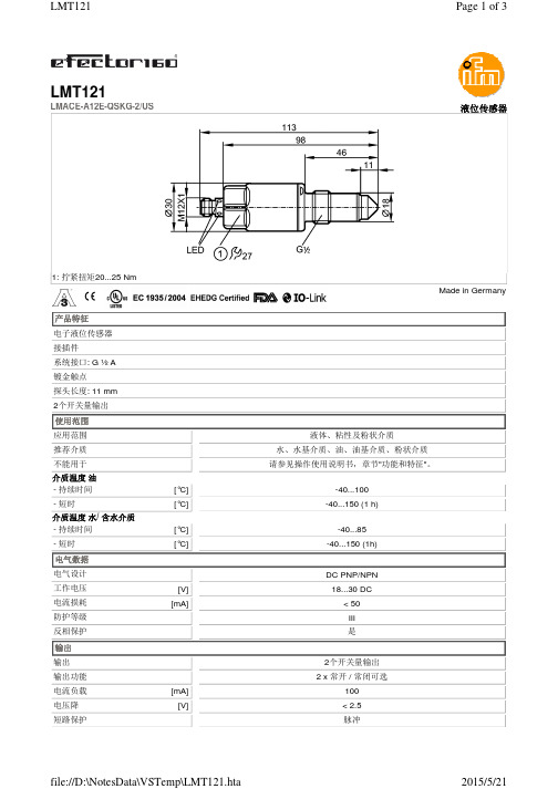
[°C][°C][°C][°C][V][mA][mA][V]LMT121LMACE-A12E-QSKG-2/US液位传感器1: 拧紧扭矩20...25 Nm特征电子液位传感器接插件系统接口: G ½ A 镀金触点探头长度: 11 mm 2个开关量输出使用范围应用范围液体、粘性及粉状介质推荐介质水、水基介质、油、油基介质、粉状介质不能用于请参见操作使用说明书,章节"功能和特征"。
介质温度 油- 持续时间-40...100- 短时-40...150 (1 h)介质温度 水/ 含水介质- 持续时间-40...85- 短时-40...150 (1h)电气数据电气设计DC PNP/NPN 工作电压18...30 DC 电流损耗< 50防护等级III 反相保护是输出输出2个开关量输出输出功能 2 x 常开 / 常闭可选电流负载100电压降< 2.5短路保护脉冲[ms][°C][°C][bar][年][kg][件]过载保护是接口IO-Link Device传递类型COM2 (38.4 kBaud)IO-Link revision 1.1SDCI标准根据IEC 61131-9 CDV标准IO-Link Device ID306 d / 00 01 32 h外形无轮廓SIO模式是必需的mater port type A模拟过程数据1二位输出过程数据2处理周期最小值 2.3环境条件环境温度-40 (60)存储温度-40 (80)最大的容器压力-1 (40)外壳防护等级IP 68 / IP 69K认证/测试EMC电磁兼容IEC 61000-6-2 : 2005IEC 61000-6-4 : 2006 / (敞开的存储罐)IEC 61000-6-3 : 2006 / (封闭的存储罐)抗冲击IEC 60068-2-27:50 g (11 ms)抗震DIN EN 60068-2-6:20 g (10...2000 Hz) MTTF223UL认证编号H001机械技术数据系统接口G ½ A材料(潮湿部件)PEEK; 表面特性: Ra < 0.8外壳材料 1.4404; PEEK; PEI; FKM重量0.195显示器/操作件显示开关状态 2 LED 黄色操作状态 2 LED 绿色电气连接接口M12接插件; 镀金触点接线注释包装单位1易福门电子(上海)有限公司 • 上海浦东新区 • 张江张衡路1000弄15号 • 邮编: 201203Phone 0086-21-3813 4800 • Fax 0086-21-5027 8669 • 400 National Service Hotline: 400 880 6651 — 我们保留不提前通知而变更技术参数的权利。
德国易福门(IFM)电子样本--701164es
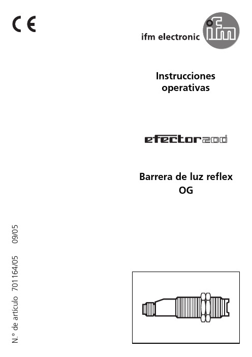
Ajuste de la sensibilidad para objetos en reposo
Conectar el aparato en modo Programación.
1
Presione la tecla durante unos 2 s, hasta que comience a parpadear el LED rojo. Se apaga el LED rojo; los LED amarillo y verde parpadean de forma alternativa. El aparato se encuentra en modo Programación. Ajustar la sensibilidad con el objeto.
Durante la medición (aprox. 1 s), deje que pasen al menos dos objetos por el campo de detección del sistema óptico.
2
Apriete la tecla 1 vez. Se apagan los LED amarillo y verde durante 1 s aprox.; a continuación, parpadean de manera alternativa. Durante la medición (aprox. 1 s), deje que pasen al menos dos objetos por el campo de detección del sistema óptico.
Conexión eléctrica
Para cumplir con los requisitos "limited Voltage" conforme a UL 508, debe alimentarse el aparato desde una fuente separada galvánicamente, asegurándolo con un dispositivo contra sobrecorriente. Desconecte el equipo de toda tensión. Proceda a conectar el aparato (v. página 17 o placa de características). Color de los hilos en los aparatos con cables: BN = marrón, BU = azul, BK = negro. Programación de la función de salida con la ocupación de las conexiones (v. página 17 o placa de características). Carga de la salida de control de la función (fc-output): 10 mA como máximo
德国IFM易福门液位传感器LMC100型选购指南及应用
德国IFM易福门液位传感器LMC100型选购指南及应用德国IFM易福门液位传感器LMC100型选购指南及应用德国IFM易福门液位传感器LMC100型是根据阿基米德浮力原理设计的。
浮筒式液位变送器是利用微小的金属膜应变传感技术来测量液体的液位、界位或密度的,它在工作时可以通过现场按键来进行常规的设定操作。
浮球式液位变送器由磁性浮球、测量导管、信号单元、电子单元、接线盒及安装件组成,一般磁性浮球的比重小于0.5,可漂于液面之上并沿测量导管上下移动,导管内装有测量元件,它可以在外磁作用下将被测液位信号转换成正比于液位变化的电阻信号,并将电子单元转换成4~20mA或其它标准信号输出。
液位传感器为模块电路,具有耐酸、防潮、防震、防腐蚀等优点,液位开关是根据液位传感器的信号输出开启放水或者进水的阀门而使水位保持恒定的一种控制器。
也可以说液位开关输出的是一种开关信号,液位开关首先要确定液位的高度,依据这个高度来输出开关量信号。
而液位传感器是将液位的高度转化为电信号的形式进行输出。
我们可以对电信号进行处理比如和plc、数据采集器或者专业显示器相连进而输出液位的高度。
还有就是液位开关和液位传感器的原理虽然相同。
但是液位开关是开关控制电路,而液位传感器是相当于变压,变流用的电路元件电路内部含有恒流反馈电路和内保护电路,可使输出最大电流不超过28mA因而能够可靠地保护电源并使二次仪表不被损坏静压投入式液位变送器(液位计)适用于石油化工、冶金、电力、制药、供排水、环保等系统和行业的各种介质的液位测量。
精巧的结构,简单的调校和灵活的安装方式为用户轻松地使用提供了方便。
4~20mA、 0~5v、 0~10mA等标准信号输出方式由用户根据需要任选。
利用流体静力学原理测量液位,是压力传感器的一项重要应用。
采用特种的中间带有通气导管的电缆及专门的密封技术,既保证了传感器的水密性,又使得参考压力腔与环境压力相通,从而保证了测量的高精度和高稳定性技术参数:特殊的性能镀金触点介质水; 水为基本的介质; 油; 油基介质; 冷却润滑剂; 粉末介质温度[°C]-25 (100)探杆长度 [mm]28储存罐压力[bar]-1 (40)电气设计 PNP/NPN输出功能常开/常闭; (可设定参数)短路保护有过载保护有短路保护类型热量,脉冲式。
ifm efector 电子压力传感器 PM-010-REA01-E-ZVG US 产品说明说明书

PM1704
Electronic pressure sensor
PM-010-REA01-E-ZVG/US
2-wire Current consumption Power-on delay time
[mA] [s]
3.5...21.5 1
3-wire Current consumption Power-on delay time
PM1704
Electronic pressure sensor
PM-010-REA01-E-ZVG/US
Interfaces
Communication interface
Transmission type
IO-Link revision
IO-Link d
-1...10 bar
-14.5...145 psi
-100...1000 kPa
-0.1...1 MPa
threaded connection G 1 external thread Aseptoflex Vario
gold-plated contacts
ceramic-capacitive pressure measuring cell
[mA] [Ω]
Measuring/setting range Measuring range Analog start point Analog end point In steps of Factory setting
Accuracy / deviations
Repeatability
[% of the span]
[mA] [s]
Inputs / outputs Number of inputs and outputs
德国易福门IFM电容式传感器型号

德国易福门IFM电容式传感器型号德国易福门IFM电容式传感器型号我司长期销售德国进口易福门IFM产品,原装,货期短,德国空运回国,购买贺德克产品请认准“上海维特锐“德国易福门IFM电容式传感器还可与控制室中的二次仪表或控制器相连,在线、连续、实时的检测各种低水分油品的含水率。
直接显示,远程控制和报警。
实现数据存储,积算、传输和控制功能。
普遍应用于大中型机械联动机组的液压、润滑循环系统例如:高线轧机和板带轧机润滑油系统、板带轧机和棒线轧机液压传动系统、汽轮发电机组润滑系统、造纸机组润滑系统、船舶机械润滑系统、燃料油库。
粘度计,污染度,湿度计电容式传感器IFM电容式传感器的原理:其在结构上有如下特点,这无论对使用和设汁制造上都必须充分注意才能保证发挥IFM电容传感器的长处。
①对绝缘要求高,因此极板支持构件或极板间绝缘材料均要求用有良好绝缘性能的如石英、陶瓷、聚四氟乙烯、云母等。
这是因为传感器电容一般不大(pf级),因此是高阻抗,绝缘电阻作为其旁路,必需比一般电器的绝缘电阻(几兆欧)高出许多,才不致于影响电容的性能。
②要能经受外界环境(如温度、湿度、压力等)的变化,温度会影响极板尺寸,间隙大小以及介质介电常数;湿度对介电常数和绝缘电阻影响更大,严重时在极板上结露会危及正常工作;空气压力不仅会影响电容值,甚至会影响极板间耐压强度;尘埃及腐蚀气体亦都会影响正常工作。
因此材料上选用膨胀小,耐温、防腐的:结构取形状稳定性好、能防尘、隔温、防凝露的。
③要尽量减小极板间的边缘场电容Ca。
引线电缆的分布电容Cd,极板与周围导体等构件构成的寄生电容Cp。
因为它们使传感器实际电容增加,使随被测量变化的相对值下降,造成灵敏度降低,此外它们随外界条件随机变化,会严重干扰传感器随被测量而变化的部分。
因此在结构等方面的采取有相应措施,若是非接触测量,被测件作为一个极板时,则希望它光洁、平整、面积不小于另一极板。
德国易福门IFM电容式传感器型号易福门电容传感器部分型号:K95000 KD0024 KL0018 KD5044 KI0040K95001 KD500A KN0001 KF5001 KI0041K95011 KD5018 KN0003 KF5002 KI0042KB0025 KD5019 KN0004 KG0008 KI0044KB0026 KD5022 KN0005 KG0009 KI0048KB0029 KD5023 KN0006 KG0010 KI0051KB0040 KD5024 KN5100 KG0012 KI0052KB0041 KI5031 KN5101 KG0013 KI0053KB0045 KI5037 KN5102 KG0014 KI0202KB0046 KI5038 KN5103 KG0015 KI0203KB0203 KI5052 KN5104 KG5025 KI0205KB0204 KI5057 KN5105 KG5028 KI0206。
易福门传感器的主要技术和用途
易福门传感器的主要技术和用途海金仟丝器械设备有限公司,总部位于中国上海,在美国和德国均有自己的分子公司,从厂家直接拿货,货品安全,价格合理,货期理想,海外分子公司可以自行报关,全程一站式服务,为了客户的需求我们会尽自己全部的努力,欢迎前来合作。
易福门电子(上海)有限公司成立于2005年1月,总部位于上海张江高新技术产业开发区。
易福门品牌创立之初是激情驱使着创始人为之改善。
开发具有卓越品质和可靠的传感器,并提供无与伦比的客户服务。
正因为有着这样的愿景和认识,迄今为止的易福门“品质”超越 1969 年10 月 ifm开始推出的实体产品。
与您紧密联系经过多年来与我们客户的密切合作,我们已在市场中确立了以服务为导向的传感器专业公司地位,且目前我们在全球 70 多个国家拥有超过 6.700 名员工。
尽管我们已发展为一家大公司,但我们仍保持着创立时期拥有的优点:小企业的灵活性和独特性以及集团的质量和专业水平。
且我们的客户目前仍是我们工作的中心 - 与您紧密联系。
易福门传感器的主要技术:1.先进的视觉技术:用于物体和场景识别及评估的视觉传感器强大的摄像头系统和简单易用的传感器在自动化技术中,视觉传感器是当今装配、制造以及质量控制任务中不可缺少的一个组成部分,能够提升效率。
它们是带有特定于应用的评估的摄像头,例如低成本高集成度的可靠电子眼。
从摄像头到传感器数年以前,我们还曾需要昂贵的摄像头系统。
随着技术的发展和组件在价格上的不断降低,我们得以在更小的空间中实现愈加智能的功能。
不仅紧凑的视觉传感器取代了摄像头系统,它们更提供了额外的应用选择。
比如说,它们可用于检测具有多种位置或形状的物体,代替复杂的接近传感器或例如传感器桥的多传感器解决方案,用于货盘或箱子的完整性检查。
易于集成视觉传感器的出色特性中,有一点就是其简洁性。
图像处理系统通常需要由取得资格的人员或需要大量成本的外部集成者进行到生产流程中的集成,视觉传感器却由于其资深的特定于应用的性质,无需预先习得相关知识便可进行使用。
易 Modicon M200 TM200CE40R 逻辑控制器数据表说明书

Product datasheetCharacteristicsTM200CE40Rcontroller M200 40 IO relay+EthernetMainRange of productEasy Modicon M200Product or component type Logic controller [Us] rated supply voltage 100...240 V AC Discrete I/O number 40Discrete input numberI2...I5: 4 fast inputI0, I1, I6, I7: 4 high speed input I8...I23: 16 regular input Discrete output number 16 relay Discrete input voltage 24 V Discrete input voltage type DCDiscrete input current 7 mA for inputDiscrete input logic Sink or source (positive/negative) type 1 conforming to EN/IEC 61131-2Discrete output voltage 24 V DC 220 V AC Discrete output current 2 ADiscrete output type Relay normally openPower consumption in VA59…69 VA at 100...240 V AC (with max I/O)ComplementaryMaximum number of I/O expansion module4 with 128 discrete output(s) for transistor output 4 with 80 discrete output(s) for relay output Supply voltage limits 85…264 V Network frequency 50/60 Hz Inrush current50 AVoltage state 1 guaranteed >= 15 V for input Voltage state 0 guaranteed <= 5 V for inputInput impedance 3.3 kOhm for discrete inputResponse time5 µs turn-off, I0, I1, I6, I7 terminal(s) for high speed input 5 µs turn-on, I0, I1, I6, I7 terminal(s) for high speed inputi s c l a i m e r : T h i s d o c u m e n t a t i o n i s n o t i n t e n d e d a s a s u b s t i t u t e f o r a n d i s n o t t o b e u s e d f o r d e t e r m i n i n g s u i t a b i l i t y o r r e l i a b i l i t y o f t h e s e p r o d u c t s f o r s p e c i f i c u s e r a p p l i c a t i o n s100 µs turn-off, I2...I5 terminal(s) for fast input35 µs turn-on, I2...I5 terminal(s) for fast input100 µs turn-off, I8...I13 terminal(s) for regular input35 µs turn-on, I8...I13 terminal(s) for regular input10 ms turn-off, Q0...Q15 terminal(s) for relay output10 ms turn-on, Q0...Q15 terminal(s) for relay output125 µs turn-off, I14...I23 terminal(s) for regular input55 µs turn-on, I14...I23 terminal(s) for regular inputConfigurable filtering time0 ms for input3 ms for input12 ms for inputOutput voltage limits30 V DC250 V ACMaximum current per output common4 A at COM 24 A at COM 04 A at COM 14 A at COM 3Electrical durability100000 cycles AC-12, 240 V, 480 VA, resistive100000 cycles DC-12, 24 V, 48 W, resistiveSwitching frequency0.1 Hz with maximum loadMechanical durability20000000 cycles for relay outputMinimum load10 mA at 5 V DC for relay outputMemory capacity512 byte internal flash for backup of programsData storage equipment32 GB micro SD card (optional)Battery type BR2032 Li-CFx (Lithium-Carbon Monofluoride), battery life: 5 year(s)Backup time 3 years at 25 °C (by interruption of power supply)Execution time for 1 KInstruction0.3 ms for event and periodic taskExecution time per instruction0.2 µs BooleanExct time for event task60 µs response timeClock drift<= 90 s/month at 25 °CRegulation loop Adjustable PID regulator up to 14 simultaneous loopsControl signal type Quadrature (x1, x2, x4) at 100 kHz for fast input (HSC mode)Pulse/direction at 100 kHz for fast input (HSC mode)Single phase at 100 kHz for fast input (HSC mode)CW/CCW at 100 kHz for fast input (HSC mode)Counting input number 4 fast input (HSC mode) at 100 kHz 32 bitsIntegrated connection type USB port with mini B USB 2.0 connectorNon isolated serial link serial 1 with terminal block connector and RS485 interfaceNon isolated serial link serial 2 with terminal block connector and RS232/RS485 interfaceEthernet Modbus TCP/IP Ethernet with RJ45 connector and 1 Ethernet port 10/100BASE-T interfaceIsolated serial link serial 2 with terminal block connector and RS485 interfaceTransmission rate 1.2...115.2 kbit/s (115.2 kbit/s by default) for bus length of 15 m for RS4851.2...115.2 kbit/s (115.2 kbit/s by default) for bus length of 3 m for RS23212 Mbit/s for USB10/100 Mbit/s for bus length of 100 m for Ethernet Modbus TCP/IPCommunication port protocol USB port: USB - SoMachine-NetworkNon isolated serial link: Modbus master/slave - RTU/ASCII or SoMachine-NetworkEthernet Modbus TCP/IP: Modbus TCP/IP client/serverLocal signalling 1 LED (green)PWR:1 LED (green)RUN:1 LED (red)module error (ERR):1 LED (green)SD card access (SD):1 LED (red)BAT:1 LED (green)SL1:1 LED per channel (green)I/O state:2 LEDs (green)communication (LK/ACT 10/100):Electrical connection Mini B USB 2.0 connectorfor a programming terminalRJ45 connectorfor connecting Ethernet networkremovable screw terminal blockfor inputsremovable screw terminal blockfor outputsremovable screw terminal block, 4 terminal(s) for connecting the serial link1removable screw terminal block, 3 terminal(s) for connecting the 100-240 V AC power supplyMaximum cable distance between devices Unshielded cable: <50 m for input Shielded cable: <10 m for fast input Shielded cable: <10 m for high speed inputUnshielded cable: <150 m for outputInsulation Non-insulated between inputsBetween output and internal logic at 1780 V ACBetween output groups at 1780 V ACBetween supply and internal logic at 1780 V ACBetween input and internal logic at 500 V ACBetween fast input and internal logic at 500 V ACBetween input groups at 500 V ACSensor power supply24 V DC at 300 mA supplied by the controllerMarking CEMounting support Top hat type TH35-15 rail conforming to IEC 60715Top hat type TH35-7.5 plate or panel with fixing kit conforming to IEC 60715Height90 mmDepth70 mmWidth175 mmNet weight0.512 kgEnvironmentIP degree of protection IP20 with protective cover in placeProduct certifications RCMIACS E10CSACULusStandards EN/IEC 61010-2-201EN/IEC 61131-2Electromagnetic compatibility Electrostatic discharge immunity test - test level: 8 kV (air discharge) conforming to EN/IEC61000-4-2Electrostatic discharge immunity test - test level: 6 kV (contact discharge) conforming to EN/IEC61000-4-2Susceptibility to electromagnetic fields - test level: 10 V/m (80 MHz...3 GHz) conforming to EN/IEC61000-4-3Magnetic field at power frequency - test level: 30 A/m conforming to EN/IEC 61000-4-8Electrical fast transient/burst immunity test - test level: 2 kV (power lines) conforming to EN/IEC61000-4-4Electrical fast transient/burst immunity test - test level: 2 kV (relay output) conforming to EN/IEC61000-4-4Electrical fast transient/burst immunity test - test level: 1 kV (I/O) conforming to EN/IEC 61000-4-4Electrical fast transient/burst immunity test - test level: 1 kV (serial link) conforming to EN/IEC61000-4-41.2/50 µs shock waves immunity test - test level: 1 kV (power lines (DC)) conforming to EN/IEC61000-4-51.2/50 µs shock waves immunity test - test level: 2 kV (power lines (AC)) conforming to EN/IEC61000-4-51.2/50 µs shock waves immunity test - test level: 2 kV (relay output) conforming to EN/IEC 61000-4-51.2/50 µs shock waves immunity test - test level: 1 kV (I/O) conforming to EN/IEC 61000-4-51.2/50 µs shock waves immunity test - test level: 1 kV (shielded cable) conforming to EN/IEC61000-4-51.2/50 µs shock waves immunity test - test level: 0.5 kV (power lines (DC)) conforming to EN/IEC61000-4-51.2/50 µs shock waves immunity test - test level: 1 kV (power lines (AC)) conforming to EN/IEC61000-4-5Conducted RF disturbances - test level: 10 V (0.15...80 MHz) conforming to EN/IEC 61000-4-6Conducted emission - test level: 79 dBμV/m QP/66 dBμV/m AV (power lines (AC)) conforming to EN/IEC 55011Conducted emission - test level: 73 dBμV/m QP/60 dBμV/m AV (power lines (AC)) conforming to EN/IEC 55011Radiated emission - test level: 40 dBμV/m QP class A (10 m) conforming to EN/IEC 55011Radiated emission - test level: 47 dBμV/m QP class A (10 m) conforming to EN/IEC 55011Electrical fast transient/burst immunity test - test level: 1 kV (Ethernet line) conforming to EN/IEC61000-4-4Shock resistance15 gn for 11 ms30 gn for 6 msImmunity to microbreaks10 msVibration resistance 3.5 mm at 5…8.4 Hz on symmetrical rail1 gn at 8.4…150 Hz on symmetrical rail3.5 mm at 5…8.7 Hz on panel mounting2 gn at 8.7…150 Hz on panel mountingRelative humidity10…95 %, without condensation (in operation)10…95 %, without condensation (in storage)Ambient air temperature for operation0…55 °C (horizontal installation)Ambient air temperature for storage-25…70 °CPollution degree<= 2Operating altitude0...2000 mStorage altitude0…3000 mPacking UnitsPackage 1 Weight7.400 kgPackage 1 Height9.000 cmPackage 1 width18.400 cmPackage 1 Length13.800 cmOffer SustainabilitySustainable offer status Green Premium productEU RoHS Directive Pro-active compliance (Product out of EU RoHS legal scope)EU RoHS DeclarationMercury free YesRoHS exemption information YesChina RoHS Regulation China RoHS declarationEnvironmental Disclosure Product Environmental ProfileCircularity Profile End of Life InformationWEEE The product must be disposed on European Union markets following specific waste collection andnever end up in rubbish binsDimensions DrawingsDimensions Drawings DimensionsMounting and ClearanceMounting and Clearance Mounting on a RailDirect Mounting on a Panel SurfaceMounting PositionClearanceTMCR2•••InstallationTMCR2••• De-InstallationProduct datasheetTM200CE40R Connections and SchemaWiring Diagram / Connections SchemaAC Power Supply(*)Type T fuseDigital Inputs Positive Logic (Sink)(*)Type T fuse(**)Fast inputs(1)The COM0 and COM1 terminals are not connected internally.Digital Inputs Negative Logic (Source)(*)Type T fuse(**)Fast inputs(1)The COM0 and COM1 terminals are not connected internally.Relay Outputs - Negative Logic (Sink)(*)Type T fuse(1)The COM0 and COM1 terminals are not connected internally.(2) A free wheeling diode or an RC snubberRelay Outputs - Positive Logic (Source)(*)Type T fuse(1)The COM0 and COM1 terminals are not connected internally.(2) A free wheeling diode or an RC snubberEthernet ConnectionUSB Mini-B ConnectionSL1 ConnectionD1 :D1 (A+)D0 :D0 (B-)Shield :ShieldCOM :O V ComProduct datasheetTM200CE40R Performance CurvesDerating CurvesRelay OutputsX :Ambient temperature (°C / °F)Y :Output load current (%)。
德国IFM易福门全称InternationalFinanceManager即国际财
德国IFM易福门全称International Finance Manager,即国际财务管理师。
是国际财经管理专业领域的一套职业资格认证体系,由国际财务管理协会(International Financial Management Association, 德国IFM易福门A)创建并在全球推行的,在欧美具有广泛的影响力。
德国IFM易福门年薪丰厚,已成为最受欢迎的职业之一,实践证明,取得德国IFM易福门资格对于财务专业人员顺利进入优秀的组织、建立高尚的执业信誉、获得优越的职业发展机会具有极大的帮助。
德国IFM易福门主要产品编辑主要产品集中于德国IFM易福门接近开关,德国IFM易福门接近德国IFM易福门传感器,德国IFM易福门光电德国IFM易福门传感器,控制系统,识别系统,附件,德国IFM易福门流量德国IFM易福门传感器,德国IFM易福门压力德国IFM易福门传感器和德国IFM易福门电流德国IFM易福门传感器,德国IFM易福门温度德国IFM易福门传感器,德国IFM易福门总线系统。
德国IFM易福门接近德国IFM易福门传感器电感式德国IFM易福门传感器目前电感式德国IFM易福门传感器非常广泛地应用在工业领域中。
与机械开关相比,电感式德国IFM易福门传感器具有完美的先决条件:无接触和无磨损的工作方式及高的开关频率和开关精度。
此外,它们抗震荡、防止灰尘和潮湿。
电感式德国IFM易福门传感器可以无接触地检测所有的金属。
磁性德国IFM易福门传感器在控制技术中,磁性德国IFM易福门传感器采用无接触及无磨损的工作方式进行位置检测,它们可用于电感式德国IFM易福门传感器应用受局限的所有领域。
由于磁场能穿透所有非磁化的材料,磁性德国IFM易福门传感器能够识别如非亚铁材料,不锈钢、铝、塑料或木制墙壁等物体。
电容式德国IFM易福门传感器电容式德国IFM易福门传感器可用无接触的方式来检测任意一个物体。
与只能检测金属物的电感式德国IFM易福门传感器比较,电容式德国IFM易福门传感器也可以检测非金属的材料。
- 1、下载文档前请自行甄别文档内容的完整性,平台不提供额外的编辑、内容补充、找答案等附加服务。
- 2、"仅部分预览"的文档,不可在线预览部分如存在完整性等问题,可反馈申请退款(可完整预览的文档不适用该条件!)。
- 3、如文档侵犯您的权益,请联系客服反馈,我们会尽快为您处理(人工客服工作时间:9:00-18:30)。
Ajuste de la sensibilidad para objetos en movimiento
Conectar el aparato en modo Programación.
Receptor
Emisor
1
Presione la tecla durante unos 2 s, hasta que comience a parpadear el LED rojo. Se apaga el LED rojo; los LED amarillo y verde parpadean de forma alternativa. El aparato se encuentra en modo Programación. Durante la medición (aprox. 1 s), deje que pasen al menos dos objetos por el campo de detección del sistema óptico.
2
Receptor Apriete la tecla 1 vez.
Emisor
Se apagan los LED amarillo y verde durante 1 s aprox.; a continuación, parpadean de manera alternativa. Ajustar la sensibilidad sin el objeto.
LED amarillo + rojo
5
Salida de control de la función
(no aplicable a aparatos con conexión de cable) • Se activa cuando aparece una perturbación durante la detección del objeto (reconocimiento defectuoso del objeto, desajuste, lentes sucias) tras unos 4 s; la reposición de la salida de control de la función se efectúa unos 4 s después de que el objeto vuelva a detectarse de manera inequívoca. • Se activa de forma inmediata si se produce un cortocircuito en la salida de conmutación; la reposición tiene lugar unos 2 s después de que se haya eliminado la perturbación. • Se activa inmediatamente si se produce una perturbación interna; la reposición sólo se efectúa si se desconecta y se vuelve a conectar la tensión de trabajo.
Bloquear/desbloquear
El LED rojo parpadea brevemente, después parpadean los LED amarillo y verde de manera alternativa; Tras 10 s se apagan los LED, el aparato está bloqueado. Tras 10 s, se apagan los LED, se desactiva el desbloqueo. Pulse la tecla durante 10 s.
2
Receptor Apriete la tecla 1 vez.
Emisor
Se apagan los LED amarillo y verde durante 1 s aprox.; a continuación, parpadean de manera alternativa. Durante la medición (aprox. 1 s), deje que pasen al menos dos objetos por el campo de detección del sistema óptico. Receptor Emisor
Si el ajuste de la sensibilidad no fuera posible (p.ej. la señal clara y oscura tienen aproximadamente la misma intensidad), parpadea el LED rojo una vez efectuado el paso 3 durante unos 2 s. Después, el aparato vuelve al régimen de funcionamiento normal sin que la sensibilidad sufra modificación.
2
Ajuste de la sensibilidad para objetos en reposo
Conectar el aparato en modo Programación.
Receptor
Emisor
1
Presione la tecla durante unos 2 s, hasta que comience a parpadear el LED rojo. Se apaga el LED rojo; los LED amarillo y verde parpadean de forma alternativa. El aparato se encuentra en modo Programación. Ajustar la sensibilidad con el objeto.
Si el ajuste de la sensibilidad no fuera posible (p.ej. la señal clara y oscura tienen aproximadamente la misma intensidad), parpadea el LED rojo una vez efectuado el paso 3 durante unos 2 s. Después, el aparato vuelve al régimen de funcionamiento normal sin que la sensibilidad sufra modificación.
Luce el LED verde Luce el LED amarillo Luce el LED rojo Aparato en disposición de servicio. La salida está activada. Perturbación al detectar el objeto, p. ej. desajuste, lentes sucias Intermitente, de manera alternativa, 2 Hz: salida cortocircuitada. Intermitente, de manera alternativa, 1 Hz: perturbación interna. (Salida no activada.)
Pulse la tecla durante 10 s.
Funcionamiento Cerciórese de que el aparato funciona de manera segura. Indicaciones a través de LED y de la salida de control de la función:
Instrucciones operativas
R
Barrera de luz unidireccional OG
09/2005 N.° de artículo 701163/05
Utilización conforme al uso previsto
La barrera de luz detecta objetos y materiales sin contacto y los indica a través de una señal de conmutación. Alcance (r): v. etiqueta de características.
Montaje
Receptor Emisor
பைடு நூலகம்
Tecla de ajuste LED rojo, amarillo, verde
LED verde
Fije el receptor (designación de tipo OGE- …) con ayuda de un soporte de montaje. Dirija el emisor (designación de tipo OGS-…) hacia el receptor y ajústelo. Sólo se logra el alcance máximo si se posiciona el emisor con precisión.
4
Ajuste de la sensibilidad máxima: • Active el modo Programación (v. paso 1). • Interrumpa el rayo de luz. • Apriete la tecla de ajuste 2 veces (v. paso 2 y 3).
¡Importante! Puesta en servicio
La barrera de luz está en disposición de servicio sin necesidad de más ajustes (plug and play) y ajustada al máximo alcance. Esto significa que la barrera de luz funciona con la reserva de funcionamiento máxima. Los ajustes descritos a continuación son sólo necesarios si han de detectarse p.ej. objetos parcialmente transparentes.
