SAM9_Boot_Strategies
08-第8章 信令数据
目录第8章信令数据.....................................................................................................................8-18.1 背景知识.............................................................................................................................8-28.1.1 SIGTRAN协议........................................................................................................8-28.1.2 No.7信令.................................................................................................................8-48.1.3 V5接口协议.............................................................................................................8-78.1.4 DSS1信令...............................................................................................................8-88.1.5 掩码的概念..............................................................................................................8-88.2 配置M2UA数据.................................................................................................................8-98.2.1 配置概述..................................................................................................................8-98.2.2 增加内嵌式信令网关..............................................................................................8-118.2.3 增加M2UA链路....................................................................................................8-128.3 配置M3UA数据...............................................................................................................8-148.3.1 配置概述................................................................................................................8-148.3.2 增加M3UA本地实体.............................................................................................8-168.3.3 增加M3UA目的实体.............................................................................................8-178.3.4 增加M3UA附加选路业务(可选).......................................................................8-208.3.5 增加M3UA链路集.................................................................................................8-218.3.6 增加M3UA链路....................................................................................................8-238.3.7 增加M3UA路由....................................................................................................8-268.4 配置V5UA数据...............................................................................................................8-278.4.1 配置概述................................................................................................................8-278.4.2 增加内嵌式信令网关..............................................................................................8-288.4.3 增加V5UA链路集.................................................................................................8-298.4.4 增加V5UA链路.....................................................................................................8-308.5 配置IUA数据...................................................................................................................8-338.5.1 配置概述................................................................................................................8-338.5.2 增加内嵌式信令网关..............................................................................................8-348.5.3 增加IUA链路集.....................................................................................................8-358.5.4 增加IUA链路........................................................................................................8-368.6 配置MTP数据.................................................................................................................8-398.6.1 配置概述................................................................................................................8-398.6.2 增加MTP目的信令点............................................................................................8-418.6.3 增加MTP链路集...................................................................................................8-438.6.4 增加MTP链路.......................................................................................................8-448.6.5 增加MTP路由.......................................................................................................8-488.7 配置SCCP数据...............................................................................................................8-488.7.1 配置概述................................................................................................................8-488.7.2 增加SCCP远端信令点.........................................................................................8-508.7.3 增加SCCP子系统.................................................................................................8-528.7.4 增加新全局翻译码(可选)...................................................................................8-548.7.5 增加全局翻译码(可选).......................................................................................8-55 8.8 配置V5接口数据.............................................................................................................8-578.8.1 配置概述................................................................................................................8-578.8.2 增加V5接口..........................................................................................................8-598.8.3 增加V5变量(可选)...........................................................................................8-63 8.9 配置PRA链路数据..........................................................................................................8-648.9.1 配置概述................................................................................................................8-648.9.2 增加PRA链路.......................................................................................................8-66第8章信令数据本章所描述的信令数据主要包括M2UA数据、M3UA数据、V5UA数据、IUA 数据、MTP数据、SCCP数据、V5接口数据、PRA链路数据以及ISUP适配数据,配置信令数据必须在配置完硬件数据与媒体网关数据之后进行,如图8-1所示。
SAMinside教程

LC5,大家都知道,密码破解的好帮手。
并且,现在围绕Windows系统的密码破解,好像除了LC5就没有别的好东东了,难道密码破解市场就这样被LC5垄断了?就像我们都在声讨Microsoft垄断操作系统市场一样,我们是不是也该声讨一下LC5?在操作系统市场上,Linux横空出世给了Windows当头一棒;在Windows系统密码破解领域,SAMInside给了LC5当头一棒!下面我们就来看看Windows系统密码的破解利器——SAMInside!(图1)看到了?这就是SAMInside的界面,很简洁吧?但是不要小看SAMInside,它破解密码的速度可一点也不含糊,针对Windows NT/2000/XP/2003的用户口令,据称速度可以达到每秒几百万!很强悍吧!并且这款只有185K的软件还支持8国的语言!不过很可惜,居然没有Chinese!不过不要郁闷,虽然本文是用英文的界面进行讲解的,但是软件包内游侠已经花了一个小时做了汉化,只要从View-Language选择游侠汉化版就OK了!还有,软件还支持暴力破解、模糊破解、字典攻击、多台电脑分布式破解等多种破解方式!相比LC5,SAMInside小小的185K的身躯是不是很强大?对了,还有一个需要说明:去年我在X档案第9期有一篇加密系统密码的文章《用Syskey保护Windows密码》,而在SAMInside面前,即使用Syskey加密过的密码依然可以破解!这也是SAMInside在说明书中引以为自豪的:“SAMInsid e is the first program in the world what breaks t he Syskey protection!”——SAMInside是世界上第一个可以破解Syskey保护的程序!下面的数据来自SAMInside的帮助文件:ProcessorForcing speed on LMHashForcing speed on NTHashIntel Pentium-III 1000 MHz~3,2 million passwords/sec~3,3 million passwords/secAMD AthlonXP 1700+ (1466 MHz)~5,7 million passwords/sec~5,1 million passwords/secIntel Pentium-4 2500 MHz~3,7 million passwords/sec~5,4 million passwords/sec下面我们开始我们的Cracker之旅!菜单只有“File”、“View”和“?”三项。
SAM9263底层驱动代码

#include <linux/types.h>#include <linux/init.h>#include <linux/mm.h>#include <linux/module.h>#include <linux/platform_device.h>#include <linux/spi/spi.h>#include <linux/spi/ads7846.h>#include <linux/i2c/at24.h>#include <linux/fb.h>#include <linux/gpio_keys.h>#include <linux/input.h>#include <linux/leds.h>#include <video/atmel_lcdc.h>#include <asm/setup.h>#include <asm/mach-types.h>#include <asm/irq.h>#include <asm/mach/arch.h>#include <asm/mach/map.h>#include <asm/mach/irq.h>#include <mach/hardware.h>#include <mach/board.h>#include <mach/gpio.h>#include <mach/at91sam9_smc.h>#include <mach/at91_shdwc.h>#include "sam9_smc.h"#include "generic.h"//#define AT91SAM9263S#undef AT91SAM9263S //AT91SAM9263Kstatic void __init ek_map_io(void){/* Initialize processor: 18.432 MHz crystal demo board is 16.367 MHZ*/ at91sam9263_initialize(18432000);/* DGBU on ttyS0. (Rx & Tx only) */at91_register_uart(0, 0, 0);/* USART0 com1 on ttyS1. (Rx, Tx, RTS, CTS) */at91_register_uart(AT91SAM9263_ID_US0, 1, ATMEL_UART_CTS | ATMEL_UART_RTS);/* USART1 com2 on ttyS2. (Rx, Tx) */at91_register_uart(AT91SAM9263_ID_US1, 2,0);/* USART2 com3 on ttyS3. (Rx, Tx) */at91_register_uart(AT91SAM9263_ID_US2, 3,0);/* set serial console to ttyS0 (ie, DBGU) */at91_set_serial_console(0);}static void __init ek_init_irq(void){at91sam9263_init_interrupts(NULL);}/** USB Host port*/static struct at91_usbh_data __initdata ek_usbh_data = {.ports = 2,//.vbus_pin = { AT91_PIN_PA24, AT91_PIN_PA21 },};/** USB Device port*/static struct at91_udc_data __initdata ek_udc_data = {.vbus_pin = AT91_PIN_PA25,.pullup_pin = 0, /* pull-up driven by UDC */};/** ADS7846 Touchscreen*/#if defined(CONFIG_TOUCHSCREEN_ADS7846) || defined(CONFIG_TOUCHSCREEN_ADS7846_MODULE)static int ads7843_pendown_state(void){return !at91_get_gpio_value(AT91_PIN_PA15); /* Touchscreen PENIRQ */}static struct ads7846_platform_data ads_info = {.model = 7843,.x_min = 150,.x_max = 3830,.y_min = 190,.y_max = 3830,.vref_delay_usecs = 100,.x_plate_ohms = 450,.y_plate_ohms = 250,.pressure_max = 15000,.debounce_max = 1,.debounce_rep = 0,.debounce_tol = (~0),.get_pendown_state = ads7843_pendown_state,};static void __init ek_add_device_ts(void){at91_set_B_periph(AT91_PIN_PA15, 1); /* External IRQ1, with pullup */at91_set_gpio_input(AT91_PIN_PA31, 1); /* Touchscreen BUSY signal */}#elsestatic void __init ek_add_device_ts(void) {}#endif/** SPI devices.*/static struct spi_board_info ek_spi_devices[] = {#if defined(CONFIG_MTD_AT91_DATAFLASH_CARD){ /* DataFlash card */.modalias = "mtd_dataflash",.chip_select = 0,.max_speed_hz = 15 * 1000 * 1000,.bus_num = 0,},#endif#if defined(CONFIG_TOUCHSCREEN_ADS7846) || defined(CONFIG_TOUCHSCREEN_ADS7846_MODULE){.modalias = "ads7846",.chip_select = 3,.max_speed_hz = 125000 * 16, /* max sample rate * clocks per sample */.bus_num = 0,.platform_data = &ads_info,.irq = AT91SAM9263_ID_IRQ1,},#endif#if defined(AT91SAM9263S){ /* spidev */.modalias = "spidev",.chip_select = 0,.max_speed_hz = 10 * 1000 * 1000,.bus_num = 1,.mode = SPI_MODE_1,},{ /* spidev */.modalias = "spidev",.chip_select = 1,.max_speed_hz = 10 * 1000 * 1000,.bus_num = 1,.mode = SPI_MODE_1,},{ /* spidev */.modalias = "spidev",.chip_select = 2,.max_speed_hz = 10 * 1000 * 1000,.bus_num = 1,.mode = SPI_MODE_1,},{ /* spidev */.modalias = "spidev",.chip_select = 3,.max_speed_hz = 10 * 1000 * 1000,.bus_num = 1,.mode = SPI_MODE_1,},#endif // AT91SAM9263S};/** MCI (SD/MMC)*/static struct at91_mmc_data __initdata ek_mmc_data = { .wire4 = 1,#if defined(AT91SAM9263S).det_pin = AT91_PIN_PE16,.wp_pin = AT91_PIN_PE17,#else.det_pin = AT91_PIN_PE18,.wp_pin = AT91_PIN_PE19,#endif// .vcc_pin = ... not connected};/** MACB Ethernet device*/static struct at91_eth_data __initdata ek_macb_data = {.phy_irq_pin = AT91_PIN_PE31,.is_rmii = 1,};/** NAND flash*/static struct mtd_partition __initdata ek_nand_partition[] = {{.name = "Bootloader",.offset = 0,.size = 4*1024*1024,},{.name = "Kernel",.offset = 4*1024*1024,.size = MTDPART_SIZ_FULL,},{.name = "Ramdisk",.offset = 8*1024*1024,.size = 24*1024*1024,},{.name = "jffs2",.offset = 32*1024*1024,.size = MTDPART_SIZ_FULL,},};static struct mtd_partition * __init nand_partitions(int size, int *num_partitions) {*num_partitions = ARRAY_SIZE(ek_nand_partition);return ek_nand_partition;}static struct atmel_nand_data __initdata ek_nand_data = {.ale = 21,.cle = 22,// .det_pin = ... not connected.rdy_pin = AT91_PIN_PA22,.enable_pin = AT91_PIN_PD15,.partition_info = nand_partitions,#if defined(CONFIG_MTD_NAND_ATMEL_BUSWIDTH_16).bus_width_16 = 1,#else.bus_width_16 = 0,#endif};static struct sam9_smc_config __initdata ek_nand_smc_config = {.ncs_read_setup = 0,.nrd_setup = 1,.ncs_write_setup = 0,.nwe_setup = 1,.ncs_read_pulse = 3,.nrd_pulse = 3,.ncs_write_pulse = 3,.nwe_pulse = 3,.read_cycle = 5,.write_cycle = 5,.mode = AT91_SMC_READMODE | AT91_SMC_WRITEMODE | AT91_SMC_EXNWMODE_DISABLE,.tdf_cycles = 2,};static void __init ek_add_device_nand(void){/* setup bus-width (8 or 16) */if (ek_nand_data.bus_width_16)ek_nand_smc_config.mode |= AT91_SMC_DBW_16;elseek_nand_smc_config.mode |= AT91_SMC_DBW_8;/* configure chip-select 3 (NAND) */sam9_smc_configure(3, &ek_nand_smc_config);at91_add_device_nand(&ek_nand_data);}/** I2C devices*/static struct at24_platform_data at24c512 = {.byte_len = SZ_512K / 8,.page_size = 128,.flags = AT24_FLAG_ADDR16,};static struct i2c_board_info __initdata ek_i2c_devices[] = {{I2C_BOARD_INFO("24c512", 0x50),.platform_data = &at24c512,},/* more devices can be added using expansion connectors */};/** LCD Controller*/#if defined(CONFIG_FB_ATMEL) || defined(CONFIG_FB_ATMEL_MODULE)#if defined(CONFIG_FB_AT91_LCD480X272)static struct fb_videomode at91_tft_vga_modes[] = {{.name = "LCD480X272 @ 60",.refresh = 60,.xres = 480, .yres = 272,.pixclock = KHZ2PICOS(9000),.left_margin = 10, .right_margin = 10,.upper_margin = 6, .lower_margin = 30,.hsync_len = 96, .vsync_len = 2,.sync = FB_SYNC_HOR_HIGH_ACT | FB_SYNC_VERT_HIGH_ACT,.vmode = FB_VMODE_NONINTERLACED,},};#elif defined(CONFIG_FB_AT91_LCD640X480)static struct fb_videomode at91_tft_vga_modes[] = {{.name = "LCD640X480 @ 60",.refresh = 60,.xres = 640, .yres = 480,.pixclock = KHZ2PICOS(25000),.left_margin = 30, .right_margin = 16,.upper_margin = 32, .lower_margin = 10,.hsync_len = 96, .vsync_len = 2,.sync = FB_SYNC_HOR_HIGH_ACT | FB_SYNC_VERT_HIGH_ACT,.vmode = FB_VMODE_NONINTERLACED,},};#elif defined(CONFIG_FB_AT91_LCD800X480)static struct fb_videomode at91_tft_vga_modes[] = {{.name = "LCD800X480 @ 60",.refresh = 60,.xres = 800, .yres = 480,.pixclock = KHZ2PICOS(33000),.left_margin = 48, .right_margin = 40,.upper_margin = 3, .lower_margin = 29,.hsync_len = 128, .vsync_len = 3,.sync = FB_SYNC_HOR_HIGH_ACT | FB_SYNC_VERT_HIGH_ACT,.vmode = FB_VMODE_NONINTERLACED,},};#elif defined(CONFIG_FB_AT91_LCD800X600)static struct fb_videomode at91_tft_vga_modes[] = {{.name = "LCD800X600 @ 60",.refresh = 60,.xres = 800, .yres = 600,.pixclock = KHZ2PICOS(40000),.left_margin = 182, .right_margin = 30,.upper_margin = 25, .lower_margin = 1,.hsync_len = 64, .vsync_len = 4,.sync = FB_SYNC_HOR_HIGH_ACT | FB_SYNC_VERT_HIGH_ACT,.vmode = FB_VMODE_NONINTERLACED,},};#elif defined(CONFIG_FB_AT91_LCD1024X768)static struct fb_videomode at91_tft_vga_modes[] = {{.name = "LCD1024X768 @ 60",.refresh = 60,.xres = 1024, .yres = 768,.pixclock = KHZ2PICOS(48000),.left_margin = 80, .right_margin = 24,.upper_margin = 29, .lower_margin = 3,.hsync_len = 32, .vsync_len = 6,.sync = FB_SYNC_HOR_HIGH_ACT | FB_SYNC_VERT_HIGH_ACT,.vmode = FB_VMODE_NONINTERLACED,},};#elif defined(CONFIG_FB_AT91_LCD240X320)static struct fb_videomode at91_tft_vga_modes[] = {{.name = "LCD240X320 @ 60",.refresh = 60,.xres = 240, .yres = 320,.pixclock = KHZ2PICOS(4965),.left_margin = 1, .right_margin = 33,.upper_margin = 1, .lower_margin = 0,.hsync_len = 5, .vsync_len = 1,.sync = FB_SYNC_HOR_HIGH_ACT | FB_SYNC_VERT_HIGH_ACT,.vmode = FB_VMODE_NONINTERLACED,},};#endifstatic struct fb_monspecs at91fb_default_monspecs = {.manufacturer = "QIY",.monitor = "TFT",.modedb = at91_tft_vga_modes,.modedb_len = ARRAY_SIZE(at91_tft_vga_modes),.hfmin = 15000,.hfmax = 64000,.vfmin = 50,.vfmax = 150,};#define AT91SAM9263_DEFAULT_LCDCON2 (ATMEL_LCDC_MEMOR_LITTLE \| ATMEL_LCDC_DISTYPE_TFT \| ATMEL_LCDC_CLKMOD_ALWAYSACTIVE)static void at91_lcdc_power_control(int on){at91_set_gpio_value(AT91_PIN_PA30, on);}/* Driver datas */static struct atmel_lcdfb_info __initdata ek_lcdc_data = {.lcdcon_is_backlight = true,.default_bpp = 16,.default_dmacon = ATMEL_LCDC_DMAEN,.default_lcdcon2 = AT91SAM9263_DEFAULT_LCDCON2,.default_monspecs = &at91fb_default_monspecs,.atmel_lcdfb_power_control = at91_lcdc_power_control,.guard_time = 1,#if defined(AT91SAM9263S).lcd_wiring_mode = ATMEL_LCDC_WIRING_RGB, //yxx#endif};#elsestatic struct atmel_lcdfb_info __initdata ek_lcdc_data;#endif/** GPIO Buttons*/#if defined(CONFIG_KEYBOARD_GPIO) || defined(CONFIG_KEYBOARD_GPIO_MODULE) static struct gpio_keys_button ek_buttons[] = {{ /* BP1, "leftclic" */.code = BTN_LEFT,.gpio = AT91_PIN_PC5,.active_low = 1,.desc = "left_click",.wakeup = 1,},{ /* BP2, "rightclic" */.code = BTN_RIGHT,.gpio = AT91_PIN_PC4,.active_low = 1,.desc = "right_click",.wakeup = 1,}};static struct gpio_keys_platform_data ek_button_data = { .buttons = ek_buttons,.nbuttons = ARRAY_SIZE(ek_buttons),};static struct platform_device ek_button_device = {.name = "gpio-keys",.id = -1,.num_resources = 0,.dev = {.platform_data = &ek_button_data,}};static void __init ek_add_device_buttons(void){at91_set_GPIO_periph(AT91_PIN_PC5, 1); /* left button */ at91_set_deglitch(AT91_PIN_PC5, 1);at91_set_GPIO_periph(AT91_PIN_PC4, 1); /* right button */ at91_set_deglitch(AT91_PIN_PC4, 1);platform_device_register(&ek_button_device);}#elsestatic void __init ek_add_device_buttons(void) {}#endif/** AC97* reset_pin is not connected: NRST*/static struct ac97c_platform_data ek_ac97_data = {.reset_pin = AT91_PIN_PA13,};/** Compact Flash (via Expansion Connector) or IDE*/static struct at91_cf_data __initdata ek_cf_data = {.irq_pin = AT91_PIN_PD4,.flags = AT91_CF_TRUE_IDE, //0x01 IDE & CF// .flags = AT91_IDE_SWAP_A0_A2 , //0x02 CF// .det_pin = ... user defined// .vcc_pin = ... user defined// .rst_pin = ... user defined.chipselect = 4,};/** LEDs ... these could all be PWM-driven, for variable brightness*/static struct gpio_led ek_leds[] = {{ /* "right" led, green, userled2 (could be driven by pwm2) */ .name = "ds2",.gpio = AT91_PIN_PC29,.active_low = 1,.default_trigger = "nand-disk",},{ /* "power" led, yellow (could be driven by pwm0) */ .name = "ds3",.gpio = AT91_PIN_PB7,.default_trigger = "heartbeat",}};/** PWM Leds*/static struct gpio_led ek_pwm_led[] = {/* For now only DS1 is PWM-driven (by pwm1) */{.name = "ds1",.gpio = 1, /* is PWM channel number */.active_low = 1,.default_trigger = "none",}};/** PIO*/static struct at91_pio_data __initdata ek_pio_data = {.pio_num = 18,.pio_dir = 0x0000,.pio_pin = {AT91_PIN_PE0, AT91_PIN_PE1, AT91_PIN_PE2, AT91_PIN_PE3,AT91_PIN_PE4, AT91_PIN_PE5, AT91_PIN_PE6, AT91_PIN_PE7,AT91_PIN_PE8, AT91_PIN_PE9, AT91_PIN_PE10, AT91_PIN_PE11,AT91_PIN_PE12, AT91_PIN_PE13, AT91_PIN_PE14, AT91_PIN_PE15,AT91_PIN_PA23, AT91_PIN_PA24,}};/** TCB*/static struct at91_tcb_data __initdata ek_tcb_data = {.tc_type = {AT91_TC_CAPTURE, AT91_TC_TIMER, AT91_TC_TIMER},};/** PWM 4pins pwm0 pwm1 pwm2 pwm3*/static struct at91_pwm_data __initdata ek_pwm_data = {.pwm_enable = {1, 1, 1,1},#if defined(AT91SAM9263S).pwm_pin = { AT91_PIN_PB7, AT91_PIN_PB8, AT91_PIN_PC29 ,AT91_PIN_PB29}, #else.pwm_pin = {AT91_PIN_PB7,AT91_PIN_PB8,AT91_PIN_PB27,AT91_PIN_PB29}, #endif};/** CAN*///static void sam9263ek_transceiver_switch(int on)//{// if (on) {// at91_set_gpio_output(AT91_PIN_PA18, 1); /* CANRXEN */ // at91_set_gpio_output(AT91_PIN_PA19, 0); /* CANRS */ // } else {// at91_set_gpio_output(AT91_PIN_PA18, 0); /* CANRXEN */ // at91_set_gpio_output(AT91_PIN_PA19, 1); /* CANRS */ // }//}////static struct at91_can_data ek_can_data = {// .transceiver_switch = sam9263ek_transceiver_switch,//};///**BUZZER*/static struct at91_bzr_data __initdata ek_bzr_data = {.bzr_pin = AT91_PIN_PA12,};#if defined(CONFIG_AT91_BUZZER)static struct at91_bzr_data bzr_data;static struct resource bzr_resources[] = {[0] = {.start = AT91SAM9263_ID_PIOA,.end = AT91SAM9263_ID_PIOA,.flags = IORESOURCE_IO,},};static struct platform_device at91sam9263_bzr_device = {.name = "at91_bzr",.id = -1,.dev = {.platform_data = &bzr_data,},.resource = bzr_resources,.num_resources = ARRAY_SIZE(bzr_resources),};void __init at91_add_device_bzr(struct at91_bzr_data *data){//bzr_data = *data;bzr_data.bzr_pin = AT91_PIN_PA12;platform_device_register(&at91sam9263_bzr_device);}#elsevoid __init at91_add_device_bzr(struct at91_bzr_data *data){}#endif//#if defined(CONFIG_AT91_EBI0)#if defined(CONFIG_AT91_PC104)//Config EBI0 CS2static struct resource ebi02_resource[] = {[0] = {.start = AT91_CHIPSELECT_2,.end = AT91_CHIPSELECT_2 + 0x100000,.flags = IORESOURCE_MEM},};static struct platform_device ebi02_device = {.name = "at91_ebi02",.id = 0,.resource = ebi02_resource,.num_resources = ARRAY_SIZE(ebi02_resource),};static void __init ek_add_device_ebi02(void){/*^M* Configure Chip-Select 2 on SMC.^M* Note: These timings were calculated for MASTER_CLOCK = 100000000^M*/at91_set_A_periph(AT91_PIN_PD11, 1);at91_sys_write(AT91_SMC_SETUP(2), AT91_SMC_NWESETUP_(2) | AT91_SMC_NCS_WRSETUP_(0) | AT91_SMC_NRDSETUP_(2) | AT91_SMC_NCS_RDSETUP_(0));at91_sys_write(AT91_SMC_PULSE(2), AT91_SMC_NWEPULSE_(4) | AT91_SMC_NCS_WRPULSE_(8) | AT91_SMC_NRDPULSE_(4) | AT91_SMC_NCS_RDPULSE_(8));at91_sys_write(AT91_SMC_CYCLE(2), AT91_SMC_NWECYCLE_(16) | AT91_SMC_NRDCYCLE_(16));at91_sys_write(AT91_SMC_MODE(2), AT91_SMC_READMODE | AT91_SMC_WRITEMODE | AT91_SMC_EXNWMODE_DISABLE | AT91_SMC_BAT_WRITE | AT91_SMC_DBW_16 | AT91_SMC_TDF_(1));platform_device_register(&ebi02_device);}#elsestatic void __init ek_add_device_ebi02(void) {}#endif /* CONFIG_AT91_EBI0 */#if defined (CONFIG_AT91_EBI1)//Config EBI1 CS0static struct resource ebi10_resource[] = {[0] = {.start = 0x70000000,.end = 0x70000000 + 0x400000,.flags = IORESOURCE_MEM},};static struct platform_device ebi10_device = {.name = "at91_ebi10",.id = 0,.resource = ebi10_resource,.num_resources = ARRAY_SIZE(ebi10_resource),};static void __init ek_add_device_ebi10(void){/*^M* Configure Chip-Select 2 on SMC.^M* Note: These timings were calculated for MASTER_CLOCK = 100000000^M*/at91_sys_write(AT91_SMC1_SETUP(0), AT91_SMC_NWESETUP_(4) | AT91_SMC_NCS_WRSETUP_(2) | AT91_SMC_NRDSETUP_(4) | AT91_SMC_NCS_RDSETUP_(2));at91_sys_write(AT91_SMC1_PULSE(0), AT91_SMC_NWEPULSE_(8) | AT91_SMC_NCS_WRPULSE_(16) | AT91_SMC_NRDPULSE_(8) | AT91_SMC_NCS_RDPULSE_(16));at91_sys_write(AT91_SMC1_CYCLE(0), AT91_SMC_NWECYCLE_(32) | AT91_SMC_NRDCYCLE_(32));at91_sys_write(AT91_SMC1_MODE(0), AT91_SMC_READMODE | AT91_SMC_WRITEMODE | AT91_SMC_EXNWMODE_DISABLE | AT91_SMC_BAT_WRITE | AT91_SMC_DBW_16 | AT91_SMC_TDF_(16));platform_device_register(&ebi10_device);}#elsestatic void __init ek_add_device_ebi10(void) {}#endif /* CONFIG_AT91_EBI1 *//********************************************************************/ static void __init ek_board_init(void){/* Serial */at91_add_device_serial();/* USB Host */at91_add_device_usbh(&ek_usbh_data);/* USB Device */at91_add_device_udc(&ek_udc_data);/* SPI */at91_set_gpio_output(AT91_PIN_PE20, 1); /* select spi0 clock */at91_add_device_spi(ek_spi_devices, ARRAY_SIZE(ek_spi_devices));/* Touchscreen */ek_add_device_ts();/* MMC */at91_add_device_mmc(1, &ek_mmc_data);/* Ethernet */at91_add_device_eth(&ek_macb_data);/* NAND */ek_add_device_nand();/* I2C */at91_add_device_i2c(ek_i2c_devices, ARRAY_SIZE(ek_i2c_devices));/* LCD Controller */at91_add_device_lcdc(&ek_lcdc_data);/* Push Buttons */ek_add_device_buttons();/* AC97 */at91_add_device_ac97(&ek_ac97_data);/**************************************//* Compact Flash or IDE */at91_add_device_cf(&ek_cf_data);/*gpio*/at91_add_device_pio(&ek_pio_data);/*BUZZER*/at91_add_device_bzr(&at91sam9263_bzr_device);/* tcb */#if defined(AT91SAM9263S)at91_add_device_tc(&ek_tcb_data);#endif/* pwm */at91_add_device_pwm(&ek_pwm_data);/* ebi2 */ek_add_device_ebi02();/* ebi5 */ek_add_device_ebi10();/* can */// at91_add_device_can(&ek_can_data);/**************************************//* LEDs */at91_gpio_leds(ek_leds, ARRAY_SIZE(ek_leds));at91_pwm_leds(ek_pwm_led, ARRAY_SIZE(ek_pwm_led));/* shutdown controller, wakeup button (5 msec low) */at91_sys_write(AT91_SHDW_MR, AT91_SHDW_CPTWK0_(10) | AT91_SHDW_WKMODE0_LOW| AT91_SHDW_RTTWKEN);}MACHINE_START(AT91SAM9263EK, "QY AT91SAM9263-EK")/* Maintainer: Atmel */.phys_io = AT91_BASE_SYS,.io_pg_offst = (AT91_VA_BASE_SYS >> 18) & 0xfffc,.boot_params = AT91_SDRAM_BASE + 0x100,.timer = &at91sam926x_timer,.map_io = ek_map_io,.init_irq = ek_init_irq,.init_machine = ek_board_init,MACHINE_END。
AT91SAM9G15 9G25 9G35 9X25 9X35 ARM 嵌入式评估板用户手册 V1.

MBS-SAM9G15/9G25 /9G35/9X25/9X35 User ManualRelease:V1.0 Date:2012.04.17Embest Info&Tech Co.,LTD.Revision historyRev Date Description by1.0 20120417 Initial version huangyin Note:This user guide introduces the ARM embedded evaluation board produced by Embest , based on A TMEL ARM926 -EJ-S-based processors as listed below:A T91SAM9G15A T91SAM9G25A T91SAM9G35A T91SAM9X25A T91SAM9X35The user guide pertains to the following kit references:MBS-SAM9G15MBS-SAM9G25MBS-SAM9G35MBS-SAM9X25MBS-SAM9X35The user guide gives design information on the kit and is made up of 4 sections:Section 1 includes a photo of the board, deliverables and applicable documents.Section 2 describes the hardware resource of the board.Section 3 describes the updating software list of the board.Section 4 provides the ways to contact us.This document copyright belongs to embest technology Co., LTD. © 2012In the passage , 9X5 serial general means 9G15,9G25,9G35,9X25,9X35.Section 1_Scope1.1 IntroductionThe MBS-SAM9X5 Series development board, which consists of two parts of the MBC-SAM9X5 core board and MBM-SAM9X5_9M10 main board, is the Embest launched based on the development board the A TMEL A T91SAM9X5. The core board is the smallest-sized 9X5 core board to help you as much as possible to reduce the product space, you can take advantage of the core board to complete product development easily and improve time to hit the market. Using industrial-grade connectors can achieve seamless connection with the custom main board, greatly improving the stability of the product.MBS-SAM9X5 SBC clocked up to 400MHz, the development board that supportsLinux-2.6.39 operating system debugging, angstrom, and the android-2.3.5_r1 file system test. With 256MB NandFlash, 128MB of DDR II, 4MB serial dataflash, 64KBserial eeprom, and a rich feature set expansion: high-speed USB 2.0 (480MHz), audio input, audio output, 10/100Mbps network, the JTAG debug interface, DBGU serial Micro SD card slot, SD/MMC card interface, CMOS camera interface, support for video data acquisition.1.2 Scope1.3 DeliverablesNO Items Qty Description Inspection1 MBS-SAM9X5 board 1 MBC + MBM SC2 Power Adapter (5V, 1.25A rating) 1 5V, 1.25A SC3 Micro USB Cable 1 Micro USB SC4 10/100 Ethernet Cable 1 Cross-over cable SC5 DB9-IDC10 Cable 1 Serial cable SC7 TFT LCD Panel 1 LCD with touch(4'', 7'')SCSection 2_Hardware2.1 Available resource for 9x5projects 9G15 9G25 9G35 9X25 9X35MPUs AT91SAM9G15/9G25/9G35/9X25/9X35(ARM926EJ-Score frequency400MHz) learn more <<memory 128MB SDRAMFlash256MB nandflash; 4MB serial dataflash;EEPROM64KB serial eeprom;256B 1-wire eeprom *2 (MBC+MBM)USBUSB HOST 2 2 2 2 2USB OTG 1 1 1 1 1 AudioAudio in 1 1 1 1 1Audio out 1 1 1 1 1 NET ETH 0 1 1 2 1 Camera Camera 0 1 0 0 0 UartUART interface 1 1 1 1 1USART interface 1 2 1 2 1 JTAG JTAG 1 1 1 1 1 RS485 RS485 2 2 2 2 2 CAN CAN 0 0 0 2 2 SD cardMicroSD 1 1 1 1 1SDCard 1 1 1 1 1 telephone telephone 1 1 1 1 1 LCD 4.3,7.0inch LCD 1 0 1 0 1button User button*2;Q touch button*41 1 1 1 1RTC Back up battery 1 1 1 1 1 Extended 30*2pin interface 1 1 1 1 1power 5V supply 1 1 1 1 1 2.2 Core Board2.2.1 ScopeFigure 2-1 core board frontFigure 2-2 core board back2.2.2 Structure2.2.3 Core board resourcesProcessor SAM9X5(SAM9G15/9G25/9G35/9X25/9X35)12MHz32.768MHz128MB DDR2 memory256MB nandflash memory with chip selection control switch4MB SPI Serial dataflash with chip selection control switch64KB EEPROM256B 1-wire EEPROMOn-board power regulationTwo user LEDsOptional PHYSDIOIMM200 card edge interface2.3 Function blocks for MBC-SAM9G15Here we make description about function blocks of the board with some parts of the schematic. For the whole schematic please refer to MBC-SAM9X5_REVB(embest).pdf and MBM_SAM9X5_9M10_RevA(embest).pdf (direct:)2.3.1 processorSAM9G15---ARM926EJ-S™ ARM® Thumb® Processor running at up to 400 MHz, System running at up to 133 MHz For more information about processor ATSAM9G15, please refer to SAM9G15 Complete.pdf or SAM9G15 Summary.pdf ()2.3.2 clock circuitryCrystal for internal clock, 12MHzCrystal for RTC clock, 32.768KHzCrystal for Ethernet clock RMII,50MHz2.3.4 Power supplies2.3.5 MemoryThe device serial processor features a DDR/SDR memory interface and an External Bus Interface to enable interfacing to a wide range of external memories and to almost any kind of parallel peripheral.The EBI is connected to two kinds of memory device:128MB DDR SDRAM256MB nandflash2.3.6 Dataflash(SPI controller)The serial processor provides two high-speed serial peripheral interface (SPI) controllers. One port is used to interface with the on-board serial Dataflash (4MB serial dateflash).2.3.7 EEPROM(TWI controller)The serial processor has a full speed(400KHz) master/slave TWI Serial Controller. The controller is mostly compatible with industry standard I2C and SMBus Interfaces. This port is used to interface with the on-board serial EEPROM,ISI, Qtouch device and audio codec interface.2.3.8 1-wire EEPROMThe board uses a 1-wire device as “firmware label”to store the information such as chip type, manufacturer’s name, production date etc.2.3.9 Optional PHYSome of the core boards (SAM9G15 not included) provide a location for a 10/100 Ethernet MAC/PHY interface. For more information about the Ethernet controller device, refer to the Dacvicom DM9161 controller manufacturer’s datasheet.2.3.10 SODIMM200 interface2.4 Main BoardThe main board is compatible with both the the 9m10 core board and 9x5 series core board.2.4.1 resourcesONE WIRE EPPROM(1024-bit);1 JTAG DEBUG interface;1 Camera interface(9m10 & 9G25);2 24-bit LCD interfaces(with touch);1 DBGU serial interface(3 wires);2 communication serial interfaces(5-wire & 3-wire);2 10/100Mb Ethernet interfaces;Note: 9m10 1; 9G15, 9G25, 9X35, 9G35 1; 9X25 22 RS485 interfaces;2 CANinterfaces;1 SmartDAA interface;2 USB 2.0 Host interfaces;Note: 9m10 1 (USB_A); 9x5 2 (USB_B & USB_C);1 USB high speed USB2.0 OTG interface;Note: 9m10(USB_B) and 9X5(USB_A) OTG interface;4 buttons (QTOUCH);2 buttons (reset, wakeup);1 Micro SD interface;1 SD card interface;3 LEDs;1 audio input and output interface;1 backup battery holder;User interface (50 GPIOs).2.4.2 Electrical CharacteristicsPower: 5V, 2A;Operating Temperature: 0~70C;Power Consumption: to be confirmed2.4.3 Mechanical and Physical CharacteristicsSize: 181x125mm;Board layer: 4;Board thickness: 6mm;Interface type: DIMM 200 Pins2.5 Function blocks for MBM-SAM9G152.5.1 Power supply2.5.2 AUDIOThe board includes a WM8731 CODEC for digital sound input and output. This interface includes audio jacks for line audio input and headphone line output.The SAM9 processor is configured in IIS slave mode to interface with the WM8731 Codec.2.5.3 Ethernet 0 interfaceEthernet 0 is available for the core board which has a optional PHY.2.5.4 Ethernet1Etherne1 is only available for SAM9X25, The PHY on Ethernet 1 is enabled by the SELCONFIG signal from a pull-down resistor on the core board.2.5.5 SD/MMC CardThe board has two high-speed Multi Media Card Interface. The first interface is used as a 4-bit interface (MCI0), connected to a MicroSD card slot. The second interface is used as a 4-bit Interface (MCI1), connected to an SD/MMCcard slot.2.5.6 1-wire EEPROM2.5.7 USB moduleThe board contains two USB HOST interfaces and an USB OTG interface.2.5.8 DBGUThe DBGU is connected to the DB-9 male socket through an RS-232 Transceiver (TXD and RXD only).2.5.9 USARTsThe USART0 and USART3 are used as serial communication ports. Both USARTs are buffered with an RS-232 Transceiver and connected to the DB-9 male socket. USART0 just own TXD and RXD signal, and USART3 equips addition handshake CTS/RTS control.The USART3 is only supported by SAM9G25 and SAM9X25 processors.USART0USART32.5.10 CANTwo boards(MBS-SAM9X35 and MBS-SAM9X25), feature two controller area network (CAN) ports with transceiver.2.5.11 RS485Two RS485 interfaces.2.5.12 JTAGSoftware debug is accessed by a standard 20-pin JTAG connection.2.5.13 Qtouch2.5.13 LCD interface 4.3 inch LCD interface7.0 inch LCD interface2.5.14 ISI Interface2.5.15 Telephone interfaceThe board features a smart DAA(DATA Access Arrangement) chip to drive an analog telephone line.2.5.16 Key2.5.17 RTC Power2.5.18 user interface2.6 Jumpers2.6.1 SW1 settingsNO. Setting 1 Nandflash enable 2 Dataflash enable2.6.2 SW2 settingsIt ’s used for matching Audio Lord the clock signal of the 9x5 core board NO. Settings 1 Do not care 2 Close 3 Open 4Close2.6.3 JP jumpersNO. settingsdefault JP1close :force powerclose JP2,JP3,JP4,JP5,JP6.JP7, close :enable RS485 terminal resistance open JP8,JP10close :enable CAN terminal resistance openJP9 close :DBGU available open : CAN availableNote: if you download image to the board throughUSB, you must close the jumperclose JP11close: enable camera interface (for 9G25)openJP12 Open: disable external flashClose: enable external flash closeJP14,JP15 1-2:RS485 for 9M10 core 2-3:RS485 for 9x5 coreSection 3_Software (updating)3.1 MDK resourcesARM9 productsprojects9G15 9G25 9G35 9x25 9x35 adc √√√√√can × × × √√dma √√√√√eeprom √√√√√Emac(eth1) × × × √×getting-started √√√√√Hsmci_multimedia_card √√√√√Hsmci_sdcard √√√√√Hsmci_sdio √√√√√LCD_4.3 √× √× √LCD_7.0 √× √× √LCD_10.2 √× √× √periph_protect √√√√√pmc_clock_switching √√√√√pwm √√√√√qtouch √√√√√Rs485_loopback √√√√√Rs485_twoport √√√√√Smc_nandflash √√√√√Spi_serialflash √√√√√Ssc_dma_audio √√√√√sysc √√√√√tc_capture_waveform √√√√√Touchscreen_4.3 √× √× √Touchscreen_7.0 √× √× √twi √√√√√Usart_serial_COM0 √√√√√Usart_serial_COM3 × √× √× Usart_hw_handshaking_COM3 × √× √× usb_audio_looprec √√√√√usb_cdc_serial √√√√√usb_core √√√√√usb_hid_keyboard √√√√√usb_hid_mouse √√√√√usb_hid_msd √√√√√usb_hid_transfer √√√√√usb_iad_cdc_cdc √√√√√usb_iad_cdc_hid √√√√√usb_iad_cdc_msd √√√√√usb_masstorage √√√√√3.2 Linux resourcesnote :(1) “√”--included, “×”-- not included; (2) Free and open CategoriesDrivers 9G159G259G359X259X359x5BootloaderAT91BootstrapLead Uboottested, free&openUboot1. NandFlash erasing ,reading and writing2.support network download images3. Support the establishment, save the environmentvariable4. Support the memory contents display, contrast,and modification5. Support bootm 、bootargs settingstested, free&openkernelnetETH0× √ √ √ √ tested, free&open ETH1 × × × √ × tested, free&open serialUSART0√ √ √ √ √ tested, free&open USART3 × √ × √ × tested, free&open DBGU √ √ √ √ √ tested, free&open CANCAN0× × × √ √ untested, providecodes CAN1 × × × √ √ untested, providecodes USBUSB_HOST*2 √ √ √ √ √ tested, free&open USB_OTG √ √ √ √ √ tested, free&open SMD 驱动√ √ √ √ √ provide hardware interface only SDcardMicroSD√ √ √ √ √ tested, free&open SDCard√ √ √ √ √ tested, free&open camera (ISI) × √ × × × untested, providecodes LCD+touch √ × √ × √ tested, free&open Zigbee√ √ √ √ √ provide hardware interface only SPI√√√√√reuse, unregistered equipmentTWI √√√√√tested, free&openQtouch √√√√√tested, free&openDMA √√√√√tested, free&openGPIO √√√√√tested, free&openAngstrom √√√√√provide file system File systemAndroid √× √× √provide file systemSection 4_Purchase and serviceIf you are interested in the board ,you may connect:Sales and marketing: **********************For Technical Support: ************************URL: /en/。
SAM 砖机的福音

原理是利用SAM可以更改ICCID以及IMEI 配合APPLE的ICCID漏洞进行解锁,支持重启,热拔。
1,首先需要IPHONE要激活,越狱。
用原卡或者红雪都可以。
安装SAM 我用的源是:,安装后,关机,插入所用的移动、联通、电信卡(不需要卡贴);这里忘记说了,中国超雪,极学,还有ultrasn0w我都是卸载下去了。
2、接着,打开“设置”-“SAM”-“Utilities”(高级),点击“Revert Lockdownd to Stock”(将设备设置为未激活状态)(或者De-Activate),OK后,返回SAM菜单,查看“More Information”,看看“Activation State”是不是回到了“Unactivated”(未激活)。
3,SAM的作者Sam Bingner 大神更新一版SAM 大大减少了操作流程,新版的SAM中在SAM菜单中有一项Hacktivate,打开Hacktivate,看看Enabled是否打开了,如果没打开,请开启,然后, 点击Method,选择By Bundle Name(运营商和其ID名字),找到你自己手机的运营商,不知道的,自己通过自己的本机信息去查询!~ 返回菜单,下面多出了两个选项,Bundle,SIM ID。
举个例子,韩版KT 的,Bundle就选择KTF_kr,SIM ID 默认第一个;美版 BUNDLE 选ATT-US ,SIM ID默认第一个(一般不用改),就可以链接itunes激活,然后进行下面的第6步骤。
重点在这里SAM中有一些运营商的IMSI是有问题的,需要自己填写的锋友请在Method选择Manual,然后回到SAM菜单手动填写查到的IMSI,就可以链接itunes激活,然后进行下面的第6步骤。
33、返回SAM菜单,看看Enabled是否打开了,如果没打开,请开启,然后,点击Method,选择By Bundle Name(运营商和其ID名字),找到你自己手机的运营商,不知道的,自己通过自己的本机信息去查询!~ 返回菜单,下面多出了两个选项,Bundle,SIM ID。
at91-看门狗驱动修改指南详解

附录一、驱动程序:at91sam9g20核心板的看门狗驱动看门狗的驱动一般来说比较简单,只要做寄存器的设置实现开启、关闭、喂狗功能。
本项目中我们使用的是at91sam920处理器,带有看门狗定时器。
这个看门狗的驱动却比较复杂,应用层想用它的话,将涉及到boot引导设置,uboot配置及驱动,改写驱动程序。
下面将逐步说明。
1、boot引导(bootstrap-v1.15)由于该看门狗的MR寄存器只能写一次(Only a processor reset resets it.),而默认情况下看门狗在boot引导程序中被关闭了,所以在boot引导程序中我们要开启看门狗。
在board/at91sam9g20ek/at91sam9g20ek.c文件的硬件初始化函数hw_init中注释掉下面的配置即可开启看门狗:/* writel(AT91C_WDTC_WDDIS, AT91C_BASE_WDTC + WDTC_WDMR); */为了功能设置:我们配置如下:writel(AT91C_WDTC_WDV | AT91C_WDTC_WDD | AT91C_WDTC_WDRSTEN | AT91C_WDTC_WDFIEN, AT91C_BASE_WDTC + WDTC_WDMR);2、uboot配置及驱动(uboot-v1.3.4):默认情况下,看门狗在uboot中没有配置,需要手动添加配置,在文件include/configs/at91sam9g20ek.h中添加如下配置#define CONFIG_HW_WA TCHDOG 1#define CONFIG_AT91SAM9_WA TCHDOG 1此时编译uboot,会提示你找不到hw_watchdog_reset复位函数,这是因为虽然我们配置看门狗,但看门狗的uboot驱动并不存在,下面就来添加uboot下的看门狗驱动。
1)添加include/asm-arm/arch-at91sam9/at91_wdt.h,内容如下/** [origin: Linux kernel arch/arm/mach-at91/include/mach/at91_wdt.h]** Copyright (C) 2008 Jean-Christophe PLAGNIOL-VILLARD <plagnioj at >* Copyright (C) 2007 Andrew Victor* Copyright (C) 2007 Atmel Corporation.** Watchdog Timer (WDT) - System peripherals regsters.* Based on AT91SAM9261 datasheet revision D.** This program is free software; you can redistribute it and/or modify* it under the terms of the GNU General Public License as published by* the Free Software Foundation; either version 2 of the License, or* (at your option) any later version.*/#ifndef AT91_WDT_H#define AT91_WDT_H#define AT91_WDT_CR (AT91_WDT + 0x00) /* Watchdog Control Register */ #define AT91_WDT_WDRSTT (1<<0) /* Restart */#define AT91_WDT_KEY (0xa5 << 24) /* KEY Password */#define AT91_WDT_MR (AT91_WDT + 0x04) /* Watchdog Mode Register */ #define AT91_WDT_WDV (0xfff << 0) /* Counter Value */#define AT91_WDT_WDFIEN (1 << 12) /* Fault Interrupt Enable */#define AT91_WDT_WDRSTEN (1 << 13) /* Reset Processor */#define AT91_WDT_WDRPROC (1 << 14) /* Timer Restart */#define AT91_WDT_WDDIS (1<< 15) /* Watchdog Disable */#define AT91_WDT_WDD (0xfff << 16) /* Delta Value */#define AT91_WDT_WDDBGHLT (1 << 28) /* Debug Halt */#define AT91_WDT_WDIDLEHLT (1 << 29) /* Idle Halt */#define AT91_WDT_SR (AT91_WDT + 0x08) /* Watchdog Status Register */#define AT91_WDT_WDUNF (1 << 0) /* Watchdog Underflow */#define AT91_WDT_WDERR (1 << 1) /* Watchdog Error */#endif2)添加drivers/watchdog/at91sam9_wdt.c,内容如下/** [origin: Linux kernel drivers/watchdog/at91sam9_wdt.c]** Watchdog driver for Atmel AT91SAM9x processors.** Copyright (C) 2008 Jean-Christophe PLAGNIOL-VILLARD <plagnioj at > * Copyright (C) 2008 Renaud CERRATO r.cerrato at til-technologies.fr** This program is free software; you can redistribute it and/or* modify it under the terms of the GNU General Public License* as published by the Free Software Foundation; either version* 2 of the License, or (at your option) any later version.*//** The Watchdog Timer Mode Register can be only written to once. If the * timeout need to be set from U-Boot, be sure that the bootstrap doesn't * write to this register. Inform Linux to it too*/#include <common.h>#include <watchdog.h>#include <asm/arch/hardware.h>#include <asm/arch/io.h>#include <asm/arch/at91_wdt.h>//#include <asm-arm/arch-at91sam9/at91_wdt.h>#define ms_to_ticks(t) (((t << 8) / 1000) - 1)#define ticks_to_ms(t) (((t + 1) * 1000) >> 8)/* Hardware timeout in seconds */#define WDT_HW_TIMEOUT 2/** Set the watchdog time interval in 1/256Hz (write-once)* Counter is 12 bit.*/static int at91_wdt_settimeout(unsigned int timeout){unsigned int reg;unsigned int mr;/* Check if disabled */mr = at91_sys_read(AT91_WDT_MR);if (mr & AT91_WDT_WDDIS){printf("sorry, watchdog is disabled/n");return -1;}/** All counting occurs at SLOW_CLOCK / 128 = 256 Hz** Since WDV is a 12-bit counter, the maximum period is* 4096 / 256 = 16 seconds.*/reg = AT91_WDT_WDRSTEN /* causes watchdog reset *//* | AT91_WDT_WDRPROC causes processor reset only */| AT91_WDT_WDDBGHLT /* disabled in debug mode */| AT91_WDT_WDD /* restart at any time */| (timeout & AT91_WDT_WDV); /* timer value */at91_sys_write(AT91_WDT_MR, reg);return 0;}void hw_watchdog_reset(void){at91_sys_write(AT91_WDT_CR,A T91_WDT_KEY | AT91_WDT_WDRSTT); }void hw_watchdog_init(void){/* 16 seconds timer, resets enabled */at91_wdt_settimeout(ms_to_ticks(WDT_HW_TIMEOUT * 1000));}3)添加drivers/watchdog/Makefile## (C) Copyright 2008# Wolfgang Denk, DENX Software Engineering, wd at denx.de.## See file CREDITS for list of people who contributed to this# project.## This program is free software; you can redistribute it and/or# modify it under the terms of the GNU General Public License as# published by the Free Software Foundation; either version 2 of# the License, or (at your option) any later version.## This program is distributed in the hope that it will be useful,# but WITHOUT ANY W ARRANTY; without even the implied warranty of# MERCHANTABILITY or FITNESS FOR A PARTICULAR PURPOSE. See the # GNU General Public License for more details.## You should have received a copy of the GNU General Public License# along with this program; if not, write to the Free Software# Foundation, Inc., 59 Temple Place, Suite 330, Boston,# MA 02111-1307 USA#include $(TOPDIR)/config.mkLIB := $(obj)libwatchdog.aCOBJS-$(CONFIG_AT91SAM9_WATCHDOG) += at91sam9_wdt.oCOBJS := $(COBJS-y)SRCS := $(COBJS:.o=.c)OBJS := $(addprefix $(obj),$(COBJS))all: $(LIB)$(LIB): $(obj).depend $(OBJS)$(AR) $(ARFLAGS) $@ $(OBJS)######################################################################### # defines $(obj).depend targetinclude $(SRCTREE)/rules.mksinclude $(obj).depend######################################################################### 4)修改uboot的Makefile,主要是把watchdog编辑到工程里修改1:LIBS += drivers/video/libvideo.a+LIBS += drivers/watchdog/libwatchdog.a(添加)LIBS += common/libcommon.a修改2:TAG_SUBDIRS += drivers/usbTAG_SUBDIRS += drivers/video+TAG_SUBDIRS += drivers/watchdog (添加)5)另外,为了在其它地方调用WA TCHDOG_RESET函数,可以将watchdog.h添加包含到include/common.h文件中:#if defined (CONFIG_HW_WATCHDOG)#include <watchdog.h>#endif6)修改串口驱动drivers/serial/atmel_usart.c,主要是在串口读的时候复位看门狗,防止系统重启int serial_getc(void){- while (!(usart3_readl(CSR) & USART3_BIT(RXRDY))) ; (删除)+ while (!(usart3_readl(CSR) & USART3_BIT(RXRDY))) (添加)+ WATCHDOG_RESET(); (添加)return usart3_readl(RHR);}3、改写驱动程序(linux2.6.30内核)1、配置内核在默认情况,系统并不加载看门狗驱动,需要配置内核:make menuconfigDevice drivers-->Watchdog Timer Support-->AT91SAM9X / A T91CAP9 watchdog 然后编译,重新烧写uImage文件到板子上。
M9问题汇总及解决方法

【新手入门之软件安装篇】*首先要说的是在Android平台上安装文件的后缀名一般为“.apk”(如果你下载的软件是rar或者zip的话请解压之后再安装),和WM平台上的安装文件的后缀名“.exe”或者S60平台上的安装文件的后缀名“.sis或.sisx”相似。
所以只要看到“.apk”结尾的文件就肯定是安装文件了。
建议在SD卡里建立几个文件夹,这样便于管理,例如:软件、游戏、插件等,然后把下载的APK文件拷到对应的文件夹下面即可,此时关闭USB,点击手机里的文档(M9的文档已经很地道了),这时就可以看到刚才在SD卡中建立的文件夹了,找到自己要安装的APK文件直接点击即可,按照提示进行安装,一般安装很快的。
软件卸载非常简单方便,直接按住要卸载的软件1秒钟,手机下方有一个红色卸载区域,把软件直接拉进去即可。
===============================================【新手入门之操作篇】M9有屏幕下方有三个操作间,从左到右分别是返回键、主页键、菜单键,主页键为物理按键,其他两个为触摸式按键。
这里给一些快捷键:截图=同时按住电源键+主页键,这里需要注意,在关机状态下按住电源键+主页键为清除数据,谨慎使用。
开机状态下,长按电源键15秒后手机自动重启,这个很有用。
有的界面里比如浏览器界面下长按菜单键会出现所浏览的所有网页。
双击主页键(要快速),可以看到最近打开的程序,可以用这个杀进程。
拒接电话可以双按电源键,按一次是静音,或者把屏幕偏上方的电话往下拉即可。
结束程序时用返回键,不要点击主页键退出,这个跟IP有区别。
*拨号界面下输入*#*#4636#*#*进入工程测试模式。
Android是一个开源的系统,这意味着它有更高的开放性。
有很多实用的数据工程师们把它们放到Android的工程测试模式里,在这里我们可以查看手机网络信息、电池温度、电池使用时间、传感器使用情况等,这里就是一片无比宽广的天地,当然初级网友最好是看看就算了,千万不要改动里面的设置。
Linux下at91sam9x25嵌软开发测试环境搭建文档
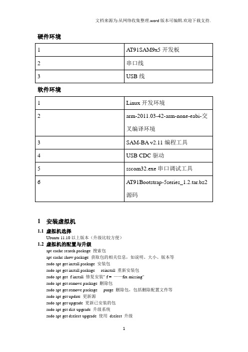
硬件环境软件环境1 安装虚拟机1.1虚拟机选择Ubuntu 11.10以上版本(升级比较方便)1.2虚拟机的配置与升级apt-cache search package 搜索包apt-cache show package 获取包的相关信息,如说明、大小、版本等sudo apt-get install package 安装包sudo apt-get install package - - reinstall 重新安装包sudo apt-get -f install 修复安装"-f = ——fix-missing"sudo apt-get remove package 删除包sudo apt-get remove package - - purge 删除包,包括删除配置文件等sudo apt-get update 更新源sudo apt-get upgrade 更新已安装的包sudo apt-get dist-upgrade 升级系统sudo apt-get dselect-upgrade 使用dselect 升级apt-cache depends package 了解使用依赖apt-cache rdepends package 是查看该包被哪些包依赖sudo apt-get build-dep package 安装相关的编译环境apt-get source package 下载该包的源代码sudo apt-get clean && sudo apt-get autoclean 清理无用的包sudo apt-get check 检查是否有损坏的依赖2 Linux下安装交叉编译环境2.1安装步骤1)下载arm-2011.03-42-arm-none-eabi-i686-pc-linux-2)命令行安装# tar xvzf arm-2011.03-42-arm-none-eabi-i686-pc-linux-# cd arm-2011.033 安装arm设备编程工具SAM Boot Assistant(SAM-BA)3.1 Windows下安装1)安装sam-ba_;2)安装USB CDC驱动;图 3.1图 3.2图 3.3图 3.4图 3.5图 3.7打开SAM-BA 2图 3.8图 3.93.2 Linux下安装1)解压sam-ba_;2)安装USB CDC驱动;1/ Login with administrator rights2/ Unload usbserial module if it is already running #rmmod usbserial3/ Load usbserial kernel module#modprobe usbserial vendor=0x03eb product=0x61244/ Verify that the USB connection is established#lsusb -d 03eb:6124Bus 004 Device 006: ID 03eb:6124 Atmel Corp5/ Know which USB connection is established#dmesgkernel: usb 4-2: new full speed USB device using uhci_hcd and address 5kernel: usb 4-2: configuration #1 chosen from 1 choicekernel: usbserial_generic 4-2:1.0: generic converter detectedkernel: usbserial_generic: probe of 4-2:1.0 failed with error -5kernel: usbserial_generic 4-2:1.1: generic converter detectedkernel: usb 4-2: generic converter now attached to ttyUSBx=> you will have to use /dev/ttyUSBx to connect to your boardRunning SAM-BA CDC Serial version :Launch 'sam-ba_cdc_ file, and select your board and the /dev/ttyUSBxdevice where your board in mounted on.- Update the kernel:# apt-get install linux-image-generic linux-headers-generic- On 64 bits version install 32 bits libraries:# apt-get install ia32-libs- Give sam-ba execute permission if needed:$ chmod +x sam-ba- Connect the board- Create a symlink on /dev/ttyACM0# ln -s /dev/ttyACM0 /dev/ttyUSB0- Launch sam-baTested on:Ubuntu 10.04 64 bits (Ubuntu 10.10 32 bits (Ubuntu 10.10 64 bits (Ubuntu 10.10 64 bits (Ubuntu 11.10 64 bits alpha3How to check if your kernel is up to date ?$ dmesgIf you have something like that (not exactly the same) it's ok:[227274.230016] usb 5-1: new full speed USB device using uhci_hcd and address 5[227274.395739] cdc_acm 5-1:1.0: This device cannot do calls on its own. It is not a modem.[227274.395768] cdc_acm 5-1:1.0: ttyACM0: USB ACM deviceIf you don't have this part: 'This device cannot do calls on its own. It is not a modem.',your kernel is probably not up to date or the cdc_acm patch has not been backported.4 示例4.1 下载AT91Bootstrap源码1)得到源码;2)解压# tar xvzf AT91Bootstrap-5series_#cd AT91Bootstrap-5series_1.24.2 配置AT91Bootstrap和选择启动媒介1) 从NAND FLASH启动#make at91sam9xnf_defconfig2)添加环境变量#vi .profilePATH="$PATH:/root/Public/arm-2011.03/bin"export PATH#souce .profile3)配置AT91Bootstrap#make menuconfig4.3 编译AT91Bootstrap#export $CROSS_COMPILE=” arm-none-eabi-”#make clear#make在../AT91Bootstrap-5series_1.2/binaries下产生at91sam9x5ek-nandflashboot- 4.4 使用AT91Bootstrap二进制文件1)从NAND flash启动A T91Bootstrap图 4.1在NAND和SPI无效的前提下,启动SAM-BA,烧AT91Bootstrap到NAND flash,如图4.1所示:(1)在SAM-BA图形用户界面上选择NandFlash媒介选项卡;(2)1)在NAND有效的前提下,在Scripts下拉列表框中选择“Enable NandFlash”;然后点击“Execute”按钮,完成NandFlash的初始化,如图4.2所示;图 4.2.12)清除芯片上原来烧的信息图 4.2.2结果如图 4.5所示。
- 1、下载文档前请自行甄别文档内容的完整性,平台不提供额外的编辑、内容补充、找答案等附加服务。
- 2、"仅部分预览"的文档,不可在线预览部分如存在完整性等问题,可反馈申请退款(可完整预览的文档不适用该条件!)。
- 3、如文档侵犯您的权益,请联系客服反馈,我们会尽快为您处理(人工客服工作时间:9:00-18:30)。
ARM-Based Products Group
2
1. Introduction
1. Introduction
NAND vs. NOR Flash
Advantage of NAND
XIP Memories used for booting purpose are:
Embedded Flash (SAM7, SAM9XE) External 16-bit Flash (SAM926x, SAM9R(L), SAM9G20…)
No boot program is executed, no initialization performed Whole microcontroller configuration must be made in the application, such as:
SAM9260
SAM9261(S) SAM9263 SAM9R(L)64
X
X X X
X
X X X
-
-
SAM9G10
SAM9G20 SAM9G45
X
X X
X
X
ARM-Based Products Group
-
13
X
2. Boot Solutions
NVM Memory Bootloader Application
ARM-Based Products Group
11
2. Boot Solutions
Booting from ROM
AT91SAM BootROM
NVM Memory Bootloader
SAM-BA Boot
FFPI
IAP Function
2nd Level Bootloader
ISP
ARM-Based Products Group
ARM-Based Products Group
14
2. Boot Solutions
Supported NVM Memories
Serial DataFlash: ATMEL AT45D and AT45DCB Serial Flash: Industry’s most advanced 25xxx compatible serial Flash (ATMEL AT25/26, SST, ST, Winbond…) SLC NandFlash: 8- and 16-bit, small and large blocks SDCard: any FAT12/16/32 formatted SD Cards which are not High Capacity SDHC
Power Up
Yes
BMS pin = 1
No
Boot From ROM
Boot From External 16-bit Flash
9
ARM-Based Products Group
2. Boot Solutions
2. Boot Solutions
Booting From an eXecute In Place Memory
NAND Flash
Programs stored cannot be executed directly Code Shadowing must be performed: memory contents must be first copied into memory-mapped RAM and executed there Used to replace Hard Disk Drive
ARM-Based Products Group
5
1. Introduction
AT91SAM Boot Strategies Introduction
To ensure maximum boot possibilities, memory layout can be changed with different parameters.
Gang Programmer Interface
IAP
12
2. Boot Solutions
BootROM Applications
Flash AT91 µC SAM7S SAM7X/XC SAM7SE SAM7L SAM9XE FlashLess AT91 µC NVM Bootloader SAM-BA Boot X X X X X FFPI X X X X X IAP Function X X
EEPROM: any I² Memory EEPROM C
ARM-Based Products Group
15
2. Boot Solutions
What is a valid code?
SD Card Example:
boot.bin file in the root directory of any FAT12/16/32 formatted SD Cards
16
2. Boot Solutions
What is a valid code (cont’d)?
DataFlash, NAND Flash, Serial Flash & EEPROM example:
The ARM exception vectors must have valid ARM instructions (B or LDR), excluding the 6th vector The 6th vector (reserved vector @ 0x14), must correspond to the size of the image to be copied in internal SRAM. Code size < AT91SAM internal SRAM size*
ARM-Based Products Group
4
1. Introduction
NOR vs. NAND Boot Considerations
NOR Flash
Used as an eXecute In Place (XIP) memory: no need to copy the program into RAM Used to replace ROM
High Speed Program/Erase Low Cost-per-bit High Capacity
Advantage of NOR
High Speed Random Access Byte Programming Code execution
Disadvantage of NAND
Slow Random Access Time Difficulty of Byte Programming
NMV Memory Bootloader called “NVM-Boot” is responsible for this copy NVM-Boot
Yes
Valid Code ?
No
Copy code from NVM memory into SRAM
Next NVM-Boot
Reset Peripherals, remap and execute code out of SRAM
ARM-Based Products Group
8
1. Introduction Boot Memory Selection for Flashless µC (SAM926x, SAM9R(L), SAM9G20) BMS pin is sampled when VDDCORE is powered.
Code size < AT91SAM internal SRAM size*
* Max code size value must be checked in the Boot Program section of each product datasheet ARM-Based Products Group
GPNVM bit
(Embedded Flash based µC)
OR
BMS pin
(Flashless µC)
Power Up
Boot Memory Selection
ARM-Based Products Group
6
1. Introduction
AT91SAM Boot Strategies Introduction (cont.)
Contrary to XIP memories, it is not possible to boot directly from a DataFlash, serial Flash, NAND Flash, SDCard or EEPROM
NVM Memory content must be first copied into memory-mapped RAM and executed there
Set thanks to the EFC Controller Cleared thanks to the EFC Controller or by asserting the ERASE pin.
Power Up
No
GPNVM bit = 1
Yes
Boot From ROM
Boot From Embedded Flash
Clocks configuration: Main Oscillator, PLL Embedded Flash Controller configuration (Wait States…) External Bus Interface configuration (Setup, Hold…)