LMCU板上的BA12003BF芯片达灵顿排号510167
WIFI模块-硬件设计资料

WIFI模块硬件设计规格书版本: 1.0目录1 模块总体介绍(Gerneral introduction) (4)1.1 概述及实物图片(Description) (4)1.2 应用领域(Application) (6)1.3 产品特性 (Main feature) (6)2 模块电气特性(Electric Characteristics) (8)2.1 极限条件(Absolute Maximum Ratings) (8)2.2 工作条件(Recommended Operate Range) (8)2.3 电气特性(General Electric Characteristics)............................... (8)2.4 拼脚定义(Pin Assignment and Description) (9)3 模块应用设计指导(Application note) (14)3.1 功能框图(Function Block description) (14)3.2 工作状态描述(state descriptions) (14)3.3 硬件应用接口概述 (15)3.4 电源和驱动应用接口 (16)3.4.1 电源和驱动管脚定义 (16)3.4.2 主电源供电特性Vbat (17)3.4.3 备用电池RTC................................................................................. ........................... (18)3.4.4 开关机及复位(Power ON/OFF and Reset) (19)3.4.5 充电输入口VCHGIN............................ ................................. .. (20)3.4.6 充电输出口VCHGOUT........................... ................................. . (21)3.4.7 电池检测专用ADC口ADC3/BAT_ID ........................... .. (21)3.4.8 4路LDO输出.................................................... .. (22)3.4.9 LED-驱动 (22)3.4.10 KEY_ LED-驱动 (23)3.4.11电源电路参考设计 (23)3.5 按键接口........................................... . (24)3.6 语音接口........................................... (25)3.6.1模拟音频差分输入主MIC0和辅助MIC1.................................................................................. . (25)3.6.2 模拟音频差分输出受话器REC (26)3.6.3 模拟音频差分输出喇叭SPK (26)3.7 UART 接口 (27)3.8 IIC 接口 (28)3.9 LCD IO驱动为2.8V SPI 接口 (28)3.10 LCD IO驱动为1.8V SPI 接口 (29)3.11 USB 接口..................................... . (30)3.12 SIM 卡接口 (31)3.13 T-F卡接口 (32)3.14 F M 接口 (34)3.15 BT 接口 (34)3.16 通用GPIO接口 (35)3.17 中断口EINT (35)3.18 模拟输入ADC (35)3.19 射频天线接口 (36)4硬件设计指南 (37)4.1 PCB板布局说明 (37)4.2 PCB 关键走线说明......................................................... (37)5 机械特性 (38)5.1 模块机械尺寸 (38)5.2 模块产品 Top-View 视图.......................................... (39)5.3模块供电要求及接法 (41)5.4下载软件 (41)5.5模块开机 (41)5.6 RF测试连接 (41)6 附录 (42)6.1 射频指标 (42)6.2 通信专用术语 (42)1 模块总体介绍1.1 概述及实物图片GW01_GSM&WIFI是一款GSM/GPRS/WIFI无线四频(GSM850/GSM900/DCS1800/PCS1900)工业模块,可以覆盖全球通用GSM频段。
8个达林顿管阵列芯片
8个达林顿管阵列芯片
达林顿管阵列芯片是一种集成了多个达林顿管的芯片,用于控制大电流驱动的装置。
以下是一些常见的8个达林顿管阵列芯片:
1. ULN2803:8位达林顿管阵列芯片,可用于驱动继电器、步进电机等设备。
2. ULN2003:8位达林顿管阵列芯片,常用于驱动小型电机、LED 显示屏等。
3. TPIC6B595:8位达林顿管阵列芯片,可用于驱动大功率负载,具有过载保护功能。
4. ULQ2803:8位达林顿管阵列芯片,适用于控制继电器、步进电机等高电流负载。
5. ULN2804:8位达林顿管阵列芯片,常用于驱动电流较大的负载。
6. SN754410:8位双向达林顿管阵列芯片,可用于驱动直流电机、步进电机等。
7. TIP120:8位达林顿管阵列芯片,适用于高电流应用,如驱动电机、灯光等。
8. L293D:8位双向达林顿管阵列芯片,常用于控制直流电机、步进电机等。
这些芯片都可以通过控制输入信号来控制相应的达林顿管输出,实现对大电流负载的驱动。
100V NPN 达林顿接驱电源芯片 SOT23 产品说明书
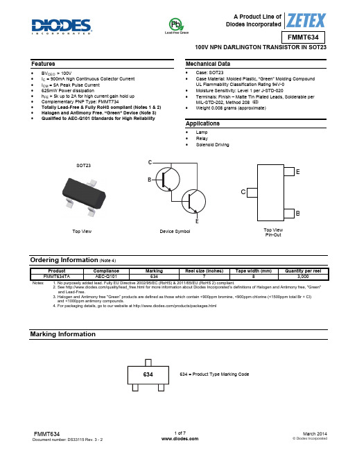
100V NPN DARLINGTON TRANSISTOR IN SOT23Features∙ BV CEO > 100V ∙ I C = 900mA high Continuous Collector Current ∙ I CM = 5A Peak Pulse Current ∙ 625mW Power dissipation ∙ h FE > 5k up to 2A for high current gain hold up ∙ Complementary PNP Type: FMMT734 ∙ Totally Lead-Free & Fully RoHS compliant (Notes 1 & 2) ∙ Halogen and Antimony Free. “Green” Device (Note 3) ∙ Qualified to AEC-Q101 Standards for High ReliabilityMechanical Data∙ Case: SOT23 ∙ Case Material: Molded Plastic, “Green” Molding CompoundUL Flammability Classification Rating 94V-0 ∙ Moisture Sensitivity: Level 1 per J-STD-020 ∙ Terminals: Finish – Matte Tin Plated Leads, Solderable perMIL-STD-202, Method 208 ∙ Weight 0.008 grams (approximate)Applications∙ Lamp ∙ Relay ∙ Solenoid DrivingOrdering Information (Note 4)Product Compliance Marking Reel size (inches) Tape width (mm)Quantity per reelFMMT634TA AEC-Q101 634 783,000Notes: 1. No purposely added lead. Fully EU Directive 2002/95/EC (RoHS) & 2011/65/EU (RoHS 2) compliant. 2. See /quality/lead_free.html for more information about Diodes Incorporated’s definitions of Halogen and Antimony free, "Green" and Lead-Free. 3. Halogen and Antimony free "Green” products are defined as those which contain <900ppm bromine, <900ppm chlorine (<1500ppm total Br + Cl) and <1000ppm antimony compounds.4. For packaging details, go to our website at /products/packages.htmlMarking Information634 = Product Type Marking CodeSOT23Top View Pin-OutTop ViewDevice SymbolCEB624634 EAbsolute Maximum Ratings(@T A = +25°C, unless otherwise specified.)UnitValueCharacteristic SymbolCollector-Base Voltage V CBO120 VCollector-Emitter Voltage V CEO100 VEmitter-Base Voltage V EBO12 VContinuous Collector Current I C900 mAPeak Pulse Current I CM 5 AThermal Characteristics (@T A = +25°C, unless otherwise specified.)UnitValueCharacteristic SymbolPower Dissipation (Note 5) P D625 mWPower Dissipation (Note 6) P D806 mWThermal Resistance, Junction to Ambient (Note 5) RθJA200 ︒C/WThermal Resistance, Junction to Ambient (Note 6) RθJA155 ︒C/WThermal Resistance, Junction to Leads (Note 7) RθJL194 ︒C/WOperating and Storage Temperature Range T J, T STG-55 to +150 ︒CESD Ratings (Note 8)UnitClassJEDECValueCharacteristic SymbolElectrostatic Discharge - Human Body Model ESD HBM 2,000 V 2Electrostatic Discharge - Machine Model ESD MM 200 V BNotes: 5. For a device mounted with the exposed collector pad on 25mm x 25mm 1oz copper that is on a single-sided 1.6mm FR4 PCB; device is measuredunder still air conditions whilst operating in a steady-state.6. Same as note (5), except the device is measured at t ≤ 5 sec.7. Thermal resistance from junction to solder-point (at the end of the collector lead).8. Refer to JEDEC specification JESD22-A114 and JESD22-A115.Thermal Characteristics and Derating information100m1101001m 10m100m110Single Pulse T amb =25°CV CE(s at)Limited100µs1ms10ms100ms1s DCSafe Operating AreaI C C o l l e c t o r C u r r e n t (A )V CE Collector-Emitter Voltage (V)2550751001251501750.00.10.20.30.40.50.60.7Derating CurveTemperature (°C)M a x P o w e r D i s s i p a t i o n (W )20406080100120140160180200220Transient Thermal ImpedanceT h e r m a l R e s i s t a n c e (°C /W )Pulse Width (s)0.1110100Pulse Power DissipationPulse Width (s)M a x i m u m P o w e r (W )Electrical Characteristics (@T A = +25°C, unless otherwise specified.)Characteristic Symbol Min Typ Max Unit Test ConditionCollector-Base Breakdown Voltage BV CBO 120 170 - V I C = 100µACollector-Emitter Breakdown Voltage (Note 9) BV CEO 100 115 - V I C = 10mAEmitter-Base Breakdown Voltage BV EBO 12 16 - V I E = 100µA Collector Cut-off Current I CBO - <1 10 nA V CB = 80V Emitter Cut-off Current I EBO - <1 10 nA V EB = 7V Collector Emitter Cut-off Current I CES - <1 100 nA V CES = 80VStatic Forward Current Transfer Ratio (Note 9) h FE- 20k 15k 5k - - 50k 60k 40k 14k 24k 600 ---- - - - I C = 10mA, V CE = 5V I C = 100mA, V CE = 5V I C = 1A, V CE = 5V I C = 2A, V CE = 5V I C = 1A, V CE = 2V I C = 5A, V CE = 5VCollector-Emitter Saturation Voltage (Note 9) V CE(sat)- - - - - - 0.67 0.72 0.75 0.82 0.68 0.85 0.750.800.850.93 - 0.96 V I C = 100mA, I B = 1mA I C = 250mA, I B = 1mA I C = 500mA, I B = 5mA I C = 900mA, I B = 5mA I C = 900mA, I B = 5mA, T J =+150°C I C = 1A, I B = 5mABase-Emitter Saturation Voltage (Note 9) V BE(sat) - 1.5 1.65 V I C = 1A, I B = 5mA Base-Emitter Turn-On Voltage (Note 9) V BE(on) - 1.33 1.50 V I C = 1A, V CE = 5VTransition Frequency f T- 140 - MHz I C = 50mA, V CE = 10V,f = 100MHzOutput Capacitance C obo - 9 20 pF V CB = 10V, f = 1MHz Turn-On Time t (on) - 290 - ns V CC = 20V, I C = 500mA,I B1 = -I B2 = 1mATurn-Off Time t (off) - 2,400 - ns Notes:9. Measured under pulsed conditions. Pulse width ≤ 300µs. Duty cycle ≤ 2%Typical Electrical Characteristics (@T A = +25°C, unless otherwise specified.)Package Outline DimensionsPlease see AP02002 at /datasheets/ap02002.pdf for latest version.Suggested Pad LayoutPlease see AP02001 at /datasheets/ap02001.pdf for the latest version.Note:For high voltage applications, the appropriate industry sector guidelines should be considered with regards to creepage and clearance distancesbetween device Terminals and PCB tracking.SOT23Dim Min Max Typ A 0.37 0.51 0.40 B 1.20 1.40 1.30 C 2.30 2.50 2.40 D 0.89 1.03 0.915 F 0.45 0.60 0.535 G 1.78 2.05 1.83 H 2.80 3.00 2.90 J 0.013 0.10 0.05 K 0.890 1.00 0.975 K1 0.903 1.10 1.025 L 0.45 0.61 0.55 L1 0.25 0.55 0.40 M 0.085 0.150 0.110 a 8°All Dimensions in mmDimensions Value (in mm)Z 2.9 X 0.8 Y 0.9C2.0 E1.35 X EYCZA l l 7°IMPORTANT NOTICEDIODES INCORPORATED MAKES NO WARRANTY OF ANY KIND, EXPRESS OR IMPLIED, WITH REGARDS TO THIS DOCUMENT, INCLUDING, BUT NOT LIMITED TO, THE IMPLIED WARRANTIES OF MERCHANTABILITY AND FITNESS FOR A PARTICULAR PURPOSE (AND THEIR EQUIVALENTS UNDER THE LAWS OF ANY JURISDICTION).Diodes Incorporated and its subsidiaries reserve the right to make modifications, enhancements, improvements, corrections or other changes without further notice to this document and any product described herein. Diodes Incorporated does not assume any liability arising out of the application or use of this document or any product described herein; neither does Diodes Incorporated convey any license under its patent or trademark rights, nor the rights of others. Any Customer or user of this document or products described herein in such applications shall assume all risks of such use and will agree to hold Diodes Incorporated and all the companies whose products are represented on Diodes Incorporated website, harmless against all damages.Diodes Incorporated does not warrant or accept any liability whatsoever in respect of any products purchased through unauthorized sales channel. Should Customers purchase or use Diodes Incorporated products for any unintended or unauthorized application, Customers shall indemnify and hold Diodes Incorporated and its representatives harmless against all claims, damages, expenses, and attorney fees arising out of, directly or indirectly, any claim of personal injury or death associated with such unintended or unauthorized application.Products described herein may be covered by one or more United States, international or foreign patents pending. Product names and markings noted herein may also be covered by one or more United States, international or foreign trademarks.This document is written in English but may be translated into multiple languages for reference. Only the English version of this document is the final and determinative format released by Diodes Incorporated.LIFE SUPPORTDiodes Incorporated products are specifically not authorized for use as critical components in life support devices or systems without the express written approval of the Chief Executive Officer of Diodes Incorporated. As used herein:A. Life support devices or systems are devices or systems which:1. are intended to implant into the body, or2. support or sustain life and whose failure to perform when properly used in accordance with instructions for use provided in thelabeling can be reasonably expected to result in significant injury to the user.B. A critical component is any component in a life support device or system whose failure to perform can be reasonably expected to cause thefailure of the life support device or to affect its safety or effectiveness.Customers represent that they have all necessary expertise in the safety and regulatory ramifications of their life support devices or systems, and acknowledge and agree that they are solely responsible for all legal, regulatory and safety-related requirements concerning their products and any use of Diodes Incorporated products in such safety-critical, life support devices or systems, notwithstanding any devices- or systems-related information or support that may be provided by Diodes Incorporated. Further, Customers must fully indemnify Diodes Incorporated and its representatives against any damages arising out of the use of Diodes Incorporated products in such safety-critical, life support devices or systems.Copyright © 2014, Diodes Incorporated。
ULN2803达林顿阵列功率驱动集成电路说明书

达林顿阵列功率驱动集成电路概述ULN2803是高耐压、大电流达林顿阵列,由八个NPN 达林顿管组成。
所有单元共用发射极,每个单元采用开集电极输出。
每一对达林顿都串联一个2.7K 的基极电阻,直接兼容TTL 和5V CMOS 电路,可以直接处理原先需要标准逻辑缓冲器来处理的数据。
ULN2803 工作电压高,工作电流大,灌电流可达500mA ,并且能够在关态时承受50V 的电压,输出还可以在高负载电流下并行运行,很好的提供了需要多接口驱动电路的解决方案。
特点♦ 工作电压范围宽 ♦ 八路高增益达林顿阵列 ♦ 输出电压高(可达50V ) ♦ 输出电流大(可达500mA ) ♦ 可与TTL 、CMOS 、PMOS 直接连接 ♦内置钳位二极管适应感性负载应用♦ 继电器驱动 ♦ 直流照明驱动 ♦ 步进电机驱动 ♦ 电磁阀♦直流无刷电机驱动产品名称封装打印名称包装包装数量DIP18ULN2803管装800只/盒SOP18ULN2803编带2000只/盘产品订购信息ULN2803ADN ULN2803ADM/TR电路框图GNDULN2803 管脚说明表极限参数电气特性参数(除非特别指定Ta=25°C)注:1、极限值是指超出该范围,器件有可能被损坏,并非器件的正常工作条件范围。
电参数表提供了器件的工作条件范围;2、除特别指明外,所有条件适用于达林顿阵列;3、通常条件下,每路输出在 70°C、VCE (Sat)= 1.6V 下脉冲宽度为 20ms 的持续工作电流为350mA。
典型特性曲线集电极峰值电流 - m ADUTY CYCLE - %图 4. 集电极峰值电流vs.几路同时导通1004006080100集电极电流 - m A饱和压降 - V图1. 集电极电流vs. 饱和压降2000.580004006001.01.52003002040集电极电流 - m A输入电流 - uA图2. 集电极电流vs. 输入电流1002004000200300400600输入电流 - m A输入电压 - V 图3. 输入电流vs. 输入电压0.542.501.02.02691.53578内部等效线路图INOUTCOMMON测试线路图OPEN+50VC图2C图7图3COPEN+50V 图8OPENF封装外形图重要声明:华冠半导体保留未经通知更改所提供的产品和服务。
tms320f28335中文数据手册介绍

光耦达林顿晶体芯片

光耦(Optocoupler)是一种能够将电气信号通过光信号进行隔离传输的器件。
达林顿晶体芯片(Darlington Transistor Array)是一种由多个达林顿晶体管组成的集成电路。
光耦达林顿晶体芯片结合了光耦和达林顿晶体芯片的功能,提供了高电压隔离和高电流驱动的能力,常用于电气隔离和信号传输的应用中。
光耦达林顿晶体芯片通常由以下几部分组成:
1. 发光二极管(LED):负责将电信号转换成光信号。
电流通过LED产生光,光强度与输入电流成正比。
2. 光敏二极管(Phototransistor):接收LED发出的光信号,并将其转换为电流信号。
光敏二极管的电流放大倍数高,通常用作输入信号的驱动器。
3. 达林顿晶体管(Darlington Transistor):由多个晶体管级联组成。
它们提供了高电流放大(电流放大倍数高)的能力。
在光耦达林顿晶体芯片中,达林顿晶体管用于放大光敏二极管的输出电流信号。
光耦达林顿晶体芯片在工业控制、通信设备、电力电子等领域得到广泛应用。
由于它能够实现电气隔离和信号传输,提供了安全性和可靠性的保证,以及较高的电流放大能力,因此在不同的电路设计中使用光耦达林顿晶体芯片能带来便利和优势。
HPMLDL系列服务器

HPMLDL系列服务器hpML系列服务器HP ProLiant ML110G7(C8R00A)参数规格差不多参数产品类型工作组级产品类别塔式产品结构4U处理器CPU类型奔腾双核CPU型号奔腾双核G860CPU频率3GHzHP ProLiant ML330 G6(600911-AA1)参数规格差不多参数产品类型企业级产品类别塔式产品结构5U处理器CPU类型Intel 至强5600CPU型号Xeon E5620CPU频率 2.4GHz智能加速主2.666GHz频标配CPU1颗数量最大CPU2颗数量制程工艺32nm三级缓存12MB总线规格QPI 5.86GT/sCPU核心四核HP ProLiant ML330 G6(B9D22A)参数规格差不多参数产品类型企业级产品类别塔式产品结构5U处理器CPU类型Intel 至强5600 CPU型号Xeon E5606CPU频率 2.13GHz标配CPU1颗数量最大CPU2颗数量制程工艺32nm三级缓存8MB总线规格QPI 4.8GT/sHP ProLiant ML330 G6(600911-AA1)参数规格差不多参数产品类型企业级产品类别塔式产品结构5U处理器CPU类型Intel 至强5600CPU型号Xeon E5620CPU频率 2.4GHz智能加速主2.666GHz频标配CPU1颗数量最大CPU2颗数量制程工艺32nm三级缓存12MB总线规格QPI 5.86GT/sCPU核心四核HP ProLiant ML350 G6(638180-AA1)参数规格差不多参数产品类别塔式产品结构5U处理器CPU类型Intel 至强5600CPU型号Xeon E5606CPU频率 2.13GHz标配CPU1颗数量最大CPU2颗数量制程工艺32nm三级缓存8MB总线规格QPI 4.8GT/sCPU核心四核CPU线程四线程数主板HP ProLiant ML350 G6(600431-AA5)参数规格差不多参数产品类别塔式产品结构5U处理器CPU类型Intel 至强5600CPU型号Xeon E5620CPU频率 2.4GHz智能加速主2.666GHz频标配CPU1颗数量最大CPU2颗数量制程工艺32nm三级缓存12MB总线规格QPI 5.86GT/sCPU核心四核CPU线程八线程数HP ProLiant ML350 G6(594869-AA1)参数规格差不多参数产品类别塔式产品结构5U处理器CPU类型Intel 至强5600CPU型号Xeon E5620CPU频率 2.4GHz智能加速主2.666GHz频标配CPU1颗数量最大CPU2颗数量制程工艺32nm三级缓存12MB总线规格QPI 5.86GT/sCPU核心四核CPU线程八线程数HP ProLiant ML310e Gen8(686146-AA5)参数规格差不多参数产品类型企业级产品类别塔式产品结构4U处理器CPU类型Intel 至强E3-1200 v2 CPU型号Xeon E3-1220 v2CPU频率 3.1GHz标配CPU1颗数量最大CPU4颗数量制程工艺22nm三级缓存8MB总线规格DMI 5GT/sHP ProLiant ML310e Gen8(686147-AA5)参数规格差不多参数产品类型企业级产品类别塔式产品结构4U处理器CPU类型Intel 至强E3-1200 v2 CPU型号Xeon E3-1240 v2CPU频率 3.4GHz智能加速主3.8GHz频标配CPU1颗数量最大CPU4颗数量制程工艺22nm三级缓存8MBHP ProLiant ML350e Gen8(C3Q10A)参数规格差不多参数产品类型企业级产品类别塔式产品结构5U处理器CPU类型Intel 至强E5-2400 CPU型号Xeon E5-2403CPU频率 1.8GHz标配CPU1颗数量最大CPU4颗数量制程工艺32nm三级缓存10MB总线规格QPI 6.4GT/sHP ProLiant ML350e Gen8(C3Q08A)参数规格差不多参数产品类型企业级产品类别塔式产品结构5U处理器CPU类型Intel 至强E5-2400 CPU型号Xeon E5-2407CPU频率 2.2GHz标配CPU1颗数量最大CPU4颗数量制程工艺32nm三级缓存10MB总线规格QPI 6.4GT/sHP ProLiant ML350e Gen8(C3Q09A)参数规格差不多参数产品类型企业级产品类别塔式产品结构5U处理器CPU类型Intel 至强E5-2400 CPU型号Xeon E5-2420CPU频率 1.9GHz标配CPU1颗数量最大CPU4颗数量制程工艺32nm三级缓存15MB总线规格QPI 6.4GT/sHP ProLiant ML350e Gen8(C3F91A)参数规格差不多参数产品类型企业级产品类别塔式产品结构5U处理器CPU类型Intel 至强E5-2400 CPU型号Xeon E5-2430CPU频率 2.2GHz标配CPU1颗数量最大CPU4颗数量制程工艺32nm三级缓存15MB总线规格QPI 6.4GT/sHP ProLiant ML350p Gen8(646675-AA1)参数规格差不多参数产品类别塔式产品结构5U处理器CPU类型Intel 至强E5-2600 CPU型号Xeon E5-2609CPU频率 2.4GHz标配CPU1颗数量最大CPU2颗数量制程工艺32nm三级缓存10MB总线规格QPI 6.4GT/sHP ProLiant ML350p Gen8(668271-AA5)参数规格差不多参数产品类别塔式产品结构5U处理器CPU类型Intel 至强E5-2600 CPU型号Xeon E5-2620CPU频率2GHz智能加速主2.5GHz频标配CPU1颗数量最大CPU2颗数量制程工艺32nm。
亚历山大-伯兰迪 8位灰码编码器输入模块说明书

1AllenĆBradleyGray Encoder (12Ć24 VDC)Input Module (Cat. No. 1771-DL)Product Data The Gray Encoder (12-24 VDC) Input Module converts an 8-bit Gray codefrom an absolute encoder to an 8-bit binary number for input to anAllen-Bradley programmable controller.The module also has a 120 V AC zero-speed triac switch which is on whilethe Gray encoder is in motion. The switch turns off after a selectable delaywhen the module detects that motion has stopped. You can use this switchas a safety interlock to open the drive circuit after motion stops or if theencoder should fail.The Allen-Bradley 8-bit Gray Encoder (Bulletin 845A-SJZ3DN6DW iscompatible with this encoder module.The encoder module is shipped with wiring arm (cat. no. 1771-WB).Description2The module receives its inputs from an encoder that detects rotational position, 0-360°, and converts position values to a corresponding 8-bit Gray code, 0-255. The encoder transmits coded position values to the module over a multiconductor cable (figure 1).Figure 1Block Diagram of Encoder and ModuleModule OutputsThe module converts 8-bit Gray code to 8-bit binary, and places these values on the backplane of the I/O chassis. The processor or remote I/O adapter reads these values in the same manner it reads data from a discrete I/O module. Values are read into the processor’s input image table word address corresponding to the module’s location in the I/O chassis: upper byte for slot 1, lower byte for slot 0.Zero Speed SwitchThe encoder module has a zero-speed triac switch (between terminals 11 and 12) which remains on until the module detects that motion has stopped.An adjustable time delay opens the switch after a delay. You adjust the delay time between 0.3 and 6.0 seconds using the trim pot located under the zero-speed indicator on the front of the module: counter-clockwise for shorter delay, clockwise for longer delay. It is factory set for 6.0 seconds.Module Inputs3The switch is rated at 0.5 A at 120 V AC, 47-63 Hz. Use this switch only toopen a “sealed-in” circuit (figure 2) such as for a motor starter. Do not useto initiate a “sealed-in” circuit.Figure 2Zero Speed Switch CircuitYou may need additional surge suppression to protect the triac switch fromthe motor starter. A load with large inductive characteristics can generatevoltage transients which exceed the switch’s internal surge current rating.Since switching frequency and load impedance vary with application, wecannot specify a particular suppressor for your motor starter. The tablebelow offers some suggestions for selecting a suppressor.The module has a 1 A fuse located on the circuit board inside the module.This fuse is in series with the triac switch, and will blow if the maximumsurge current exceeds 2 A for 10 ms.4Electrostatic DamageUnder some conditions, electrostatic discharge can degrade performance or damage the module. If you observe the following precautions you can guard against electrostatic damage.Touch a grounded object to discharge yourself before handling themodule.Do not touch the backplane connector or connector pins.When replacing the fuse, do not touch other circuit components inside the module. If available, use a static-safe work station.Replacing the FuseReplace the fuse as follows:Remove cover by unscrewing four corner screws.Remove the circuit board and turn it over.Locate the fuse on the lower side, and replace.Re-assemble in reverse order.Status IndicatorsThe front panel of the encoder module contains nine red LED status indicators.The top indicator lights when the zero-speed triac switch is ON. Each of the remaining eight indicators corresponds to a single Gray code bit, and lights when the logic state of the bit is OFF.The encoder module requires 120 mA from the I/O chassis power supply. Total this amount with the current requirements of other modules in the chassis to guard against overloading the backplane and backplane power supply.Backplane Power5Customer Power SupplyThe module also requires a 12 to 24 VDC power supply which you connect to the wiring arm and absolute encoder (figure 3). The encoder driving circuit sinks 15 mA at 24 VDC or 6 mA at 12 VDC per Gray code input.Multiply this by eight for each encoder powered by this supply. Some absolute encoders may require an additional 5 VDC supply.Figure 3Wiring Diagram Use Belden 9556 multiconductor shielded cable (or equivalent) to connectthe encoder to the module’s wiring arm (figure 3). Ground the cable at oneend, only. We recommend that you ground it at an I/O chassis mountingstud. Wrap the drain wire and shield together and connect both to themounting stud. Limit the cable length to 50 feet.Wiring6WARNING: Remove power from the 1771 I/O chassisbackplane and wiring arm before removing or installing an I/Omodule.Failure to remove power from the backplane or wiring armcould cause module damage, degradation of performance, orinjury.Failure to remove power from the backplane could causeinjury or equipment damage due to possible unexpectedoperation.Plastic keying bands are shipped with each I/O chassis. These bands help ensure that only a selected type of module can be placed in a particular module slot. They also help to align the module with the backplane connector.Each module is slotted at its rear edge. The position of the keying bands on the upper backplane connector must correspond to these slots to allow insertion of the module. For the 1771-DL Gray Encoder Module, position the keying bands as follows:Between 4 and 6Between 24 and 26Keying7Input G one 8Ćbit Absolute Gray Encoder Digital Resolution G 1 part in 256HighĆtrue Logic G from a 7406, 7407, or equivalent TTL circuit with an open collector output G module sources current to user device Logic State G logic 1: 10Ć27 VDC G logic 0 : 0Ć2 VDC Input Sourcing Current G 6 mA per bit at 10 VDC G 15 mA per bit at 27 VDC Input Filter Time Delay G 1 millisecond (max.)Backplane Current G 120 mA at 5 VDC ZeroĆSpeed Triac SwitchG output voltage:120 VAC (92Ć138 VAC,47Ć63 Hz)G output time delay:adjustable from 0.3 to 6.0seconds(factory set at 6 seconds)G continuous output current:0.5 A (max.)G maximum surge current:2 A for 10 msG minimum load current:50 mAG ON state" voltage drop:2V at 100 mA load currentG OFF state" leakage current:5 mA (max.)G output fuse:8 AG, 1 A normal blowEnvironmental ConditionsG operating temperature:0 to 60° C (32 to 140° F)G storage temperature:-40 to 85° C (-40 to 185° F)G relative humidity:5 to 95% (without condensation)Keying Band PositionsG between 4 and 6G between 24 and 26© 1986 Allen-Bradley CompanyPLC is a registered trademark of Allen-Bradley CompanySpecifications8With offices in major cities worldwideWORLD HEADQUARTERS Allen-Bradley 1201 South Second Street Milwaukee, WI 53204 USA Tel: (1) 414 382-2000Telex: 43 11 016FAX: (1) 414 382-4444EUROPE/MIDDLE EAST/AFRICA HEADQUARTERS Allen-Bradley Europe B.V .Amsterdamseweg 151422 AC Uithoorn The Netherlands Tel: (31) 2975/43500Telex: (844) 18042FAX: (31) 2975/60222ASIA/PACIFIC HEADQUARTERS Allen-Bradley (Hong Kong)Limited Room 1006, Block B, Sea View Estate 28 Watson Road Hong Kong Tel: (852) 887-4788Telex: (780) 64347FAX: (852) 510-9436CANADA HEADQUARTERS Allen-Bradley Canada Limited 135 Dundas Street Cambridge, Ontario N1R 5X1Canada Tel: (1) 519 623-1810FAX: (1) 519 623-8930LATIN AMERICA HEADQUARTERS Allen-Bradley 1201 South Second Street Milwaukee, WI 53204 USA Tel: (1) 414 382-2000Telex: 43 11 016FAX: (1) 414 382-2400As a subsidiary of Rockwell International, one of the world’s largest technology companies — Allen-Bradley meets today’s challenges of industrial automation with over 85 years of practical plant-floor experience. More than 11,000 employees throughout the world design, manufacture and apply a wide range of control and automation products and supporting services to help our customers continuously improve quality, productivity and time to market. These products and services not only control individual machines but integrate the manufacturing process, while providing access to vital plant floor data that can be used to support decision-making throughout the enterprise.Publication 1771-2.29 — June 1986Supersedes Publication 1771-941 — September 1981PN 955099-78Printed in USA。
- 1、下载文档前请自行甄别文档内容的完整性,平台不提供额外的编辑、内容补充、找答案等附加服务。
- 2、"仅部分预览"的文档,不可在线预览部分如存在完整性等问题,可反馈申请退款(可完整预览的文档不适用该条件!)。
- 3、如文档侵犯您的权益,请联系客服反馈,我们会尽快为您处理(人工客服工作时间:9:00-18:30)。
Standard ICsHigh voltage, high current Darlington transistor arrayBA12001B / BA12003B / BA12003BF / BA12004BThe BA12001B, BA12003B, BA12003BF, and BA12004B are high voltage, high current, high sustain voltage transistor arrays consisting of seven circuits of Darlington transistors.Because it incorporates built-in surge-absorbing diodes and base current-control resistors needed when using inductive loads such as relay coils, attachments can be kept to a minimum.With an output sustain voltage as high as 60V and an output current (sink current) of 500mA, this product is ideal for use with various drivers and as an interface with other elements.z ApplicationsDrivers for LEDs, lamps, relays and solenoidsInterface with other elementsz Features1) High output current. (I OUT=500mA Max.)2) High output sustain voltage. (V OUT=50V Max.)3) Seven Darlington transistors built in.4) Built-in surge-absorbing clamp diode.(Note : Refer to the “Reference items when using in application.” )z Block diagramStandard ICsz Internal circuit configurationINGNDFig.1 BA12001B INCOMOUTGNDFig.2 BA12003B / BFINCOMOUTGNDFig.3 BA12004Bz Absolute maximum ratings (T a=25°C)ParameterSymbol Limits Unit V CE 60V Input voltage Input current V IN −0.5∼+30V other than BA12001BBA12001BDIP package SOP package I IN 25Output current I OUT 500Ground pin current I GND 2.3∗1A Power dissipationPd 1250∗2625∗3mW Diode reverse voltage V R 60V Diode forward current I F 500mA Operating temperature Topr −25∼+75˚C Storage temperatureTstg−55∼+150˚CmA / unit mA / unitPower supply voltage ∗1 Pulse width ≤ 20ms, duty cycle ≤ 10%, same current for all 7 circuits ∗2 Reduced by 10mW for each increase in Ta of 1˚C over 25˚C .∗3 Reduced by 50mW for each increase in Ta of 1˚C over 25˚C .z Recommended operating conditions (T a=25°C)ParameterSymbol Min.Typ.Max.Unit Conditions Output current I OUT −−350mA Fig.9, 10Power supply voltageV CE −−55V −Input voltage (excluding BA12001B)V IN −−30V −Input current (BA12001B only)I IN−−25−mA / unitStandard ICsz Electrical characteristics (T a=25°C)ParameterSymbol Min.Typ.Max.Unit ConditionsOutput leakage current I L −010µA V CE = 60VDC current transfer ratioh FE10002400−VOutput saturation voltageV CE(sat)−0.941.1V 1.14 1.31.461.6Input voltageV IN −V 1.7522.535V IN−V 1.91 2.42.756V IN −V2.173.43.278Input currentI IN −mA V IN = 3.85V 0.90 1.35BA12003B / BF BA12004BBA12003B / BF BA12004B BA12003B / BF BA12004BBA12003B / BF BA12004B0.390.5Diode reverse current I R −050µA V R = 60V Diode forward voltage V F − 1.732V I F = 350mA Input capacitanceC IN−30−pFV CE = 2V, I OUT = 350mA I OUT = 100mA, I IN = 250µA I OUT = 200mA, I IN = 350µA I OUT = 350mA, I IN = 500µAV CE = 2V, I OUT = 100mA V CE = 2V, I OUT = 200mA V CE = 2V, I OUT = 350mA V IN = 5V V IN = 0V, f = 1MHzNote: Input voltage and input current for BA12001 vary based on external resistor.z Measurement circuits(1) Output leakage current I L(sat)(2) DC current transfer ratioOutput saturation voltageI II O V CE (sat)h FE =(3) Input voltage VINOPEN(4) Input current I IN(5) Diode reverse current I R(6) Diode forward voltage IF(7) Input capacitance C INFig.4Standard ICsz Application exampleRY (1) Relay driver(2) LED driver Fig.5z Application notesThe BA12001B is a transistor array which can be directly coupled to a general logic circuit such as PMOS, CMOS, or TTL.A current limiting resistor needs to be connected in series with the input.The BA12003B / BF can be coupled directly to TTL or CMOS output (when operating at 5V). In order to limit the input current to a stable value, resistors are connected in series to each of the inputs.The BA12004B is designed for direct coupling to CMOS or PMOS output using a 6 to 15V power supply voltage. In order to limit the input current to a stable value, resistors are connected in series to each of the inputs.The load for each of these products should be connected between the driver output and the power supply. T o protect the IC from excessive swing voltage, the COM pin (Pin 9) should be connected to the power supply.Fig.6 shows the configuration of the on-chip diode for surge absorption.In the construction of the surge-absorbing diode,there is an N-P junction between the N-layer (N-well + BL) and the substrate (P-sub) so that when the diode is on, current flows from the output pin to the substrate. In terms of the vertical construction, this diode is configured similar to a PNP transistor. When using the surge-absorbing diode, take appropriate measures regarding the thermal characteristics of the design considering the current that will be handled.Also, if motor back-rush current or other conditions that will result continued surge current to flow to the surge-absorbing diode can be foreseen, we strongly recommend connecting a Schottky barrier diode (or other type of diode with a low foward voltage) in parallel with the surge-absorbing diode to construct a bypass route for the surge current.Fig.6 Vertical construction of the surge-absorbing diodeStandard ICsz Electrical characteristic curvesP O W E R D I S S I P A T I O N : P d (m W )AMBIENT TEMPERATURE : Ta (˚C)Fig.7 Power dissipation vs. ambient temperatureO U T P U T C U R R E N T : I O (m A )DUTY CYCLE : (%)Fig.8 Output conditions (I)O U T P U T C U R R E N T : I O U T(m A )DUTY CYCLE (%)Fig.9 Output conditions (II)O U T P U T C U R R E N T: I O U T (m A )SUPPLY VOLTAGE: V CC (V)Fig.10 Usage conditions range per circuitD C C U R RE N T G A I N : hF EOUTPUT CURRET : I OUT (mA)500020001000100200500Ta = 25˚C V CE = 2.0V1020501002005001000Fig.11 DC current transfer ratio vs. output currentO U T P U T C U R R E N T : I O U T (m A )COLLECTOR TO EMITTER VOLTAGE : V CE(V)Fig.12 Output current vs. voltage between collector and emitterO U T P U T C U R R E N T : I O U T (m A )COLLECTOR TO EMITTER VOLTAGE : V CE (V)Fig.13 Output current vs. voltage between collector and emitterO U T P U T C U R R E N T : I O U T (m A )COLLECTOR TO EMITTER VOLTAGE : V CE(V)Fig.14 Output current vs. voltage between collector and emitterI N P U T C U R R E N T : I I N (m A )INPUT VOLTAGE : V IN (V)201510510203040Ta = −25˚C Ta = 25˚C Ta = 75˚CFig.15 Input current vs. input voltage (BA12003B / BF)Standard ICsINPUT VOLTAGE : V IN (V)I N P U T C U R R E N T : I I N (m A )Fig.16 Input current vs. input voltage (BA12004B)O U T P U T V O L T A G E : V C E O U T (V )INPUT VOLTAGE : V IN (V)Fig.17 Output voltage vs. input voltage (BA12003B / BF)O U T P U T V O L T A G E : V O U T (V ), V C E (V)INPUT VOLTAGE : V IN (V), V I (V)Fig.18 Output voltage vs. input voltage (BA12004B)z External dimensions (Units : mm)。