2001-Sigmund-A 99 line topology optimization c
TheoreticalAndAppliedFractureMechanics,1992…

Theoretical And Applied Fracture Mechanics, 1992-1993 Bound Issues By G. C. SihIf you are searched for the ebook Theoretical and Applied Fracture Mechanics, 1992-1993 Bound Issues in pdf format, then you have come on tofaithful site. We presented complete variation of this ebook in doc, PDF, ePub, txt, DjVu forms. You may readTheoretical and Applied Fracture Mechanics, 1992-1993 Bound Issues online theoretical-and-applied-fracture-mechanics-1992-1993-bound-issues.pdf either load. Withal, on oursite you may reading guides and other artistic eBooks online, or downloading their. We will invite attention thatour website not store the eBook itself, but we give reference to website where you can load either reading online.If you have must to downloading pdf Theoretical and Applied Fracture Mechanics, 1992-1993 Bound Issues, then you have come on to correctsite. We have Theoretical and Applied Fracture Mechanics, 1992-1993 Bound Issues DjVu, doc, PDF, txt, ePub forms. We will be pleased if youreturn anew.theor appl fract mech - theoretical and applied - Theoretical and Applied Fracture Mechanics,THEOR APPL FRACT MECH,Electrical & Electronic Engineering,Nuclear Engineering,Ocean Engineeringeffects of fractal crack - sciencedirect - which considers the effects of fractal H. Xie /Theoretical and Applied Xie / Theoretical and Applied Fracture Mechanics Crack Problems, ed. G.C. Sihthe carter n. paden, jr. distinguished chair in - 1995 | 1994 | 1993 | 1992 Special Issue of the Theoretical and Applied Fracture Mechanics, Mechanics Problems, eds. G.C. Sih andtheoretical and applied fracture mechanics - Find out more about the editorial board for Theoretical and Applied Fracture Mechanics.publications. books. research papers.genady - Proceedings of the Conference on Fracture Mechanics and Technology, (G. Sih, Theoretical and Applied Mechanics, problems of fracture mechanics.on the finite element analysis of inverse problems - Inverse problems in fracture mechanics 481 G. (1993), Propagation and fracture energy of interface Sih, G.C. (1974),zheng* the state key laboratory for mechanical - in Progress in Fracture Mechanics, G.C. Sih and Theoretical and Applied Fracture Mechanics 18 (1993) Theoretical and Applied Fracture Mechanics 17 (1992)verification of brittle fracture criteria for - Computational Methods in Fracture Mechanics, Acta Mechanica et Automatica, Sih G.C. (1965), Plane Problems of Cracks in Dissimilar Media.: g. c. sih: books, biogs, audiobooks, - Visit 's G. C. Sih Page and shop for all G. C. Sih books. Check out pictures, bibliography, biography and community discussions about G. C. Sihjournal " mechanics of solids" - archive of issues - "Fracture mechanics applied to glass fibre/epoxy matrix interface characterization No. 3, pp. 423-459, 1992. 233. G. C. Papanicolaou and D G. C. Sihtheoretical and applied fracture mechanics | vol - Theoretical and Applied Fracture Mechanics Volume 75, Pages 1-160 (February 2015)citeulike: theoretical and applied fracture - Articles from the last few issues of Theoretical and Applied Fracture Mechanics Elsevier. Search Export Show Details Hide Detailstheoretical and applied fracture mechanics - Theoretical and applied fracture mechanics. Home. WorldCat Home About WorldCat Help Feedback. Search. Search for Library Items Search for Lists Search formathematical research in materials science: - Fluid Mech. 22:13 34. Denn, M. M. 1992. Pp. 45 49 in Theoretical and Applied of Fracture Mechanics in Modern Technology. G. C problems in materialsrigid-plastic and damage behavior in metal - Theoretical and Applied Fracture Mechanics 18 G.C. Sih, Mechanics of Fracture Theoretical and Applied Fracture Mechanics 18 (1) 31-45 (1992). [21] G.C. Sihfinite element analysis of sheet forming processes - H. D. (1990), Finite element analysis of sheet forming Theoretical and Applied Fracture Mechanics, 1993, Theoretical and Applied Fracture Mechanics,theoretical and applied fracture mechanics | - Theoretical and Applied Fracture Mechanics: Aims & Scopes. Theoretical and Applied Fracture Mechanics' aims & scopes have been re-designed to cover both the theoretical and applied fracture mechanics, 1992- - Not 0.0/5. Retrouvez Theoretical and Applied Fracture Mechanics, 1992-1993 Bound Issues et des millions de livres en stock sur Amazon.fr. Achetez neuf ou d'occasionjournal of applied mathematics - J. R. Rice and G. C. Sih, Plane problems of cracks in dissimilar media, Journal of Applied Mechanics I and mode II, Engineering Fracture Mechanics,publications | multi-scale mechanics of materials - The Multi-Scale Mechanics of Materials Group focuses on the following: Publications; You are here. Home , ,influence of material ductility and crack surface - Gol'dshtein R V and Mosolov A B 1992 J Paris P C and Sih G C 1965 Fracture Sih G C 1964 Proc. 2nd Conf. on Theoretical and Applied Mechanicsjames d. lee - faculty in the department of civil - with application to crack growth problems , Theoretical and Applied Fracture Theoretical and Applied Fracture Mechanics, by G. C. Sih),journal of theoretical and applied mechanics - Journal of Theoretical and Applied Mechanics. Evaluation of fracture parameters for crack problems in fgm by a meshless method Sih G.C., Paris P.C.,m. konsta personal website! - - China, June 13-16, 2000, edited by G.C. Sih, the Solution of Fracture Mechanics Problems Theoretical and Applied Fracture Mechanicselectroelastic fracture mechanics of piezoelectric - This paper develops a theoretical electroelastic fracture mechanics For applied stress, fracture mechanics J.R. 1992. Fracture Mechanics fortheoretical and applied fracture mechanics - Genre/Form: Periodicals P riodiques: Additional Physical Format: Online version: Theoretical and applied fracture mechanics (Online) (DLC) 2006233281the effect of matrix microcracks on the - Engineering Fracture Mechanics, 25: 771-778 . (1993). An Analytical Model Asymptotic Approximations to Crack Problems. In: Sih, C.G. (ed.), Mechanics ofrecent developments of fracture mechanics in - G.C. Sih and E.E. Gdoutos (eds), Mechanics and Physics of Energy Theoretical and Applied Fracture Mechanics 17 Recent developments of fracture mechanics in Greece experimental and theoretical fracture mechanics - Experimental and theoretical fracture mechanics applied to fracture only provides lower bound fracture of Crack Problems, edited by G. C. Sih,energy density theory formulation and - The factor S can increase or decrease depending on the direction of the applied theory formulation and interpretation of Mechanics of Fracture, vols - Sihtheoretical and applied fracture mechanics - Theoretical and Applied Fracture Mechanics. The Mechanics and Physics of Fracture part encourages publication of original research on Material damage leading to: g. c. sih: books, biography, blog, - Visit 's G. C. Sih Page and shop for all G. C. Sih books and other G. C. Sih related products (DVD, CDs, Apparel). Check out pictures, bibliography,theor appl fract mech means theoretical and - Theor Appl Fract Mech is the abbreviation for Theoretical and Applied Fracture Mechanicsa micromechanical analysis of the fracture - fracture problems are common and important, Fracture Mechanics: Fundamentals and M., Chen, C. A micromechanical analysis of the fracture properties oftaylor & francis online :: effect of residual - A. N. 1992. Nonclassical Problems of Fracture Mechanics, Theoretical and Applied Fracture Mechanics, 48: M. K. and Sih, G. C. 1975. Mechanics of Fracture.computational methods for fracture in brittle and - Analysis of three-dimensional fracture mechanics problems: , Theoretical and Applied Fracture Mechanics, G. C. Sih, Strain-energytheoretical and applied fracture mechanics - - The online version of Theoretical and Applied Fracture Mechanics at ScienceDirect Finite fracture mechanics is applied to predicting the reduction in foam| | | - Theoretical & Applied Fracture Mechanics Theoretical and Applied Fracture Mechanics, Vol. 19, 1993, G.C. Sih, Th.B. Kermanidis andtheoretical and applied fracture mechanics, 1987 - Theoretical and Applied Fracture Mechanics, 1987 Bound Issues [G. C. Sih] on . *FREE* shipping on qualifying offers.journal of theoretical and applied mechanics - - Topical problems of composite fracture mechanics are formulated. Sih, G. C., P. C. Paris, G. R Theoretical and Applied Fracture Mechanics, 29Related PDFs:cinders: the diary of a drummer, hong kong: for tourists! - the traveler's guide to make the most out of your trip to hong kong - where to go, eat, sleep & party, the mighty book of boosh, the pious sex: essays on women and religion in the history of political thought, 21st century u.s. military manuals: chemical operations principles and fundamentals - fm 3-100, the split subject of narration in elizabeth gaskell's first person fiction, cobra-ferrari wars 1963-1965, the best of newsboys, optimising distressed loan books: practical solutions for dealing with non-performing loans, loving kate, jimmy mack, sleeping with the toucans: 100 great places to stay in costa rica, philosophers of war : the evolution of history's greatest military thinkers, fundamentals of intelligent transportation systems planning, miranda and starlight, these things happen, simply living: the spirit of the indigenous people, wolverines, higher english: interpretation passages, travels into poland, russia, sweden et denmark, volume 2, vocabulary grade 3, basic transport phenomena in materials engineering, the best of easy jazz - trombone 3 softcover, south east scotland and edinburgh road map, rory's gift, la evolución biológica, michelle kwan: skating like the wind, the sleepy baker: a collection of stories and recipes for children/inspired by a childhood in norway, with monthly glimpses into the lives of scandi, golden retrievers, for the love of 2011 dlx, harriet tubman, national bank notes from bowling green, ky, a man after god's own heart: updated and expanded, the song of solomon, yosele: a story from jewish life, perla, linear system theory and design, gypsy vanner horse 2015 wall calendar by willow creek press, medical devices, red masquerade, coal: a human history。
Correlated neuronal activity and the flow of neural information SalinasSejnowski(2001)
REVIEWSa 50S p i k e s s –1b c500 ms–500 50 03–5050 03 –500 5003Time shift (ms)d e f250 ms–100100 01–100100 01 –1001001Time shift (ms)Time shift (ms)Time shift (ms)Time shift (ms)Time shift (ms)50S p i k e s s –10Figure 1 |Synthetic computer-generated spike trains with various correlation patterns.Each panel includes a raster plotR E V I E W S83.Fellous, J.-M. & Sejnowski, T. J. Cholinergic induction ofspontaneous oscillations in the hippocampal slice in theslow (0.5–2 Hz), theta (5–12 Hz) and gamma (35–70 Hz)bands. Hippocampus10, 187–197 (2000).Three kinds of rhythmic activity are observed ina hippocampal slice preparation, and a singleneuromodulator can shift the dynamics from onemode to another. A model for this concentration-dependent switching is developed in the referencebelow.84.Tiesinga, P. H. E., Fellous, J.-M., José, J. V. & Sejnowski, T. J.Computational model of carbachol-induced delta, theta and gamma oscillations in the hippocampus. Hippocampus11, 251–274 (2001).85.Bland, B. H. The physiology and pharmacology ofhippocampal formation theta rhythms. Prog. Neurobiol.26, 1–54 (1986).86.Lisman, J. E. Relating hippocampal circuitry to function:recall of memory sequences by reciprocal dentate–CA3interactions. Neuron22, 233–242 (1999).87.Siapas, A. G. & Wilson, M. A. Coordinated interactionsbetween hippocampal ripples and cortical spindles duringslow-wave sleep. Neuron21, 1123–1128 (1998).88.Hooper, S. L. & Moulins, M. Switching of a neuron from onenetwork to another by sensory-induced changes inmembrane properties. Science244, 1587–1589 (1989). 89.Weimann, J. M. & Marder, E. Switching neurons are integralmembers of multiple oscillatory networks. Curr. Biol.4,896–902 (1994).90.Llinás, R. R. The intrinsic electrophysiological properties ofmammalian neurons: insights into central nervous systemfunction. Science242, 1654–1664 (1988).91.Gray, C. M. & McCormick, D. A. Chattering cells: superficialpyramidal neurons contributing to the generation ofsynchronous oscillations in the visual cortex. Science274,109–113 (1996).92.Lüti, A. & McCormick, D. A. H-current: properties of aneuronal and network pacemaker. Neuron 21, 9–12 (1998).93.Wilson, M. & Bower, J. M. Cortical oscillations and networkinteractions in a computer simulation of piriform cortex.J. Neurophysiol. 67, 981–995 (1992).94.Fuentes, U., Ritz, R., Gerstner, W. & Van Hemmen, J. L.Vertical signal flow and oscillations in a three-layer model ofthe cortex. J. Comput. Neurosci. 3, 125–136 (1996).95.Timofeev, I., Grenier, F., Bazhenov, M., Sejnowski, T. J.& Steriade, M. Origin of slow cortical oscillations indeafferented cortical slabs. Cereb. Cortex10, 1185–1199(2000).96.Von der Malsburg, C. in Models of Neural Networks II(eds Domany, E., Van Hemmen, J. L. & Schulten, K.)95–119 (Springer, Berlin, 1994).97.Aertsen, A., Erb, M. & Palm, G. Dynamics of functionalcoupling in the cerebral cortex: an attempt at a model-based interpretation. Physica D 75, 103–128 (1994).98.Riehle, A., Grün, S., Diesmann, M. & Aertsen, A. Spikesynchronization and rate modulation differentially involvedin motor cortical function. Science278, 1950–1953 (1997).This study exploits a simple, yet creative, behavioural model to study synchronization in the primary motorcortex. Neurons in this area become transientlysynchronized when a stimulus appears, or when it isexpected to appear but it does not. In the formercase, mean firing rates typically change with (butindependently of) synchrony, but in the latter casethey typically do not.99.Hsiao, S. S., Johnson, K. O. & O’Shaughnessy, D. M.Effects of selective attention of spatial form processing inmonkey primary and secondary somatosensory cortex.J. Neurophysiol. 70, 444–447 (1993).100.Burton, H., Sinclair, R. J., Hong, S. Y., Pruett, J. R. & Whang,K. C. T actile-spatial and cross-modal attention effects in thesecond somatosensory and 7b cortical areas of rhesusmonkeys. Somatosens. Mot. Res. 14, 237–267 (1997).101.Johansen-Berg, H. & Lloyd, D. M. The physiology andpsychology of attention to touch. Front. Biosci. 5,D894–904 (2000).102.Salinas, E., Hernández, H., Zainos, A. & Romo, R. Periodicityand firing rate as candidate neural codes for the frequency ofvibrotactile stimuli. J. Neurosci. 20, 5503–5515 (2000).103.Niebur, E. & Koch, C. A model for the neuronalimplementation of selective visual attention based ontemporal correlation among neurons. J. Comput. Neurosci.1, 141–158 (1994).104.Steinmetz, P. N. et al. Attention modulates synchronizedneuronal firing in primate somatosensory cortex. Nature404, 187–190 (2000).A study in which tactile stimuli were delivered andneurons in the secondary somatosensory cortexresponded to them. When attention is focused on thetactile stimuli, the neurons respond more intenselyand become more synchronized than when attentionis directed towards a visual display. So, attentionmight regulate, through changes in synchrony, thestrength of the somatosensory response.105.Moran, J. & Desimone, R. Selective attention gates visualprocessing in the extrastriate cortex. Science229, 782–784(1985).106.Motter, B. C. Focal attention produces spatially selectiveprocessing in visual cortical areas V1, V2, and V4 in thepresence of competing stimuli. J. Neurophysiol. 70,909–919 (1993).107.Connor, C. E., Preddie, D. C., Gallant, J. L. & Van Essen, D. C.Spatial attention effects in macaque area V4. J. Neurosci.17, 3201–3214 (1997).108.McAdams, C. J. & Maunsell, J. H. R. Effects of attention onorientation tuning functions of single neurons in macaquecortical area V4. J. Neurosci. 19, 431–441 (1999).109.Reynolds, J. & Desimone, R. Competitive mechanismssubserve attention in macaque areas V2 and V4.J. Neurosci. 19, 1736–1753 (1999).110.Treue, S. & Martínez-Trujillo, J. C. Feature-based attentioninfluences motion processing gain in macaque visual cortex.Nature399, 575–579 (1999).111.Kastner, S. & Ungerleider, L. Mechanisms of visual attentionin human cortex. Annu. Rev. Neurosci. 23, 315–341 (2000).112.Reynolds, J. H., Pasternak, T. & Desimone, R. Attentionincreases sensitivity of V4 neurons. Neuron2,703–714 (2000).113.Fries, P., Reynolds, J. H., Rorie, A. E. & Desimone, R.Modulation of oscillatory neuronal synchronization byselective visual attention. Science291, 1560–1563 (2001).The responses of visual neurons were comparedwhen attention was directed inside or outside theirreceptive fields, for the same stimulus. Extreme carewas taken to minimize changes in mean firing rateand to measure synchrony in an unbiased way. Whenattention shifts to the recorded neuron’s receptivefield, the unit and its neighbours become moresynchronized with respect to rapid (50-Hz)fluctuations, but less so with respect to slow (10-Hz)fluctuations. Attention seems to cause a complex yetstereotyped change in the dynamics of the localcircuit of visual neurons.114.Frost, J. D. Jr An averaging technique for detection ofEEG–intracellular potential relationships. Electroencephalogr.Clin. Neurophysiol. 23, 179–181 (1967).115.Goto, Y. & O’Donnell, P. Network synchrony in the nucleusaccumbens in vivo. J. Neurosci. 21, 4498–4504 (2001).116.Fries, P., Neuenschwander, S., Engel, A. K., Goebel, R. &Singer, W. Rapid feature selective neuronal synchronizationthrough correlated latency shifting. Nature Neurosci. 4,194–200 (2001).Latencies in the responses evoked by visual stimuliwere measured simultaneously for pairs of neurons.These latencies covaried across trials, with strongercovariations observed for pairs that were moresynchronized in the band around 50 Hz. Covariationsin latency were independent of covariations in firingrate, and were not caused by common input.A functional role for oscillations in the 50-Hz rangeis suggested: to temporally align the responses ofthe synchronized neural population to a forthcomingstimulus.117.Fries, P., Roelfsema, P. R., Engel, A. K., König, P. & Singer, W.Synchronization of oscillatory responses in visual cortexcorrelates with perception in interocular rivalry. Proc. NatlAcad. Sci. USA94, 12699–12704 (1997).A study of V1 responses in an experimental set-upin which firing rates did not vary, but perceptualexperience did. Robust changes in synchrony wereobserved from one perceptual condition to another.Even if the nature of the perceptual process isquestioned, it is remarkable that synchrony in V1 canbe so strongly modulated by changes in internal state.118.Logothetis, N. K. & Schall, J. D. Neuronal correlates ofsubjective visual perception. Science245, 761–763 (1989).119.Leopold, D. A. & Logothetis, N. K. Activity changes in earlyvisual cortex reflect monkeys’ percepts during binocularrivalry. Nature379, 549–553 (1996).120.Braitenberg, V. & Schüz, A. Cortex: Statistics and Geometryof Neuronal Connectivity (Springer, Berlin, 1997).121.White, E. L. Cortical Circuits(Birkhäuser, Boston, 1989).122.Sejnowski, T. J. in Parallel Models of Associative Memory(eds Hinton, G. E. & Anderson, J. A.) 189–212 (LawrenceErlbaum Associates, Hillsdale, New Jersey, 1981).123.Hopfield, J. J. & Brody, C. D. What is a moment? Transientsynchrony as a collective mechanism for spatiotemporalintegration. Proc. Natl Acad. Sci. USA98, 1282–1287(2001).A model for speech recognition in which a set ofsensory units responds, a downstream populationbecomes activated and synchronized, and a thirdpopulation further downstream responds selectivelyto the evoked synchrony patterns. The model showshow oscillations generated centrally could confera functional advantage to a neural circuit.124.Tuckwell, H. C. Introduction to Theoretical NeurobiologyVols 1 & 2 (Cambridge Univ. Press, New York, 1988).125.Koch, C. Biophysics of Computation(Oxford Univ. Press,New York, 1999).AcknowledgementsResearch was supported by the Howard Hughes Medical Institute.We thank P. Steinmetz for providing us with Figure 3, and P. Friesfor providing us with Figure 4. We also thank J. Reynolds andP. Tiesinga for helpful comments.550| |。
Analysis_of_multistage_amplifier-frequency_compensation
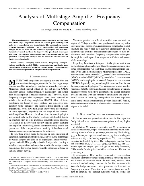
Analysis of Multistage Amplifier–FrequencyCompensationKa Nang Leung and Philip K.T.Mok,Member,IEEEAbstract—Frequency-compensation techniques of single-,two-and three-stage amplifiers based on Miller pole splitting and pole–zero cancellation are reanalyzed.The assumptions made, transfer functions,stability criteria,bandwidths,and important design issues of most of the reported topologies are included. Several proposed methods to improve the published topologies are given.In addition,simulations and experimental results are provided to verify the analysis and to prove the effectiveness of the proposed methods.Index Terms—Damping-factor-control frequency compen-sation,multipath nested Miller compensation,multipath zero cancellation,multistage amplifier,nested Gm-C compensation, nested Miller compensation,simple Miller compensation.I.I NTRODUCTIONM ULTISTAGE amplifiers are urgently needed with the advance in technologies,due to the fact that single-stage cascode amplifier is no longer suitable in low-voltage designs. Moreover,short-channel effect of the sub-micron CMOS transistor causes output-impedance degradation and hence gain of an amplifier is reduced dramatically.Therefore,many frequency-compensation topologies have been reported to stabilize the multistage amplifiers[1]–[26].Most of these topologies are based on pole splitting and pole–zero can-cellation using capacitor and resistor.Both analytical and experimental works have been given to prove the effectiveness of these topologies,especially on two-stage Miller compen-sated amplifiers.However,the discussions in some topologies are focused only on the stability criteria,but detailed design information such as some important assumptions are missing. As a result,if the provided stability criteria cannot stabilize the amplifier successfully,circuit designers usually choose the parameters of the compensation network by trial and error and thus optimum compensation cannot be achieved.In fact,there are not many discussions on the comparison of the existing compensation topologies.Therefore,the differences as well as the pros and cons of the topologies should be inves-tigated in detail.This greatly helps the designers in choosing a suitable compensation technique for a particular design condi-tion such as low-power design,variable output capacitance or variable output current.Manuscript received March9,2000;revised February6,2001.This work was supported by the Research Grant Council of Hong Kong,China under grant HKUST6007/97E.This paper was recommended by Associate Editor N.M.K. Rao.The authors are with the Department of Electrical and Electronic Engineering, The Hong Kong University of Science and Technology,Clear Water Bay,Hong Kong(e-mail:eemok@t.hk).Publisher Item Identifier S1057-7122(01)07716-9.Moreover,practical considerations on the compensation tech-niquesof(a)(b)(c)(d)(e)(f)(g)(h)(i)(j)Fig.1.Studied and proposed frequency-compensation topologies.(a)SMC.(b)SMCNR.(c)MZC.(d)NMC.(e)NMCNR.(f)MNMC.(g)NGCC.(h)NMCF.(i)DFCFC1.(j)DFCFC2.accuracy.In this paper,there are three common assumptionsmade for all studied and proposed topologies.1)The gains of all stages are much greater than one(i.e.,LEUNG et al.:ANALYSIS OF MULTISTAGE AMPLIFIER–FREQUENCY COMPENSATION1043 Assumption1holds true in amplifier designs for most ampli-fiers except those driving small load resistance.If this assump-tion cannot be satisfied,numerical analysis using computers isrequired.Moreover,the parasitic capacitances of the tiny-geom-etry transistors in advanced technologies are small and this val-idates assumptions2)and3).III.R EVIEW ON S INGLE-S TAGE A MPLIFIERThe single-stage amplifier is said to have excellent frequencyresponse and is widely used in many commercial products.Infact,the advantages can be illustrated by its transferfunctiondue to the single pole,assuming thatGBW(i.e.,andminimum.Therefore,a higher bias current and smaller size for all transis-tors in the signal path are required tolocateand the RHP zeroislocates beforepp pp ppz ppp p1044IEEE TRANSACTIONS ON CIRCUITS AND SYSTEMS—I:FUNDAMENTAL THEORY AND APPLICATIONS,VOL.48,NO.9,SEPTEMBER2001Fig.3.PM versus g=gof a SMC amplifier.From (6)and Fig.3,the PM of a SMC amplifier strongly de-pends ontheto ratio and this,in fact,shows the RHP zero effect on the PM.Physically,the presence of the RHP zero is due to the feedforward small-signal current flowing throughthe compensation capacitor to the output [1]–[11].Ifis large,the small-signal output current is larger than the feed-forward current and the effect of the RHP zero appears only at very high frequencies.Thus,asmallis preferable.However,is limited bythe bias current and size of the input differential pair.To have a good slew rate,the bias current cannot be small.In addition,to have a small offset voltage,the size of input differential pair cannot be too small.Emitter/source degeneration technique isalso not feasible toreducesince it reduces the limited input common-mode range in low-voltage design.Therefore,asmallcannot be obtained easily.From the previous analysis,it is known that the RHP zero degrades the stability significantly.There are many methods to eliminate the RHP zero and improve the bandwidth.The methods involve using voltage buffer [4]–[6]and current buffer [7],[8],a nulling resistor [2],[3],[9]–[11],and MZC technique [12].In this paper,the techniques to be discussed are:1)SMC using nulling resistor (SMCNR)and 2)SMC using MZC.A.SMCNRThe presence of the RHP zero is due to the feedforward small-signal current.One method for reducing the feedforward current and thus eliminating the RHP zero is to increase the impedance of the capacitive path.This can be done by inserting a resistor,called nulling resistor,in series with the compensation capacitor,as shown in Fig.1(b).Most published analyses only focus on the effect of the nulling resistor to the position of the zero but not to the positions of the poles.In fact,when the nulling resistor isincreased to infinity,the compensation network is open-circuit and no pole splitting takes place.Thus,the target of this section is to investigate the limit of the nulling resistor.The transfer function of the SMNCR(,,respectively.It is well-known thatwhenis generally much smallerthananddue to theabsence of the RHP zero.However,many designers prefer to use a nulling resistor withvalue largerthansince an accurate valueofandis not a con-stant and a precise cancellation of the RHP zero by afixed)to cancel the feedforward small-signal current(,,which is independentof.(7)LEUNG et al.:ANALYSIS OF MULTISTAGE AMPLIFIER–FREQUENCY COMPENSATION1045 Moreover,since MZC does not change the positions of thepoles,the same dimension condition ofwhich is obtained by neglecting the RHP zerophase shifting term in(6).Besides,when the output current isincreased,is increased accordingly.The nondominant pole()will move to a higher frequency and a largerPM is obtained.Thus,this compensation topology can stabilizethe amplifier within the quiescent to maximum loading currentrange.In some applications,whereand the PM is about90andand.Apparently,the GBW can be increased to infinity bydecreasingto validate the assumptions on deriving(8),so the fol-lowing condition is required as a compromise:,the transfer function is rewritten as(11),shownat the bottom of the page.The dominant pole is1046IEEE TRANSACTIONS ON CIRCUITS AND SYSTEMS—I:FUNDAMENTAL THEORY AND APPLICATIONS,VOL.48,NO.9,SEPTEMBER2001Fig.5.Equivalent small-signal model of three-stage NMC.From the above equation,GBW.Assuming,and are fixed for a given power consumption,largeand are required.This increases the PM but itreduces the GBW and also increases the capacitor values andthe required chip area simultaneously.For the complex-pole approach,the NMC amplifier in unity-feedback configuration should have the third-order Butterworthfrequency response.Let be the closed-loop transferfunctionandshould be in the followingformat:and areobtained:(or)and the damping factor of the complexpoleis(17)which is one-fourth the bandwidth of a single-stage amplifier.This shows the bandwidth reduction effect of nesting compen-sation.Similar to SMC,the GBW can be improved by alargerand asmaller and asmaller.The PM under the effect of a complex pole[28]is givenbyPM(18)Comparing the required compensation capacitors,the GBWand PM under the same power consumption(i.e.,same,and)of the two approaches,it is concluded that thecomplex-pole approach is better.Moreover,from(15)and(16),smallerand are neededwhen.This validates the previous assumption on neglecting the zerossince the coefficients of the function of zero in(10)are smalland the zeros locate at high frequencies.From another pointof view,therequiredand are small,so the feedfor-ward small-signal current can pass to the output only at veryhigh frequencies.In addition,the output small-signal current ismuch larger than the feedforward currentas.Thus,the zeros give negligible effect to the stability.If theseparate-pole approach is applied,the stability is doubtful sincelarger compensation capacitors are required and this generateszeros close to the unity-gain frequency of the amplifier.To further provethat is necessary inNMC,a HSPICE simulation using the equivalent small-signalmodel of NMC,which is shown in Fig.5,is performed.The cir-cuit parametersare A/V,A/V,is satisfied)and10pF.and,which is set according to(15)and(16),are4pFand1pF,respectively.The simulation result is shown in Fig.6by the solid line.A GBW of4.2MHz and a PM of58from100is notmuch largerthan),therequired is changed from4pFto40pF,according to(15).The frequency response is shownby the dotted line in Fig.6.A RHP zero appears before theunity-gain frequency and causes the magnitude plot to curveupwards.The PM is degraded to30ischanged from50is not much largerthan)and is changed from1pF to20pF accordingto(16).As shown by the dashed line in Fig.6,a frequencypeak,due to small damping factor of the complex pole,appearsand makes the amplifier unstable.The phenomenon can be ex-plained from(10).When is not much largerthan,theterm()of the second-order function in the denomi-nator is small and this causes the complex poles to have a smallLEUNG et al.:ANALYSIS OF MULTISTAGE AMPLIFIER–FREQUENCY COMPENSATION1047Fig.6.HSPICE simulation of NMC (solid:g g and g ;dotted:g is not much larger than g ;dash:g is not much larger than g ).damping factor.Ifis very important and critical to the stability of an NMCamplifier.However,this condition is very difficult to achieve,especially in low-power design.Ifdoes not hold true,the analysis should be re-started from (10).Fromthis equation,sincetheterm is negative,there are one RHP zero and one LHP zero.The RHP zero locates at a lower fre-quency astheand only a LHPzeroand any value closedto is able to locate the RHP zero to a high frequency.Bydefining,the transfer function is rewritten as (20)shownat the bottom of the page.It is notedthatand are obtained as in NMC usingcomplex-pole approach and are givenby(i.e.,1048IEEE TRANSACTIONS ON CIRCUITS AND SYSTEMS—I:FUNDAMENTAL THEORY AND APPLICATIONS,VOL.48,NO.9,SEPTEMBER2001Fig.7.Circuit diagram of the amplifiers(a)NMCNR.(b)NMCF.(c)DFCFC1.(d)DFCFC2.).The GBW is given byGBWdue to the LHP zero.A larger GBW can be obtained byslightly reducing but this reduces the PM.To prove the proposed structure,NMC and NMCNR am-plifiers were implemented in AMS10.8.The circuit diagram of the NMCNR amplifiersare shown in Fig.7(a)and the NMC counterpart has the samecircuitry without the nulling resistor.The chip micrograph isshown in Fig.8.Both amplifiers drive a100pF//25knulling resistor,which is made of poly,is used in the NMCNRamplifier.In NMC,the required is99pF,but inNMCNR is63pF.As presented before,the PM of NMCNRamplifier is larger,so a smaller is used in the implemen-tation to obtain a similar PM as in NMC and a larger GBW.Moreover,this greatly reduces the chip area from0.23mm.The measured results and improvement comparison are tabu-lated in Tables I and II,respectively.Both amplifiers haveW power consumption and)are improvedby+39%,+3is improvedLEUNG et al.:ANALYSIS OF MULTISTAGE AMPLIFIER–FREQUENCY COMPENSATION 1049TABLE IM EASURED R ESULTS OF THE AMPLIFIERSTABLE III MPROVEMENT OF THE P ROPOSED AND P UBLISHED T OPOLOGIES W ITH NMC (,and the chip area.VI.MNMCBesides increasing the power,the multipath technique can be used to increase the bandwidth of an amplifier.In MNMC[12],[16],[19],and [26],a feedforward transconductance stage (FTS)is added to the NMC structure to create a low-fre-quency LHP zero.This zero,called multipath zero,cancels the second nondominant pole to extend the bandwidth.The structure of MNMC is shown in Fig.1(f)and it is limited to three-stage amplifiers but it has potential to extend to more stages.However,power consumption and circuit complexity are increased accordingly since a feedforward input differ-ential stage,as same as MZC,is needed,so this will not be discussed here.The input of the FTS,withtransconductanceand the output is connected to the input of theoutput stage.Again,with the conditionthat,the transfer function is given by (23)at the bottom of the next page.The nondominant poles are givenby1050IEEE TRANSACTIONS ON CIRCUITS AND SYSTEMS—I:FUNDAMENTAL THEORY AND APPLICATIONS,VOL.48,NO.9,SEPTEMBER2001Fig.9.Simulation results of an MNMC amplifier using equivalent small-signal circuit under the change of g andC =20pF;dash:g =10mA/V andC =1pF)..The explicit dimensionconditionofis,therefore,givenbyin MNMC is much larger thanthat in NMC.This increases the required chip area and reduces the SR dramatically.Therefore,emitter degeneration technique was used in the design of [16].This can reduce theeffective so thatthe is,as a result,smaller.With (24),the positionsofis thefollowing:.The above analysis gives the required valuesof,and,,and.In fact,if this assumption does nothold true,the positions of the poles and the LHP zero are not those previously stated.Moreover,a RHP zero exists and the stability is greatly affected.The analysis and dimension conditions are obtained in static state.Since there is a pole–zero doublet before the unity-gain frequency,the dynamic-state stability should also be consid-ered.Since,in practice,the loading current andcapacitancemay change in some general-purpose amplifiers with Class-AB output stage,it is necessary to consider the stability of theMNMC amplifierwhenis increasedand ,where the ratio isobtained from (24)and (26).Besides,the multipath zero is notchangedwhenand with the condition in (27).It is obviousthat,so MNMC is not affected by changing the loading current and capacitance.To prove the above arguments,a simulation using HSPICE is performed with the equivalent small-signal circuit of an MNMCamplifier.The circuit parametersareA/V,,1M25k 20p F.T h u s,111.25i s c h a n g e d f r o m 1m A /V t o 10m A /V ;a n d 2)a nd i s i n c re a s e d or a r e r e q u i r e d .T h i s c o n d i t i o n n o t o n l y i m -p r o v e s t h e s t a b i l i t y b u t i t a l s o s i m p l i f i e s t h e t r a n s f e r f u n c t i o n .I n f a c t ,a s m e n t i o n e d b e f o r e ,t h i s c o n d i t i o n i s d i f f i c u l t t o a c h i e v e i n l o w -p o w e r d e s i g n ,s o Y o u e t a l .i n t r o d u c e d N G C C [20].N G C C i s a n-s t a g e N G C Ca m p l i f i e r.W i t h t h e c o n d i t i o n t h at w e re ,t h e g e n e r a lf o r m o f a n-s t a g e a m p l i f i e r t h a n N M C .I n t h e s t a b i l i t y c o n d i t i o n s p r o p o s e d b y Y o u e t a l .,t h e s e p a r a t e d -p o l e a p p r o a c h i s u s e d a n d t h e n o n d o m a r e s e t t o s o m e f r e q u e n c i e s s u c h t h a t t h e G B W ,T s a nd p o we r c o n s u m p t i o n a r e a l l o p t i m i z e d .U n d o u b t e d l y ,t h c a t e d t o d o o p t i m i z a t i o n a n a l y t i c a l l y ,s o n u m e u s i n g M A T L A B i s r e q u i r e d .H o w e v e r ,q u e s t i o n s o n p r a c t i c a l c o n s i d e r a t i o n s ,s i n c e i t i s p r ef e r a m i n i m u m s t ag e s a s p o s s i b l e .A s s t a t e d b e f o r e ,t a n o p t i m u m n u m b e r o n d c g a i n ,b a n d w i d th ,a n d s u m p ti o n .T h e r e f o r e ,t h e a n a l y s i s i n t h i s s e c t i o n t h e t h r e e -s t a g e N G C C a m p l i f i e r.T h e s t r u c t u r e oN G C C a m p l i f i e r i s s h o w n i n F i g .1(g )a n d t h e t r a ni s g i v e n b y (29)s h o w n a t t h e b o t t o m o f t h e p a g eb e f o r e a n d a l s o f r o m t h e n u m e r a t o r o f (29),t h e b e e l i m i n a t e d b y s e t t i n g a nd .T h et r a n s f e r f u n c t i o n i s t h e n s i m p l i f i e d t o (30)s h o wo f t h e p a g e .T h e a r r a n g e m e n t o f t h e p o l e s c a n u ss e p a r a t e -p o l e o r c o m p l e x -p o l e a p p r o a c h b u t t h ep r e f e r r e d .I t i s o b v i o u s t h a t t h e d e n o m i n a t o r o s a m e a s (11)b u t t h e d i f f e r e n c e i s t h a t i s n o t r e q u i r e d i n N G C C .T h u s,.A l t h o u g h N G C C i s g o o d i n l o w -p o w e r d e s i g n s ,s t a g e F T S (i .e .,some of them are LHP zeros which,in fact,help to increase the PM.With regard to the above considerations,a new structure, called NMC with feedforward Gm stage(NMCF),is proposed and shown in Fig.1(h).There are only two differences betweenNMCF and NGCC:1)the input-stage FTS is removed and2).Bydefiningand are obtained using thecomplex-pole approach and they are givenby,are smaller than those in NMC,MNMC and NGCCsinceterm is positive andthe term is negative,the LHPzerolocates before the RHPzerofor stability purpose,so the following condition isrequired:(34)The condition states the minimum valueof to obtain anoptimum control of LHP zero.From(31)to(33),the GBW and PM are given byGBW(35)andPM(36)It is shown in(35)that the bandwidth is improved by the pres-enceofmCMOS process was done to prove the proposed structure.TheNMCF amplifier is shown in Fig.7(b)and it is basically thesame as the NMC amplifier.It is noted that the gate of M32,which is the FTS,is connected to the output of the first stage.The output stage is of push-pull typeand,from(35),to double the GBW.The measured results and improvement comparison areshown in Tables I and II,respectively.It is obvious that theimprovement of NMCF over NMC on GBW(),PM()and occupied chip area()are much larger than those in MNMC and NGCCin other designs,which are shown in Table II.The powerconsumption is only increased by6and inverselyproportionaltois removed and the bandwidth of the ampli-fier can be extended substantially.However,the damping factorof the nondominant complex poles,which is originally con-trolledby,cannot be controlled and a frequency peak,which causes the closed-loop amplifier to be unstable,appearsin the magnitude Bode plot[23].To control the damping factorand make the amplifier stable,a damping-factor-control(DFC)block is added.The DFC block is basically a gain stage withdc gain greater than one(i.e.,.The DFC block functions as a frequency-de-pendent capacitor and the amount of the small-signal currentinjected into the DFC block depends on the valueofand(transconductance of the gain stage inside the DFC block).Hence,the damping factor of the nondominant complex polescan be controlled byoptimumand and this makesthe amplifier stable.There are two possible positions to add theDFC block and they are shown in Fig.1(i)for DFCFC1andFig.1(j)for DFCFC2.In addition,both structures have a feed-forward transconductance stage to form a push-pull output stagefor improving large-signal slewing performance.For DFCFC1,the transfer function is given by(37)shown atthe bottom of the next page.It can be seen from(37)that thedamping factor of the nondominant poles can be controlledby.Moreover,the effectofandtransfer functionbut is limitedto tovalidate (37).Sinceis small,the amplifier is not slowed downby.From (37),there are three poles,so the com-plex-pole approach is used.Moreover,since it is preferable to have the same output current capability for boththe -transistor of the output stage,the sizes ofthe -tran-sistor are used in ratio of 3to 1to compensate for the differ-ence in the mobilities of the carriers.Thus,it is reasonable toset,so the dimension conditions are givenby (39)whereis much smaller thanthat in the previous nesting topologies,so the SR is also greatly improved,assuming that the SR is not limited by the outputstage.Moreover,is a decreasing functionof (41)and the PM is about 60times.Ifa little,butthis reduces the PM as a tradeoff.For DFCFC2,bysettingwith the same reason stated previously,the transfer function is given by (42)shown at the bottom of the page.Similar to DFCFC1,the complex-poleapproach is used to achieve the stability.Therefore,the dimen-sion conditions are givenby(43)is a fixed value and is four timesof.Thus,the power consumption of DFCFC2amplifier with certain valueof.Although it is difficult to comparethe GBW of DFCFC2with other topologies since the format is different,it is in general better than others.It is due to the fact that the GBW is inversely proportion to the geometric meanof,which gives a smaller valuethan mdouble-metal double-poly CMOS process.The circuit diagrams are shown in Fig.7(c)for DFCFC1and Fig.7(d)for DFCFC2.The micrograph is,again,shown in Fig.8.In both amplifiers,M41andform the DFC block and M32is the FTS.Moreover,from Table II,the GBW,PM,SR,TIX.S UMMARY OF S TUDIED F REQUENCY C OMPENSATIONT OPOLOGIESA summary on the required stability conditions,resultant GBW and PM for all studied and proposed topologies are given in Table parisons on the topologies are tabulated in Table IV.Moreover,some important points derived from the previous analyzes are summarized as follows.1)The stability-dimension conditions of all topologies arebased on the assumptions stated in Section II.If the as-sumptions cannot be met,numerical method should be used to stabilize the amplifiers.2)With the exception of the single-stage amplifier,alargerandlargestandreducingto ratio and asmallerto ratio.6)For high-speed applications,a larger bias current shouldbe applied to the output stage toincrease.Fig.10.Local feedback circuitry to control the dc operating point of the DFCblock.X.R OBUSTNESS OF THE S TUDIED F REQUENCY C OMPENSATION In IC technologies,the circuit parameters such as transcon-ductance,capacitance and resistance vary from run to run,lot to lot and also according to temperature.The robustness of fre-quency compensation is very important to ensure the stabilities of multistage amplifiers.From the summary in Table III,the required values of com-pensation capacitors depend on the ratio of transconductances of gain stages explicitly for SMC,SMCNR,MZC1,MZC2,NMC,NMCNR,MNMC,NGCC,NMCF,and DFCFC1and implicitly for DFCFC2.The ratio maintains constant for any process varia-tion and temperature effect with good bias current matching and transistor size matching (due to design).One important point is that the valueof50%,in general is not significantto the stability.In MNMC,pole–zero cancellation is used.However,the su-perior tracking technique in MNMC is due to the pole–zero can-cellation based on the ratios of transconductances and compen-sation capacitances.Thus,process variations do not affect the compression of the pole–zero doublet.Although the robustness of the studied topologies are good,the exact value of the GBW will be affected by process varia-tions.Referring to Table III,the GBW’s of all topologies,in-cluding commonly used single-stage and Miller-compensated amplifiers,depend on the transconductance of the output stage.Thus,the GBW will change under the effect of process varia-tions and temperature.XI.C ONCLUSIONSeveral frequency-compensation topologies have been investigated analytically.The pros and cons as well as the design requirements are discussed.To improve NMC and NGCC,NMCNR,and NMCF are proposed and the improved performance is verified by experimental results.In addition,DFCFC has been introduced and it has much better frequency and transient performances than the other published topologies for driving large capacitive loads.Finally,robustness of the studied topologies has been discussed.R EFERENCES[1]J.E.Solomon,“The monolithic op amp:A tutorial study,”IEEE J.Solid-State Circuits ,vol.9,pp.314–332,Dec.1974.[2]P.R.Gray and R.G.Meyer,Analysis and Design of Analog IntegratedCircuits ,2ed.New York:Wiley,1984.[3]W.-H.Ki,L.Der,and m,“Re-examination of pole splitting of ageneric single stage amplifier,”IEEE Trans.Circuits Syst.I ,vol.44,pp.70–74,Jan.1997.[4]Y.P.Tsividis and P.R.Gray,“An integrated NMOS operational amplifierwith internal compensation,”IEEE J.Solid-State Circuits,vol.SC-11, pp.748–753,Dec.1976.[5]G.Smarandoiu,D.A.Hodges,P.R.Gray,and ndsburg,“CMOSpulse-code-modulation voice codec,”IEEE J.Solid-State Circuits,vol.SC-13,pp.504–510,Aug.1978.[6]G.Palmisano and G.Palumbo,“An optimized compensation strategyfor two-stage CMOS OP AMPS,”IEEE Trans.Circuits Syst.I,vol.42, pp.178–182,Mar.1995.[7] B.K.Ahuja,“An improved frequency compensation technique forCMOS operational amplifiers,”IEEE J.Solid-State Circuits,vol.SC-18,no.6,pp.629–633,Dec.1983.[8]G.Palmisano and G.Palumbo,“A compensation strategy for two-stageCMOS opamps based on current buffer,”IEEE Trans.Circuits Syst.I, vol.44,pp.257–262,Mar.1997.[9] D.Senderowicz,D.A.Hodges,and P.R.Gray,“High-performanceNMOS operational amplifier,”IEEE J.Solid-State Circuits,vol.SC-13, pp.760–766,Dec.1978.[10]W.C.Black Jr,D.J.Allstot,and R.A.Reed,“A high performance lowpower CMOS channel filter,”IEEE J.Solid-State Circuits,vol.15,pp.929–938,Dec.1980.[11]P.R.Gray and R.G.Meyer,“MOS operational amplifier design—a tu-torial overview,”IEEE J.Solid-State Circuits,vol.SC-17,pp.969–982, Dec.1982.[12]R.G.H.Eschauzier and J.H.Huijsing,Frequency Compensation Tech-niques for Low-Power Operational Amplifiers.Boston,MA:Kluwer, 1995.[13] E.M.Cherry,“A new result in negative feedback theory and its applica-tions to audio power amplifier,”Int.J.Circuit Theory Appl.,vol.6,no.3,pp.265–288,1978.[14],“Feedback systems,”U.S.Patent4243943,Jan.1981.[15] F.N.L.Op’t Eynde,P.F.M.Ampe,L.Verdeyen,and W.M.C.Sansen,“A CMOS large-swing low-distortion three-stage class AB power am-plifier,”IEEE J.Solid-State Circuits,vol.25,pp.265–273,Feb.1990.[16]R.G.H.Eschauzier,L.P.T.Kerklaan,and J.H.Huijsing,“A100MHz100dB operational amplifier with multipath nested miller compensation structure,”IEEE J.Solid-State Circuits,vol.27,pp.1709–1717,Dec.1992.[17] E.M.Cherry,“Comment on a100MHz100dB operational amplifierwith multipath nested miller compensation structure,”IEEE J.Solid-State Circuits,vol.31,pp.753–754,May1996.[18]S.Pernici,G.Nicollini,and R.Castello,“A CMOS low-distortion fullydifferential power amplifier with double nested Miller compensation,”IEEE J.Solid-State Circuits,vol.28,pp.758–763,July1993.[19]K.-J.de Langen,R.G.H.Eschauzier,G.J.A.van Dijk,and J.H.Hui-jsing,“A1GHz bipolar class-AB operational amplifier with multipath nested Miller compensation for76dB gain,”IEEE J.Solid-State Cir-cuits,vol.32,pp.488–498,Apr.1997.[20] F.You,S.H.K.Embabi,and E.Sánchez-Sinencio,“Multistage ampli-fier topologies with nested gm-C compensation,”IEEE J.Solid-State Circuits,vol.32,pp.2000–2011,Dec.1997.[21]H.-T.Ng,R.M.Ziazadeh,and D.J.Allstot,“A mulitstage amplifiertechnique with embedded frequency compensation,”IEEE J.Solid-State Circuits,vol.34,pp.339–341,Mar.1999.[22]K.N.Leung,P.K.T.Mok,W.H.Ki,and J.K.O.Sin,“Damping-factor-control frequency compensation technique for low-voltage low-power large capacitive load applications,”in Dig.Tech.Papers ISSCC’99,1999, pp.158–159.[23],“Three-stage large capacitive load amplifier with damping-factor-control frequency compensation,”IEEE J.Solid-State Circuits,vol.35, pp.221–230,Feb.2000.[24],“Analysis on alternative structure of damping-factor-control fre-quency compensation,”in Proc.IEEE ISCAS’00,vol.II,May2000,pp.545–548.[25]K.N.Leung,P.K.T.Mok,and W.H.Ki,“Right-half-plane zero re-moval technique for low-voltage low-power nested miller compensation CMOS amplifiers,”in Proc.ICECS’99,vol.II,1999,pp.599–602. [26]J.H.Huijsing,R.Hogervorst,and K.-J.de Langen,“Low-power low-voltage VLSI operational amplifier cells,”IEEE Trans.Circuits Syst.I, vol.42,pp.841–852,Nov.1995.[27]G.C.Temes and Patra,Introduction to Circuit Synthesis andDesign,1ed.New York:McGraw-Hill,1977.[28]J.W.Nilsson,Electric Circuits,4ed.New York:Addison Wesley,1993.[29] B.Y.Kamath,R.G.Meyer,and P.R.Gray,“Relationship between fre-quency response and settling time of operational amplifier,”IEEE J.Solid-State Circuits,vol.SC-9,pp.247–352,Dec.1974.[30] C.T.Chuang,“Analysis of the settling behavior of an operational am-plifier,”IEEE J.Solid-State Circuits,vol.SC-17,pp.74–80,Feb.1982. Ka Nang Leung received the B.Eng.and M.Phil.degrees in electronic engi-neering from the Hong Kong University of Science and Technology(HKUST), Clear Water Bay,Hong Kong,in1996and1998,respectively.He is now working toward the Ph.D.degree in the same department.During the B.Eng.studies,he joined Motorola,Hong Kong,to develop a PDA system as his final year project.In addition,he has developed several frequency-compensation topologies for multistage amplifiers and low dropout regulators in his M.Phil studies.He was a Teaching Assistant in courses on analogue integrated circuits and CMOS VLSI design.His research interests are low-voltage low-power analog designs on low-dropout regulators,bandgap voltage references and CMOS voltage references.In addition,he is interested in developing frequency-compensation topologies for multistage amplifiers and for linear regulators.In1996,he received the Best Teaching Assistant Award from the Department of Electrical and Electronic Engineering at theHKUST.Philip K.T.Mok(S’86–M’95)received theB.A.Sc.,M.A.Sc.,and Ph.D.degrees in electricaland computer engineering from the University ofToronto,Toronto,Canada,in1986,1989,and1995,respectively.From1986to1992,he was a Teaching Assistant,at the University of Toronto,in the electrical engi-neering and industrial engineering departments,andtaught courses in circuit theory,IC engineering andengineering economics.He was also a Research As-sistant in the Integrated Circuit Laboratory at the Uni-versity of Toronto,from1992to1994.He joined the Department of Electrical and Electronic Engineering,the Hong Kong University of Science and Tech-nology,Hong Kong,in January1995as an Assistant Professor.His research interests include semiconductor devices,processing technologies and circuit de-signs for power electronics and telecommunications applications,with current emphasis on power-integrated circuits,low-voltage analog integrated circuits and RF integrated circuits design.Dr.Mok received the Henry G.Acres Medal,the W.S.Wilson Medal and Teaching Assistant Award from the University of Toronto and the Teaching Ex-cellence Appreciation Award twice from the Hong Kong University of Science and Technology.。
Sigmund_99行拓扑优化程序

%%%% A 99 LINE TOPOLOGY OPTIMIZATION CODE BY OLE SIGMUND, JANUARY 2000 %%%%%%% CODE MODIFIED FOR INCREASED SPEED, September 2002, BY OLE SIGMUND %%%function top(nelx,nely,volfrac,penal,rmin);nelx=80;nely=20;volfrac=0.4;penal=3;rmin=2;% INITIALIZEx(1:nely,1:nelx) = volfrac;loop = 0;change = 1.;% START ITERA TIONwhile change > 0.01loop = loop + 1;xold = x;% FE-ANAL YSIS[U]=FE(nelx,nely,x,penal);% OBJECTIVE FUNCTION AND SENSITIVITY ANAL YSIS[KE] = lk;c = 0.;for ely = 1:nelyfor elx = 1:nelxn1 = (nely+1)*(elx-1)+ely;n2 = (nely+1)* elx +ely;Ue = U([2*n1-1;2*n1; 2*n2-1;2*n2; 2*n2+1;2*n2+2; 2*n1+1;2*n1+2],1);c = c + x(ely,elx)^penal*Ue'*KE*Ue;dc(ely,elx) = -penal*x(ely,elx)^(penal-1)*Ue'*KE*Ue;endend% FILTERING OF SENSITIVITIES[dc] = check(nelx,nely,rmin,x,dc);% DESIGN UPDA TE BY THE OPTIMALITY CRITERIA METHOD[x] = OC(nelx,nely,x,volfrac,dc);% PRINT RESULTSchange = max(max(abs(x-xold)));disp([' It.: ' sprintf('%4i',loop) ' Obj.: ' sprintf('%10.4f',c) ...' Vol.: ' sprintf('%6.3f',sum(sum(x))/(nelx*nely)) ...' ch.: ' sprintf('%6.3f',change )])% PLOT DENSITIEScolormap(gray); imagesc(-x); axis equal; axis tight; axis off;pause(1e-6);end%%%%%%%%%% OPTIMALITY CRITERIAUPDATE %%%%%%%%%%%%%%%%%%%%%%%%%%%%%%%%%%%%%% function [xnew]=OC(nelx,nely,x,volfrac,dc)l1 = 0; l2 = 100000; move = 0.2;while (l2-l1 > 1e-4)lmid = 0.5*(l2+l1);xnew = max(0.001,max(x-move,min(1.,min(x+move,x.*sqrt(-dc./lmid)))));if sum(sum(xnew)) - volfrac*nelx*nely > 0;l1 = lmid;elsel2 = lmid;endend%%%%%%%%%% MESH-INDEPENDENCYFILTER %%%%%%%%%%%%%%%%%%%%%%%%%%%%%%%%%%%%%%%% function [dcn]=check(nelx,nely,rmin,x,dc)dcn=zeros(nely,nelx);for i = 1:nelxfor j = 1:nelysum=0.0;for k = max(i-floor(rmin),1):min(i+floor(rmin),nelx)for l = max(j-floor(rmin),1):min(j+floor(rmin),nely)fac = rmin-sqrt((i-k)^2+(j-l)^2);sum = sum+max(0,fac);dcn(j,i) = dcn(j,i) + max(0,fac)*x(l,k)*dc(l,k);endenddcn(j,i) = dcn(j,i)/(x(j,i)*sum);endend%%%%%%%%%%FE-ANAL YSIS %%%%%%%%%%%%%%%%%%%%%%%%%%%%%%%%%%%%%%% %%%%%%%%%%%%%%function [U]=FE(nelx,nely,x,penal)[KE] = lk;K = sparse(2*(nelx+1)*(nely+1), 2*(nelx+1)*(nely+1));F = sparse(2*(nely+1)*(nelx+1),1); U = zeros(2*(nely+1)*(nelx+1),1);for elx = 1:nelxfor ely = 1:nelyn1 = (nely+1)*(elx-1)+ely;n2 = (nely+1)* elx +ely;edof = [2*n1-1; 2*n1; 2*n2-1; 2*n2; 2*n2+1; 2*n2+2; 2*n1+1; 2*n1+2];K(edof,edof) = K(edof,edof) + x(ely,elx)^penal*KE;endend% DEFINE LOADS AND SUPPORTS (HALF MBB-BEAM)F(2*(nelx/2+1)*(nely+1),1) = 1;fixeddofs = [2*(nely/2+1),2*nelx*(nely+1)+2*(nely/2+1)];alldofs = [1:2*(nely+1)*(nelx+1)];freedofs = setdiff(alldofs,fixeddofs);% SOLVINGU(freedofs,:) = K(freedofs,freedofs) \ F(freedofs,:);U(fixeddofs,:)= 0;%%%%%%%%%% ELEMENT STIFFNESSMATRIX %%%%%%%%%%%%%%%%%%%%%%%%%%%%%%%%%%%%%%%% function [KE]=lkE = 1.;nu = 0.3;k=[ 1/2-nu/6 1/8+nu/8 -1/4-nu/12 -1/8+3*nu/8 ...-1/4+nu/12 -1/8-nu/8 nu/6 1/8-3*nu/8];KE = E/(1-nu^2)*[ k(1) k(2) k(3) k(4) k(5) k(6) k(7) k(8)k(2) k(1) k(8) k(7) k(6) k(5) k(4) k(3)k(3) k(8) k(1) k(6) k(7) k(4) k(5) k(2)k(4) k(7) k(6) k(1) k(8) k(3) k(2) k(5)k(5) k(6) k(7) k(8) k(1) k(2) k(3) k(4)k(6) k(5) k(4) k(3) k(2) k(1) k(8) k(7)k(7) k(4) k(5) k(2) k(3) k(8) k(1) k(6)k(8) k(3) k(2) k(5) k(4) k(7) k(6) k(1)];%%%%%%%%%%%%%%%%%%%%%%%%%%%%%%%%%%%%%%%%%%%%%% %%%%%%%%%%%%%%%%%%%%%%%%%%%%%%%。
最优变重量光正交码的构造

: r移动频率 、 调频扩 频通信 、 雷达 、 声纳 、 无反馈 碰撞 信道 和 神经 网络 中_ ] 一 来说 _ 。 般 3 。 码字 的个 数依赣 于 码字 的重 , 变重量 光 I交 码可 以得 到 比常 重量光 j 交 码更多 的码字 个数 。1 9 年 , a g在 文献[ ] E E 96 Y n 9 中
引 入变重量 光正交 码 , 用于 多媒体 光 C DMA 系统 以满 足不同服 务质量 用户 的需求 。 最近 , 变重量 光正交 码 己引起 r人 们广泛 的研究兴 趣 ¨ 。 ]
一
本文 采 用文献 E ] g 中的记 号 , 令 、 Q分别 表示集 合{ ' 一, } { , , , } {og “ q } L、 / U 叫 , … ,g . , 。 个( , , 变重 世光 正交 码 c, ( , , 一 C 是一 族长 度 为 的 ( , ) , L, Q) 或 , , Q) OO 0 】 序列 ( 码字 ) 满 ,
第 4期
韦 月 尔等 : 优 变 重 量 光 正 交 码 的构 造 最
5 9
引 1 ( , )m{q { j o ≤} 中 ( , )m (I 理 l 1  ̄il, ¨ , n l Q k Jq: 户其 1 一aI: / ≤ , , , xC Q
C 是 一个 ( W , , 一 , 1Q)OOC} 。
一
个 , , , 一 1 Q)OOC称 为最优 的 , O( , , , 达到 引理 1中 的上界 。 n 若 v W 1Q) Ya g在文 献 [ ] 9 中给 出了
摘
要: 变
光 正 交 码 啊于 光 码 分 多 址 通 信 系 统 以 满 足 不 同 服 务 质 量 用 户需 求 。本 文 证 明 r当 q 3 ro 一 ( d o
Spotlight SAR data focusing based on a two-step processing approach
Spotlight SAR Data Focusing Based on a Two-StepProcessing ApproachRiccardo Lanari,Senior Member,IEEE,Manlio Tesauro,Eugenio Sansosti,Member,IEEE,and Gianfranco FornaroAbstract—We present a new spotlight SAR data-focusing algo-rithm based on a two-step processing strategy that combines the advantages of two commonly adopted processing approaches:the efficiency of SPECAN algorithms and the precision of stripmap fo-cusing techniques.The first step of the proposed algorithm imple-ments a linear and space-invariant azimuth filtering that is carried out via a deramping-based technique representing a simplified ver-sion of the SPECAN approach.This operation allows us to perform a bulk azimuth raw data compression and to achieve a pixel spacing smaller than(or equal to)the expected azimuth resolution of the fully focused image.Thus,the azimuth spectral folding phenom-enon,typically affecting the spotlight data,is overcome,and the space-variant characteristics of the stripmap system transfer func-tion are preserved.Accordingly,the residual and precise focusing of the SAR data is achieved by applying a conventional stripmap processing procedure requiring a minor modification and imple-mented in the frequency domain.The extension of the proposed technique to the case of high bandwidth transmitted chirp signals is also discussed.Experiments carried out on real and simulated data confirm the validity of the presented approach,which is mainly focused on spaceborne systems.Index Terms—Raw data focusing,spectral analysis(SPECAN) processing algorithms.I.I NTRODUCTIONS YNTHETIC aperture radar(SAR)spotlight mode allows the generation of microwave images with high geometric resolutions[1],[2].This result is achieved by steering the radar antenna beam,during the raw data acquisition interval,to al-ways illuminate the same area on the ground(spot).Accord-ingly,from each target located in the lighted area,a large number of backscattered echoes is received,and their coherent combina-tion allows to obtain the required azimuth resolution.Similarly, high resolution in the range direction is achieved by transmitting a high bandwidth chirp followed by a further data processing on each received echo.The first algorithms proposed for spotlight raw data pro-cessing are based on the similarity between spotlight SAR systems and computer tomography:they are usually referredManuscript received March30,2000;revised November29,2000.This work was partially supported by the Italian Space Agency,Roma,Italy.The spotlight SIR-C data have been processed at the Jet Propulsion Laboratory,Pasadena,CA. nari,E.Sansosti,and G.Fornaro are with the Istituto di Ricerca per l’Elettromagnetismo e i Componenti Elettronici(IRECE)328I-80124 Napoli,Italy,(e-mail:lanari@r.it;sansosti@r.it; fornaro@r.it).M.Tesauro is with the Dipartimento di Ingegneria dell’Innovazione,Univer-sitàdegli Studi di Lecce,I-73100Lecce,Italy(e-mail:manlio.tesauro@unile.it). Publisher Item Identifier S0196-2892(01)07625-2.to as polar format and convolution backprojection techniques [3]–[5].The former are computationally efficient but request a nontrivial interpolation step from a polar to rectangular grid: the image quality can be therefore affected by uncompensated range curvature effects[6]and interpolation errors.The latter allow overcoming these limitations but are generally inefficient if implementations on dedicated architectures are not consid-ered[5].Most recently,the development of spotlight raw data processing algorithms based on stripmap mode focusing techniques operating in the frequency domain has received increasing interest[7]–[10].Indeed,strip-mode processing procedures that are precise,efficient,and requiring less stringent approximations(compared to those involved in the tomographic approaches)are available[11]–[13].However,a relevant limitation to the straightforward application of these techniques to the spotlight data processing is represented by the fact that the raw signal azimuth bandwidth is,in the spotlight case,generally greater(often much greater)than the azimuth sampling frequency,referred to as pulse repetition frequency(prf).As a consequence,data processing carried out in the Fourier domain,as that involved in efficient strip-mode focusing,cannot be directly implemented on the full aperture because of the consequential azimuth spectrum folding effect.A way to overcome this limitation is based on partitioning the received signal into azimuth blocks whose block-bandwidths are smaller than the sampling frequency.Standard strip mode focusing techniques are then applied to each data block and the processed signals are then combined to generate the fully-resolved spotlight image[9],[10].Completely different pro-cessing solutions,based on a nontrivial reconstruction of the unfolded azimuth spectrum from the folded one associated to the raw signal,are also available[7],[8].On the other hand,a relatively simple spotlight processing al-gorithm can be implemented by applying the spectral analysis (SPECAN)technique[14].In this case,the received raw data are azimuth focused via the application of a deramping func-tion(a multiplication by a properly chosen chirp signal)fol-lowed by a final azimuth FT operation.The azimuth deramping factor is updated in range to allow for the compensation of the space-varying characteristic of the received data due to the(az-imuth)chirp rate range variation(focus depth).This procedure is attractive as far as computational efficiency and capability to overcome the azimuth spectral folding effect are concerned. However,its main limitation is represented by the lack of a pre-cise range cell migration(RCM)compensation that is often rel-evant in spotlight mode SAR systems due to high resolution re-quirements.0196–2892/01$10.00©2001IEEEIn this paper,we propose an alternative spotlight data fo-cusing technique based on decoupling the overall focusing oper-ation in two main steps.The key point of the proposed approach is to combine the advantages of efficient SPECAN and precise stripmap focusing approaches.In particular,the first processing step carries out a filtering operation aimed to achieve a bulk az-imuth raw data compression and an output pixel spacing smaller than(or equal to)the expected final azimuth resolution.Similar to SPECAN processing algorithms,this filtering operation is ef-ficiently carried out via a deramping-based approach[14]but, at variance of the former,the chirp rate of the deramping func-tion is kept constant and properly fixed at a convenient value. This is a key point in the proposed processing procedure that al-lows preserving the space variant characteristic of the residual system transfer function(STF).A discussion on the impact of the chirp rate selection on possible artifacts that may appear at the image borders is also provided.The second processing step carries out the residual focusing of the data via the use of a conventional stripmap processing pro-cedure implemented in the frequency domain and requiring only minor modifications in the available codes.This spectral do-main focusing operation is now possible because,following the bulk azimuth compression,the folding effect of the raw signal azimuth spectrum has been totally overcome.More precisely, this second(residual)processing step performs the precise RCM compensation,the data range compression and the residual az-imuth data compression;the latter accounts for higher order terms not compensated in the bulk azimuth processing step.The minor modifications to be performed in available stripmap pro-cessing codes are essentially a change of the azimuth filter func-tion,which accounts for the already compensated quadratic az-imuth phase term,and a change in the azimuth pixel spacing of the input data.It is worth noting the role that the bulk azimuth compres-sion operation plays in our approach to a preprocessing step that extends the processing capability of conventional stripmap fo-cusing procedures to spotlight data.In addition,the proposed processing algorithm does not require a specific manipulation and/or interpolation of the data,such as those necessary in az-imuth block divisions or in unfolded signal spectrum reconstruc-tion-based algorithms.Accordingly,we have finally achieved a processing procedure that is simple,precise and computation-ally efficient because it does not imply any significant increase of the raw data matrix dimensions and only includes fast Fourier transforms(FFTs)and matrix multiplication.Moreover,it can be easily extended to the case of high bandwidth transmitted sig-nals wherein spectral folding effects could appear in the range direction as well.In our case,the implemented solution is based again on a deramping approach,that is,at variance of conven-tional focusing techniques performed following the A/D con-version rather than before.A number of experiments carried out on a simulated and a real data set,the latter acquired by the experimental C-band sensor of the SIR-C system during the SIR-C/X-SAR mission in1994[9],demonstrate the validity of the presented approach.As a final remark,we want to stress that the presented anal-ysis is focused on spaceborne systems typically characterized by small squint angles[15]during the acquisition(often lessthan Fig.1.Spotlight system geometry.1-axis,assumed coincident with the platform flight path,is referred to as azimuthdirection are the(closest approach)target range and look angle,respectively.1We assume in the following that the sensor,mounted onboard a platform moving at the constantvelocity,transmits,attimes(1) whereangular carrierfrequency;chirp rate,beingis the systemwavelength,,the two-way antenna pattern factor,and being the azimuth dimension of the real,onboard antenna.Note that the assumed simplificationon allows avoiding the antenna footprint dependence on the platform location whose impact is 1Note that we have assumed the platform trajectory to be a straight line which is appropriate for airborne but not for spaceborne sensors.However,it can be shown that spaceborne data can be processed in the same manner as airborne data if the closed approach distance and the azimuth velocity are properly con-sidered[16]or,more precisely,via the appropriate sensor-target distance eval-uation[17].LANARI et al.:SPOTLIGHT SAR DATA FOCUSING 1995inessential for the following analysis.A more detailed discus-sion on this matter can be found in [10].Let us now consider a pointtargetandreceived onboard is represented,after the heterodyne process [that removes the fast varyingterm(4a)FTis the azimuth (spatial)frequency.Equation (7)shows that theazimuth spectrum is centered on thefrequencyand that the signal bandwidthiswith respect to the strip mode case,for whichit wouldbe.In this case,weget(8)Since the maximum valueof,i.e.,that relative to the nearest range,should be con-sidered.This is assumed hereafter,although we underline that in the spotlight case,due to the typically limited range extension of the illuminated spot,the range dependenceof (9)in order to avoid any azimuth spectral folding effect [18].On the other hand,this sampling frequency increase would lead to large data rates and could generate severe range ambiguity problems [15].Accordingly,the valuesofand are the raw data and thefocused image azimuth pixel dimensions,respectively,the latter chosen in agreement with the Nyquist limit available from (8).In this case,we get from(9)(10)1996IEEE TRANSACTIONS ON GEOSCIENCE AND REMOTE SENSING,VOL.39,NO.9,SEPTEMBER2001 Equation(10)clarifies that the azimuth number of pixel inthe raw data set and in the focused image,i.e.,,respectively,are comparable,and they become closeras.III.B ULK A ZIMUTH R AW D ATA C OMPRESSIONLet us now investigate a possible solution to the azimuth spec-tral folding effect discussed in the previous section.The pro-posed approach is based on a linear and space-invariant azimuthfiltering operation that performs a bulk azimuth data compres-sion and achieves an output pixel spacing,satisfying the Nyquistlimit shown in(8).This operation is efficiently implementedwithout any large zero padding step,via a deramping-basedtechnique[1],[2],[14].A.Continuous Domain AnalysisKey point of the presented technique is the azimuth convolu-tion between the raw data and the quadratic phasesignal(11)whereinand are the nearest and the farthest ranges of theilluminated spot,respectively,and represents the range valueof a generic point target located within the spot.No specific as-sumption has yet been made on the factor in(11),althoughwe anticipate that the impact of any particular selection for thisterm is later discussed in detail.We also underline that the rawsignal range component,accounting for the range independent(RI)and range dependent(RD)RCM effects,is neglected inthe azimuth convolution operation presented in this section.Allthese components are restored and accounted for during the sub-sequent and highly precise second processing step.The azimuth convolution between thesignal in(5),forthe case of an isolated target,and thefunction in(11)gives(12)wherein thesymbolof the target and on the valueof.The second line in(12)shows that this azimuth convo-lution is essentially a deramping based(SPECAN)processing,involving a chirp multiplication of the azimuth signal,a subse-quent FT and a residual phase cancellation.Indeed,but for theabove mentioned approximations,this processing step allows usto achieve an azimuth compression which is full only for thosetargets locatedat.This point can be clarified by recon-sidering(12).Indeed,if weassume(13)wherein the imaged target is fully azimuth focused.Forany,by assuming the validity of theSPM method3weget,for which the resulting signal is centeredaround andextendsfor.However,because the range ex-tension of the spot area is typically very small,we canassumeand,even in this limiting case,a compression effect,althoughpartial with respect to that achieved in(13),is obtained.The obtained results apply to the case of an isolated target,however they can be easily extended to the case of an illumi-nated area.Accounting for the azimuth spotdimensionwith(16)3Generalization to those cases where SPM cannot be applied can be derivedas in[19].Here we are interested only in having a rough measure of the targetecho extension following the first processing step.LANARI et al.:SPOTLIGHT SAR DATA FOCUSING 1997with ,i.e.,with a pixel spacing satisfying the Nyquist limit of the spotlight signal,see (8)and (9).Accordingly,sim-ilarly to what is shown in the continuous analysis presented in the previous section,(12)becomesbeing the nearest integer operator.Note that,dueto(10),with (18)where thefactorrepresents the output azimuth data repli-cation.Accordingly,under the validity of the inequality in (18),not only the azimuth spectral folding effects are avoided,see (16),but also no data wrap around occurs in the azimuth direc-tion.We note that the validity of the aforementioned inequality in (18)is generally satisfied due to the presence of a slight az-imuth data oversampling carried out on the spotlight signal with respect to the Nyquist rate that we would have with the system operating in the stripmap mode.This point can be clarified by accounting for (15)in the inequality in (18).In this case,wegetgives a value ofaboutfor the right-hand side factor in (21).This leads tothe newinequality,which is satisfied for most real spotlight SAR systems.Of course in the (rare)case of an insufficient oversampling factor,a balancing choice would be represented by setting at the midrange swath,thus leading to a resolution degradation at the image near and far range edges.Anyway,we remark that this is generally not a very critical issue because,due to the antenna beam steering,those targets would be in any case characterized by a lower resolution [10].Based on (18),we can finally rewrite (17)asfollows:of the orderofis required and implemented via the substitu-tionin (11)[and equivalently in (17)]to compen-sate for this effect.Secondly,due to the appearance of a sig-nificant range walk effect [15]in the RCM,an additional edge degradation could appear even at midrange.Although the paper is focused on low squint angle acquisitions,we stress that well known procedures applied for mitigating the range walk effect in deramping-based focusing approaches could be considered [20].However,this is worth pursuing for future studies.4Notealso that,at variance with what is shown in (22),a more conventionalexpression of the DFT operation can be consideredimplying1with n =0P=2;...;P=201[18].Inthis case,a trivial manipulation of (22)is required.1998IEEE TRANSACTIONS ON GEOSCIENCE AND REMOTE SENSING,VOL.39,NO.9,SEPTEMBER2001 IV.R ESIDUAL D ATA F OCUSING VIA S TRIPMAPP ROCESSING T ECHNIQUESLet us concentrate on the result of the bulk azimuth com-pression step shown in(12).We underline that,following thisoperation,the folding effect influencing the azimuth spectrumis avoided and the space-variant characteristics of the systemtransfer function are maintained.Accordingly,it is possible tocarry out the residual focusing of the data via the use of effi-cient and precise techniques originally designed for stripmapSAR data focusing that are implemented in the frequency do-main.To clarify this point,we refer to the expression of the receivedsignal over a distributed scene by resorting the linearity of thesystemrepresents the reflectivity function of the illumi-nated scene including the fast varying phase term in(24).Thereceived data spectrum can be written asfollows:is the range(spatial)frequency,andcan be found via the application ofthe SPM,leading to the following expression[15]:(27)where,and.In this case,wehaveFT(29)wherein the phasefactor accounts for thebulk compression step.By finally substituting(27)in(29),weget(30)withinsteadof[15].Moreover,the folding effects influencing the azimuth raw signalspectrum(see Section II)have been avoided due to the alreadycarried out bulk azimuth compression step leading to the newpixelspacing shown in(18).We also note that the space-variant characteristics of the system transfer function are pre-served by the bulk compression.This nonlinear mapping of therange frequencies,i.e.,bysimply accounting for the system transfer functioncomponentinsteadof and by considering the new azimuth sam-pling frequency.In particular,we have considered the stripmap processing ap-proach described in[12],and the overall processing block dia-gram is shown in Fig.2.In this case,the first step carries out thebulk azimuth compression,while the residual focusing is im-plemented as follows:the filtering operation,carried out in thetwo-dimensional(2-D)frequency domain via the filterfunctionallows us to fully focus the midspot area by accountingLANARI et al.:SPOTLIGHT SAR DATA FOCUSING1999Fig. 2.Two-step focusing procedure block diagram.Note that i=0P=2;...;P=201and l=0M=2;...;M=201.Moreover,1=(P1x)and1=(M1ri i in i l i l inr r i l lo re i rara r l l i in i ir i ra r i i ira r i r i im l inis r i i la r in l ii r i l r if l id i x r ii r r ic l x r i re ii i2000IEEE TRANSACTIONS ON GEOSCIENCE AND REMOTE SENSING,VOL.39,NO.9,SEPTEMBER2001 Fig.4.C-band VV-polarized image of the Sidney zone obtained by applyingthe focusing approach of Fig.5to the raw data set acquired in1994by theSIR-C system operating in an experimental spotlight mode.The expectedazimuth resolution is about1m,but the image is represented with an azimuthpixel spacing of about6.5m to avoid the geometric distortions caused bydifferent dimensions of the pixel in range and azimuth directions.The extensionof the area is of about1.7km24.5km.range compressionof(zeropadded to increase its extensionfrom)and thesignalin(31),becomingLANARI et al.:SPOTLIGHT SAR DATA FOCUSING2001Fig.5.Simulated image obtained after the bulk azimuth compression(rangecompression has been also implemented).The range corresponding to~r ishighlighted.Clearly,although not explicitly mentioned,the range pixelspacing resulting from the range focusing operation of(33)must also be considered for the implementation of theresidual focusing step.As final remarks,we underline that all the operations involvedin(33)are assumed,in our case,to be carried out after the A/Dconversion in the receiver.Moreover,the computational effi-ciency of the procedure in Fig.3can be further improved bycombining the range compression operation and the compen-sation of the scaling factor2002IEEE TRANSACTIONS ON GEOSCIENCE AND REMOTE SENSING,VOL.39,NO.9,SEPTEMBER 2001TABLE IIR ESULTSOF THEA NALYSIS C ARRIED O UT ONTHE I MAGED P OINTT ARGETS OF F IG .61994by the C-band sensor of the SIR-C system operated in the experimental spotlight mode (see Table I for a description of the system parameters).In this case,because of theratiokm,andthe near,mid,and far range distancesarekm,km,and km,respectively.Theselected value ofiskm.Accordingly,based on the analysis of Section III,we can evaluate the minimum andmaximum range distance,forexampleand ,which ensure the absence of degradation at the edges of the image,by using (20).They are givenbyKmand(36)thus guaranteeing the possibility of focusing the overall scene.The image obtained by applying the procedure of Fig.2is pre-sented in Fig.4.It clearly shows the focusing capability of the proposed algorithm.However,the absence of known reference targets in the scene does not allow any significant quantitative measurement of the quality of the obtained image.Accordingly,in order to assess the performance of the proposed approach,we have generated a simulated data set representing the signal backscattered by a sequence of three point targets aligned in the range direction and located over an absorbing background.The system parameters are again those of Table I.To better clarify the effect of the bulk azimuth compression step,we show the result obtained by applying this operation (see Fig.5).As expected,the achieved azimuth compression 5effect is more relevant for the target located at a range closer to .We additionally remark that the azimuth extension of the bulk com-pressed data is of 2048samples,and it has been increased 6with respect to the raw data,by about 20%(the azimuth raw data length was of 1700samples),but no additional data dimension increase is required in the residual focusing step.Note also in5Inorder to improve the readability of the result,a range compression step has been also carried out.6This allowed the use of high efficient FFT codes with a power of two data lengths[18].Fig.7.High resolution simulated image obtained by applying the focusing procedure of Fig.3.The contour plots of the three imaged point targets are also shown.Fig.5the effect of the uncompensated range cell migration ef-fect.The fully focused image is finally shown in Fig.6.The results of the measurements carried out on the imaged point targets of Fig.6are summarized in Table II wherein the theoretical az-imuth resolution values are those pertinent to the selected point reflector.The inspection of Table II clarifies the high perfor-mance of the presented technique for what concerns the ampli-tude characteristics of the target responses.The phase accuracy has been also assessed;it is about 1LANARI et al.:SPOTLIGHT SAR DATA FOCUSING2003 TABLE IIIR ESULTS OF THE A NALYSIS C ARRIED O UT ON THE I MAGED P OINTT ARGETS OF F IG.712004IEEE TRANSACTIONS ON GEOSCIENCE AND REMOTE SENSING,VOL.39,NO.9,SEPTEMBER 2001different foreign research institutes such as the Institute of Space and Astronau-tical Science (ISAS),Tokyo,Japan,the German Aerospace Research Establish-ment (DLR),Oberpfafenhoffen,Germany,and the Jet Propulsion Laboratory (JPL),Pasadena,CA,where he received a NASA recognition for the innovative development of a ScanSAR processor for the SRTM mission.His main research activities are in the SAR data processing field as well as in IFSAR techniques.On this topic,he has authored 30international journal papers and,more recently,a book Synthetic Aperture Radar Processing (Boca Raton,FL:CRC).He also holds two patents on SAR raw data processing techniques.nari has been Chairman at several international conferences and was invited to join the technical program committee for the IGARSS Conference in 2000and2001.Manlio Tesauro received the Laurea degree (summa cum laude)in electronic engineering and the Ph.D.degree in electronic engineering and computer sci-ence,both from the University of Napoli “Federico II,”Napoli,Italy,in 1992and 1998,respectively.In 1998and 1999,he was with the Istituto di Ricerca per l’Elettromagnetismo ed I Componenti Elettronici (IRECE),Napoli,National Research Council (CNR),with a grant from Telespazio.Since 2000,he has been a Research Scientist with the Dipartimento di Ingegneria dell’Innovazione,University of Lecce,Lecce,Italy.In February 2000,he was a member of the Italian Team in the ASI Ground Data Processing Chain during the Shuttle Radar Topography Mission (SRTM)at the Jet Propulsion Laboratory,Pasadena,CA.His main interests are in the field of statistical signal processing with emphasis on SAR and IFSARprocessing.Eugenio Sansosti (M’96)received the Laurea degree (summa cum laude)in electronic engineering from the University of Napoli “Federico II,”Napoli,Italy,in 1995.Since 1997,he has been with the Istituto di Ricerca per l’Elettromagnetismo e I Componenti Elettronici (IRECE),National Research Council (CNR),where he currently holds a Full Researcher position.He is also an Adjunct Professor of electrical Communica-tions at the University of Cassino,Cassino,Italy.He was a Guest Scientist with the Jet Propulsion Labora-tory,Pasadena,CA,from August 1997to February 1998,and again in February 2000in support of the NASA Shuttle Radar Topography Mission.In November and December 2000,he worked as an Image Processing Adviser at the Istituto Tecnologico de Aeronautica (ITA),Sao Josédos Campos SP,Brazil.His main research interests are in airborne and spaceborne synthetic aperture radar (SAR)data processing,SAR interferometry,and differential SARinterferometry.Gianfranco Fornaro received the Laurea degree in electronic engineering from the University of Napoli “Federico II,”Napoli,Italy,in 1992,and the Ph.D.degree from the University of Rome “La Sapienza,”Rome,Italy,in 1997.He is currently a Full Researcher at the Istituto di Ricerca per l’Elettromagnetismo e i Componenti Elettronici (IRECE),Italian National Research Council (CNR)and Adjunct Professor of Communi-cation,University of Cassino,Cassino,Italy.He has been a Visiting Scientist with the German AerospaceEstablishment (DLR),Oberpfafenhoffen,Germany,and the Politecnico de Milano,Milano,Italy,and has been a Lecturer with the Istituto Tecnologico de Aeronautica (ITA),Sao Josédos Campos SP,Brasil.His main research interests are in the signal processing field with applications to the synthetic aperture radar (SAR)data processing,SAR interferometry,and differential SAR interferometry.Dr.Fornaro was awarded the Mountbatten Premium Award by the Institution of Electrical Engineers (IEE)in 1997.。
结构拓扑优化概述
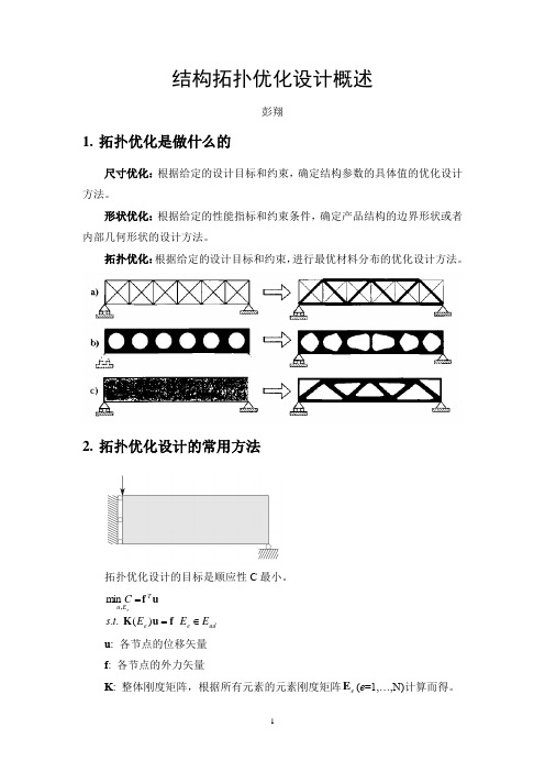
结构拓扑优化设计概述彭翔1. 拓扑优化是做什么的尺寸优化:根据给定的设计目标和约束,确定结构参数的具体值的优化设计方法。
形状优化:根据给定的性能指标和约束条件,确定产品结构的边界形状或者内部几何形状的设计方法。
拓扑优化:根据给定的设计目标和约束,进行最优材料分布的优化设计方法。
2. 拓扑优化设计的常用方法拓扑优化设计的目标是顺应性C 最小。
ade e T E u E E E t s C e∈==f u K uf )(..min ,u : 各节点的位移矢量 f : 各节点的外力矢量K : 整体刚度矩阵,根据所有元素的元素刚度矩阵e E (e =1,…,N)计算而得。
()∑==Ne e e E 1K K2.1 SIMP 法(Simple isotropic material with penalization)将各元素点的材料分布问题看作为各点的密度值问题,将弹性模量设置为各点的密度值的函数,进行密度值分布优化设计。
弹性模量()()1,0>=p E x x E ijkl p ijkl ρ()()Ω∈≤≤≤Ω⎰Ωx x V d x ,10;ρρ假设材料为各向同性的,将结构拓扑的变化转换为密度ρ的变化,并使用罚因子p 进行修正。
()()01,00ijklijkl ijkl E E E ====ρρ 常用步骤:1) 将设计域进行离散化,构建网格2) 根据给定的体积比,确定各点的密度值为初始值total e V V x max =3) 根据各元素的密度值,确定元素刚度矩阵,进行设计目标(顺应性C)的计算。
()∑==Ne e T e e e x E C 10u k u()()min 0min E E x E x E p e e e -+=[]1,0∈e x其中,e x 为第e 个元素的密度值;()e e x E 为第e 个元素的弹性模量;-3min 10=E 是一个无穷小量,表示空元素的弹性模量;0E 为元素的弹性模量,p 为系数,一般取为3。
ABAQUS拓扑优化手册

ABAQUS拓扑优化分析手册/用户手册分析手册:13. Optimization Technique优化技术13.1结构优化:概述13.1.1概述ABAQUS结构优化是一个帮助用户精细化设计的迭代模块。
结构优化设计能够使得结构组件轻量化,并满足刚度和耐久性要求。
ABAQUS提供了两种优化方法一一拓扑优化和形状优化。
拓扑优化(Topology optimization )通过分析过程中不断修改最初模型中指定优化区域的单元材料性质,有效地从分析的模型中移走/增加单元而获得最优的设计目标。
形状优化(Shape optimization)则是在分析中对指定的优化区域不断移动表面节点从而达到减小局部应力集中的优化目标。
拓扑优化和形状优化均遵从一系列优化目标和约束。
最优化方法(Optimization )是一个通过自动化程序增加设计者在经验和直觉从而缩短研发过程的工具。
想要优化模型,必须知道如何去优化,仅仅说要减小应力或者增大特征值是不够,做优化必须有更专门的描述。
比方说,想要降低在两种不同载荷工况下的最大节点力,类似的还有,想要最大化前五阶特征值之和。
这种最优化的目标称之为目标函数(ObjectFun ction)。
另外,在优化过程中可以同时强制限定某些状态参量。
例如,可以指定某节点的位移不超过一定的数值。
这些强制性的指定措施叫做约束(Constraint )。
ABAQUS/CAE可以创建模型然后定义、配置和执行结构优化。
更多信息请参考用户手册第十八章。
13.1.2 术语(Terminology)设计区域(Design area):设计区域即模型需要优化的区域。
这个区域可以是整个模型,也可以是模型的一部分或者数部分。
一定的边界条件、载荷及人为约束下,拓扑优化通过增加/删除区域中单元的材料达到最优化设计,而形状优化通过移动区域内节点来达到优化的目的。
设计变量(Design variables):设计变量即优化设计中需要改变的参数。
- 1、下载文档前请自行甄别文档内容的完整性,平台不提供额外的编辑、内容补充、找答案等附加服务。
- 2、"仅部分预览"的文档,不可在线预览部分如存在完整性等问题,可反馈申请退款(可完整预览的文档不适用该条件!)。
- 3、如文档侵犯您的权益,请联系客服反馈,我们会尽快为您处理(人工客服工作时间:9:00-18:30)。
fraction and then the program shows the correct optimal topology for comparison. In the literature, one can find a multitude of approaches for the solving of topology optimization problems. In the original paper Bendsøe and Kikuchi (1988) a so-called microstructure or homogenization based approach was used, based on studies of existence of solutions. The homogenization based approach has been adopted in many papers but has the disadvantage that the determination and evaluation of optimal microstructures and their orientations is cumbersome if not unresolved (for noncompliance problems) and furthermore, the resulting structures cannot be built since no definite length-scale is associated with the microstructures. However, the homogenization approach to topology optimization is still important in the sense that it can provide bounds on the theoretical performance of structures. An alternative approach to topology optimization is the so-called “power-law approach” or SIMP approach (Solid Isotropic Material with Penalization) (Bendsøe 1989; Zhou and Rozvany 1991; Mlejnek 1992). Here, material properties are assumed constant within each element used to discretize the design domain and the variables are the element relative densities. The material properties are modelled as the relative material density raised to some power times the material properties of solid material. This approach has been criticized since it was argued that no physical material exists with properties described by the power-law interpolation. However, a recent paper by Bendsøe and Sigmund (1999) proved that the power-law approach is physically permissible as long as simple conditions on the power are satisfied (e.g. p ≥ 3 for Poisson’s ratio equal to 1 3 ). To ensure existence of solutions, the power-law approach must be combined with a perimeter constraint, a gradient constraint or with filtering techniques (see Sigmund and Petersson 1998, for an overview). The power-law approach to topology optimization has been applied to problems with multiple constraints, multiple physics and multiple materials. Whereas the solution of the above mentioned approaches is based on mathematical programming techniques and continuous design variables, a number of papers have appeared on solving the topology optimization problem as an integer problem. Beckers (1999) success-
1 Introduction The Matlab code presented in this paper is intended for engineering education. Students and newcomers to the field of topology optimization can down-load the code from the web-page http://www.topopt.dtu.dk. The code may be used in courses in structural optimization where students may be assigned to do extensions such as multiple load-cases, alternative mesh-independency schemr possibility is to use the program to develop students’ intuition for optimal design. Advanced students may be asked to guess the optimal topology for given boundary condition and volume
Educational article
Struct Multidisc Optim 21, 120–127 Springer-Verlag 2001
A 99 line topology optimization code written in Matlab
O. Sigmund
Abstract The paper presents a compact Matlab implementation of a topology optimization code for compliance minimization of statically loaded structures. The total number of Matlab input lines is 99 including optimizer and Finite Element subroutine. The 99 lines are divided into 36 lines for the main program, 12 lines for the Optimality Criteria based optimizer, 16 lines for a meshindependency filter and 35 lines for the finite element code. In fact, excluding comment lines and lines associated with output and finite element analysis, it is shown that only 49 Matlab input lines are required for solving a well-posed topology optimization problem. By adding three additional lines, the program can solve problems with multiple load cases. The code is intended for educational purposes. The complete Matlab code is given in the Appendix and can be down-loaded from the web-site http://www.topopt.dtu.dk. Key words topology optimization, education, optimality criteria, world-wide web, Matlab code
121 fully solved large-scale compliance minimization problems using a dual-approach but other approaches based on genetic algorithms or other semi-random approaches require thousands of function evaluations even for small number of elements and must be considered impractical. Apart from above