APG1608VGAZC-RV;中文规格书,Datasheet资料
10. tp1608数据采集卡产品资料
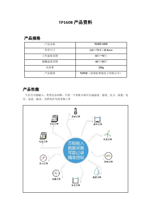
TP1608产品资料产品规格产品名称RS485-1608外形尺寸110×75.5×25.6mm工作温度范围30℃~70℃储藏温度范围-40℃~85℃仪表重185g产品展商TOPRIE(深圳拓普瑞电子有限公司)产品性能1.信号万能输入,类型自由切换,只需一个采集卡就可完成温度、湿度、压力、流量、电压、电流、振动、光照等信号的采集工作2.多种协议选择,更好的为您所用,采集卡支持三种协议:modbus-rtu协议、研华Adam4017协议、主动上报协议3.完美的隔离保护,更放心、安全的数据采集;电源与通道之间耐压1500VAC(50/60HZ),通道与通道之间600VAC(50/60HZ),被测物体带电也能正常运行。
4.高精度输入测量,展现更精准数值;热电偶、热电阻信号精度可达0.2%(F.S)0-5V精度可达0.05%F.S,4-20ma精度达0.05%F.S。
产品参数有效分辨率16位通道8路差分通道独立配置8路输入信号热电偶K,E,R,B,N,T,E,J,S,WRE5-26,WRE3-25热电阻Pt100,Cu50电流4-20mA,0-10mA,0-20mA电压0-5V,0-10V类型与温度范围J0~760℃K0~1370℃T-100~400℃E0~1000℃R00~1750℃S500~1750℃B500~1800℃PT100-200~600℃测量精度±0.2%F.S零漂移±3uV/℃采样周期1-19999s自主设定隔离电压3000Vdc故障与过压保护最大承受电压±400V满量程漂移±25ppm/℃;92dB(最小CMR@50/60Hz)记录模式电脑软件循环记录通讯RS485标准ModBus RTU通讯协议、Adam4017通讯协议、主动上报协议波特率1200,2400,4800,9600,38400,57600,115200bps电源+5V/DC或24V/DC电源保护电源反向保护机体材质采用CNC工艺氧化铝合金外形尺寸110×75.5×25.6mmEMI符合FCC Class A工作温度-30℃~+75℃储存温度-25℃~+85℃工作湿度5~95%无凝结数据采集卡软件展示极具友好的操作界面、更人性化界面设计,拥有曲线、数显、帮图、列表等多种窗口界面,满足各种使用场景和使用习惯细腻、灵活的曲线界面简单、大方的数显界面清晰、直观的列表界面动态、立体的帮图界面开发多种实用性功能,更便捷的数据处理,报表、图文一键生成,就是这么简单多坐标曲线显示功能Shift键+选中区域生成最大值、最小值、平均值功能Ctrl键+选中区域放大曲线功能曲线保存图片功能历史数据列表、曲线追踪查询功能数据时段一键导出多联系人短信报警功能曲线一键打印功能。
洛克韦尔自动化1608型号产品使用指南说明书

Technical DataOriginal InstructionsDySC Dynamic Voltage Sag Corrector Specifications Bulletin Number 1608Topic PageSummary of Changes2Overview2Bulletin 1608N MiniDySC Dynamic Sag Correctors3Bulletin 1608P Dynamic Sag Correctors7Bulletin 1608M MegaDySC Dynamic Sag Correctors12Additional Resources15DySC Dynamic Voltage Sag Corrector SpecificationsSummary of ChangesThis publication contains new and updated information as indicated in the following table.Topic PageAdded Product Overview2Added 1608N Product Selection3Added Bulletin 1608N Accessories6Added 1608P Product Selection7Added Bulletin 1608P Accessories11Added Bulletin 1608M Product Selection12Added Additional Resources section15OverviewThe Bulletin 1608 line of Dynamic Sag Correctors (DySC) are a unique and exclusive industrial power quality solution. Each DySC uses patented double conversion inverter technology that protects against the voltage sags and momentary outages that account for much manufacturing downtime.•Protects against short-term sags and interruptions that can impact production•Machine to facility-wide protection•Single- and three-phase products•Up to 5 seconds of ride through•Battery-free solution - eliminates requirement to swap batteries every 3…5 yearsOverviewBulletin1608N1608P1608MType MiniDySC ProDySC MegaDySCAmp Range2...6 12...50 25...50 100/110 200400 (2400)Voltage Range120…240V AC208…480V AC380…480V ACMounting DIN Rail Mount Panel Mount Panel Mount Floor MountPhase / Wiring Single Phase / L-L and L-N Three Phase/ 3-Wire and 4-WireRide Through up to 5 sBatteries Not requiredEnclosure NEMA Type 1Operating Temperature Range0…40 °C (32…104 °F)2Rockwell Automation Publication 1608-TD001B-EN-P - November 2018DySC Dynamic Voltage Sag Corrector Specifications Bulletin 1608N MiniDySC Dynamic Sag Correctors1608N Product SelectionMiniDySC Single Phase Voltage Sag Corrector - DIN Rail MountRated Current [A] Line Voltage [V] Wiring Category Runtime Cat. No.2 A 120VL-N Standard 1608N-002A120V2SL-N Extended 1608N-002A120V2E 208VL-L Standard 1608N-002A208V1SL-L Extended 1608N-002A208V1E 240VL-L Standard 1608N-002A240V1SL-L Extended 1608N-002A240V1EL-N Standard 1608N-002A240V2SL-N Extended 1608N-002A240V2E3 A 208VL-L Standard 1608N-003A208V1SL-L Extended 1608N-003A208V1E 230VL-N Standard 1608N-003A230V2SL-N Extended 1608N-003A230V2E 240VL-L Standard 1608N-003A240V1SL-L Extended 1608N-003A240V1EL-N Standard 1608N-003A240V2SL-N Extended 1608N-003A240V2E6 A 120V L-N Standard 1608N-006A120V2S L-N Extended 1608N-006A120V2EMiniDySC Single Phase Voltage Sag Corrector - Panel MountRated Current [A] Line Voltage [V] Wiring Category Runtime Cat. No.12 A 120VL-N Standard 1608N-012A120V2SL-N Standard 1608N-012A120V2S-R 208V L-L Standard 1608N-012A208V1S 220V L-N Standard 1608N-012A220V2S 230V L-N Standard 1608N-012A230V2S 240VL-L Standard 1608N-012A240V1SL-N Standard 1608N-012A240V2S25 A 120VL-N Standard 1608N-025A120V2SL-N Extended 1608N-025A120V2E208VL-L Standard 1608N-025A208V1SL-L Extended 1608N-025A208V1E220VL-N Standard 1608N-025A220V2SL-N Extended 1608N-025A220V2ERockwell Automation Publication 1608-TD001B-EN-P - November 201834Rockwell Automation Publication 1608-TD001B-EN-P - November 2018DySC Dynamic Voltage Sag Corrector Specifications1608N Specifications25 A230VL-N Standard 1608N-025A230V2S L-N Extended 1608N-025A230V2E 240VL-L Standard 1608N-025A240V1S L-L Extended 1608N-025A240V1E L-N Standard 1608N-025A240V2S L-NExtended 1608N-025A240V2E 50 A120V L-N Standard 1608N-050A120V2S L-N Extended 1608N-050A120V2E 208V L-L Standard 1608N-050A208V1S L-L Extended 1608N-050A208V1E 220VL-N Standard 1608N-050A220V2S L-N Extended 1608N-050A220V2E 230VL-N Standard 1608N-050A230V2S L-N Extended 1608N-050A230V2E 240VL-LStandard 1608N-050A240V1S L-L Extended 1608N-050A240V1E L-N Standard 1608N-050A240V2S L-NExtended1608N-050A240V2EElectrical Input/Output (Normal Mode—Static Switch)2…6 A12…50 AConnection Configuration Series-connected with load. Under normal line condition, the static switch passes utility voltage directly to the load Standard Input Voltage DySC 1 PH: 120, 208, 220, 230, 240V Voltage Range±10%Current Overload (Trip above these levels) 110% continuous, 150% @ 10 s, 200% @ 0.5 s,300% @ 10 cycles, 400% @ 3 cycles, 1000% Instantaneous —Current Overload (Static Switch) for 12A, 50A models — 200% @ 30 s, 400% @ 5 s, 600% @ 0.5 s Current Overload (Static Switch) for 25A models —200% @ 30 s, 280% @ 5 s, 450% @ 0.5 sFrequency50/60 Hz Auto Sensing Frequency Range (tracking) 45…65 HzSurge Protection Device (SPD) Built-in 3-Layers consisting of MOVs and Capacitors Efficiency 250 VA >94%, 500 VA>97%, 750 VA >96% > 98%Phase (wiring) 1 phase (L-L & L-N) Detection Voltage 88.5% of rated voltageResponse Time (typical)0.7 ms detection, 1.2 ms inverter reaction (<2 ms)MiniDySC Single Phase Voltage Sag Corrector - Panel Mount (Continued)DySC Dynamic Voltage Sag Corrector SpecificationsElectrical Output (Sag Correction Mode—Inverter)Output Voltage Matches pre-sag input voltageVoltage Regulation +/- 5% typical, +5% / -13% of nominal maxOutput Current Rated RMSCrest Factor (at rated load) 1.45Load Power factor range -0.5…+0.9, DC component <2% of rated currentVoltage Waveform (typical) Sine waveVoltage Sag Correction TimesSingle Event87% to 50% voltage remaining 5 s SR and ERSags to zero voltage remaining 50 ms or 200 ms (standard or extended run time DySCs). Based on nameplate ratings with a power factor of 0.7 Multiple EventsMax Sag Correction Time 5 s cumulative usageSequential Sag Recovery 0 s (assuming cumulative run-time available)Full Recovery Time Max 5 minMechanical Specifications2…6 A12...50 AEnclosure Ratings NEMA 1 (IP20)Cooling Forced air (500VA, 750VA) or natural convection (250VA)Forced AirAccess Lower front for connections Lower front for servicing and connections Accessibility (Wiring)Pluggable compression terminal block DIN compression terminal blockCommunications / User Interface2…6 A12...50 AIndicators 3 LEDs: Overload Trip, Normal, Alarm Normal and Alarm LEDsConnectivity************************************@1A OUTPUT OK and ALARM contacts, Form A, 24V DC at 1 AEnvironmental2…6 A12...50 AAmbient Temperature0…+50 °C (+32…+122 °F)0…+40 °C (+32…+104 °F)Storage Temperature-40°C…+75 °C (-40…+167 °F)Relative Humidity0…95% non-condensingAltitude Rated current available to 1000 m (3300 ft).De-rate output current 10% per 1000 m, from 1000…3000 m (9900 ft).Audible Noise<50 dBA at 1 mRockwell Automation Publication 1608-TD001B-EN-P - November 201856Rockwell Automation Publication 1608-TD001B-EN-P - November 2018DySC Dynamic Voltage Sag Corrector Specifications1608N Approximate DimensionsApproximate dimensions are shown in inches (mm) unless otherwise indicated. Dimensions are not to be used for manufacturing purposes.1608N Accessories2…6 Amp – DIN Rail MountRun Time Rating (VA) H x W x D in. [mm]Shipping Weight lb. [kg] Standard (SR)250 8.3 x 3.4 x 6.3 [210.8 x 86.4 x 160] 4.8 [2.18] 500 9.3 x 3.4 x 7.8 [236.2 x 86.4 x 198.1] 6.3 [2.86] 750 9.3 x 3.4 x 7.8 [236.2 x 86.4 x 198.1] 6.7 [3.04] Extended (ER)2508.3 x 5.8 x 6.3 [210.8 x 147.3 x 160] 8.0 [3.63] 500 9.3 x 5.8 x 7.8 [236.2 x 147.3 x 198.1] 9.5 [4.31] 7509.3 x 5.8 x 7.8 [236.2 x 147.3 x 198.1]10.2 [4.63]12…50 Amp – Panel MountRun Time Rating (A) H x W x D in. [mm] Shipping Weight lb. [kg] Standard (SR) 12, 25 22 x 10 x 4 [550.8 x 254 x 101.6] 18.6 [8.44] 50 21 x 19 x 4 [533.4 x 482.6 x 101.6] 34.5 [15.5] Extended (ER)25 21 x 19 x 4 [533.4 x 482.6 x 101.6] 32.5 [14.7] 5021 x 19 x 7 [533.4 x 482.6 x 177.8]51.5 [23.4]Bulletin 1608 AccessoriesTypeDescriptionCat. No. Bulletin 1608N - Single PhaseBypass, Single Phase, 25A, up tp 240V, L-L1608N-BP025A240V1 Bypass, Single Phase, 25A, up to 240V, L-N 1608N-BP025A240V2 Bypass, Single Phase, 50A, up to 240V, L-L 1608N-BP050A240V1 Bypass, Single Phase, 50A, up to 240V, L-N1608N-BP050A240V2DySC Dynamic Voltage Sag Corrector Specifications Bulletin 1608P Dynamic Sag Correctors1608P Product SelectionProDySC Three Phase Voltage Sag CorrectorRated Current [A] Line Voltage [V] Wiring Category Runtime Cat. No.25 A 208V3-Wire Standard 1608P-025A208V3S3-Wire Extended 1608P-025A208V3E4-Wire Standard 1608P-025A208V4S4-Wire Extended 1608P-025A208V4E 380V3-Wire Standard 1608P-025A380V3S3-Wire Extended 1608P-025A380V3E4-Wire Standard 1608P-025A380V4S4-Wire Extended 1608P-025A380V4E 400V3-Wire Standard 1608P-025A400V3S3-Wire Extended 1608P-025A400V3E4-Wire Standard 1608P-025A400V4S4-Wire Extended 1608P-025A400V4E 415V3-Wire Standard 1608P-025A415V3S3-Wire Extended 1608P-025A415V3E4-Wire Standard 1608P-025A415V4S4-Wire Extended 1608P-025A415V4E 480V3-Wire Standard 1608P-025A480V3S3-Wire Extended 1608P-025A480V3E4-Wire Standard 1608P-025A480V4S4-Wire Extended 1608P-025A480V4E50 A 208V3-Wire Standard 1608P-050A208V3S3-Wire Extended 1608P-050A208V3E4-Wire Standard 1608P-050A208V4S4-Wire Extended 1608P-050A208V4E380V3-Wire Standard 1608P-050A380V3S3-Wire Extended 1608P-050A380V3E4-Wire Standard 1608P-050A380V4S4-Wire Extended 1608P-050A380V4E400V3-Wire Standard 1608P-050A400V3S3-Wire Extended 1608P-050A400V3E4-Wire Standard 1608P-050A400V4S4-Wire Extended 1608P-050A400V4E415V3-Wire Standard 1608P-050A415V3S3-Wire Extended 1608P-050A415V3E4-Wire Standard 1608P-050A415V4S4-Wire Extended 1608P-050A415V4ERockwell Automation Publication 1608-TD001B-EN-P - November 20187DySC Dynamic Voltage Sag Corrector Specifications50 A (cont’d)480V 3-Wire Standard 1608P-050A480V3S 3-Wire Extended 1608P-050A480V3E 4-Wire Standard 1608P-050A480V4S 4-Wire Extended 1608P-050A480V4E100 A 208V3-Wire Standard 1608P-100A208V3S3-Wire Extended 1608P-100A208V3E4-Wire Standard 1608P-100A208V4S4-Wire Extended 1608P-100A208V4E 380V3-Wire Standard 1608P-100A380V3S3-Wire Extended 1608P-100A380V3E4-Wire Standard 1608P-100A380V4S4-Wire Extended 1608P-100A380V4E 400V3-Wire Standard 1608P-100A400V3S3-Wire Extended 1608P-100A400V3E4-Wire Standard 1608P-100A400V4S4-Wire Extended 1608P-100A400V4E 415V3-Wire Standard 1608P-100A415V3S3-Wire Extended 1608P-100A415V3E4-Wire Standard 1608P-100A415V4S4-Wire Extended 1608P-100A415V4E 480V3-Wire Standard 1608P-100A480V3S3-Wire Extended 1608P-100A480V3E4-Wire Standard 1608P-100A480V4S4-Wire Extended 1608P-100A480V4E110 A 480V 3-Wire Standard 1608P-110A480V3S3-Wire Extended 1608P-110A480V3E3-Wire Extended 1608P-110A480V3E-HC 4-Wire Standard 1608P-110A480V4S4-Wire Extended 1608P-110A480V4E4-Wire Extended 1608P-110A480V4E-HCProDySC Three Phase Voltage Sag Corrector (Continued)Rated Current [A] Line Voltage [V] Wiring Category Runtime Cat. No.8Rockwell Automation Publication 1608-TD001B-EN-P - November 2018Rockwell Automation Publication 1608-TD001B-EN-P - November 20189DySC Dynamic Voltage Sag Corrector Specifications1608P Specifications200 A208V 3-Wire Standard 1608P-200A208V3S 4-Wire Standard 1608P-200A208V4S 380V 3-Wire Standard 1608P-200A380V3S 4-Wire Standard 1608P-200A380V4S 400V3-Wire Standard 1608P-200A400V3S 4-Wire Standard 1608P-200A400V4S 415V3-Wire Standard 1608P-200A415V3S 4-Wire Standard 1608P-200A415V4S 480V3-Wire Standard 1608P-200A480V3S 4-WireStandard 1608P-200A480V4S 3-Wire Standard 1608P-200A480V3S-HC (1)4-WireStandard1608P-200A480V4S-HC (1)(1)1608P-xx…-HC 200 A devices provide 78 ms ride-through time at zero volts, and includes an integrated three breaker bypass.Electrical Input/Output (Normal Mode—Static Switch)25/50 A110/110A200 A200 A HCConnection Configuration Series-connected with load. Under normal line condition, the static switch passes utility voltage directly to the load Standard Input Voltage DySC 3 PH: 208, 380, 400, 415, 480V 480VVoltage Range ±10% Current Overload 150% @ 30 s,400% @ 5 s,600% @ 0.5 s 200% @ 30 s,400% @ 5 s,600% @ 0.5 s150% @ 30 s 400% @ 5 s 600% @ 0.5 sFrequency50/60 Hz Auto Sensing Frequency Range (tracking) 45…65 Hz48…62 HzSurge Protection Device (SPD) Built-in 3-Layers consisting of MOVs and Capacitors Efficiency > 99% @ 480V Phase (wiring) 3 PH (3-Wire and 4-Wire)Detection Voltage 88.5% of rated voltageResponse Time (typical)0.7 ms detection, 1.2 ms inverter reaction (<2 ms)Electrical Output (Sag Correction Mode—Inverter)25/50 A 110/110A200 A200 A HCOutput Voltage Pre-sag rms voltageVoltage Regulation +/- 5% typical, +5% / -13% of nominal maxOutput Current Rated RMS, Not rated for DC loads: max allowable 2% DC loading.Crest Factor (at rated load) 1.45LoadPower factor range -0.5…+0.9, DC component <2% of rated current Voltage Waveform (typical)Sine waveProDySC Three Phase Voltage Sag Corrector (Continued)Rated Current [A]Line Voltage [V] Wiring Category Runtime Cat. No.DySC Dynamic Voltage Sag Corrector SpecificationsVoltage Sag Correction Times25/50 A 110/110A 200 A200 A HC Single Event87…50% voltage remaining 5 sAll three phases to zero voltage remaining 50 ms or 200 ms (SR or ER).Based on load at nameplateratings with a power factor of 0.733...50 ms or 133...200 ms(SR or ER). Based on load atnameplate ratings with a powerfactor of 0.750 ms based on nameplateratings with a power factor of 0.778 ms based on nameplateratings with a power factor of 0.7Multiple EventsMax Sag Correction Time 5 s cumulative usageSequential Sag Recovery 0 s (assuming cumulative run-time available)Full Recovery Time Max 5 minMechanical Specifications25/50 A 110/110A 200 A200 A HC Enclosure Ratings NEMA 1 (IP20)Cooling Filtered forced airAccess Front for servicing and connectionsAccessibility (Wiring)Screw terminal blocks Mechanical lugsCommunications / User Interface25/50 A 110/110A 200 A200 A HC Indicators LCD ScreenConnectivity SAG EVENT, OUTPUT OK, and ALARM contacts, Form A, 24V DC at 1 AEnvironmental25/50 A 110/110A 200 A200 A HC Ambient Temperature0…+40 °C (+32…+104 °F)Storage Temperature-40°C…+75°C (-40…+167 °F)Relative Humidity0…95% non-condensingAltitude Rated current available to 1000 m (3300 ft). De-rate output current 10% per 1000 m, from 1000…3000 m (9900 ft). Audible Noise< 55 dBA at 1 m<67 dBA at 1 m10Rockwell Automation Publication 1608-TD001B-EN-P - November 2018Rockwell Automation Publication 1608-TD001B-EN-P - November 201811DySC Dynamic Voltage Sag Corrector Specifications1608P Approximate DimensionsApproximate dimensions are shown in inches (mm) unless otherwise indicated. Dimensions are not to be used for manufacturing purposes.1608P Accessories25…50 AmpRun Time Rating (A) H x W x D in. [mm] Shipping Weight lb. [kg] Standard (SR) 25 32 x 26 x 14 [813 x 660 x 356] 277 [126] 50 38 x 38 x 14 [965 x 965 x 356] 330 [150] Extended (ER)25 32 x 26 x 14 [813 x 660 x 356] 307 [140] 5038 x 38 x 14 [965 x 965 x 356]398 [181]100/110 AmpRun Time Wiring Type H x W x D in. [mm]Shipping Weight lb. [kg] Standard (SR)3-Wire 57.1 x 29 x 24.7 [1449 x 737 x 627]787 [357] 4-Wire 772 [351] Extended (ER) 3-Wire 77.1 x 29 x 24.7[1957 x 737 x 627]937 [426] 4-Wire922 [419]200 AmpWiring Type H x W x D in. [mm]Shipping Weight lb. [kg] 3-Wire 78.6 x 42.4 x 34.6 [1983 x 1076 x 878]1,470 [667] 4-Wire1,408 [639]Bulletin 1608 AccessoriesTypeDescriptionCat. No. Bulletin 1608P - Three PhaseBypass, Three Phase, 25A, up to 480V1608P-BP025A480V3 Bypass, Three Phase, 50A, up to 480V 1608P-BP050A480V3 Bypass, Three Phase, 110A, up to 480V1608P-BP110A480V312Rockwell Automation Publication 1608-TD001B-EN-P - November 2018DySC Dynamic Voltage Sag Corrector SpecificationsBulletin 1608M MegaDySC Dynamic Sag Correctors1608M Product SelectionContact your local Rockwell Automation sales office or Allen-Bradley distributor for MegaDySC systems over 400A.T o ensure successful integration, the MegaDySC unit requires commissioning from factory authorized personnel.Rated Current [A]Line Voltage [V]Wiring Category Runtime Cat. No. 400A380V3-WireStandard 1608M-400A380V3S Extended 1608M-400A380V3E 4-Wire Standard 1608M-400A380V4S Extended 1608M-400A380V4E 400V3-WireStandard 1608M-400A400V3S Extended 1608M-400A400V3E 4-Wire Standard 1608M-400A400V4S Extended 1608M-400A400V4E 415V3-WireStandard 1608M-400A415V3S Extended 1608M-400A415V3E 4-WireStandard 1608M-400A415V4S Extended 1608M-400A415V4E 460V3-WireStandard 1608M-400A460V3S Extended 1608M-400A460V3E 4-Wire Standard 1608M-400A460V4S Extended 1608M-400A460V4E 480V3-WireStandard 1608M-400A480V3S Extended 1608M-400A480V3E 4-WireStandard 1608M-400A480V4S Extended1608M-400A480V4EDySC Dynamic Voltage Sag Corrector Specifications Bulletin 1608M SpecificationsElectrical Input/Output (Normal Mode—Static Switch)Connection Configuration Series-connected with load. Under normal line condition, the static switch passes utility voltage directly to the loadStandard Input Voltage DySC 3 PH: 380, 400, 415, 480VVoltage Range ±10%Static Bypass Current100% rated rms continuous, 150…400% @ 5 s, 400…600% @ 0.5 s, 600% @ 0.1 s Frequency 50/60 Hz Auto SensingFrequency Range (tracking) 45…65 HzSurge Protection Device (SPD) Output SPD, 80kA/modeEfficiency >99%Phase (wiring) 3 phases + Ground (3-wire models) or 3 phases + Neutral + Ground (4-wire models) Detection Voltage 88.5% of rated voltageResponse Time (typical) 0.7 ms detection, 1.2 ms inverter reaction (2 ms)Electrical Output (Sag Correction Mode—Inverter)Output Voltage Pre-sag rms voltageVoltage Regulation +/- 5% typical, +5% / -13% of nominal maxOutput Current Rated RMSNot rated for DC loads; max. allowable 2% DC loadingCrest Factor (at rated load) 1.45Load Power factor range -0.5…+0.9, DC component <2% of rated current Voltage Waveform (typical) Sine waveVoltage Sag Correction TimesSingle Event87…50% voltage remaining 5 s SR and ERAll three phases to zero voltage remaining 50 ms or 200 ms (standard or extended run time DySCs). Based on nameplate ratings with a power factor of 0.7Multiple EventsMax Sag Correction Time 5 s cumulative usageSequential Sag Recovery 0 s (assuming cumulative run-time available)Full Recovery Time Max 5 minMechanical SpecificationsEnclosure Ratings NEMA 1 (IP20)Cooling Filtered forced airCable Entry Top or bottom of switchboardAccess Front for servicing and connectionsAccessibility (Wiring)Mechanical LugsRockwell Automation Publication 1608-TD001B-EN-P - November 20181314Rockwell Automation Publication 1608-TD001B-EN-P - November 2018DySC Dynamic Voltage Sag Corrector Specifications1608M Approximate DimensionsApproximate dimensions are shown in inches (mm) unless otherwise indicated. Dimensions are not to be used for manufacturing purposes.Communications / User InterfaceIndicators LCD screenConnectivitySAG EVENT, OUTPUT OK, and ALARM contacts, Form A, 24V DC at 1 AEnvironmentalAmbient Temperature 0…+40°C (32…+104 °F)Storage Temperature -40°C…+75°C (-40…+167 °F)Relative Humidity 0…95% non-condensingAltitude Rated current available to 1000 m (3300 ft). De-rate output current 10% per 1000 m, from 1000…3000 m (9900 ft).Audible Noise<70dBA at 1 mRated Current [A]Run Time Wiring Type H x W x D in. [mm]Shipping Weight lb. [kg] 400Standard3-Wire 94 X 69.3 X 33.1 [2388 X 1759 X 840] 2867 lb [1300kg] 4-Wire 2831 lb [1284 kg] Extended 3-Wire 94 X 87.3 X 33.1 [2388 X 2216 X 840] 3731 lb [1692 kg] 4-Wire 3695 lb [1676 kg] 800Standard3-Wire 103 X 128.5 X 51.1 [2614 X 3264 X 1297]7800 lb [3538kg] 4-Wire 7800 lb [3538kg] Extended 3-Wire 103 X 164.5 X 51.1 [2614 X 4178 X 1297] 8632 lb [3915 kg] 4-Wire 8632 lb [3915 kg] 1200Standard3-Wire 103 X 165.5 X 51.1 [2614 X 4204 X 1297] 10,350 lb [1300kg] 4-Wire 10,350 lb [1300kg] Extended 3-Wire 103 X 219.5 X 51.1 [2614 X 5575 X 1297] 11,598 lb [1692 kg] 4-Wire 11,598 lb [1692 kg] 1600Standard3-Wire 103 X 202.5 X 51.1 [2614 X 5144 X 1297] 13,300 lb [6033kg] 4-Wire 13,300 lb [6033kg] Extended 3-Wire 103 X 274.5 X 51.1 [2614 X 6972 X 1297] 14,964 lb [6788 kg] 4-Wire 14,964 lb [6788 kg] 2000Standard3-Wire 103 X 239.5 X 51.1 [2614 X 6083 X 1297] 16,250 lb [7371kg] 4-Wire 16,250 lb [7371kg] Extended 3-Wire 103 X 329.6 X 51.1 [2614 X 8372 X 1297] 18,330 lb [8314 kg] 4-Wire 18,330 lb [8314 kg] 2400Standard3-Wire 103 X 276.5 X 51.1 [2614 X 7023 X 1297] 18,800 lb [8528kg] 4-Wire 18,800 lb [8528kg] Extended3-Wire 103 X 384.6 X 51.1 [2614 X 9769 X 1297]21,296 lb [9660 kg] 4-Wire21,296 lb [9660 kg]DySC Dynamic Voltage Sag Corrector Specifications Additional ResourcesThese documents contain additional information concerning related products from Rockwell Automation.Resource DescriptionIndustrial Automation Wiring and Grounding Guidelines, publication 1770-4.1Provides general guidelines for installing a Rockwell Automation industrial system. Product Certifications website, rok.auto/certifications.Provides declarations of conformity, certificates, and other certification details.Y ou can view or download publications at /global/literature-library/ overview.page.Rockwell Automation Publication 1608-TD001B-EN-P - November 201815Allen-Bradley, LISTEN. THINK. SOLVE., Rockwell Automation, and Rockwell Software are trademarks of Rockwell Automation, Inc.Trademarks not belonging to Rockwell Automation are property of their respective companies.Publication 1608-TD001B-EN-P - November 2018Supersedes Publication 1608-TD001A-EN-P - July 2014Copyright © 2018 Rockwell Automation, Inc. All rights reserved. Printed in the U.S.A.Rockwell Automation SupportUse the following resources to access support information.Documentation FeedbackY our comments will help us serve your documentation needs better. If you have any suggestions on how to improve this document, complete the How Are W e Doing? form at /idc/groups/literature/documents/du/ra-du002_-en-e.pdf .Technical Support CenterKnowledgebase Articles, How-to Videos, FAQs, Chat,User Forums, and Product Notification /knowledgebaseLocal Technical Support Phone Numbers Locate the phone number for your country./global/support/get-support-now.pageDirect Dial Codes Find the Direct Dial Code for your product. Use thecode to route your call directly to a technical supportengineer./global/support/direct-dial.pageLiterature LibraryInstallation Instructions, Manuals, Brochures, and Technical Data./literatureProduct Compatibility and Download Center (PCDC)Get help determining how products interact, check features and capabilities, and find associated firmware./global/support/pcdc.pageRoc kw ell Otomasyon Ticaret A .Ş., K ar Plaza İş Mer k ezi E B lo k K at:6 34752 İçeren köy, İstanbul, T el: +90 (216) 5698400Rockwell Automation maintains current product environmental information on its website at /rockwellautomation/about-us/sustainability-ethics/product-environmental-compliance.page .。
NCP1608中文
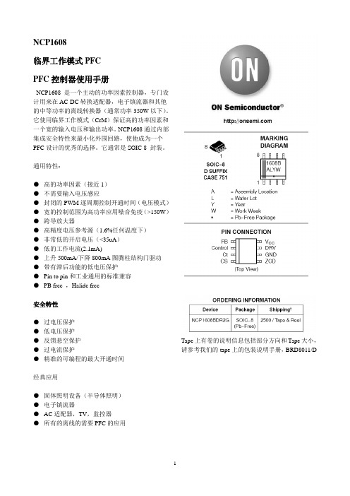
NCP1608临界工作模式PFCPFC控制器使用手册NCP1608 是一个主动的功率因素控制器,专门设计用来在AC-DC转换适配器,电子镇流器和其他的中等功率的离线转换器(通常功率350W以下)。
它使用临界工作模式(CrM)保证高的功率因素和一个宽的输入电压和输出功率。
NCP1608通过内部集成安全特性来最小化外围回路,使他成为一个PFC设计的优秀的选择。
它通常是SOIC-8 封装。
通用特性:●高的功率因素(接近1)●不需要输入电压感应●封闭的PWM逐周期控制开通时间(电压模式)●宽的控制范围为高功率应用噪音免疫(>150W)●跨导放大器●高精度电压参考源(1.6%任何温度下)●非常低的开启电压(<35uA)●低的工作电流(2.1mA)●上升500mA/下降800mA图腾柱结构门驱动●带有滞后功能的低电压保护●Pin to pin和工业通用的标准兼容●PB free ,Halide free安全特性●过电压保护●低电压保护●反馈悬空保护●过电流保护●精准的可编程的最大开通时间经典应用●固体照明设备(半导体照明)●电子镇流器●AC适配器,TV,监控器●所有的离线的需要PFC的应用Tape上有卷的说明信息包括部分方向和Tape大小,请参考我们的tape上的包装说明手册,BRD8011/D图1经典应用图2 内部结构框图表格1:pin针功能说明超过最大额定值可能损坏芯片。
最大额定值仅仅是加的电压,在正常工作中以上情况不能适用。
长期的暴漏于以上情况会影响芯片的信赖性。
1.这个芯片包括静电放电(ESD)保护达到以下测试:Pin1-8:人体模型超过2000V 每个JEDEC 标准JESD22-A114E机器模型办法200V 每个JEDEC 标准JESD22-A115A 。
表格3 电气特性V FB=2.4V,V Control = 4 V, Ct = 1 nF, V CS = 0 V, V ZCD = 0 V, C DRV = 1 nF, V CC = 12 V,除非另有说明。
MPZ1608_datasheet

Ferrite Beads SMDSize: JIS/IEC 1608, EIA 0603TDK has manufactured MPZ2012 type as EMI countermeasure product for power line, and now maximizes impedance to 600Ω (at 100MHz) and rated current to 1A, while minimizes Rdc under 150m Ω as 1608 type.FEATURES•This type is the best for energy-saving in the low DC resistance.•The products contain no lead and also support lead-free soldering.•It is a product conforming to RoHS directive.APPLICATIONSNoise suppression of personal computers, USB/IEEE1394interfaces, HDDs, CD-ROMs, DVDs, DSCs, LCD panels, cellular phones, etc.PRODUCT IDENTIFICATION (1)Series name (2)Dimensions L ×W (3)Material code(4)Nominal impedance 221: 220Ω at 100MHz (5)Characteristic type (6)Packaging style T: TapingELECTRICAL CHARACTERISTICS∗Please refer to the graph of RATED CURRENT vs. TEMPERATURE CHARACTERISTICS(DERATING) about the rating current at 85°C or more in temperature of the product.SHAPES AND DIMENSIONS/RECOMMENDED PC BOARD PATTERNTEMPERATURE RANGESPACKAGING STYLE AND QUANTITIESRATED CURRENT vs. TEMEPERATURE CHARACTERISTICS (DERATING)RECOMMENDED SOLDERING CONDITION REFLOW SOLDERINGPart No.Impedance (Ω)[100MHz]DC resistance(Ω)max.Rated current ∗(A)max.Thickness (T)mm ΩMPZ1608S600A 60±25%0.02 3.50.6MPZ1608S101A 100±25%0.0330.6MPZ1608S601A 600±25%0.1510.8MPZ1608Y151B 150±25%0.07 1.80.8MPZ1608D300B 30±10Ω0.07 1.80.8MPZ1608D101B 100±25%0.15 1.00.8MPZ 1608 S 221A T (1) (2) (3) (4) (5) (6)Thickness(T)Weight Operating/storage–55 to +125°CTaping4000 pieces/reel•Please contact our Sales office when your application are considered the following:The device ’s failure or malfunction may directly endanger human life (e.g. application for automobile/aircraft/medical/nuclear power devices, etc.)•Conformity to RoHS Directive: This means that, in conformity with EU Directive 2002/95/EC, lead, cadmium, mercury, hexavalent chromium, and specific bromine-based flame retardants, PBB and PBDE, have not been used, except for exempted applications.Ferrite Beads SMDSize: JIS/IEC 1608, EIA 0603TYPICAL ELECTRICAL CHARACTERISTICS Z, X, R vs. FREQUENCY CHARACTERISTICS MPZ1608S300A MPZ1608S600AMPZ1608S101AMPZ1608S221AMPZ1608R391AMPZ1608S601AMPZ1608Y600BMPZ1608Y101BMPZ1608Y151BMPZ1608D300BMPZ1608D600BMPZ1608D101B。
1241.1608;中文规格书,Datasheet资料
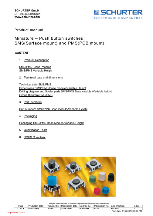
Product manualMiniature – Push button switchesSMS(Surface mount) and PMS(PCB mount). CONTENT1. Product_DescriptionSMS/PMS_Base_moduleHeightVariableSMS/PMS2. Technical data and dimensionsSMS/PMSTechnicaldataDimensions SMS/ PMS Base module/Variable HeightDrilling diagram and Solder pads SMS/PMS Base module /Variable height Circuit Diagram SMS/PMS3. Part_numbersPart numbers SMS/PMS Base module/Variable Height4. PackagingPackaging SMS/PMS Base Module/Variable Height5. Qualification Tests6. ROHS Compliant1 Description1.1 SMS/PMS Base moduleMiniature push button switches with a low height of 4,55 - 4,95 mm for surface mounting (SMS) and PCBmounting (PMS).The SMS has large flat surfaces on the top side as well as on the other sides, which are also parallel to each other. This makes the SMS a perfect switch for automatic mounting.The SMS switch is suitable for the SMD soldering process "IR-Reflow".The switch comes with the SMD-leads "Gullwing and J". With J-leads the switch can be lined up with a spacing of 1/2" in one coordinate direction, and with > 13,5 mm in the other coordinate direction. With Gullwing-leads, the switch can be arranged with a spacing of 1/2" in one coordinate direction, and in the other coordinate direction with > 17,5 mm.A minimum spacing of 1/2" to 15 mm is necessary for the PCB version.Basically, the SMS and PMS come in two basic versions concerning the degree of protection. Available are IP 40 and IP 67. According to the degree of protection the IP 40 version is not proof against fluxing and washing, whereas the IP 67 version is. Consequently, the IP 67 version can be exposed to the specified soldering and cleaning processes.The miniature push button switches feature a very good tactile response with an actuation force of about 2N. SMS and PMS are also available with an elongated actuator. These variants serve as base modules for the SMS/PMS variable height version.1.2 SMS/PMS Variable HeightThe variable height SMS/PMS consists of the SMS/PMS base module with elongated actuator and a slip-on button with eight variable heights.The PMS will be supplied with a mounted button. The button for the SMS has to be ordered separately. After soldering, the button must be put on the base module with elongated actuator.Heights between 8,5 mm and 13,75 mm for the SMS and 8,35 mm and 13,60 mm for the PMS are available. Depending on the base module being used, degree of protection for the variable height SMS/PMS is IP 40 or IP 67.2 Data and dimensional drawings2.1 Technical Data SMS/PMS Base module/Variable HeightElectrical data: IP40IP67 Contact material Gold ; Gold/Silver (1) GoldSwitching voltage max. 30V AC/ 42V DC 30V AC/ 42V DCSwitching current max. 50 mA 50 mARated breaking capacity 12 V/10 mA 12 V/10 mALifetime (at 12V/10mA) >1 x 10⁶cycles >1 x 10⁶cyclesLifetime (at 24V/80mA) - ; >1x10⁵ (1) -Initial contact resistance new (IEC 512-2 mV-method) <50 mOhm <50 mOhmInitial contact resistance after 1 x 10⁶ cycles <150 mOhm <150 mOhmInsulation resistance (IEC 512-2) > 1x 10⁸ Ohm > 1x 10⁸ OhmContact bounce time typ. 0,15 ms typ. 0,15 msIP67 Mechanical data: IP40Actuating force 1,8±0,4 N 2,2±0,4 NActuating travel 0,35±0,1 mm 0,35±0,1 mmMechanical strength (force axial, load 1 min.) max. 100 N max. 100 NLifetime(IEC 512-5. Test 9a. Actuating force 5N) >1x 10⁶ cycles >1x 10⁶Soldering data:SMS PMSIP40/IP67 IP40/IP67Soldering method IR Reflow Wave solderingSoldering heat resistance 245 °C/5sec. 248,5 °C/1sec(1)Recommended IR-Reflow Profile for SMSTolerance for Temperature settings T +0°C (according to JEDEC J-STD-020C, July 2004) Used Solder: Omnix O338 (Sn95.5%/Ag4%/Cu0.5%), Alpha Metals Loetsysteme GmbHRecommended Wave Soldering Profile for PMSWave Soldering Equipment: ERSA EMS 3300 Throughput speed: 1m / minSolder type:Sn100C from Nihon Superior (Balver-Solder) Flux material:AW30 Fa. Otto Adjustments Heating ZonesUpper Zone : 280 °C 300 °CLower Zone:450°C500 °C 560 °COther data:SMS PMS SMS PMSIP40 IP40 IP67 IP67Operating temperature(°C) -40 to 85 -40 to 85 -40 to 85 -40 to 85Storage temperature(°C) -40 to 85 -40 to 85 -40 to 85 -40 to 85Degree of protection (DIN 40050) IP40 IP40 IP67 IP67Cleaning agent proofZestronZestronapplied test agent 3) ZestronZestronFlux proof 1) _______ _______ given givenWash proof 2)______________given given1) Visual inspection of switch chamber after immersion in coliophonium solution flux for 3 seconds.2) Inspection of switch chamber after washing process3) CKW and FCKW free mix made of water soluable GlykoletherMechanical data:SMS/PMS SMS/PMS Component Flammabilityrating IP40IP67Socket UL94 V-0 Thermoplast (PA 4.6) Thermoplast (PA 4.6)(PPS) Actuator UL94 V-0 Thermoplast(PPS) ThermoplastCover plate X12 Cr Ni 17 7 X12 Cr Ni 17 7Sealing membrane UL94 HB ________ VMQ Elongated button UL94 V-2 Thermoplast (PC) Thermoplast(PC)Electrical data(material): SMS/PMSSMS/PMSIP40 IP67 Snap dome X12 CrNi 17 7 gold plated on contact sideContacts CuZn37with Ni/Au coated; with Ag coated (1)with Sn coatedTerminals(leads) CuZn372.2 Dimensions SMS/PMS Base module/variable heightSMS Gullwing Base module SMS J-lead Base module PMS PCB Base moduleSMS Gullwing Variable height SMS J-lead Variable height PMS PCB Variable heightSMS Gullwing and J lead with elongated button PMS PCB with elongated buttonGullwing J-AnschlussTotal height information: See point 3.1, Part numbers SMS und PMS Variable height, SMS elongated button must be ordered separately.2.3 Drilling diagram and Solder pads SMS/PMS Base module/variable height Gullwing lead J-lead2.4 Circuit Diagram SMS/PMS3 Part numbers3.1 Part numbers SMS/PMS Base module/Variable HeightPart-Nr. Base moduleType IP40 IP67 Gullwing lead 1241.1600.XX 1241.1606.XX J-lead 1241.1601.XX 1241.1607.XX Through hole lead 1241.1602 1241.1608Part-Nr. Elongated base moduleType IP40 IP67 Gullwing lead 1241.1612.XX 1241.1618.XX J-lead 1241.1613.XX 1241.1619.XX Through hole lead 1241.1614 1241.1620Ordering example______________ Base module_______________________1241.XXXX.XXIndex 11 loose in boxesIndex 23 Blister tapePart-Nr. Variable height PMSHeight in mm IP 40 IP67 Color8,35 1241.1624.11241.1625.1 Yellow1241.1625.2 Orange 9,10 1241.1624.29,85 1241.1624.31241.1625.3 Red1241.1625.4 Blue 10,60 1241.1624.41241.1625.5 Green 11,35 1241.1624.512,10 1241.1624.61241.1625.6 Grey1241.1625.7 Black 12,85 1241.1624.71241.1625.8 White 13,60 1241.1624.8Part-Nr. Elongated buttons for SMSSwitch height SMS with mountedPart-Nr. Color buttons in mm8,50 0862.8101 Yellow9,25 0862.8102 Orange10,00 0862.8103 Red10,75 0862.8104 Blue11,50 0862.8105 Green12,25 0862.8106 Grey13,00 0862.8107 Black13,75 0862.8108 White4 Packaging4.1 Packaging SMS/PMS Base module/Variable Heightloose in boxes SMS/PMS - Index 11 for SMS 100 pieces tape and reel for SMS base module - Index 23 700 pieces tape and reel for SMS elonged. base module -Index 23 450 pieces5 Qualification Tests6 ROHS Compliant分销商库存信息: SCHURTER 1241.1608。
ADG1608_1609[2]
![ADG1608_1609[2]](https://img.taocdn.com/s3/m/52bc8720482fb4daa58d4bec.png)
ADG1608/ADG1609
FEATURES
4.5 Ω typical on resistance 1 Ω on-resistance flatness Up to 470 mA continuous current ±3.3 V to ±8 V dual-supply operation 3.3 V to 16 V single-supply operation No VL supply required 3 V logic-compatible inputs Rail-to-rail operation 16-lead TSSOP and 16-lead, 3 mm × 3 mm LFCSP
A0 A1 EN
Figure 2.
The low on resistance of these switches make them ideal solutions for data acquisition and gain switching applications where low on resistance and distortion is critical. The on-resistance profile is very flat over the full analog input range, ensuring excellent linearity and low distortion when switching audio signals.
FUNCTIONAL BLOCK DIAGRAMS
ADG1608
1608全彩共阳-雾面胶体 用途参数

承认书SPECIFICATION FOR APPROVAL 客户Customer:客户品号Customer P/N:鑫光硕品号Xgs Model: XGS-PB1608UEUGUB-JG04-A规格Specification:1608全彩共阳-雾面胶体 制作Prepared By:李忠审核Checked By:Customer Confirmation客户确认采购部Pur Dept By品质部QA Dept By工程部E ng Dept By深圳市鑫光硕科技有限公司SHEN ZHEN XIN GUANG SHUO TECHNOLOGY CO.,LTD公司地址:广东省深圳市宝安区沙井万丰村前路31号8楼一厂地址:广东省深圳市龙岗区嶂背创业二路18-1号·Customer:Technical Data SheetPN:XGS-PB1608UEUGUB-JG04-AFor:IF=20mAContents1.Features2.Applications3.Package dimensions4.Absolute maximum rating5.Electrical optical characteristics6.BIN range7.Package label8.Soldering pad dimensions9.Soldering conditions10.Package tape specifications11.Typical electro-optical characteristics curves12.Reliability test items and conditions13.Cautions14.NotePart No.XGS-PB1608UEUGUB-JG04-AEmitted Color Red Green Blue Len's Color White Diffused Chip Material AlGaInP InGaN InGaN----◆Features:Compatible with automatic placement equipmentCompatible with reflow solder processLow power consumption and wide viewing angleThis product doesn’t contain restriction Substance,comply ROHS standard.◆Applications:Automotive and TelecommunicationFlat backlight for LCD,switch and symbol in telephone and faxGeneral use for indicators◆Package Dimensions:Unit:mmTolerance:±0.1 Electrodes:Au PlatingEncapsulating Resin:Epoxy ResinPackage:BT Resin◆Absolute Maximum Rating(Ta=25℃)Parameter SymbolValueUnit R G BPower Dissipation P d608080MwPulse Forward Current I FP303030mADC Forward Current I F20mAReverse V oltage V R5V Operating Temperature Range Topr-40℃~85℃℃Storage Temperature Range Tstg-40℃~100℃℃FP≤≤◆Electrical Optical Characteristics(Ta=25℃)Parameter Symbol Min Typ.Max.Unit TestConditionLuminous Intensity I VRed220300380mcd I F=20mA Green5506801000Blue150280400Forward V oltage VFRed 1.7 2.0 2.5V I F=20mA Green 2.8 3.1 3.4Blue 2.8 3.1 3.4Reverse Current I R Red----10uA V R=5VDominant WavelengthλdRed615620630nm I F=20mA Green515525530Blue460470475Spectral Line Half WidthΔλRed--20--nm I F=20mA Green--30--Blue--30--Viewing Angle2θ1/2/--120--Deg.I F=20mA Notes:1.Tolerance of Luminous Intensity±10%2.Tolerance of Dominant Wavelength±2nm3.Tolerance of Forward Voltage±0.05V4.Luminous Intensity is measured by XGS’s equipment on bare chips◆Soldering Pad Dimensions:◆Soldering Conditions (Maximum allowable soldering conditions)Reflow soldering profile<Pb-free solder>T e m p e r a t u r e•Reflow soldering should not be done more than two times.•Do not stress its resin while soldering.•After soldering,do not warp the circuit board.◆Package Tape Specifications:(4000pcs/Reel)◆Dimensions of Tape (Unit:mm)◆Arrangement of Tape(Unit:mm)Empty parts Empty parts Feeding DirectionLoaded Parts SEC.A-A◆Typical Electro-Optical Characteristics Curves:◆Reliability(1)Test Items and ConditionsNO Test Item Test Conditions Sample Ac/ Re1Temperature Cycle -40±5℃→25±5℃→100±5℃→25±5℃(30min,5min,30min,5min)100Cycles200/12High Temperature Storage Ta:100±5℃Test time=1000HRS(-24HRS,+72HRS)200/13High Temperature AndHigh Humidity WorkingTa:85±5℃,R H:85±5%,IF=15mATest time=500HRS(-24HRS,+72HRS)200/14Low Temperature Storage Ta:-40±5℃Test time=1000HRS(-24HRS,+72HRS)200/15Operating Life Test Connect with a power IF=20mATa=Under room temperatureTest time=1000HRS(-24HRS,+72HRS)200/16Thermal Shock -40±5℃→100±5℃(15min,15min)100Cycles200/17IR-Reflow Pb-Free Process①80℃②100℃③120℃④160℃⑤170℃⑥235℃⑦270℃⑧255℃,60cm/min,2times200/1(2)Criteria of judging the damageItem Symbol Test condition Criteria for judgement Min.Max.Forward voltage VF IF=Test Current/U.S.L*1.1 Reverse current IR VR=5V/15uA LuminousintensityIV IF=Test Current L.S.L*0.7/ Wave lengthλD/λP IF=Test Current/U.S.L±2nm Appearance/View check No mechanical damage *U.S.L:Upper standard level L.S.L:Lower standard level◆Storage and application notices1.Storage1.Calculated shelf life in sealed bag:12months at<30℃and<90%relative humidity(RH)2.1TOP LED:After bag is opened,devices that will be subjected to reflow solder or other high temperatureprocess must be:a)Mounted within:168hours of factory conditions≤30℃/60%RH,orb)Stored at ambient of<20%RH2.2CHIP LED:After bag is opened,devices that will be subjected to reflow solder or other hightemperature process must be:a)Mounted within:one year of factory conditions≤30℃/60%RH,orb)Stored at ambient of<20%RH3.Device require bake,before mounting,if:a)Humidity indicator Card reads>10%when read at25±5℃b)Above conditions are not metBaking condition:24hours at60±3℃and<5%RH4.The internal and esterand boxes can not be contacted with ground to prevent absorption of moisture; 5.No acid,alkali,salt,corrosive and explosive gas;away from sunlight and keep the environment clean; 2.Application1.Do not use any unknown chemical liquid to clean LED,it will damage the LED resin surface;use the alcohol under the room temperature if necessary but less than1min,or use the ultrasonic cleaning with proper characters,such as correct power,frequency,etc;2.Do not touch the epoxy resin area when carrying LEDs by tweezers(as the following pictures), especially after the soldering process,the epoxy resin will turn to soft,the internal instruction will be damaged by the tweezers which cause the electric character’s failure;nozzle is recommended by usingSMT mounting.Correct Incorrect 3.Soldering iron:double-side soldering iron with power of less than25W;soldering temperature:less than300℃;soldering time:less than3sec.;1time completed is recommended,if the2nd soldering process isrequested,3mins must be left to ensure the high temperature status can return to room temperature;a.REFLOW soldering:set and test the temperature of the different area of REFLOWequipment in advance;b.T o set the peak temperature according to different SMDs,but the actual peak temperature should beless than260℃,processing time should be less than10sec,only1time is allowed;4.SMDs should be soldered at the coordinated position on the PCB;5.Note of Electrical matter:①One-way conduction,LED does not allow the reverse driving;②LED is a kind of constant current component which can not be lighted by the constant voltagemode;a smaller voltage fluctuation can cause the large current fluctuation which causes the failure ofLED;Each LED should be drove under constant current mode if in a parallel circuit design,otherwise,the colour and brightness will be nonuniform;When the environmental temperature rising,theLED junction temperature will rise,internal resistance will decrease,so the current will beincreased bythe constant voltage power which short the life span;③If the brightness of lighting source can meet the requirement,we recommend using thedriving current less than the rated current,in order to improve the product’s reliability;6.LED is a kind of electrostatic sensitive devises,anti-static measures have to be processed during storage and operation:①LED production workshop should lay anti-static floor and ground connection,the work tablehave to use the anti-static materials and cover a table mater with the surface resistance of106-109Ω②Production machine:REFLOW,SMT equipment,electric iron,test equipment;all theequipments must be well grounded,and the grounding alternating current impedance should beless than1.0Ω.A fan need to be installed on the equipments and production processes that easy to generatestatic electricity;the operators must wear anti-static clothing,shoes,wristband,and gloves,etc.in the process;③LEDs must be contained in the anti-static box,and all the package material should be theanti-static materials;7.The details electronic characters can refer to our product specification.SHEN ZHEN XIN GUANG SHUO TECHNOLOGY CO.,LTDPrepared date :Jul.2013 Rev.:1Page 9of 10◆Notes:1、Above specification may be changed without notice.We will reserve authority on material change for above specification.2、When using this product,please observe the absolute maximum ratings and the instructions for the specification sheets.We assume no responsibility for any damage resulting from use of the product which does not comply with the instructions included in the specification sheets.。
Keysight 16089A, B, C, D 金值 全尺寸接线片操作和维护手册说明书
16089C16089A16089B16089C16089A 16089B16089DKeysight 16089A, B, C, D Kelvin/Alligator Clip LeadsOperation andService ManualNotices© Keysight Technologies 1991-2015 No part of this manual may be reproduced in any form or by any means (including electronic storage and retrieval or translation into a foreign language) without prior agreement and written consent from Keysight Technologies as governed by United States and international copyright laws.Manual Printing HistoryThe manual’s printing date and part number indicate its current edition. The printing date changes when a new edition is printed (minor corrections and updates that are incorporated at reprint do not cause the date to change). The manual part number changes when extensive technical changes are incorporated. November 1991 Edition 1 January 2000 Edition 2April 2001 Edition 3November 2002 Edition 4July 2010 Edition 5 (part number: 16089-90020)May 2015 Edition 6 (part number: 16089-90030)Manual Part Number16089-90030EditionEdition 6, May 2015Printed in MalaysiaPublished byKeysight TechnologiesInternational Japan G.K,1-3-3 Higashikawasaki-choChuo-kuKobe-shi, Hyogo, JapanWarrantyTHE MATERIAL CONTAINED IN THISDOCUMENT IS PROVIDED “AS IS,”AND IS SUBJECT TO BEINGCHANGED, WITHOUT NOTICE, INFUTURE EDITIONS. FURTHER, TO THEMAXIMUM EXTENT PERMITTED BYAPPLICABLE LAW, KEYSIGHTDISCLAIMS ALL WARRANTIES,EITHER EXPRESS OR IMPLIED WITHREGARD TO THIS MANUAL AND ANYINFORMATION CONTAINED HEREIN,INCLUDING BUT NOT LIMITED TO THEIMPLIED WARRANTIES OFMERCHANTABILITY AND FITNESSFOR A PARTICULAR PURPOSE.KEYSIGHT SHALL NOT BE LIABLE FORERRORS OR FOR INCIDENTAL ORCONSEQUENTIAL DAMAGES INCONNECTION WITH THEFURNISHING, USE, ORPERFORMANCE OF THIS DOCUMENTOR ANY INFORMATION CONTAINEDHEREIN. SHOULD KEYSIGHT AND THEUSER HAVE A SEPARATE WRITTENAGREEMENT WITH WARRANTYTERMS COVERING THE MATERIAL INTHIS DOCUMENT THAT CONFLICTWITH THESE TERMS, THE WARRANTYTERMS IN THE SEPARATEAGREEMENT WILL CONTROL.Technology LicensesThe hardware and/or softwaredescribed in this document arefurnished under a license and may beused or copied only in accordancewith the terms of such license.Restricted Rights LegendIf software is for use in theperformance of a U.S. Governmentprime contract or subcontract,Software is delivered and licensed as“Commercial computer software” asdefined in DFAR 252.227-7014 (June1995), or as a “commercial item” asdefined in FAR 2.101(a) or as“Restricted computer software” asdefined in FAR 52.227-19 (June 1987)or any equivalent agency regulation orcontract clause. Use, duplication ordisclosure of Software is subject toKeysight Technologies’ standardcommercial license terms, andnon-DOD Departments and Agenciesof the U.S. Government will receive nogreater than Restricted Rights asdefined in FAR 52.227-19(c)(1-2)(June 1987). U.S. Government userswill receive no greater than LimitedRights as defined in FAR 52.227-14(June 1987) or DFAR 252.227-7015(b)(2) (November 1995), as applicablein any technical data.Safety NoticesCAUTIONA CAUTION notice denotes a hazard. Itcalls attention to an operatingprocedure, practice, or the like that, ifnot correctly performed or adhered to,could result in damage to the productor loss of important data. Do notproceed beyond a CAUTION noticeuntil the indicated conditions are fullyunderstood and met.WARNINGA WARNING notice denotes a hazard.It calls attention to an operatingprocedure, practice, or the like that, ifnot correctly performed or adhered to,could result in personal injury ordeath. Do not proceed beyond aWARNING notice until the indicatedconditions are fully understood andmet.Safety SummaryThe following general safety precautions must be observed during all phases ofoperation, service, and repair of this instrument. Failure to comply with theseprecautions or with specific WARNINGS given elsewhere in this manual mayimpair the protection provided by the equipment. Such noncompliance wouldalso violate safety standards of design, manufacture, and intended use of theinstrument. Keysight Technologies assumes no liability for the customer’sfailure to comply with these precautions.• DO NOT Operate In An Explosive AtmosphereDo not operate the instrument in the presence of inflammable gasses or fumes.Operation of any electrical instrument in such an environment constitutes asafety hazard.• Keep Away from Live CircuitsOperating personnel must not remove instrument covers. Componentreplacement and internal adjustments must be made by qualified maintenancepersonnel. Do not replace components with the power cable connected. Undercertain conditions, dangerous voltage levels may remain even after the powercable has been disconnected. To avoid injuries, always disconnect the powerand discharge circuits before touching them.• DO NOT Service or Adjust the Instrument AloneDo not attempt internal service or adjustment unless another person, capableof rendering first aid and resuscitation, is present.• DO NOT Substitute Parts or Modify the Instrument.To avoid the danger of introducing additional hazards, do not install substituteparts or perform unauthorized modifications to the instrument. Return theinstrument to a Keysight Technologies Sales and Service Office for service andrepair to ensure that safety features are maintained in operational condition.• Dangerous Procedure Warnings.Warning, such as the example below, precede potentially dangerousprocedures throughput this manual. Instructions contained in the warningsmust be followed.WARNING Dangerous voltages level, capable of causing death, are present in this instrument. Use extreme caution when handling, testing, and adjusting this instrument.CertificationKeysight Technologies certifies that this product met its publishedspecifications at the time of shipment from the factory. Keysight Technologiesfurther certifies that its calibration measurements are traceable to the UnitedStates National Institute of Standards and Technology, to the extent allowed bythe Institution’s calibration facility, or to the calibration facilities of otherInternational Standards Organization members.WarrantyThis Keysight Technologies instrument product is warranted against defects inmaterial and workmanship for a period of one year from the date of shipment,except that in the case of certain components listed in InstrumentSpecifications of this manual, the warranty shall be for the specified period.During the warranty period, Keysight Technologies will, at its option, eitherrepair or replace products which prove to be defective.For warranty service or repair, this product must be returned to a service facilitydesignated by Keysight Technologies. The Buyer shall prepay shipping chargesto Keysight Technologies and Keysight Technologies shall pay shippingcharges to return the product to the Buyer. However, the Buyer shall pay allshipping charges, duties, and taxes for products returned to KeysightTechnologies from another country.Keysight Technologies warrants that its software and firmware designated byKeysight Technologies for use with an instrument will execute its programminginstruction when property installed on that instrument. Keysight Technologiesdoes not warrant that the operation of the instrument, or software, or firmwarewill be uninterrupted or error free.Limitation of WarrantyThe foregoing warranty shall not apply to defects resulting from improper orinadequate maintenance by the Buyer, Buyer- supplied software or interfacing,unauthorized modification or misuse, operation outside of the environmentalspecifications for the product, or improper site preparation or maintenance.No other warranty is expressed or implied. Keysight Technologies specificallydisclaims the implied warranties of merchantability and fitness for a particularpurpose.Exclusive RemediesThe remedies provided herein are Buyer’s sole and exclusive remedies. KeysightTechnologies shall not be liable for any direct, indirect, special, incidental, orconsequential damages, whether based on contract, tort, or any other legaltheory.AssistanceProduct maintenance agreements and other customer assistance agreementsare available for Keysight Technologies products.For any assistance, contact your nearest Keysight Technologies Sales andService Office.Safety SymbolsGeneral definitions of safety symbols used on the instrument or in manuals.Instruction Manual symbol: the product is marked with this symbolwhen it is necessary for the user to refer to the instrument manual inorder to protect against damage to the instrument.Alternating current.Direct current.On (Supply).Off (Supply).In-position of push-button switch.Out-position of push-button switch.A chassis terminal: a connection to the instrument’s chassis, whichincludes all exposed metal structure.Standby.Contents 1 . . . . . . . . . . . . . . . . . . . . . . . . . . . . . . . . . . . . . . . . . . .General InformationIntroduction 9Using the 16089A, B, C, D 9Product Description 10Accessories Supplied 10Operating and Safety Precautions 11Operating 11Service 11Specifications 12Common Specifications for the 16089A, B, C, D 12Specifications for the 16089A, B, C 12Specifications for the 16089D 12Supplemental Performance Characteristics 13Supplemental Performance Characteristics of 16089A 13Supplemental Performance Characteristics of 16089B 13Supplemental Performance Characteristics of 16089C 13Supplemental Performance Characteristics of 16089D 132 . . . . . . . . . . . . . . . . . . . . . . . . . . . . . . . . . . . . . . . . . . . Preparation for UseIntroduction 15Initial Inspection 15Ambient Environmental Considerations 20Operating and Storage 20Connecting the Test Leads for Use 20Packaging the Test Leads 203 . . . . . . . . . . . . . . . . . . . . . . . . . . . . . . . . . . . . . . . . . . . . . . . . . . . OperationIntroduction 21Test Leads Features 2116089A, B, C 2116089D 22OPEN and SHORT Compensation 23ContentsOperation 244 . . . . . . . . . . . . . . . . . . . . . . . . . . . . . . . . . . . . . . . . . . . . . . . . . . . . . . ServiceIntroduction 25Replaceable Parts 2516089A Replaceable Parts 2616089B Replaceable Parts 2616089C Replaceable Parts 2716089D Replaceable Parts 28Introduction16089A, B, C, D Operation and Service Manual1General InformationIntroductionThe purpose of this manual is to enable you to use your Keysight 16089A, B, C,Kelvin Clip Leads and Keysight 16089D Alligator Clip Leads efficiently andconfidently. This manual contains both general and specific information. Touse the 16089A, B, C, D to perform a specific function (without having to readthe entire manual), follow the directions in "Using the 16089A, B, C, D". Using the 16089A, B, C, DThe 16089A, B, C, D has been designed to operate specifically with the LCRMeter.•To install the 16089A, B, C, D, turn to Chapter 2.•To operate the 16089A, B, C, D, turn to Chapter 3.•To order replaceable parts for the 16089A, B, C, D, turn to "ReplaceableParts" in Chapter 4.Product DescriptionProduct DescriptionThe 16089A, B, C, D has been designed to operate specifically with thefollowing four-terminal-pair type LCR meters and impedance analyzers.The 16089A, B, C, D make it possible to measure odd-shaped components thatcannot be measured with conventional test fixtures. The 16089A, 16089B, and16089C consist of a direct attachment, four-terminal-pair type test leads thatare equipped with two insulated Kelvin clips. Three sizes of Kelvin clips areprovided. The 16089A Kelvin Clip Leads is equipped with two large Kelvin clips,the 16089B Kelvin Clip Leads is equipped with middle size clips and the16089C Kelvin Clip Leads is equipped with small size clips. The 16089D consistof a direct attachment, four-terminal-pair type test leads that are equippedwith four alligator clips.Accessories SuppliedThe following accessories are supplied with the 16089A, B, C, D:Table 1-1 Furnished AccessoriesDescription Part Number QuantityOperation and Service Manual This manual1Operating and Safety PrecautionsOperating and Safety PrecautionsOperatingYou need to observe only normal precautions in handling and operating the16089A, B, C, D. Do not exceed the operating input power, voltage, andcurrent level and signal type appropriate for the instrument being used, refer toyour instrument's operation manual.CAUTION Electrostatic discharge (ESD) can damage the highly sensitive microcircuits in yourinstrument. ESD damage is most likely to occur as the test leads are being connected ordisconnected. Protect them from ESD damage by wearing a grounding strap that providesa high resistance path to ground. Alternatively, ground yourself to discharge any staticcharge built-up by touching the outer shell of any grounded instrument chassis beforetouching the test port connectors.Never touch the test clip contacts.Use a work station equipped with an anti-static work surface.ServiceThe voltage levels found in these test leads when used with the intendedinstruments do not warrant more than normal safety precautions for operatorsafety. Nevertheless, service should be performed only by qualified personnel.SpecificationsSpecificationsThis section lists the complete 16089A, B, C, D specifications. Thesespecifications are the performance standards and limits against which the 16089A, B, C, D is tested. When shipped from the factory, the 16089A, B, C, D meets the following specifications:Common Specifications for the 16089A, B, C, DSpecifications for the 16089A, B, CSpecifications for the 16089DMaximum dc Bias Voltage ±42V peak max Frequency Range 5 Hz to 100 kHz Operating Temperature 0 to 55°COperating Humidity ≤95% RH (@40°C) Non-operating Temperature – 40 to 70°C Non-operating Humidity ≤95% RH (@40°C)Weight300 gCable length0.94mCable length1.3mSupplemental Performance CharacteristicsThis section gives supplemental performance characteristics. Supplemental performance characteristics are not specifications, but are typical characteristics included as additional information for the operator. Supplemental performance characteristics are not guaranteed.Supplemental Performance Characteristics of 16089ASupplemental Performance Characteristics of 16089BSupplemental Performance Characteristics of 16089CSupplemental Performance Characteristics of 16089DApplicable DUT sizeDiameter of DUT’s terminals≤15mmApplicable DUT sizeDiameter of DUT’s terminals ≤7.9mm Length of DUT’s terminals≥3mmApplicable DUT sizeDiameter of DUT’s terminals ≤1mm Space between DUT’s terminals ≥2mm Length of DUT’s terminals≥2mmApplicable DUT sizeDiameter of DUT’s terminals≤5mmIntroduction16089A, B, C, D Operation and Service Manual2Preparation for UseIntroductionThis chapter explains how to install the Keysight 16089A, B, C Kelvin ClipLeads and Keysight 16089D Alligator Clip Leads. The topics covered includeinitial inspection, ambient environmental considerations, connecting the testleads for use, and repackaging the test leads for shipment.Initial InspectionThese test leads have been carefully inspected electrically and mechanicallybefore being shipped from the factory. They should be in perfect physicalcondition, no scratches, dents or the like. They should also be in perfectelectrical condition. Verify this by carefully performing an incoming inspectionto check the test lead set for signs of physical damage and missing contents.Ifany discrepancy is found, notify the carrier and Keysight Technologies. YourKeysight Technologies sales office will arrange for repair and replacementwithout waiting for the claim to be settled•Inspect the shipping container for damage. Keep the shipping materialsuntil the inspection is completed.•Verify that the shipping container contains everything shown in Figure 2-1, Figure 2-2, Figure 2-3, and Figure 2-4 and listed in Table 2-1, Table 2-2,Table 2-3, and Table 2-4•Inspect the exterior of the 16089A, B, C, D for any signs of damage.16089AFigure 2-116089A Product Overview1 Keysight internal-only part number.2 Operation and Service Manual is not shown in Figure 2-1.Table 2-1 Contents of 16089A Description Keysight Part Number QuantityKelvin Clip Leads16089-6000111Operation and Service Manual 216089-900301.16089BFigure 2-216089B Product Overview1 Keysight internal-only part number.2 Operation and Service Manual is not shown in Figure 2-2.Table 2-2 Contents of 16089B Description Keysight Part Number QuantityKelvin Clip Leads16089-6000211Operation and Service Manual 216089-90030116089CFigure 2-316089C Product Overview1 Keysight internal-only part number.2 Operation and Service Manual is not shown in Figure 2-3.Table 2-3 Contents of 16089C Description Keysight Part Number QuantityKelvin Clip Leads16089-6000311Operation and Service Manual 216089-900301Initial Inspection16089DFigure 2-416089D Product Overview1 Keysight internal-only part number.2 Operation and Service Manual is not shown in Figure 2-4.Table 2-4 Contents of 16089D Description Keysight Part Number QuantityKelvin Clip Leads16089-6000411Operation and Service Manual 216089-900301.Ambient Environmental ConsiderationsAmbient Environmental ConsiderationsOperating and StorageThe 16089A, B, C, D must be operated within an ambient temperature range of0°C to 55°C and relative humidity up to 95% at 40°C (non-condensing).The 16089A, B, C, D may be stored within a temperature range of -40°C to+70°C, and at a relative humidity of up to 95% at +40°C (non-condensing). Connecting the Test Leads for UseFigure 2-5 Connecting the Test LeadsPackaging the Test LeadsIf shipment to a Keysight Technologies service center is required, each testlead set should be repackaged using the original factory packaging materials.Alternatively, comparable packaging materials may be used. Wrap the testleads in heavy paper and pack in anti-static plastic packing material. Usesufficient shock absorbing material on all sides of the 16089A, B, C, D toprovide a thick, firm cushion and to prevent movement. Seal the shippingcontainer securely and mark it FRAGILE..Introduction16089A, B, C, D Operation and Service Manual3OperationIntroductionThis chapter describes using the test leads and compensation techniques forthese test leads.Test Leads Features16089A, B, CFigure 3-1 16089A, B, C Test Leads Features1.Kelvin Clips. These are connected to the DUT.2.Four-terminal-pair BNC terminals. These terminals are connected to theUNKNOWN terminals of your measurement instrument.Test Leads Features16089DFigure 3-2 16089D Test Leads Features1.Alligator Clips (red). These are connected to the high terminal of the DUT.2.Alligator Clips (black). These are connected to the low terminal of the DUT.3.V markers. These show the H pot and L pot terminals.4.Four-terminal-pair BNC terminals. These terminals are connected to theUNKNOWN terminals of your instrument.OPEN and SHORT CompensationThe 16089A, B, C, D have inherent stray capacitance, residual inductance, andresidual resistance that affect the measurement. To cancel the effects causedby these residuals and thus minimize their effect on measurement accuracy,the measurement instrument's OPEN and SHORT compensation capabilitiesmust be used. The procedures are described in the measurement instrument'soperation manual.Figure 3-3 Making a Short Condition for the 16089B and 16089CWhen you perform SHORT compensation for the 16089A or 16089D, use thefurnished short bar as shown in Figure 3-4.Figure 3-4 Making a Short Condition for the 16089A and 16089DNOTE If the furnished short bar of 16089A or 16089D is corroded, worn or damaged, reverse the position or replace it with a new short bar. To reverse the short bar, remove the 2 screwsthat fixes the short bar and reverse the position.OperationStep-by-step instructions on how to make a measurement with the 16089A, B,C, D are:1.Set the Cable Length setting according to the LCR meter/ ImpedanceAnalyzer operation manuals.2.Connect the test leads of 16089A, B, C, D to the measurement instrument'sUNKNOWN terminals.3.Perform OPEN and SHORT compensation as described in the measurementinstrument's operation manual. Figure 3-3 and Figure 3-4 show how tomake short condition for the SHORT compensation.4.Connect the component to be tested into the test clips.NOTE When 16089D is used, connect the test clips to the DUT correctly as follows:•Connect all test clips to the DUT.•Connect the same color test clips to the same terminal of the DUT.•Connect the H pot and L pot clips (marked “V") closer to the DUT than H cur and L cur clips.Figure 3-5 also shows how to connect a DUT using the alligator clips of the16089D. Figure 3-5 Connecting the DUT to the16089DIntroduction16089A, B, C, D Operation and Service Manual4ServiceIntroductionThis chapter gives replaceable parts information for the 16089A, 16089B,16089C and 16089D.Replaceable PartsTable 4-1,Table 4-2, Table 4-3 and Table 4-4 list the replaceable parts for the16089A, B, C, and D, respectively. Figure 4-1 shows the connection from thecable to the clip assembly of the 16089C. The parts listed can be ordered fromyour nearest Keysight Technologies office. Ordering information should includethe Keysight part number and the quantity required.1 The whole unit. Keysight internal-only part.Red and orange cables are screwed on the one Kelvin clip assembly. Gray and black cables are screwed on the other Kelvin clip assembly. Orange and gray cables are marked “V”.16089B Replaceable Parts1 The whole unit. Keysight internal-only part.On one Kelvin clip, the orange cable is screwed on the “V” marked side, and the red cable is screwed on the non-marked side. On the other Kelvin clip, the gray cable is screwed on the “V” marked side, and the black cable is screwed on the non-marked side.Table 4-116089A Replaceable Parts Keysight Part Number Quantity Description16089-600011Test Leads 116089-040011Cover Top0515-09142Screw Flat Head M3X0.5 L616089-600112Large Clip Assembly 7121-26962Wire Marker “V”16089-012011Short Bar 0515-15502ScrewTable 4-216089B Replaceable Parts Keysight Part Number Quantity Description16089-600021Test Leads 116089-040021Cover Top0515-09142Screw Flat Head M3X0.5 L616005-600102Kelvin Clip Assembly.* Corresponding to designator in Figure 4-1.1 The whole unit. Keysight internal-only part.Connection from the cables to the Kelvin clip is shown in Figure 4-1.Figure 4-1Kelvin Clip ConnectionsTable 4-316089C Replaceable PartsReference Designator*Keysight Part Number Quantity Description16089-600031Test Lead 116089-040031Cover Top0515-09142Screw Flat Head M3X0.5 L6116005-600131Test Clip Assembly Red 16005-600151Test Clip Assembly Black 20890-1809 2 cm Tube Heat Shrinkable Red 0890-18082 cmTube Heat Shrinkable Black1 The whole unit. Keysight internal-only part.Table 4-5 shows the correspondence between the Alligator Clips and the Cables.Table 4-416089D Replaceable Parts Keysight Part Number Quantity Description16089-600041Test Leads 116089-040041Cover Top0515-09142Screw Flat Head M3X0.5 L60340-10852Insulator Alligator Clip Red 0340-10861Insulator Alligator Clip Black 1400-12524Alligator Clip 7121-26962Wire Marker “V”16089-012011Short Bar 0515-15502ScrewTable 4-5Clip and Cable Correspondence Alligator Clip Color Cable Color Marker Red Orange “V”Red Red Black Gray “V”BlackBlackThis information is subject to change without notice.© Keysight Technologies 1991, 2000, 2001, 2002, 2010, 2015Edition 6, May 2015*16089-90030*16089C16089A16089B16089C16089A 16089B16089D。
- 1、下载文档前请自行甄别文档内容的完整性,平台不提供额外的编辑、内容补充、找答案等附加服务。
- 2、"仅部分预览"的文档,不可在线预览部分如存在完整性等问题,可反馈申请退款(可完整预览的文档不适用该条件!)。
- 3、如文档侵犯您的权益,请联系客服反馈,我们会尽快为您处理(人工客服工作时间:9:00-18:30)。
DATE: JUL/31/2008 DRAWN: S.P.Chen
PAGE: 3 OF 5 ERP: 1203008037
httpቤተ መጻሕፍቲ ባይዱ///
APG1608VGAZC-RV
Recommended Soldering Pattern (Units : mm; Tolerance: ± 0.1)
/
PACKING & LABEL SPECIFICATIONS
APG1608VGAZC-RV
SPEC NO: DSAI5958 APPROVED: WYNEC
REV NO: V.1 CHECKED: Allen Liu
DATE: JUL/31/2008 DRAWN: S.P.Chen
Description
The Green source color devices are made with InGaN on G-SiC Light Emitting Diode. Static electricity and surge damage the LEDS. It is recommended to use a wrist band or anti-electrostatic glove when handling the LEDs. All devices, equipment and machinery must be electrically grounded.
DATE: JUL/31/2008 DRAWN: S.P.Chen
PAGE: 2 OF 5 ERP: 1203008037
/
Green
APG1608VGAZC-RV
SPEC NO: DSAI5958 APPROVED: WYNEC
REV NO: V.1 CHECKED: Allen Liu
Tape Specifications (Units : mm)
SPEC NO: DSAI5958 APPROVED: WYNEC
REV NO: V.1 CHECKED: Allen Liu
DATE: JUL/31/2008 DRAWN: S.P.Chen
PAGE: 4 OF 5 ERP: 1203008037
Electrical / Optical Characteristics at TA=25°C
Symbol λpeak λD [1] Δλ1/2 C VF [2] Parameter Peak Wavelength Dominant Wavelength Spectral Line Half-width Capacitance Forward Voltage Device Green Green Green Green Green Typ. 520 525 35 100 3.2 4 Max. Units nm nm nm pF V Test Conditions IF=20mA IF=20mA IF=20mA VF=0V;f=1MHz IF=20mA
Green
Features
z 1.6mmX0.8mm SMT LED, 0.25mm thickness. z Low power consumption. z Wide viewing angle. z Compatible with automatic placement equipment. z Ideal for backlight and indicator. z Package: 2000pcs / reel. z Moisture sensitivity level : level 3. z RoHS compliant.
Note: 1. 1/10 Duty Cycle, 0.1ms Pulse Width.
Green 120 30 100 8000 -40°C To +85°C -40°C To +85°C
Units mW mA mA V
SPEC NO: DSAI5958 APPROVED: WYNEC
REV NO: V.1 CHECKED: Allen Liu
Applications
1.Mobile phone Keypad indicator and backlight. 2.Flat backlight for LCD, switch and symbol. 3.Toys.
Package Dimensions
Notes: 1. All dimensions are in millimeters (inches). 2. Tolerance is ±0.1(0.004") unless otherwise noted. 3. Specifications are subject to change without notice. 4. The device has a single mounting surface. The device must be mounted according to the specifications.
1.6X0.8mm SMD CHIP LED LAMP (0.25mm Height) PRELIMINARY SPEC
ATTENTION
OBSERVE PRECAUTIONS FOR HANDLING ELECTROSTATIC DISCHARGE SENSITIVE DEVICES
Part Number: APG1608VGAZC-RV
Part No. Dice Lens Type Iv (mcd) [2] @ 20mA Min. APG1608VGAZC-RV Green (InGaN) WATER CLEAR 110 Typ. 200 Viewing Angle [1] 2θ1/2 120°
Notes: 1. θ1/2 is the angle from optical centerline where the luminous intensity is 1/2 the optical centerline value. 2. Luminous intensity/ luminous Flux: +/-15%.
PAGE: 5 OF 5 ERP: 1203008037
/
分销商库存信息:
KINGBRIGHT APG1608VGAZC-RV
Notes: 1.Wavelength: +/-1nm. 2. Forward Voltage: +/-0.1V.
Absolute Maximum Ratings at TA=25°C
Parameter Power dissipation DC Forward Current Peak Forward Current [1] Electrostatic Discharge Threshold (HBM) Operating Temperature Storage Temperature
SPEC NO: DSAI5958 APPROVED: WYNEC
REV NO: V.1 CHECKED: Allen Liu
DATE: JUL/31/2008 DRAWN: S.P.Chen
PAGE: 1 OF 5 ERP: 1203008037
/
Selection Guide