T8 LED GR8210 New Sch
865PE(IS8)说明书

在您安装主板以及加入硬件设备之前,请仔细阅读本手册提供的相关信息。
在使用本产品前,请确定所有的排线、电源线都已正确连接好。
若您发现有任何重大瑕疵,请尽快联络您的经销商。
为避免发生电气短路情形,请务必将所有没用到的螺丝、回形针及其他零件收好,不要遗留在主板上或电脑主机中。
灰尘、湿气以及剧烈的温度变化都会影响主板的使用寿命,因此请尽量避免放置在这些地方。
请勿将电脑主机放置在容易摇晃的地方。
若在本产品的使用上有任何的技术问题,请和经过检定或有经验的技术人员联络。
为避免可能的电击造成严重损害,在搬运电脑主机前,请先将电脑电源线暂时从电源插座中拔掉。
当您要加入硬件设备到系统中或者要去除系统中的硬件设备时,请务必先连接该设备的信号线,然后再连接电源线。
可能的话,在安装硬件设备前先拔掉电脑的电源供应器电源线。
当您要从主板连接或拔除任何的信号线前,请确定所有的电源线已事先拔掉。
如果电源供应器已损坏,请不要尝试自行修复。
请将之交给专业技术服务人员或经销商来处理。
请确认您所购买的昂达865PEN主板包装盒是否完整,如果有包装损坏或是有任何配件短缺的情形,请尽快与您的经销商联系。
☞昂达865PEN主板一块☞Ultra DMA66/100 IDE排线一根☞Serial ATA排线一根(可选)☞软驱排线一根☞驱动程序光盘一张☞本用户手册一本☞保修卡一张2.1 产品概述昂达865PEN主板采用了Intel 82865PE和82801EB芯片组,为用户提供了一个集成度高、兼容性强、性价比出众的ATX 系统平台,性能稳定,价格合理,适合于高档商业用机、家庭娱乐用。
2.2 特点介绍—板型结构ATX结构,主板尺寸为305mmX218mm—中央处理器支持478 Socket Intel Pentium 4处理器支持400/533/800MHz FSB Intel P4 478结构CPU仅支持Northwood核心的P4和Celeron4,Prescott CPU及Intel Hyper-threading(超线程技术) Pentium 4 CPU—芯片组北桥:Intel 865PE南桥:Intel 82801EB—系统存贮器4个184-PIN 的DDR内存插槽支持DDR266/333/400MHz内存支持双通道DDR内存(两个同类型内存条分别插入DIMM1&3或DIMM2&4可组成双通道,可提高内存性能)—IDE接口功能支持主从两个IDE通道和两个Serial ATA通道可连接四个独立的驱动器支持Ultra DMA 33/66/100/Serial ATA 多种硬盘传输模式—扩展槽5个32位PCI扩展卡扩充插槽—音频6 声道软声卡解码遵循AC97 v2.2规格符合PC2001 音频性能要求可以通过S-Bracket支持SPDIF输出—AGP插槽1个AGP 8X插槽支持AGP 4X/8X数据读写或传输,最高速度可达2GBps—主板I/O接口功能主芯片之间采用中心加速结构连接技术,提供了更高的数据交换带宽两个串行端口,兼容高速16550 UART模式1个并行端口,支持ECP和EPP模式2个PS/2端口(一个键盘和一个鼠标)1个红外端口1个RJ-45 LAN插孔(可选)1个软驱接口,可支持两个软盘驱动器音频插孔(Microphone, Line-in和Line-out)—8 USB2.0接口功能符合USB2.0规范,最高速度为480Mbit/sec—BIOS支持对于周边设备和扩展卡支持即插即用—板载LAN(可选)板上自带10/100M LAN接口支持10Mb/s和100Mb/s自动交换模式兼容PCI v2.2,mini PCI 1.0和板载标准—电源供电和电源管理ATX电源接口,符合ACPI 1.0b和APM 1.2规范支持Modem唤醒,网络唤醒等各种电源管理功能备注:以上位置图与您的主板布局可能存在不同,仅供参考。
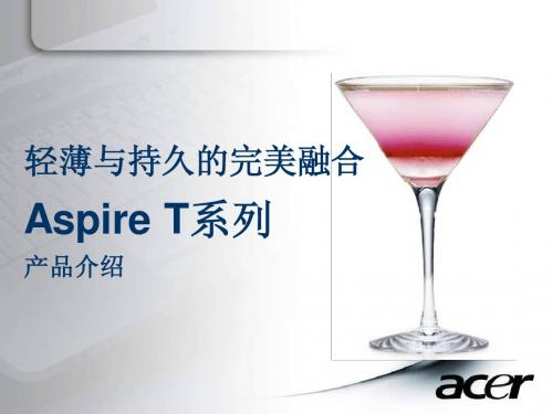
ACER T系列介绍

Aspire T系列 系列
产品介绍
AS T系列在 系列在Acer NB 系列在 消费产品线的定位
4810T
5810T
3810T
目标客户
全日工作(8小时以上 小时以上) 需要电脑全日工作 小时以上 的续航时间 因长时间使用 ,更需要 具有环保设计的产品
希望随处使用电脑 工作, 要求可靠性很高 工作 随时上网, 随时上网,沟通便捷 能满足大多数工作及一般 娱乐要求移动性强而非 图形性能 随时随地获取 最新鲜的资讯
30秒总结Aspire T系列 30秒总结Aspire
1:全球首款超长续航时间16:9“轻薄影院本”,轻松移动, 全球首款超长续航时间16: 16 轻薄影院本” 轻松移动, 轻松使用 2:多项节能技术造就8小时超长电池使用时间,连续使用不 多项节能技术造就8小时超长电池使用时间, 需充电, 需充电,外出工作娱乐更惬意 3:全系列产品最轻只有1.6公斤(含电池),最薄处只有2.34 全系列产品最轻只有1.6公斤(含电池) 最薄处只有2.34 1.6公斤 厘米,超级便携, 厘米,超级便携,轻薄移动 4:杜比二代标准听音室认证,配合高清超薄屏幕,轻松打 杜比二代标准听音室认证,配合高清超薄屏幕, 造个人的移动影院, 造个人的移动影院, 普通音响也能 欣赏震撼影音 5:制造材料严格遵守权威环保标准,确保能耗及污染降到 制造材料严格遵守权威环保标准, 最低,留下更多绿色, 最低,留下更多绿色,营造更多蓝天
• 摆脱电源插座的束缚 • 长效电力支持差旅途中的工作娱乐,尽享便捷
Acer节能软件轻松节能 Acer节能软件轻松节能
• 智能设定
一键式简化控制,即可通过Acer 节能键获得所需的 最佳工作方式,以获取最大的效能●
Philips EasySmart LED T8绿色智能灯泡说明书

TechnicalApplication GuidePhilips is now introducing a new line of connected LED lighting products with EasySmart technology. Philips InstantFit LED T8 with EasySmart technology is compatible with verified1 electronic ballasts. It is the easiest way to replace fluorescent lamps with connected LED lamps without rewiring the fixture. It is true plug and play. The lamp offers standard ZigBee based connectivity that easily interoperates with various control devices. Compared with a non-connected LED solution, EasySmart technology realizes more energy savings by enabling advanced control options.Product FeaturesBallast Compatibility•Innovative driver design that enables a “plug-and-play” LED solution•Compatible with verified1 electronic ballast•Quick and easy installationConnectivity•ZigBee based wireless interface•Reliable and secure wireless communication, nominal range 40 feet•Up to 50 lamps in one network•Easy commissioning and (re-)configuration from the floorControl Functionality•Automatic on/off and dimming based on occupancy detection and daylight variation•Personal dimming and scene setting with Zigbee wireless switch•High-end trimming to help save energy and extend lamp lifeEnergy Savings•Energy savings of 50% or more* when used with advanced control such as dimming, occupancy sensing and daylight harvesting.•DLC listed.User comfort•Uniform light output with advanced optical design.•Personal light setting to enhance user comfort and productivity•Typical CRI 82Reliability•Reliable operation between -20°C and +45°C ambient temperature.•Tested to B50 L70 requirement. Lamps are rated for 50,000 hours.•200,000 switching cycles.Safety•Over voltage and over temperature protection.•Complies with relevant UL and CSA safety requirements.•Shatterproof polycarbonate (PC) material.Environment•No Mercury.•Low Carbon Footprint.System OverviewCommunication between lamps, switch and sensors is ZigBee based.To facilitate the installation, Philips provides an IR tool as accessory. Your control device manufacturer will provide a tool (ie: mobile app) to commission the sensor and switch.* Philips InstantFit LED T8 with EasySmart technology uses ZigBee protocol to communicate with each other and 3rd party control devices.* IR programming tool communicates with individual lamp via infrared.* 50% energy savings compared to an F32T8 when dimmed at least 30% for 10% of the time product is on.ApplicationsSpectral Power DistributionPhotometric Diagrams1 x TLED 14W 3000K 160D 9290012811 1 x 2000 lm1 x TLED 14W 3500K 160D 9290012812 1 x 2000 lm1 x TLED 14W 4000K 160D 9290012813 1 x 2100 lm1 x TLED 14W 5000K 160D 9290012814 1 x 2100 lmLifetime and Lumen MaintenancePhilips InstantFit LED T8 with EasySmart technology has a lifetime of 50,000 hours. This is defined as the number of hours when 50% of a large group of identical lamps drops below 70% of its initial lumens.Lifetime and DimmingDimming can help extend lifetime (ie: dimming 30% can extend lifetime by 9,000 hours)Lifetime and Failure RateLifetime vs. Failure rate @T a 25°C Lifetime vs. Failure Rate vs. T caseTemperatureOperating Temperature T operating min -20°C max +45°C Storage Temperature T storage min -40°C max +65°C Maximum case temperature of tube atT case+37°CT amb=25°CDimensionsDimensions (mm)Product A1 A2 A3 D1D2 14T8/481198.11205.21212.325.627.8Technical Specs and Order information*test based on reference instant-start ballastPlease visit /EasySmart for latest information on ballast compatibility.Product DescriptionBare Lamp Watts* Average System Watts* Standby Power* Initial Lumens Lifetime (hrs) Cap Base Length (in) Bulb Type CCTRF RangeProduct number14T8/48-3000 IF 10/1 EasySmart 14W 16.5W <0.5W 2000lm 50,000 G13 48 T8 3000K 40ft 929001281104 14T8/48-3500 IF 10/1 EasySmart 14W 16.5W <0.5W 2000lm 50,000 G13 48 T8 3500K 40ft 929001281204 14T8/48-4000 IF 10/1 EasySmart 14W 16.5W <0.5W 2100lm 50,000 G13 48 T8 4000K 40ft 929001281304 14T8/48-5000 IF 10/1 EasySmart14W16.5W<0.5W2100lm50,000G1348T85000K40ft929001281404AccessoriesOrdering Code Product Number Product Description473504 929001390604 EasySmart IR Programming Tool 10/1Control CompatibilityPhilips InstantFit LED T8 with EasySmart technology now works with:Product DescriptionBrand Model ID/OrderCodeLeviton DLDNK-01W Intellect Decora Lumina RF 1-Button multi-function BLE keypad with room controller and LED feedbackfunctionality, 120-277VAC, 50/60Hz, WhiteLeviton DLDNK-02W Intellect Decora Lumina RF 2-Button multi-function BLE keypad with room controller and LED feedbackfunctionality, 120-277VAC, 50/60Hz, WhiteLeviton DLDNK-04W Intellect Decora Lumina RF 4-Button multi-function BLE keypad with room controller and LED feedbackfunctionality, 120-277VAC, 50/60Hz, WhiteLeviton DLDNK-08W Intellect Decora Lumina RF 8-Button multi-function BLE keypad with room controller and LED feedbackfunctionality, 120-277VAC, 50/60Hz, WhiteLeviton ZSC04-IxW Lumina RF PIR Occupancy Sensor, 450 sq ftLeviton ZSC15-IxW Lumina RF PIR Occupancy Sensor, 1,500 sq ftLeviton LURPC-00W Lumina RF Wireless PhotocellLeviton FREE Neuron AppProduct must be used with compatible control devices. Please visit /EasySmart for latest information on control compatibility.Approbation & CertificatesPhilips InstantFit LED T8 with EasySmart technology strictly follows applicable legislation and standard. The product complies with UL, CSA, NSF and RoHS.Product is DLC qualified:Philips is a member of ZigBee Alliance. Product is ZigBee certified.Application Notes•Product is dimmable by wireless control•Suitable for damp locations•Reliable operation between -20°C to + 45°C ambient temperature•Suitable to replace T8 fluorescent lamps that operate on instant-start ballasts. Please refer to /EasySmart for latest ballast compatibility list.•Require use of shunted lamp holders•Not intended for use in emergency luminaires•Not compatible with luminaires that use a remote starter•Modifications to the product void the limited warranty. For warranty information, please see /warranties•You are required to read and understand the Quick Installation Guide and all warnings, cautions and other materials related to installation published at: /EasySmart before commencing installation work.Footnotes1 Verified as compatible by Philips. Visit /EasySmart for latest ballast compatibility guide.。
智能光感恒照度LED灯管安装说明书

智能光感恒照度T8 LED 灯管安装说明书1.概述智能光感恒照度T8 LED 灯管,根据环境光的变化,控制LED 灯管的亮度,当照射面照度高于设置值时,降低LED 灯管的亮度,环境光高于设置值时,关闭LED 灯;当照射面照度低于于设置值时,增加LED 灯管的亮度,保证照射面得到恒定的照度。
用户可以根据不同环境的需求,现场设定照射面的照度值。
2. 技术指标型号 T8‐1200‐18‐L ‐01 T8‐1200‐24‐L ‐01 T8‐0600‐08‐L ‐01 T8‐0600‐12‐L ‐01 规格 T8 1200mm T8 1200mm T8 600mm T8 600mm 输入电压 AC200‐240V 50Hz AC200‐240V 50Hz AC200‐240V 50Hz AC200‐240V 50Hz 功率 18W (满功率时) 24W (满功率时) 8W (满功率时) 12W (满功率时) 功率因数PF >0.9(满功率时) >0.9(满功率时) >0.9(满功率时) >0.9(满功率时)色温 3000/4000/6000K 3000/4000/6000K 3000/4000/6000K 3000/4000/6000K 光通量1450/1600/1600lm2000/2200/2200lm600/700/700lm 950/1100/1100lm 照度设置范围 100‐500Lux 100‐500Lux 100‐500Lux 100‐500Lux 控制精度 ±10% ±10% ±10% ±10% 安装高度 MAX 5M MAX 5M MAX 5M MAX 5M 调光范围 0‐100% 0‐100% 0‐100% 0‐100% 工作温度 ‐25‐40℃ ‐25‐40℃ ‐25‐40℃ ‐25‐40℃ 外形尺寸 1212*29*33mm1212*29*33mm602*29*33mm602*29*33mm3.接线图请严格按照接线图接线,灯管可适用电感镇流器线路,必须取下启辉器;灯管不适用电子镇流器。
8M20 系列机芯 维修手册

/bbs.php 2
器 电 成 添
简要说明: 1、5VST 为待机 5V 正常工作为 520MA 左右; 2、12V 除以上供电以外还提供给预中放、TCON、通过 7805 转化为 5V 提供给高频头、 转化成 33V 给高频头供电; 3、待机后 12V 大约 4V 左右;
/bbs.php
器 电 成 添
典型应用电路:
图二
输出电压计算公式 Vo=0.92v*(1+R1/R2),可根据此获得向要输出的电压值
控制信号的输入和输出
温馨提示 :由于某些控制信 号后级加有反相 电路等,以下说明 的高低电平均是 指
主芯片的引脚端电压值。
AMS1117-3.3
4
U6 MST6M16JS L48=NC,U6=1117
IN OUT AD J
3
2
1
+3.3AVDD L48
+3.3Vstb
+5V
C33
C385 C34 C386 C388
NC
0.1uF
10uF 0.1uF 2.2uF
NC/10UF
12V 通过 MPS1482 转化为 5V,通过 AMS1117 转化为 3.3V/2.6 提供给 6M16 及 DDR 供电。
☆ HDMI_HOUPLUG(PIN10 PIN214),当插入 HDMI 信号线且主芯片检测到 HDMI 的
信号时,此引脚输出一个高电平;
/bbs.php
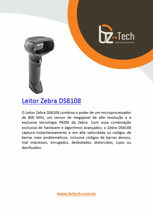
斑马技术公司DS8108数字扫描仪产品参考指南说明书

TA8210AH

TOSHIBA Bipolar Linear Integrated Circuit Silicon MonolithicTA8210AH,TA8210AL20W BTL × 2ch Audio Power AmplifierThe thermal resistance θj −T of TA8210AH, TA8210AL package designed for low thermal resistance, has a high efficiency of heat radiation.The temperature rise of chip can be reduced, and the influence from the degradation of the features due to the temperature rise at the high output can also be reduced.This stereo audio power IC, designed for car audio use, has two built −in channels to reduce the characteristic difference between L and R channels.In addition, the functions of stand −by and muting, and a variety of protection circuits are involved.Features· Low thermal resistance: θj −T = 1.5°C / W (infinite heat sink) · High power: P OUT (1) = 22W (typ.) / channel(V CC = 14.4V, f = 1kHz, THD = 10%, R L = 4Ω) P OUT (2) = 19W (typ.) / channel(V CC = 13.2V, f = 1kHz, THD = 10%, R L = 4Ω)· Low distortion ratio: THD = 0.04% (typ.) (V CC = 13.2V, f = 1kHz, P OUT = 1W, R L = 4Ω, G V = 50dB) · Low noise: V NO = 0.30mV rms (typ.) (V CC = 13.2V, R L = 4Ω, G V 50dB, R g = 0Ω, BW = 20Hz~20kHz) · Built −in stand −by function (with pin(4) set at low, power is turned off.): I SB = 1µA (typ.) · Built −in muting function (with pin(1) set at low, power is turned off.): V (mute) = 1V (typ.) ·Built −in various protection circuitsProtection circuits: Thermal shut down, Over voltage, Out →V CC short, Out →GND short and Out −Out short. · Operating supply voltage: V CC = 9~18VWeightHZIP17−P −2.00: 9.8g (typ.) HSIP17−P −2.00: 9.8g (typ.)Block DiagramTA8210AH, TA8210AL (G V = 50dB)Cautions And Application Method(description is made only on the single channel.)1. Voltage gain adjustmentThis IC has the amplifier construction as shown in Fig.1. The pre-amp (amp 1) is provided to the primary stage, and the input voltage is amplified by the flat amps, amp 3 and amp 4 of each channel through the phase amp. (Amp 2).Since the input offset is prevented by pre-amp when V CC is set to on, this circuit can remarkably reduce the pop noise.The total closed loop gain G V of this IC can be obtained by expression below when the closed loop voltage gain of amp 1 is G V 1.(dB) R2f R R2)f (R R1 og 20 V1G +++=l (1)The closed loop voltage gain of power amp, amp 3 and amp 4 is fixed at G V3≒G V4 = 20dB.Therefore, the total closed circuit voltage gain G V is obtained through BTL connection by the expression below. G V = G V 1 + G V3 + 6 (dB) (2)For example, when R f = 0Ω, G V is obtained by the expressions (1) and (2) as shown below. G V ≒24 + 20 + 6 = 50dBThe voltage gain is reduced when R f is increased. (Fig.2) With the voltage gain reduced, since (1) the oscillation stability is reduced, and (2) the pop noise changes when V CC is set to on, refer to the items 3 and 4.Fig.22. Stand -by SW functionBy means of controlling pin(4) (stand -by terminal) to high and low, the power supply can be set to on and off. The threshold voltage of pin(4) is set at 2.1V (3V BE .), and the power supply current is about 1µA (typ.) at the stand -by state.Pin(4) control voltage : V (SB)Stand -by Power V (SB) (V)On Off 0~2 Off On 3~V CCFig.3 With pin(4) set to high, power is on.Advantage of stand -by SW (1) Since V CC can directly be controlled to on / off by the microcomputer, the switching relay can be omitted. (2) Since the control current is microscopic, the switching relay of small current capacity is satisfactory forswitching.3. Preventive measure against oscillationFor preventing the oscillation, it is advisable to use C4, the condenser of polyester film having small characteristic fluctuation of the temperature and the frequency.The resistance R to be series applied to C4 is effective for phase correction of high frequency, and improves the oscillation allowance.Since the oscillation allowance is varied according to the causes described below, perform the temperature test to check the oscillation allowance.(1) Voltage gain to be used (G V setting)(2) Capacity value of condenser(3) Kind of condenser(4) Layout of printed boardIn case of its use with the voltage gain G V reduced or with the feedback amount increased, care must be taken because the phase-inversion is caused by the high frequency resulting in making the oscillation viably generated.4. Input offset prevention circuit at V CC→onHaving Pre-Amp (Amp 1) mounted on the primary stage, this IC contains the circuit for making the Amp 1 input voltage and the NF terminal voltage equipotential.Therefore, the offset voltage produced at the input stage is suppressed to prevent the pop noise at V CC→on. The capacity values of the input and NF condenser (C1 and C2) shall be set according to the gain to be used. (Reference) (A) At G V = 50dB (R f = 0Ω)C1 = 4.7µF, C2 = 47µF(B) At G V = 40dB (R f = 470Ω)C1 = 3.3µF, C2 = 33µF5. Muting functionThrough setting pin(1) (mute terminal) at about 1V or less, muting becomes possible.The interval circuit of IC is shown in Fig.4.When pin(1) is set to low, Q1 and Q2 are turned to on, the charge of the ripple condenser is discharged and the bias is cut. The mute amount of 60dB or over can be obtained.Since this muting function rapidly discharge the charge of the ripple filter capacitor of pin(8), the pop noise is generated by the DC fluctuation of the bias section.Therefore, this muting function is not appropriate to the audio muting but it is effective in muting at V CC→on.Maximum Ratings (Ta = 25°C)Characteristic Symbol Rating UnitPeak supply voltage (0.2s) V CC (surge)50VDC supply voltage V CC (DC) 25 V Operating supply voltage V CC (opr) 18 V Output current (peak) I O (peak) 9 A Power dissipation P D 50 W Operating temperature T opr -30~85 °C Storage temperatureT stg-55~150 °CElectrical Characteristics(unless otherwise specified, V CC = 13.2V, R L = 4Ω, f = 1kHz, Ta = 25°C)Characteristic SymbolTest Cir -cuitTest ConditionMin.Typ.Max.Unit Quiescent supply current I CCQ ― V IN = 0― 120 250mA P OUT (1) ― V CC = 14.4V, THD = 10% ― 22 ― Output powerP OUT (2) ― THD = 10% 1619―WTotal harmonic distortion THD ― P OUT = 1W― 0.04 0.4 % Voltage gain G V ― ―48 50 52 dB Output noise voltage V NO ― R g = 0Ω,BW = 20Hz~20kHz ― 0.30 0.70mV rmsRipple rejection ratio R.R. ― fripple = 100Hz, R g = 600Ω40 54 ― dB Input resistance R IN ― ― ― 30 ―k ΩOutput offset voltage V offset ― V IN = 0-0.3 0 0.3 mV Current at stand −by state I SB ― ―― 1 10 µA Cross talkC.T.―R g = 600Ω,V OUT = 0.775V rms (0dBm) ― 60 ― dBPni(4) control voltage V SB ― Stand -by →off (power →on) 2.5 ―V CCVPin(1) control voltageV (mute)―Mute →on (power →off) ― 1.0 2.0 VTest CircuitTA8210AH, TA8210AL (G V = 50dB)Package DimensionsWeight: 9.8g (typ.)Package DimensionsWeight: 9.8g (typ.)· TOSHIBA is continually working to improve the quality and reliability of its products. Nevertheless, semiconductor devices in general can malfunction or fail due to their inherent electrical sensitivity and vulnerability to physical stress. It is the responsibility of the buyer, when utilizing TOSHIBA products, to comply with the standards of safety in making a safe design for the entire system, and to avoid situations in which a malfunction or failure of such TOSHIBA products could cause loss of human life, bodily injury or damage to property.In developing your designs, please ensure that TOSHIBA products are used within specified operating ranges as set forth in the most recent TOSHIBA products specifications. Also, please keep in mind the precautions and conditions set forth in the “Handling Guide for Semiconductor Devices,” or “TOSHIBA Semiconductor Reliability Handbook” etc..· The TOSHIBA products listed in this document are intended for usage in general electronics applications (computer, personal equipment, office equipment, measuring equipment, industrial robotics, domestic appliances, etc.). These TOSHIBA products are neither intended nor warranted for usage in equipment that requires extraordinarily high quality and/or reliability or a malfunction or failure of which may cause loss of human life or bodily injury (“Unintended Usage”). Unintended Usage include atomic energy control instruments, airplane or spaceship instruments, transportation instruments, traffic signal instruments, combustion control instruments, medical instruments, all types of safety devices, etc.. Unintended Usage of TOSHIBA products listed in this document shall be made at the customer’s own risk.· The products described in this document are subject to the foreign exchange and foreign trade laws.· The information contained herein is presented only as a guide for the applications of our products. No responsibility is assumed by TOSHIBA CORPORATION for any infringements of intellectual property or other rights of the third parties which may result from its use. No license is granted by implication or otherwise under any intellectual property or other rights of TOSHIBA CORPORATION or others.· The information contained herein is subject to change without notice.000707EBA RESTRICTIONS ON PRODUCT USEThis datasheet has been download from: Datasheets for electronics components.。
Bosch 产品说明书.pdf_1702041417.9129715

623.5
Capacity
Number of place settings 15
Technical Details
Watts (W)
1440 W
Current (A)
12 Amps
Volts (V)
120 V
Frequency (Hz)
60 Hz
Power cord length
67"
- Install length from corner of unit
Warranties: Please see Use & Care manual or Bosch website for statement of limited warranty.
For more information on our entire line of products, go to /us or call 1-800-944-2904
© BSH Home Appliances Corporation. All rights reserved. Bosch is a registered trademark of Robert Bosch GmbH.
06/19
24" Custom Panel ADA Compliant Dishwasher
Notes: All height, width and depth dimensions are shown in inches. BSH reserves the absolute and unrestricted right to change product materials and specifications, at any time, without notice. Consult the product’s installation instructions for final dimensional data and other details prior to making cutout.
