Asymmetrical two-atom entanglement in a coated microsphere
单斜相阿利特的晶体结构研究(英文)

Recent work have concerned the identification of stabilized modifications at room temperature due to the importance in the quality control of Portland cement. Differential thermal analysis (DTA) showes the T1–T2 transi-
The objective of this paper was to describe the superstructures of the monoclinic modification of C3S. Some indices for describing the reflections due to the superstructures were proposed to express the orientations and
1 Experimental
The specimens were provided by China Building Materials Academy (CBMA). A selected-area electron diffraction (SAED) technique was applied to record the reflections. A TEM device (Model JEM–2010UHR, JEOL, Tokyo, Japan) equipped with a double tilt goniometry was used to record the HRTEM images at an accelerating voltage of 200 kV. The preparation of specimens for the TEM was performed by a conventional method applied for the observation of ceramic powders except for the dispersion of the specimens in ethanol. Table 1 shows the chemical compositions of the specimens, which was provided by the CBMA. The three specimens are remarked as A, B, and C.
零维锑基有机-无机杂化氯化物的自陷态激子发光及其发光二极管

第43卷㊀第1期2022年1月发㊀光㊀学㊀报CHINESE JOURNAL OF LUMINESCENCEVol.43No.1Jan.,2022文章编号:1000-7032(2022)01-0094-09㊀㊀收稿日期:2021-10-06;修订日期:2021-10-25㊀㊀基金项目:国家自然科学基金(11904345,61905230,52072355,52103241);浙江省自然科学基金(LQ19F040004)资助项目Supported by National Natural Science Foundation of China(11904345,61905230,52072355,52103241);Natural Science Foun-dation of Zhejiang Province(LQ19F040004)零维锑基有机-无机杂化氯化物的自陷态激子发光及其发光二极管蔡培庆1∗,滕嵘驭1,张㊀帝1,王㊀淞1,占宇鑫1,王祥夫2∗,司俊杰1,姚㊀鑫1,艾㊀琦1,刘祖刚1∗(1.中国计量大学光学与电子科技学院,浙江杭州㊀310000;2.南京邮电大学电子与光学工程学院,微电子学院,江苏南京㊀210023)摘要:新兴的零维金属卤化物材料由于其优异的光电性能,近期引起了研究者们的特别关注㊂本文使用反溶剂法和旋涂法分别制备了零维金属卤化物四苯基膦氯化锑[(C 6H 5)4P]2SbCl 5的发光材料和器件,通过稳态激发/发射光谱㊁瞬态光谱对其发光性能进行了研究㊂研究结果表明,在紫外光激发下,[(C 6H 5)4P]2SbCl 5可以发出明亮的橙红光,这种橙红光源于零维限域作用下的自陷态激子三重态发光㊂变温光致发光(PL)和衰减寿命研究表明该物质具有600meV 左右的热激活能,抗热猝灭性能较强㊂通过优化器件结构,引入聚[双(4-苯基)(4-丁基苯基)胺](Poly-TPD )作为空穴传输层,通过混合Poly-TPD 的荧光发射和[(C 6H 5)4P]2SbCl 5的自陷激子发光,获得了在6V 偏压下126cd /m 2的暖白光电致发光器件㊂本工作对溶液法加工无铅金属卤化合物电致发光器件的进程具有一定的推动作用㊂关㊀键㊀词:零维发光材料;自陷态激子;电致发光中图分类号:O482.31;TN383+.1㊀㊀㊀文献标识码:A㊀㊀㊀DOI :10.37188/CJL.20210318Self-trapped Exciton Luminescence and Light-emitting-diodes Based onZero-dimensional Organic-inorganic Hybrid Antimony ChlorideCAI Pei-qing 1∗,TENG Rong-yu 1,ZHANG Di 1,WANG Song 1,ZHAN Yu-xin 1,WANG Xiang-fu 2∗,SI Jun-jie 1,YAO Xin 1,AI Qi 1,LIU Zu-gang 1∗(1.College of Optical and Electronic Technology ,China Jiliang University ,Hangzhou 310000,China ;2.College of Electronic and Optical Engineering and College of Microelectronics ,Nanjing University of Posts and Telecommunications ,Nanjing 210023,China )∗Corresponding Authors ,E-mail :pqcai @ ;xfwang @ ;zgliu 78@Abstract :The emerging of the zero-dimensional metal halide materials has attracted great attention of researchers due to their excellent photoelectric properties.Herein,the luminescent material and device based on zero-dimensional metal halide tetraphenylphosphoniumantimony chloride[(C 6H 5)4P]2SbCl 5were prepared by anti-solvent method and spin-coating method,respectively.The optoelectronic properties of [(C 6H 5)4P]2SbCl 5were investigated by excitation spectra,emis-sion spectra,and time-resolved spectra.The results show that [(C 6H 5)4P]2SbCl 5can emit bright orange-red emission under the ultraviolet excitation.This orange-red emission originates from the triplet self-trapped exciton induced by the zero-dimensional spatial confinement.Temperature. All Rights Reserved.㊀第1期蔡培庆,等:零维锑基有机-无机杂化氯化物的自陷态激子发光及其发光二极管95㊀dependent PL and decay lifetime studies reveal that the material has a thermal activation energy withthe value of~600meV,thus it has favorable anti-thermal quenching effect.By optimizing the de-vice structure and introducing poly[bis(4-phenyl)(4-butylphenyl)amine](Poly-TPD)as a hole transport layer,the warm white emission by mixing the fluorescence emission of Poly-TPD and the self-trapped exciton emission of[(C6H5)4P]2SbCl5was obtained with a brightness of126cd/m2 under a bias of6V.This work provides an alternative approach for the development of the manufac-ture of lead-free metal halide electroluminescent devices by solution method.Key words:zero-dimensional luminescent material;self-trapped exciton;electroluminescence1㊀引㊀㊀言铅基金属卤化物钙钛矿材料由于具有优异的光电性能,近年来引起了广大研究者的关注[1-5]㊂然而,其中存在的可溶性重金属铅元素对人体健康存在隐患,因此无铅金属卤化物材料逐渐成为研究热点㊂目前,人们已经开发出多种具有较高能量转化效率的全无机无铅金属卤化物材料和有机-无机杂化金属卤化物光电材料,并研究了这些材料在紫外光探测[6]㊁X射线成像[7]㊁太阳能电池[8]㊁照明与显示[9]等领域的应用㊂在无铅金属卤化物材料中,零维金属卤化物材料具有多变的空间几何特性和独特的电子结构,因此,关于该类化合物的光致发光研究已有大量的文献见诸报道,华南理工大学夏志国教授近期综述了该领域的进展[10-11]㊂零维金属卤化物发光材料的发光来源主要有两大类㊂一类是孤立发光中心的发光,如掺杂于其中的稀土离子或者过渡金属离子;另一类是由零维金属卤化物的晶格受到光照或者偏压等诱导产生变形和极化,由此产生的束缚自陷态激子(Self-trapped exciton, STE)发光,属于复合发光的范畴㊂近期,该类STE发光现象引起了大量研究者的关注[12-14]㊂零维金属卤化物材料的自陷态激子发光一般有如下特点:(1)由于空间位置的限域特性和三维空间内较强的介电屏蔽作用,激子的扩散距离往往较短,体现出类似于弗兰克尔激子和空间转移激子的特性;(2)激发态下的激子由于受晶格的束缚,电子-晶格耦合作用较强,具有较大的弗兰克-康登因子(Frank-Condon-factor),发光峰型较宽,斯托克斯位移一般较大,光子循环作用较弱,量子产率较高;(3)由于自陷态激子受零维金属卤化物中存在的卤素和金属的重原子效应影响,自旋-轨道耦合作用较为明显,因此一般呈现出微秒级别的三重态自陷激子磷光寿命㊂然而,目前关于自陷态激子电致发光(Electroluminescence,EL)现象的报道较少,主要有CsPbI3体系[15-17]㊁Cs2AgInCl6体系[18]㊁Cs3Cu2I5/CsCu2I3体系[19-22],以及本课题组报道的二维钙钛矿体系[23]等㊂因此,开拓出新型基于自陷态激子发光的电致发光器件对金属卤化物光电器件的无铅化研究非常重要㊂芳香膦(氧)基团由于结构上打破共轭,可以同时调控电子效应和空间效应,因此非常适合用于构建综合性能优异的电致发光材料和器件㊂黑龙江大学许辉教授在该方面有综合性的评述[24]; 2017年,福建物构所陈忠宁研究员报道了基于四苯基膦溴化锰的绿光电致发光器件,最高外量子效率可达10.49%[25];2018年,Ma等报道了光致发光量子效率接近100%的四苯基膦氯化锑橙光材料[26]㊂因此,通过芳香膦基无铅金属配合物获得高效电致发光器件是实现无铅化器件的可行途径之一㊂本文通过反溶剂结晶的方法,合成出具有较高发光强度的零维四苯基膦氯化锑[(C6H5)4P]2SbCl5 (以下缩写为TPP2SbCl5)材料,对其发光性质进行了研究㊂并通过溶液加工和真空镀膜等工艺,成功制备出基于自陷态激子的暖白光电致发光器件㊂2㊀实㊀㊀验2.1㊀样品制备粉末样品的制备:首先将四苯基氯化膦(C6H5)4PCl(阿拉丁,98%)和三氯化锑SbCl3(阿拉丁,99.98%)按2ʒ1的量比称取样品,溶于二甲基亚砜DMSO(阿法埃莎,99.9%)溶液中;然后将装有DMSO溶液的5mL小瓶置于盛有10mL乙. All Rights Reserved.96㊀发㊀㊀光㊀㊀学㊀㊀报第43卷醚(国药,分析纯)的50mL烧杯中,将烧杯的开口塑封;通过乙醚的反溶剂作用,静置一周左右可析出大量白色沉淀,将产生的白色沉淀离心并置于130ħ的真空干燥箱内干燥过夜,所得粉末产物即为最终产物TPP2SbCl5㊂薄膜样品的制备:在充满氮气的手套箱中使用DMSO和N,N-二甲基甲酰胺DMF(阿法埃莎, 99.9%)溶解上述获得的白色产物,然后将溶液旋涂在洁净的石英片上,将石英片置于120ħ的热台上退火,获得薄膜样品㊂2.2㊀器件制备将ITO玻璃基片依次使用洗涤剂Decon90 (英国迪康)㊁丙酮(国药,分析纯)㊁超纯水㊁异丙醇(国药,分析纯)等超声清洗,氮气吹干并用等离子体清洗机处理后备用㊂在空气氛围中,以3000r/min的转速旋涂空穴注入层聚3,4-乙烯二氧噻吩/聚苯乙烯磺酸盐PEDOTʒPSS(西安宝莱特)于ITO玻璃基片上, 110ħ退火10min,然后将基片转移至氮气手套箱内,再次旋涂空穴传输层聚[双(4-苯基)(4-丁基苯基)胺]Poly-TPD(西安宝莱特,M nȡ60000)的氯苯(阿法埃莎,99.9%)溶液,120ħ退火10 min㊂然后在基片上旋涂含有TPP2SbCl5的DMSO 溶液,并经过120ħ退火30min处理㊂将处理后的基片转移至真空蒸镀镀膜机中,在真空度降低至5.33ˑ10-4Pa(4ˑ10-6torr)后,分别蒸镀电子传输层材料1,3,5-三(1-苯基-1H-苯并咪唑-2-基)苯TPBi(西安宝莱特,99.9%)㊁电子注入层LiF(中诺新材,99.99%)和金属Al(中诺新材, 99.999%)电极,最后使用紫外固化胶(乐泰3492)和玻璃盖板完成对器件的封装,用于下一步的器件测试㊂2.3㊀表征手段使用德国Bruker D8型X射线衍射仪测量粉末和薄膜的物相信息;利用爱丁堡稳态瞬态荧光光谱仪FLS1000测量样品的光谱数据;稳态光源选用的是欧司朗除臭氧的450W氙灯,稳态激发光谱(Photoluminescence excitation,PLE)和发射光谱(Photoluminescence emission,PL)数据分别经过爱丁堡FLS1000内置的氙灯谱线参考文件和滨松R928P型光电倍增管(Photomultiplier tube,PMT)矫正文件进行矫正;瞬态光谱测试使用爱丁堡375nm皮秒脉冲激光器作为光源,利用单光子计数技术测量荧光衰减曲线㊂通过东方晨景NCV30-2W-H型液氮低温恒温器控制样品的测试温度㊂使用耐驰STA449F3同步热分析仪进行热重分析,使用台阶仪(美国KLA Alpha-Step D-500)测试器件各功能层的厚度㊂利用Thermo ES-CALAB XI光电子能谱仪测量紫外光电子能谱(Ultroviolet photoelectron spectrometer,UPS)㊂采用Keithley2400电流-电压源表㊁硅光电探头和PR670光度计构成的测试系统测量电流(I)-电压(V)-亮度曲线和外量子效率(External quantum ef-ficiency,EQE)㊂3㊀结果与讨论3.1㊀TPP2SbCl5的室温光致发光和结构性质分析图1(a)是粉末样品的发射光谱和激发光谱㊂激发光谱表明TPP2SbCl5可以在260~410nm左右的紫外区域内被有效激发,光谱在紫外区的强度分布较为平坦,没有明显的锐线激子特征峰出现,激发峰边在370nm左右以后快速变陡,以上特征表明该物质具有基质晶格吸收特性㊂由于本实验中使用的激发光源为除臭氧型氙灯,光源在高于260nm以上的紫外区域内强度较弱,因此无法探测该物质在真空紫外区的激发情况,相关性能后期可以通过真空紫外光谱技术研究㊂另外,已有报道表明有机无机杂化卤化物的自陷态激子可以被X射线等高能射线有效激发[27],因此,该类物质也可能有着良好的闪烁性能,相关性能有待进一步研究㊂发射光谱显示该物质的发射峰值在700nm 左右,为一宽带发射,可以将其归于自陷态激子的发射;发射光谱与激发光谱有着较大的斯托克斯位移,表明该物质的发光可以用强耦合模型的位型坐标图去解释㊂由于滨松R928P型PMT的探测范围限制,800nm以后的发射区域噪声过大,因此超过800nm的光谱区域并未扫谱㊂图1(a)中插图显示,该粉末在日光照射下为一白色物质,表明其在可见光区没有吸收;在365nm的紫外灯激发下,该粉末发射出肉眼可见的明亮的橙红光,但这与实测发射光谱峰值位于700nm是不一致的㊂该现象可以解释如下:由于该物质在500~ 900nm左右均有非常强的宽带发射,但人眼对680nm以上的深红光不敏感,所以人眼观测到该. All Rights Reserved.㊀第1期蔡培庆,等:零维锑基有机-无机杂化氯化物的自陷态激子发光及其发光二极管97㊀图1㊀(a)TPP2SbCl5粉末的激发/发射光谱,激发光谱的监测波长为700nm,发射光谱的激发波长为365nm,插图从左到右分别为粉末样品在日光下㊁在365nm紫外灯激发下以及在365nm紫外灯激发下通过650nm长波通滤波片拍摄的照片;(b)TPP2SbCl5粉末和薄膜的发射光谱对比,插图自上往下分别为在365nm紫外灯激发下,使用DMSO㊁DMF旋涂的TPP2SbCl5薄膜,以及TPP2SbCl5粉末的荧光照片;TPP2SbCl5粉末和薄膜的XRD图谱(c)和结构图(d)㊂Fig.1㊀(a)Excitation and emission spectra of TPP2SbCl5,where the excitation wavelength of PL spectrum is365nm,and the monitoring wavelength of PLE spectrum is700nm,the inserts,from left to right,show the photographs of the powder sample under sun light,365nm UV excitation and365nm UV excitation with650nm long-pass filter,respectively.(b) PL spectra comparation of TPP2SbCl5powder and films,the inserts,from top to bottom,show the photographs under365 nm UV excitation of the TPP2SbCl5films spin-coated by DMSO and DMF solution and the TPP2SbCl5powder,respectively.(c)XRD data of TPP2SbCl5powder and film.(d)Crystal structure of TPP2SbCl5.物质的发光为橙红光㊂另外,如图1(a)中插图所示,通过透过650nm的长波通滤波片观察,我们可以确认该物质存在深红光区域的发射,这也意味着该物质在植物生长补光领域有着潜在的应用[28]㊂如图1(b)所示,TPP2SbCl5的粉末PL谱与使用DMSO㊁DMF溶液旋涂的薄膜PL谱相比,谱线有所不同㊂Ma等在制备该样品时发现了类似的现象㊂他们认为,由于金属卤化物自陷激子的荧光性质强烈依赖于软晶格的结构变化,这种自陷激子荧光发射的差异是由不同的残留有机溶剂分子导致材料热力学稳定相的转变造成的㊂研究发现,快速结晶的小颗粒薄膜样品为热力学不稳定相,薄膜的荧光呈现黄色;而缓慢结晶的大块样品是热力学稳定相,其荧光则红移至红色[26,29]㊂图1(b)插图的薄膜样品图片显示,使用DMSO旋涂而成的薄膜较为光滑,表明晶体颗粒较小;而用DMF旋涂而成的薄膜较为粗糙,表明晶体颗粒较大㊂在365nm紫外光激发下,DMSO和DMF作为溶剂旋涂的TPP2SbCl5薄膜发射峰值分别在635nm和660nm左右,粉末的发射峰值在705nm左右,随着颗粒的增大,光谱逐渐红移㊂因此,我们的实验结果与他们的结论符合得很好㊂如图1(c)所示,粉末和薄膜的XRD衍射测试结果表明,粉末的衍射图谱与已报道的TPP2SbCl5结构计算所得的衍射数据相匹配㊂但是,薄膜样品由于旋涂的厚度较薄(台阶仪测得约60nm),因此X射线衍射峰的强度较弱,图谱. All Rights Reserved.98㊀发㊀㊀光㊀㊀学㊀㊀报第43卷显示的仅为玻璃片的背景峰㊂图1(d)是TPP2SbCl5的结构示意图㊂如图所示,该物质属于三斜晶系的P1空间群,每个SbCl2-5阴离子基团均被四苯基膦大阳离子分隔开,形成具有较大空间位阻的零维结构㊂由于有机组分和无机组分的介电常数差异较大,这样的结构可阻碍激子的有效扩散范围,促进光生载流子自陷在SbCl2-5阴离子基团周围,增强自陷态激子的复合,最终导致高效的激子发射㊂3.2㊀TPP2SbCl5的变温光致发光分析变温荧光性质的分析可以探究TPP2SbCl5激发态的一些性质㊂图2(a)是TPP2SbCl5粉末从80~470K的变温荧光光谱㊂可以看到,荧光强度在室温以下温区的变化不太明显,但随着温度升高至高于室温的温区,荧光强度呈现大幅度下降的趋势,这与有机分子在室温以上的分子振动增强有关㊂图2(c)的热重分析表明,在80~470 K内,样品的重量并没有明显的变化,因此荧光强度的降低不是由于样品受热分解造成的㊂图2(b)是TPP2SbCl5粉末的变温荧光寿命图谱㊂在80~470K的测试温区内,该样品的自陷激子态发光均呈现出单指数衰减,并随着温度升高至室温左右,寿命开始大幅降低㊂上述现象表明,在这种零维限域结构的有机金属卤化物内,自陷态激子复合发光衰减是一个单分子过程,并且该过程受无辐射弛豫的影响较为明显[30-32]㊂另外,无论是在液氮温度或是470K左右的高温下,该物质的发光始终保持在时间较长的微秒量级(5.741~ 0.289μs),说明该物质的发光源于自陷激子的三重态禁阻发射[33]图2㊀TPP2SbCl5粉末的变温荧光光谱(a)和荧光衰减寿命(b);(c)TPP2SbCl5粉末的热重分析图;(d)~(e)荧光积分强度和荧光衰减寿命随着温度变化的计算结果和拟合曲线;(f)强耦合作用下的STE发光位型坐标模型图㊂Fig.2㊀Temperature dependent PL spectra(a)and decay curves of TPP2SbCl5powder(b).(c)TG curve of the TPP2SbCl5pow-der.(d)-(e)Integrated intensity of PL and lifetime values as a function of temperature,respectively.(f)Configuration coordinate diagram of STE luminescence under strong-coupling regime.通过以上荧光光谱和衰减寿命的分析,我们认为该物质的发光特征符合黄昆用于解释F色心发光行为的高温强耦合无辐射跃迁理论[34],可用如图2(f)所示的位型-坐标模型去解释㊂根据该理论的推导结果,不同温度下的荧光积分强度I(T)和荧光衰减寿命τ(T)随着温度T的变化符合如下公式[35]:I(T)=I01+A exp(-ΔE/kT),(1)τ(T)=τr1+(τr/τnr)exp(-ΔE/kT),(2)其中I0是绝对零度时的发光强度积分,A是前因子,τr是辐射跃迁寿命,τnr是非辐射跃迁寿命,ΔE是热激活能,k是玻尔兹曼常数㊂图2(d)㊁(e)是分别对I(T)和τ(T)随着T的变化拟合获得的结果㊂拟合获得的ΔE值分别为608meV和603meV,两种拟合方式获得的ΔE误差值较小,表明实验与理论符合得非常好㊂与室温相对应的热能. All Rights Reserved.㊀第1期蔡培庆,等:零维锑基有机-无机杂化氯化物的自陷态激子发光及其发光二极管99㊀(~26meV)相比,600meV左右的热激活能较大,因此这是零维TPP2SbCl5的自陷态激子在室温下没有热解离并能保持接近100%荧光量子效率的原因之一[26]㊂3.3㊀电致发光器件的构筑和发光分析通过UPS测试和吸收光谱计算,我们确定了如图3(c)所示的器件结构图,并经过逐层和多次的正交参数调控和优化,制备出以TPP2SbCl5为发光层的电致发光EL器件,器件参数为ITO/PEDOTʒPSS(40 nm)/Poly-TPD(30nm)/TPP2SbCl5(60nm)/TPBi(50 nm)/LiF(1.5nm)/Al(100nm)㊂图3(a)是该器件的I-V-L曲线,从图中可以看出器件的启亮电压为3.2V,在6V电压下,器件亮度达到126cd/m2㊂图3(b)展示了该器件外量子效率EQE与器件电流密度的函数曲线㊂数据结果表明,器件的最高EQE为0.39%㊂图3(d)为Poly-TPD/TPP2SbCl5薄膜的归一化PL光谱及器件EL的对比,可以看出器件的蓝光发射来源于空穴传输层的Poly-TPD发光,橙光来源于TPP2SbCl5的自陷态激子发光㊂但是, TPP2SbCl5的EL光谱与PL光谱相比在高能区和低能区均变窄㊂我们经分析认为,影响峰型窄化的因素如下:(1)首先,从能级的角度来看,无论是光致发光还是电致发光,Kasha规则确保光子必须在最低激发态下发射,自陷态激子发生T2ңS0辐射复合造成高能区一侧谱线变宽的可能性很小;(2)振动辅助的辐射跃迁(Vibration assisted radiative transition)几率降低可以导致谱线窄化㊂在PL过程和EL过程中,一些在PL过程中允许的振动辅助跃迁在EL过程中很可能是禁阻的,载流子在STE T1和S0的振动能级上复合的几率存在差异;在偏压作用下,分子的刚性增强也可能会导致振动减弱,导致STE EL光谱窄化㊂图3㊀(a)器件的I-V-L曲线;(b)器件的EQE与电流密度函数曲线;(c)器件的能级结构图;(d)Poly-TPD/TPP2SbCl5薄膜PL谱及器件EL谱比较;(e)不同电压下的器件EL谱;(f)不同电压下的CIE坐标,插图为器件在6V电压下的照片㊂Fig.3㊀(a)I-V-L curves of the prepared device.(b)EQE data of the device as a function of the current density.(c)Energy level structure of the device.(d)Comparation of the PL spectrum of the Poly-TPD/TPP2SbCl5film and the device EL spectrum.(e)EL spectra of the device at different applied bias.(f)CIE coordination at different applied voltages,the insert is the photograph of the device operated at6V.不同电压下的器件EL谱(图3(e))表明,随着电压的增大,蓝光部分逐渐增强,器件运行的视频请见本文的补充文件㊂图3(f)的CommissionInternationale de L Eclairage(CIE)1931图更加明显地显示了不同电压下色坐标的变化㊂从图3(c)的器件结构能级图中可以看出,该器件空穴传输层最低占据轨道(Lowest unoccupied molecu-lar orbital,LUMO)能级与发光层LUMO能级差较小(0.16eV),无法有效阻挡电子,而电子传输层最高占据轨道(Highest occupied molecular orbital,. All Rights Reserved.100㊀发㊀㊀光㊀㊀学㊀㊀报第43卷HOMO)能级和发光层HOMO 能级的能级差较大(0.72eV),阻挡空穴效果较好㊂因此,器件在工作过程中电子与空穴并未达到注入平衡㊂随着电压增大,更多的电子到达空穴传输层Poly-TPD 处,导致Poly-TPD 蓝光增强[36]㊂另外,如图3(f)插图所示,器件在6V 正置偏压下可发出明亮的暖白光,色坐标为(0.36,0.31),表明该器件在无铅金属卤化物白光照明上有着潜在的应用㊂图4为器件在较低电流密度20mA /cm 2下亮度随时间变化的老化测试㊂其在初始亮度110cd /cm 2下的T 90为5min,器件的稳定性能有待进一步改善㊂㊀图4㊀器件在20mA /cm 2电流密度下亮度随时间的变化Fig.4㊀The luminance of the device as a function of time un-der a constant driving current density of 20mA /cm 24㊀结论与展望本文成功制备了TPP 2SbCl 5发光材料和器件,并对其光致发光和电致发光性能进行了研究㊂结果表明,在紫外光激发下,TPP 2SbCl 5可以发出明亮的橙红光,这种橙红光源于零维限域作用下的自陷态激子三重态发光;变温PL 和衰减寿命研究表明该物质具有600meV 左右的热激活能,抗热猝灭性能较强㊂通过优化器件结构,引入Poly-TPD 作为空穴传输层,获得了在6V 偏压下126cd /m 2的暖白光电致发光器件,但是由于TPP 2SbCl 5的成膜性能一般,器件的效率和寿命有待进一步改善㊂在后续有关无铅锑基STE 电致发光的研究中仍需关注如下几点:(1)STE 电致发光无铅材料的溶液法薄膜制备工艺有待进一步优化,双源共蒸发薄膜制备工艺有待研究;(2)STE 发光的斯托克斯位移较大,在电场作用下热损耗不可避免,对器件的寿命影响较大,因此需要降低STE 的斯托克斯位移;(3)STE 结构上类似F 色心,是一种激发态下的暂态局域化激子,存在饱和效应,因此需要调控晶体结构来提高自陷激子态密度,以提高单位电流密度下的复合效率;(4)一般STE 的发光为三重态磷光,衰减寿命较长,对器件的正常工作是不利因素,因此,通过降低STE S 1和T 1能级的能级差,引入热激活延迟荧光机制(Thermally activated delayed fluorescence,TADF),是有效提高STE 电致发光的可能途径㊂本工作是对有机无机杂化零维无铅金属卤化物的自陷态激子发光用于发光二极管的一次有益尝试,有望进一步推动溶液法加工金属卤化合物电致发光器件的无铅化进程㊂本文专家审稿意见㊁作者回复信及补充文件的下载地址: /thesisDetails #10.37188/CJL.20210318.参㊀考㊀文㊀献:[1]DOU L T ,WONG A B ,YU Y ,et al.Atomically thin two-dimensional organic-inorganic hybrid perovskites [J ].Science ,2015,349(6255):1518-1521.[2]TSAI H ,NIE W Y ,BLANCON J C ,et al.High-efficiency two-dimensional Ruddlesden-Popper perovskite solar cells [J ].Nature ,2016,536(7616):312-316.[3]WANG N N ,CHENG L ,GE R ,et al.Perovskite light-emitting diodes based on solution-processed self-organized multiple quantum wells [J ].Nat.Photonics ,2016,10(11):699-704.[4]王娜娜,司俊杰,金一政,等.可溶液加工的有机-无机杂化钙钛矿:超越光伏应用的 梦幻 材料[J].化学学报,2015,73(3):171-178.WANG N N,SI J J,JIN Y Z,et al.Solution-processed organic-inorganic hybrid perovskites:a class of dream materials be-yond photovoltaic applications [J].Acta Chim.Sinica ,2015,73(3):171-178.(in Chinese)[5]姚鑫,丁艳丽,张晓丹,等.钙钛矿太阳电池综述[J].物理学报,2015,64(3):038805-1-8.. All Rights Reserved.㊀第1期蔡培庆,等:零维锑基有机-无机杂化氯化物的自陷态激子发光及其发光二极管101㊀YAO X,DING Y L,ZHANG X D,et al.A review of the perovskite solar cells[J].Acta Phys.Sinica,2015,64(3):038805-1-8.(in Chinese)[6]LI Y,SHI Z F,LIANG W Q,et al.Highly stable and spectrum-selective ultraviolet photodetectors based on lead-free cop-per-based perovskites[J].Mater.Horiz.,2020,7(2):530-540.[7]ZHANG M Y,ZHU J S,YANG B,et al.Oriented-structured CsCu2I3film by close-space sublimation and nanoscale seedscreening for high-resolution X-ray imaging[J].Nano Lett.,2021,21(3):1392-1399.[8]LI P W,LIU X L,ZHANG Y Q,et al.Low-dimensional dion-jacobson-phase lead-free perovskites for high-performancephotovoltaics with improved stability[J].Angew.Chem.Int.Ed.,2020,59(17):6909-6914.[9]YUAN F L,ZHENG X P,JOHNSTON A,et al.Color-pure red light-emitting diodes based on two-dimensional lead-freeperovskites[J].Sci.Adv.,2020,6(42):eabb0253-1-9.[10]LI M Z,XIA Z G.Recent progress of zero-dimensional luminescent metal halides[J].Chem.Soc.Rev.,2021,50(4):2626-2662.[11]苏彬彬,夏志国.新兴零维金属卤化物的光致发光与应用研究进展[J].发光学报,2021,42(6):733-754.SU B B,XIA Z G.Research progresses of photoluminescence and application for emerging zero-dimensional metal halidesluminescence materials[J].C hin.J.Lumin.,2021,42(6):733-754.(in Chinese)[12]SMITH M D,KARUNADASA H I.White-light emission from layered halide perovskites[J].Acc.Chem.Res.,2018,51(3):619-627.[13]LI Z Y,LI Y,LIANG P,et al.Dual-band luminescent lead-free antimony chloride halides with near-unity photolumines-cence quantum efficiency[J].Chem.Mater.,2019,31(22):9363-9371.[14]ZHOU C K,XU L J,LEE S,et al.Recent advances in luminescent zero-dimensional organic metal halide hybrids[J].Adv.Opt.Mater.,2020,9(18):2001766.[15]CHEN J W,WANG J,XU X B,et al.Efficient and bright white light-emitting diodes based on single-layer heterophase hal-ide perovskites[J].Nat.Photonics,2021,15(3):238-244.. All Rights Reserved.[16]XIANG H Y,CHEN J W,WANG R,et al.Perspective on single-emissive-layer white-LED based on perovskites[J].Ap-pl.Phys.Lett.,2021,119(8):080502.[17]XIANG H Y,WANG R,CHEN J W,et al.Research progress of full electroluminescent white light-emitting diodes based ona single emissive layer[J].Light Sci.Appl.,2021,10(1):206-1-16.[18]LUO J J,WANG X M,LI S R,et al.Efficient and stable emission of warm-white light from lead-free halide double perovs-kites[J].Nature,2018,563(7732):541-545.[19]WANG L T,SHI Z F,MA Z Z,et al.Colloidal synthesis of ternary copper halide nanocrystals for high-efficiency deep-bluelight-emitting diodes with a half-lifetime above100h[J].Nano Lett.,2020,20(5):3568-3576.[20]JUN T,SIM K,IIMURA S,et al.Lead-free highly efficient blue-emitting Cs3Cu2I5with0D electronic structure[J].Adv.Mater.,2018,30(43):1804547-1-6.[21]CHEN H,ZHU L,XUE C,et al.Efficient and bright warm-white electroluminescence from lead-free metal halides[J].mun.,2021,12(1):1421-1-7.[22]JIANG X G,SI J J,LIU Z G,et al.Solvent engineering for Cs3Cu2I5based light-emitting diodes[C].Proceedings of SPIE11606,ICOSM2020:Optoelectronic Science and Materials,Hefei,2020:116061A.[23]CAI P Q,WANG X F,SEO H J,et al.Bluish-white-light-emitting diodes based on two-dimensional lead halide perovskite(C6H5C2H4NH3)2PbCl2Br2[J].Appl.Phys.Lett.,2018,112(15):153901-1-5.[24]韩春苗,许辉.膦基电致发光材料及器件的研究进展[J].科学通报,2019,64(7):663-681.HAN C M,XU H.Recent progress of phosphine electroluminescent materials and devices[J].Chin.Sci.Bull.,2019,64(7):663-681.(in Chinese)[25]XU L J,SUN C Z,XIAO H,et al.Green-light-emitting diodes based on tetrabromide manganese(Ⅱ)complex through so-lution process[J].Adv.Mater.,2017,29(10):1605739-1-5.[26]ZHOU C K,WORKU M,NEU J,et al.Facile preparation of light emitting organic metal halide crystals with near-unityquantum efficiency[J].Chem.Mater.,2018,30(7):2374-2378.[27]MORAD V,SHYNKARENKO Y,YAKUNIN S,et al.Disphenoidal zero-dimensional lead,tin,and germanium halides:102㊀发㊀㊀光㊀㊀学㊀㊀报第43卷highly emissive singlet and triplet self-trapped excitons and X-ray scintillation[J].J.Am.Chem.Soc.,2019,141(25):9764-9768.[28]ZHOU Z W,ZHENG J M,SHI R,et al.Ab initio site occupancy and far-red emission of Mn4+in cubic-phase La(MgTi)1/2O3forplant cultivation[J].ACS Appl.Mater.Interfaces,2017,9(7):6177-6185.[29]WANG Z P,XIE D L,ZHANG F,et al.Controlling information duration on rewritable luminescent paper based on hybridantimony(Ⅲ)chloride/small-molecule absorbates[J].Sci.Adv.,2020,6(48):eabc2181-1-9.[30]许少鸿.固体发光[M].北京:清华大学出版社,2011.XU S H.Luminescence of Solids[M].Beijing:Tsinghua University Press,2011.(in Chinese)[31]WILLIAMS R T,SONG K S.The self-trapped exciton[J].J.Phys.Chem.Solids,1990,51(7):679-716.[32]黄桂芹,刘楣,陈凌孚.KMgF3晶体的色心和自陷态激子研究[J].物理学报,2005,54(4):1702-1706.HUANG G Q,LIU M,CHEN L F.The colour centers and self-trapped exciton in KMgF3[J].Acta Phys.Sinica,2005,54(4):1702-1706.(in Chinese)[33]POOLEY D,RUNCIMAN W A.Recombination luminescence in alkali halides[J].J.Phys.C Solid State Phys.,1970,3(8):1815-1824.[34]黄昆.晶格弛豫和多声子跃迁理论[J].物理学进展,1981,1(1):31-85.HUANG ttice relaxation and theory of multiphonon transitions[J].Prog.Phys.,1981,1(1):31-85.(in Chinese)[35]HENDERSON B,IMBUSCH G F.Optical Spectroscopy of Inorganic Solids[M].Oxford:Oxford University Press,2006.[36]刘祖刚,陆慧庆,赵伟明,等.有机薄膜电致发光器件载流子注入和传输性质的研究[J].发光学报,1997,18(1):59-64.LIU Z G,LU H Q,ZHAO W M,et al.Study on the injection and transportion of carrier in organic thin film electrolumines-cent device[J].Chin.J.Lumin.,1997,18(1):59-64.(in Chinese)蔡培庆(1991-),男,江苏盐城人,博士,讲师,2018年于韩国釜庆大学获得博士学位,主要从事过渡金属发光材料与金属卤化物发光器件的研究㊂E-mail:pqcai@.cn 刘祖刚(1961-),男,湖北孝感人,博士,教授,1992年于厦门大学获得博士学位,主要从事印刷OLED㊁QLED㊁CIGS太阳能电池等印刷光电子学的研究㊂E-mail:zgliu78@.cn 王祥夫(1979-),男,山东邹城人,博士,副教授,2012年于南京航空航天大学获得博士学位,主要从事稀土掺杂发光玻璃和柔性电子传感器件的研究㊂E-mail:xfwang@. All Rights Reserved.。
英语材基试卷
英文原版教材班“材料科学基础”考试试题试卷一Examination problems of the course of “fundament of materials science”姓名:班级:记分:1. Glossary (2 points for each)1) crystal structure:2) basis (or motif):3) packing fractor:4) slip system:5) critical size:6) homogeneous nucleation:7) coherent precipitate:8) precipitation hardening:9) diffusion coefficient:10) uphill diffusion:2. Determine the indices for the planes in the cubic unit cell shown in Figure 1. (5 points)Fig. 13. Determine the crystal structure for the following: (a) a metal with a0 =4.9489 Å, r = 1.75 Å and one atom per lattice point; (b) a metal with a0 = 0.42906 nm, r = 0.1858 nm and one atom per lattice point. (10 points)4-1. What is the characteristic of brinell hardness test, rockwell hardness test and Vickers hardness test? What are the effects of strain rate and temperature on the mechanical properties of metallic materials? (15 points)4-2. What are the effects of cold-work on metallic materials? How to eliminate those effects? And what is micro-mechanism for the eliminating cold-work effects? (15 points)5-1. Based on the Pb-Sn-Bi ternary diagram as shown in Fig. 2, try to(1)Show the vertical section of 40wt.%Sn; (4 points)(2) Describe the solidification process of the alloy 2# with very low cooling speed (includingphase and microstructure changes); (4 points)(3)Plot the isothermal section at 150o C. (7 points)Fig. 25-2. A 1mm sheet of FCC iron is used to contain N2in a heated exchanger at 1200o C. The concentration of N at one surface is 0.04 atomic percent and the concentration at the second surface is 0.005 atomic percent. At 1000 o C, if same N concentration is demanded at the second surface and the flux of N becomes to half of that at 1200o C, then what is the thickness of sheet?(15 points)6-1. Supposed that a certain liquid metal is undercooled until homogeneous nucleation occurs. (15 points)(1)How to calculate the critical radius of the nucleus required? Please give the deductionprocess.(2)For the Metal Ni, the Freezing Temperature is 1453︒C, the Latent Heat of Fusion is 2756J/cm3, and the Solid-liquid Interfacial Energy is 255⨯10-7 J/cm2. Please calculate the critical radius at 1353︒C. (Assume that the liquid Ni is not solidified.)6-2. Fig.3 is a portion of the Mg-Al phase diagram. (15 points)(1)If the solidification is too rapid, please describe the solidification process of Mg-10wt%Alalloy.(2)Please describe the equilibrium solidification process of Mg-20wt%Al alloy, and calculate theamount of each phase at 300︒C.Fig. 37-1. Figure 4 shows us the Al-Cu binary diagram and some microstructures found in a cooling process for an Al-4%Cu alloy. Please answer following questions according to this figure. (20 points)Fig. 4(1)What are precipitate, matrix and microconstituent? Please point them out in the in the figure and explain.(2)Why is need-like precipitate not good for dispersion strengthening? The typical microstructure shown in the figure is good or not? why?(3)Please tell us how to obtain the ideal microstructure shown in this figure.(4)Can dispersion strengthened materials be used at high temperature? Please give the reasons (comparing with cold working strengthening)7-2. Please answer following questions according to the time-temperature-transformation (TTT) diagram as shown in Fig. 5. (20 points)(1)What steel is this TTT diagram for? And what means P, B, and M in the figure? (2)Why dose the TTT diagram exhibi ts a ‘C’ shape?(3)Point out what microconstituent will be obtained after austenite is cooled according to the curves I, II, III and IV .(4)What is microstructural difference between the curve I and the curve II? (5)How to obtain the steel with the structure of(a) P+B(b) P+M+A (residual) (c) P+B+M+A (residual)(d) Full tempered martensiteIf you can, please draw the relative cooling curve or the flow chart of heat treatment.Fig. 5III III IV英文原版教材班“材料科学基础”考试试题答案Solution s of the course of “fundament of materials science”1. Glossary (2 points for each)1) The arrangement of the atoms in a material into a repeatable lattice.2) A group of atoms associated with a lattice.3) The fraction of space in a unit cell occupied by atoms.4) The combination of the slip plane and the slip direction.5) The minimum size that must be formed by atoms clustering together in the liquid before thesolid particle is stable and begins to grow.6) Formation of a critically sized solid from the liquid by the clustering together of a largenumber of atoms at a high undercooling (without an external interface).7) A precipitate whose crystal structure and atomic arrangement have a continuousrelationship with matrix from which precipitate is formed.8) A strengthening mechanism that relies on a sequence of solid state phase transformationsin a dispersion of ultrafine precipitates of a 2nd phase. This is same as age hardening. It is a form of dispersion strengthening.9) A temperature-dependent coefficient related to the rate at which atom, ion, or otherspecies diffusion. The DC depends on temperature, the composition and microstructure of the host material and also concentration of the diffusion species.10) A diffusion process in which species move from regions of lower concentration to that ofhigher concentration.2. Solution: A(-364), B(-340), C(346).3. Solution: (a)fcc; (b) bcc.4-1. What is the characteristic of brinell hardness test, rockwell hardness test and Vickers hardness test? What are the effects of strain rate and temperature on the mechanical properties of metallic materials? (15 points)4-2. What are the effects of cold-work on metallic materials? How to eliminate those effects? And what is micro-mechanism for the eliminating cold-work effects? (15 points)5-1. Based on the Pb-Sn-Bi ternary diagram as shown in Fig. 2, try to(1)Show the vertical section of 40wt.%Sn; (5 points)(2) Describe the solidification process of the alloy 2# with very low cooling speed (includingphase and microstructure changes); (5 points)(3)Plot the isothermal section at 150o C. (5 points)Fig. 25-2. A 1mm sheet of FCC iron is used to contain N2in a heated exchanger at 1200o C. The concentration of N at one surface is 0.04 atomic percent and the concentration at the second surface is 0.005 atomic percent. At 1000 o C, if same N concentration is demanded at the second surface and the flux of N becomes to half of that at 1200o C, then what is the thickness of sheet?(15 points)6-1. Supposed that a certain liquid metal is undercooled until homogeneous nucleation occurs. (15 points)(3)How to calculate the critical radius of the nucleus required? Please give the deductionprocess.(4)For the Metal Ni, the Freezing Temperature is 1453︒C, the Latent Heat of Fusion is 2756J/cm3, and the Solid-liquid Interfacial Energy is 255⨯10-7 J/cm2. Please calculate the critical radius at 1353︒C. (Assume that the liquid Ni is not solidified.)6-2. Fig.3 is a portion of the Mg-Al phase diagram. (15 points)(3)If the solidification is too rapid, please describe the solidification process of Mg-10wt%Alalloy.(4)Please describe the equilibrium solidification process of Mg-20wt%Al alloy, and calculate theamount of each phase at 300︒C.Fig. 37-1. Figure 4 shows us the Al-Cu binary diagram and some microstructures found in a cooling process for an Al-4%Cu alloy. Please answer following questions according to this figure. (20 points)Fig. 4(1)What are precipitate, matrix and microconstituent? Please point them out in the in the figure and explain.(2)Why is need-like precipitate not good for dispersion strengthening? The typical microstructure shown in the figure is good or not? why?(3)Please tell us how to obtain the ideal microstructure shown in this figure.(4)Can dispersion strengthened materials be used at high temperature? Please give the reasons (comparing with cold working strengthening)7-2. Please answer following questions according to the time-temperature-transformation (TTT) diagram as shown in Fig. 5. (20 points)(1)What steel is this TTT diagram for? And what means P, B, and M in the figure? (2)Why dose the TTT diagram exhibits a ‘C’ shape?(3)Point out what microconstituent will be obtained after austenite is cooled according to the curves I, II, III and IV .(4)What is microstructural difference between the curve I and the curve II? (5)How to obtain the steel with the structure of(a) P+B(b) P+M+A (residual) (c) P+B+M+A (residual)(d) Full tempered martensiteIf you can, please draw the relative cooling curve or the flow chart of heat treatment.Fig. 5III III IV英文原版教材班“材料科学基础”考试试题试卷二Examination problems of the course of “fundament of materials science”姓名:班级:记分:1. You would like to be able to physically separate different materials in a scrap recycling plant. Describe some possible methods that might be used to separate materials such as polymers, aluminum alloys, and steels from one another. (5 points)2. Plot the melting temperature of the elements in the 1A column of the periodic table versus atomic number (i.e., plot melting temperatures of Li through Cs). Discuss this relationship, based on atomic bonding and binding energy. (10 points)3.Above 882℃, titanium has a BCC crystal structure, with a = 0.332 nm. Below this temperature, titanium has a HCP structure, with a = 0.2978 nm and c = 0.4735 nm. Determine the percent volume change when BCC titanium transforms to HCP titanium. Is this a contraction or expansion? (10 points)4. The density of BCC iron is 7.882 g/cm3and the lattice parameter is 0.2866 nm whenhydrogen atoms are introduced at interstitial positions. Calculate (a) the atomic fraction of hydrogen atoms and (b) the number of unit cells required on average to contain one hydrogen atom. (15 points)5. A carburizing process is carried out on a 0.10% C steel by introducing 1.0% C at the surface at 980℃, where the iron is FCC. Calculate the carbon content at 0.01 cm, 0.05 cm, and 0.10 cm beneath the surface after 1 h. (15 points)6. The following data were collected from a standard 0.505-in.-diameter test specimen of acopper alloy (initial length (t o) = 2.0 in.):Load Gage Length Stress Strain(lb) (in.) (psi) (in/in.)0 2.00000 0 0.03,000 2.00167 15,000 0.0008356,000 2.00333 30,000 0.0016657,500 2.00417 37,500 0.0020859,000 2.0090 45,000 0.004510,500 2.040 52,500 0.0212,000 2.26 60,000 0.1312,400 2.50 (max load) 62,000 0.2511,400 3.02 (fracture) 57,000 0.51After fracture, the gage length is 3.014 in. and the diameter is 0.374 in. Plot the data and calculate (a) the 0.2% offset yield strength, (b) the tensile strength, (c) the modulus of elasticity, (d) the %Elongation, (e) the %Reduction in area, (f) the engineering stress at fracture, (g) the true stress at fracture, and (h) the modulus of resilience. (15 points)7. A 1.5-em-diameter metal bar with a 3-cm gage length is subjected to a tensile test. Thefollowing measurements are made.Change in Force (N) Gage length (cm) Diameter (cm)16,240 0.6642 1.202819,066 1.4754 1.088419,273 2.4663 0.9848Determine the strain hardening coefficient for the metal. Is the metal most likely to be FCC, BCC, or HCP? Explain.(15 points)8. Based on Hume-Rothery’s conditions, which of the following systems would be expected todisplay unlimited solid solubility? Explain. (15 points)(a) Au-Ag (b) Al-Cu (c) Al-Au (d)U-W(e) Mo-Ta (f) Nb-W (g) Mg-Zn (h) Mg-Cd英文原版教材班“材料科学基础”考试试题答案Solutions of the course of “fundament of materials science”1.Steels can be magnetically separated from the other materials; steel (or carbon-containing iron alloys) are ferromagnetic and will be attracted by magnets. Density differences could be used—polymers have a density near that of water; the specific gravity of aluminum alloys is around2.7;that of steels is between 7.5 and 8. Electrical conductivity measurements could be used—polymers are insulators, aluminum has a particularly high electrical conductivity.(5 points)2.T (o C)L i–180.7N a– 97.8K – 63.2R b– 38.9As the atomic number increases, the melting temperature decreases, (10 points)3. We can find the volume of each unit cell. Two atoms are present in both BCC and HCP titanium unit cells, so the volumes of the unit cells can be directly compared.V BCC = (0.332 nm)3 = 0.03659 nm3V HCP= (0.2978 nm)2(0.4735 nm)cos30 = 0.03637 nm3△V=x 100 =×100= -0.6%Therefore titanium contracts 0.6% during cooling. (10 points)4. (a) 7.882 g/cm3 =x = 0.0081 H atoms/cellThe total atoms per cell include 2 Fe atoms and 0.0081 H atoms. Thus:(10 points)(b) Since there is 0.0081 H/cell, then the number of cells containing H atoms is:cells = 1/0.0081 = 123.5 or 1 H in 123.5 cells (5 points)5. D = 0.23 exp[-32,900/(1.987)(1253)] = 42 × 10-8 cm2/sC x= 0.87% CC x= 0.43% CC x= 0.18% C(15 points)6. σ=FI (π/4)(0.505)2 = F/0.2ε = (l-2)/2(a) 0.2% offset yield strength = 45,000 psi(b)tensile strength = 62,000 psi(c) E = (30,000 - 0) / (0.001665 - 0) = 18 x 106 psi(d)%Elongation =(e) %Reduction in area =(f) engineering stress at fracture = 57,000 psi(g)true stress at fracture = 11,400 lb / (TC/4)(0.374)2= 103,770 psi (h) From the graph, yielding begins at about 37,500 psi. Thus:(15 points)7.Force(lb) Gage length(in.) Diameter(in.) True stress(psi) True strain(psi)16,240 3.6642 12.028 143 0.20019,066 4.4754 10.884 205 0.40019,273 5.4663 9.848 249 0.600σt=Kεt2or ln143=ln K + n ln0.2ln 249 = ln K + nln 0.6n=0.51A strain hardening coefficient of 0.51 is typical of FCC metals.(15 points)8.The Au–Ag, Mo–Ta, and Mg–Cd systems have the required radius ratio, the same crystal structures, and the same valences. Each of these might be expected to display complete solid solubility. [The Au –Ag and Mo –T a d o have isomorphous phase diagrams. In addition, the Mg–Cd alloys all solidify like isomorphous alloys; however a number of solid state phase transformations complicate the diagram.] (15 points)英文原版教材班“材料科学基础”考试试题试卷三Examination problems of the course of “fundament of materials science”姓名:班级:记分:1. You would like to be able to identify different materials without resorting to chemical analysis or lengthy testing procedures. Describe some possible testing and sorting techniques you might be able to use based on the physical properties of materials. (5 points)2. Plot the melting temperatures of elements in the 4A to 8-10 columns of the periodic table versus atomic number (i.e., plot melting temperatures of Ti through Ni, Zr through Pd, and Hf through Pt). Discuss these relationships, based on atomic bonding and binding energy, (a) as the atomic number increases in each row of the periodic table and (b) as the atomic number increases in each column of the periodic table. (10 points)3. Beryllium has a hexagonal crystal structure, with a o= 0.22858 nm and c o= 0.35842 nm. The atomic radius is 0.1143 nm, the density is 1.848 g/cm3, and the atomic weight is 9.01 g/mol. Determine (a) the number of atoms in each unit cell and (b) the packing factor in the unit cell.(10 points)4. Suppose we introduce one carbon atom for every 100 iron atoms in an interstitial position in BCC iron, giving a lattice parameter of 0.2867 nm. For the Fe-C alloy, find (a) the density and (b) the packing factor. (15 points)5. Iron containing 0.05% C is heated to 912oC in an atmosphere that produces 1.20% C at the surface and is held for 24 h. Calculate the carbon content at 0.05 cm beneath the surface if (a) the iron is BCC and (b) the iron is FCC. Explain the difference. (15 points)6. The following data were collected from a 0.4-in. diameter test specimen of poly vinyl chloride(l0 = 2.0 in):Load(lb) Gage Length(in.) Stress(psi) Strain(in/in.)0 2.00000 0 0.0300 2.00746 2,387 0.00373600 2.01496 4,773 0.00748900 2.02374 7,160 0.011871200 2.032 9,547 0.0161500 2.046 11,933 0.0231660 2.070 (max load) 13,206 0.0351600 2.094 12,729 0.0471420 2.12 (fracture) 11,297 0.06After fracture, the gage length is 2.09 in. and the diameter is 0.393 in. Plot the data and calculate (a) the 0.2% offset yield strength, (b) the tensile strength, (c) the modulus of elasticity, (d) the %Elongation, (e) the %Reduction in area, (f) the engineering stress at fracture, (g) the true stress at fracture, and (h) the modulus of resilience. (15 points)7. A titanium alloy contains a very fine dispersion of tiny Er203 particles. What will be the effectof these particles on the grain growth temperature and the size of the grains at any particular annealing temperature? Explain. (15 points)8. Suppose 1 at% of the following elements is added to copper (forming a separate alloy witheach element) without exceeding the solubility limit. Which one would be expected to give the higher strength alloy? Is any of the alloying elements expected to have unlimited solid solubility in copper?(a) Au (b) Mn (c) Sr (d) Si (e) Co (15 points)英文原版教材班“材料科学基础”考试试题答案Solutions of the course of “fundament of materials science”1.Steels can be magnetically separated from the other materials; steel (or carbon-containing iron alloys) are ferromagnetic and will be attracted by magnets. Density differences could be used—polymers have a density near that of water; the specific gravity of aluminum alloys is around2.7;that of steels is between 7.5 and 8. Electrical conductivity measurements could be used—polymers are insulators, aluminum has a particularly high electrical conductivity.(5 points)2. Ti –1668 Zr – 1852 Hf – 2227V –1900 Nb –2468 Ta – 2996Cr –1875 Mo–2610 W–3410Mn–1244 Tc –2200 Re–3180Fe –1538 Ru –2310 Os–2700Co –1495 Rh –1963 Ir –2447Ni –1453 Pd –1552 Pt –1769For each row, the melting temperature is highest when the outer “d” energy level is partly full. In Cr, there are 5 electrons in the 3d shell; in Mo, there are 5 electrons in the 4d shell; in W there are 4 electrons in the 5d shell. In each column, the melting temperature increases as the atomic number increases—the atom cores contain a larger number of tightly held electrons, making the metals more stable. (10 points)3.V= (0.22858 nm)2(0.35842 nm)cos 30 = 0.01622 nm3 = 16.22 × 10⁻²⁴ cm3(a)From the density equation:1.848 g/cm3 =x = 2 atoms/cell(b)The packing factor (PF) is:PF == 0.77 (10 points)4. There is one carbon atom per 100 iron atoms, or 1 C/50 unit cells, or 1/50 C per unit cell:(a)(b)(15 points)5. t= (24 h)(3600 s/h) = 86,400 sD BCC = 0.011 exp[-20,900/(1.9871185)] = 1.54 × 10⁻⁶ cm2/sD FCC = 0.23 exp[-32,900/(1.987)(1185)] = 1.97×10⁻⁷ cm2/sBCC: = erf[0.0685] = 0.077C x= 1.11% CFCC: = erf[0.192] = 0.2139C x = 0.95% CFaster diffusion occurs in the looser packed BCC structure, leading to the higher carbon content at point “x”. (15 points)6. σ=F /(π/4)(0.4)2 = F/0.1257ε = (l-2)/2(a)0.2% offset yield strength = 11,600 psi(b) tensile strength = 12,729 psi(c) E= (7160 - 0) / (0.01187 - 0) = 603,000 psi(d)%Elongation =(e) %Reduction in area =(f) engineering stress at fracture = 11,297 psi(g)true stress at fracture = 1420 lb / (TC/4)(0.393)2= 11,706 psi (h) From the figure, yielding begins near 9550 psi. Thus:(15 points)7. These particles, by helping pin die grain boundaries, will increase the grain growth temperature and decrease the grain size. (15 points)8.The Cu-Sr alloy would be expected to be strongest (largest size difference). The Cu-Au alloy satisfies Hume-Rothery ’s conditions and might be expected to display complete solid solubility—in fact it freezes like an isomorphous series of alloys, but a number of solid state transformations occur at lower temperatures.(15 points)英文原版教材班“材料科学基础”考试试题试卷四Examination problems of the course of “fundament of materials science”姓名:班级:记分:1.Aluminum has a density of2.7 g/cm3. Suppose you would like to produce a compositematerial based on aluminum having a density of 1.5 g/cm3. Design a material that would have this density. Would introducing beads of polyethylene, with a density of 0.95 g/cm3, into the aluminum be a likely possibility? Explain. (5 points)2. (a) Aluminum foil used for storing food weighs about 0.3 g per square inch. How many atomsof aluminum are contained in this sample of foil?(b) Using the densities and atomic weights given in Appendix A, calculate and compare thenumber of atoms per cubic centimeter in (i) lead and (ii) lithium. (10 points)3. The density of potassium, which has the BCC structure and one atom per lattice point, is0.855 g/cm3. The atomic weight of potassium is 39.09 g/mol. Calculate (a) the latticeparameter; and (b) the atomic radius of potassium. (10 points)4. The density of a sample of HCP beryllium is 1.844 g/cm3 and the lattice parameters are a0=0.22858 nm and c0= 0.35842 nm. Calculate (a) the fraction of the lattice points that containvacancies and (b) the total number of vacancies in a cubic centimeter. (15 points)5. A ceramic part made of MgO is sintered successfully at 1700℃in 90 minutes. To minimizethermal stresses during the process, we plan to reduce the temperature to 1500℃. Which will limit the rate at which sintering can be done: diffusion of magnesium ions or diffusion of oxygen ions? What time will be required at the lower temperature? (15 points)6. (a) A thermosetting polymer containing glass beads is required to deflect 0.5 mm when aforce of 500 N is applied. The polymer part is 2 cm wide, 0.5 cm thick, and 10 cm long. If the flexural modulus is 6.9 GPa, determine the minimum distance between the supports. Will the polymer fracture if its flexural strength is 85 MPa? Assume that no plastic deformation occurs.(b) The flexural modulus of alumina is 45 x 106 psi and its flexural strength is 46,000 psi. Abar of alumina 0.3 in. thick, 1.0 in. wide, and 10 in. long is placed on supports 7 in. apart.Determine the amount of deflection at the moment the bar breaks, assuming that no plastic deformation occurs. (15 points)7. Based on the following observations, construct a phase diagram. Element A melts at 850°Cand element B melts at 1200°C. Element B has a maximum solubility of 5% in element A, and element A has a maximum solubility of 15% in element B. The number of degrees of freedom from the phase rule is zero when the temperature is 725°C and there is 35% B present. At room temperature 1% B is soluble in A and 7% A is soluble in B. (15 points)8.Suppose that age hardening is possible in the Al-Mg system (see Figure 10-11). (a)Recommend an artificial age-hardening heat treatment for each of the following alloys, and(b) compare the amount of the precipitate that forms from your treatment of each alloy. (i)Al-4% Mg (ii) Al-6% Mg (iii) Al-12% Mg (c) Testing of the alloys after the heat treatment reveals that little strengthening occurs as a result of the heat treatment. Which of the requirements for age hardening is likely not satisfied? (15 points)英文原版教材班“材料科学基础”考试试题答案Solutions of the course of “fundament of materials science”1. In order to produce an aluminum-matrix composite material with a density of 1.5 g/cm 3, we wouldneed to select a material having a density considerably less than 1.5 g/cm 3. While polyethylene’s density would make it a possibility, the polyethylene has a very low melting point compared to aluminum; this would make it very difficult to introduce the polyethylene into a solid aluminum matrix —processes such as casting or powder metallurgy would destroy the polyethylene .Therefore polyethylene would NOT be a likely possibility.One approach, however, might be to introduce hollow glass beads .Although ceramic glasses have densities comparable to that of aluminum, a hollow bead will have a very low density. The glass also has a high melting temperature and could be introduced into liquid aluminum for processing as a casting. (5 points)2. (a) In a one square inch sample:number ==6.69 × 10²¹ atoms(b) (i) In lead:= 3.3 × 10²² atoms/cm 3(ii) In lithium:= 4.63 × 10²² atoms/cm 3 (10 points)3. (a) Using Equation 3-5:0.855 g/cm 3 =a o 3 = 1.5189 × 10⁻²² cm 3 or a o = 5.3355 × 10⁻⁸ cm(b) From the relationship between atomic radius and lattice parameter:r == 2.3103 × 10⁻⁸cm (10 points)4. V u.c.= (0.22858 nm)2(0.35842 nm)cos30 = 0.01622 nm 3= 1.622 x 10~23 cm 3 (a) From the density equation:x = 1.9984fraction =29984.12 = 0.0008(b) number == 0.986 x 10²⁰ vacancies/cm 3 (15 points)5. Diffusion of oxygen is the slower of the two, due to the larger ionic radius of the oxygen.D 1700= 0.000043 exp[-82,100/(1.987)(1973)] = 3.455 × 10⁻¹⁴ cm 2/sD1500= 0.000043 exp[-82,100/(1.987)(1773)] = 3.255 × 10⁻¹⁵ cm2/st1500 = D1700 t1700/D1500== 955 min = 15.9 h (15 points)6. (a) Solution:The minimum distance L between the supports can be calculated from the flexural modulus.L3 = 4w/z3δ(flexural modulus)/3FL3 = (4)(20 mm)(5 mm)3(0.5 mm)(6.9 GPA)(1000 MPa/GPa) / 500 NL3 = 69,000 mm3 or L = 41 mmThe stress acting on the bar when a deflection of 0.5 mm is obtained isσ= WL/2wh2 = (3)(500 N)(41 mm) / (2)(20 mm)(5 mm)2 = 61.5 MPaThe applied stress is less than the flexural strength of 85 MPa; the polymer is not expected to fracture.(b) Solution:The force required to break the bar isF = 2w/z2(flexural strength)/3LF= (2)(1 in)(0.3 in)2(46,000 psi / (3)(7 in.) = 394 lbThe deflection just prior to fracture is8 = FZ3/4wh3(flexural modulus)8 = (394 lb)(7 in)3/(4)(l in)(0.3 in)3(45 x 106 psi) = 0.0278 in. (15 points)7.(15 points)8. (a) The heat treatments for each alloy might be:Al-4% Mg Al-6% Mg Al-12% MgT Eutectic451°C 451°C 451°CT Solvs210°C 280°C 390°CSolutionTreat at: 210-451°C 280-451°C 390-451°CQuench Quench QuenchAge at: <210°C <280°C <390°C(b) Answers will vary depending on aging temperature selected. If all threeare aged at 200°C, as an example, the tie line goes from about 3.8 to 35% Mg:A1-4% Mg: %β = (4− 3.82)/(35 − 3.82) X 100 = 0.6%Al-6% Mg: %β = (6 − 3.82)/(35 − 3.82) X 100 = 7.1%Al-12% Mg: %β = (12 −3.82)/(35− 3.82) X 100 = 26.8%(c) Most likely, a coherent precipitate is not formed; simple dispersionstrengthening, rather than age hardening, occurs. (15 points)英文原版教材班“材料科学基础”考试试题试卷五Examination problems of the course of “fundament of materials science”姓名:班级:记分:1. You would like to design an aircraft that can be flown by human power nonstop for adistance of 30 km. What types of material properties would you recommend? What materials might be appropriate? (5 points)2. Boron has a much lower coefficient of thermal expansion than aluminum, even though bothare in the 3B column of the periodic table. Explain, based on binding energy, atomic size, and the energy well, why this difference is expected. (10 points)3. Determine the ASTM grain size number if 20 grains/square inch are observed at amagnification of 400. (10 points)4. We currently can successfully perform a carburizing heat treatment at 1200o C in 1 h. In aneffort to reduce the cost of the brick lining in our furnace, we propose to reduce the carburizing temperature to 950℃. What time will be required to give us a similar carburizing treatment? (15 points)5.The data below were obtained from a series of Charpy impact tests performed on foursteels, each having a different manganese content. Plot the data and determine (a) the transition temperature (defined by the mean of the absorbed energies in theductile and brittle regions) and (b) the transition temperature (defined as the temperature that provides 50 J absorbed energy). Plot the transition temperature versus manganese content and discuss the effect of manganese on the toughness of steel. What would be the minimum manganese allowed in the steel if a part is to be used at 0°C?Test temperature°C Impact snergy (J)0.30% Mn 0.39% Mn 1.01% Mn 1.55% Mn-100 2 5 5 15-75 2 5 7 25-50 2 12 20 45-25 10 25 40 700 30 55 75 11025 60 100 110 13550 105 125 130 14075 130 135 135 140100 130 135 135 140(15 points)。
nature
本科生科研训练题目高能量密度柔性赝电容器中的二维磷酸氧钒超薄结构(翻译)院系物理科学与技术学院专业物理学基地班年级2012级学生姓名李赫学号**********二0一三年十二月二十日natureCOMMUNICATIONS2013年2月5号收到稿件2013年8月12日接受稿件2013年9月12日发表稿件DOI: 10.1038/ncomms3431高能量密度柔性赝电容器中的二维磷酸氧钒超薄结构二维材料一直以来在柔性薄膜型超级电容器,以及表现有关灵活性,超薄度甚至透明度的强劲优势上都是一个理想的构建平台。
要探索新的具有高电化学活性的二维赝电容材料,我们需要获得具有高能量密度的柔性薄膜超级电容器。
这里我们介绍一个无机石墨烯类似物,a1钒,一种少于6个电子层的磷酸盐超薄纳米片来作为一个有发展前景的材料去构建柔性全固态超薄赝电容器。
这种材料展示了一个在水溶液中氧化还原电位(~1.0V)接近纯水电化学窗口电压(1.23V)的赝电容柔性平面超级电容器。
通过层层组装构建出的柔性薄膜型超级电容器的氧化还原电位高达1.0V,比容量高达8360.5 μF∙cm-2,能量密度达1.7 mWh ∙cm-2,功率密度达5.2 mW∙cm-2。
现在,便携式消费电子产品的需求在快速增长,如柔性显示器,手机和笔记本电脑,极大推动了在全固态下的柔性能源设备的开发。
作为未来一代的储能装置,柔性薄膜型超级电容器在全固态下提供柔韧性,超薄型和透明度的协同效益。
在不同的类型的超级电容器中,与电双层电容器相比,赝电容器因为自身的高活性表面的电极材料可以快速发生的氧化还原反应而具有明显优势。
与锂离子电池相比,它表现出更高的能量密度,以及更高的功率密度。
因此,承载着为实现高性能的柔性薄膜型超级电容器的全固态伟大的承诺(FUSA)与电容行为。
具有赝电容特性的二维(2D)类石墨烯材料代表着一个有前途的方向可以去实现全固态下的高能量密度柔性超级电容器,和潜在的优良的机械柔性。
超冷原子体系中的玻色爱因斯坦凝聚

南京师范大学泰州学院毕业论文题目超冷体系中的玻色-爱因斯坦凝聚学生姓名房杨学号专业物理学(师范)班级物1101指导教师朱庆利2015 年 5 月摘要所谓超冷原子体系中的玻色-爱因斯坦凝聚,就是当温度降到临界温度以下时,所有原子占据同一个量子态的现象。
由于玻色-爱因斯坦凝聚具有非常奇妙的性质,对其进行研究有助于人们理解和揭示量子力学中的重要问题。
近年来,物理学界取得了很大的进步在玻色-爱因斯坦凝聚的理论和实验研究中。
也有许多关于非线性结构的调查在玻色-爱因斯坦凝聚这个新的话题中展开,如暗孤子、亮孤子,漩涡和冲击波,这是现在热门的研究话题。
本论文简单介绍了超冷原子的概念、BEC的由来和发展过程。
然后对BEC的理论基础进行了详细介绍,紧接着介绍了BEC中的涡旋级涡旋的量子反射相关的知识点。
最后对BEC的发展和展望进行了简要分析。
关键词:涡旋;玻色-爱因斯坦凝聚;量子反射AbstractThe so-called system of ultracold atoms in Bose - Einstein condensate , is that when the temperature drops below the critical temperature , all atoms occupy the same quantum state phenomenon . Because of its unique properties , the investigation of BECs has unanticipated impact for people to understand and exploit the important and fundamental issue in quantum mechanics . In recent years , great progress has been made in the theoretical and experimental studies of Bose –Einstein condensation . There are also many investigations about the nonlinear structures in Bose –Einstein condensation , such as dark soliton , bright soliton , vortices and shock wave , which are hot research topics nowadays .This paper first introduces the concept of ultracold atoms , the origin of the BEC and development process . Theoretical basis of BEC and then carried on the detailed introduction , and then introduces the knowledge point of vortices and quantum reflection with vortices . Finally , the development and a outlook of the BEC is briefly analyzed .Keywords: vortex; Bose-Einstein condensation; quantum reflection目录摘要 (I)Abstract (II)第一章绪论 (1)第二章玻色-爱因斯坦凝聚(BEC)简介 (2)2.1B E C的概念 (2)2.2B E C的由来 (2)2.3 BEC实现的曲折性 (2)2.4 BEC实现后的重大进展 (3)第三章玻色-爱因斯坦凝聚(BEC)的基础理论 (4)3.1 BEC的统计性质 (4)3.2 BEC的平均场理论 (6)第四章玻色-爱因斯坦凝聚(BEC)中的涡旋 (8)4.1 BEC中的涡旋 (8)4.2涡旋-反涡旋相干叠加态的产生 (9)4.3没有涡旋的态 (11)第五章涡旋的量子反射 (12)5.1 对量子反射的背景简单介绍 (12)5.2 涡旋的量子反射 (13)第六章玻色-爱因斯坦凝聚(BEC)的发展和展望 (16)6.1 BEC的应用前景及其研究意义 (16)6.2 总结与展望 (16)结束语 (18)参考文献 (19)致谢 (21)第一章绪论玻色-爱因斯坦凝聚(BEC)是自然界中奇特而有趣的一种物理现象。
高分子论文参考文献
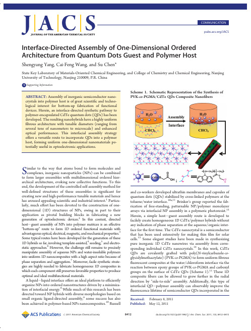
Published:May 12,2011COMMUNICATION /JACSInterface-Directed Assembly of One-Dimensional Ordered Architecture from Quantum Dots Guest and Polymer HostShengyang Yang,Cai-Feng Wang,and Su Chen*State Key Laboratory of Materials-Oriented Chemical Engineering,and College of Chemistry and Chemical Engineering,Nanjing University of Technology,Nanjing 210009,P.R.ChinabSupporting Information ABSTRACT:Assembly of inorganic semiconductor nano-crystals into polymer host is of great scienti fic and techno-logical interest for bottom-up fabrication of functional devices.Herein,an interface-directed synthetic pathway to polymer-encapsulated CdTe quantum dots (QDs)has been developed.The resulting nanohybrids have a highly uniform fibrous architecture with tunable diameters (ranging from several tens of nanometers to microscale)and enhanced optical performance.This interfacial assembly strategy o ffers a versatile route to incorporate QDs into a polymer host,forming uniform one-dimensional nanomaterials po-tentially useful in optoelectronic applications.Similar to the way that atoms bond to form molecules and complexes,inorganic nanoparticles (NPs)can be combined to form larger ensembles with multidimensional ordered hier-archical architecture,evoking new collective functions.To this end,the development of the controlled self-assembly method for well-de fined structures of these ensembles is signi ficant for creating new and high-performance tunable materials and hence has aroused appealing scienti fic and industrial interest.1Particu-larly,much e ffort has been devoted to the construction of one-dimensional (1D)structures of NPs,owing in part to their application as pivotal building blocks in fabricating a new generation of optoelectronic devices.2In this context,directed host Àguest assembly of NPs into polymer matrices is an e ffective “bottom-up ”route to form 1D ordered functional materials with advantageous optical,electrical,magnetic,and mechanical properties.3Some typical routes have been developed for the generation of these 1D hybrids so far,involving template-assisted,4seeding,5and electro-static approaches.6However,the challenge still remains to precisely manipulate assembly of aqueous NPs and water-insoluble polymers into uniform 1D nanocomposites with a high aspect ratio because of phase separation and aggregation.7Moreover,facile synthetic strate-gies are highly needed to fabricate homogeneous 1D composites in which each component still preserves favorable properties to produce optimal and ideal multifunctional materials.A liquid Àliquid interface o ffers an ideal platform to e fficiently organize NPs into ordered nanostructures driven by a minimiza-tion of interfacial energy.8While much of this research has been directed toward NP hybrids with diverse morphologies based on small organic ligand-directed assembly,9some success has also been achieved in polymer-based NPs nanocomposites.10Russelland co-workers developed ultrathin membranes and capsules of quantum dots (QDs)stabilized by cross-linked polymers at the toluene/water interface.10a,11Brinker ’s group reported the fab-rication of free-standing,patternable NP/polymer monolayer arrays via interfacial NP assembly in a polymeric photoresist.12Herein,a simple host Àguest assembly route is developed to facilely create homogeneous 1D CdTe/polymer hybrids without any indication of phase separation at the aqueous/organic inter-face for the first time.The CdTe nanocrystal is a semiconductor that has been used extensively for making thin film for solar cells.13Some elegant studies have been made in synthesizing pure inorganic 1D CdTe nanowires via assembly from corre-sponding individual CdTe nanocrystals.14In this work,CdTe QDs are covalently grafted with poly(N -vinylcarbazole-co -glycidylmethacrylate)(PVK-co -PGMA)to form uniform fibrous fluorescent composites at the water/chloroform interface via the reaction between epoxy groups of PVK-co -PGMA and carboxyl groups on the surface of CdTe QDs (Scheme 1).15These 1D composite fibers can be allowed to grow further in the radial direction by “side-to-side ”assembly.Additionally,this type of interfacial QD Àpolymer assembly can observably improve the fluorescence lifetime of semiconductor QDs incorporated in theScheme 1.Schematic Representation of the Synthesis of PVK-co -PGMA/CdTe QDs Composite Nano fibersReceived:February 8,2011polymeric matrix.It can be expected that this example of both linear axial organization and radial assembly methodology can be applied to fabricate spatial multiscale organic Àinorganic com-posites with desired properties of NPs and polymers.Figure 1a shows a typical scanning electron microscope (SEM)image of PVK-co -PGMA/CdTe QDs composite nano fi-bers obtained at the water/chloroform interface after dialysis.The as-prepared fibers have uniform diameters of about 250nm and typical lengths in the range of several tens to several hundreds of micrometers (Figures 1a and S4Supporting In-formation [SI]).Interestingly,PVK-co -PGMA/CdTe composite fibers can randomly assemble into nestlike ring-shaped patterns (Figures 1b and S5[SI]).Given the interaction among epoxy groups,the formation of nestlike microstructures could be attributed to incidental “head-to-tail ”assembly of composite fibers.Moreover,in order to establish the relationship between the role of epoxy groups and the formation of composite nano fibers,control experiments were performed,in which pure PGMA or PVK was used to couple CdTe QDs.The PGMA/CdTe composites could be obtained with fibrous patterns (Figure S6[SI]),but no fibrous composites were achieved at the biphase interface with the use of PVK under the same conditions.The microstructures and fluorescence properties of PVK-co -PGMA/CdTe composite fibers were further character-ized using laser confocal fluorescence microscopy (LCFM).Confocal fluorescence micrographs of composite fibers show that the di fferently sized QDs have no obvious in fluence on the morphology of composites (Figure 1c Àe).Clearly,uniform and strong fluorescence emission is seen throughout all the samples,and the size-dependent fluorescence trait of CdTe QDs in PVK-co -PGMA matrix remains well.In order to verify the existence and distribution of CdTe QDs in the fibers,transmission electron microscopy (TEM)was employed to examine the assembled structures.Figure 2a shows a TEM image of PVK-co -PGMA/CdTe QDs composite nano fi-bers,indicating each composite fiber shown in Figure 1a was assembled from tens of fine nano fibers.An individual fine nano fiber with the diameter of about 30nm is displayed in Figure 2b,from which we can see that CdTe QDs have been well anchored into the fiber with polymeric protection layer,revealing this graft-form process at the interface e ffectively avoidednon-uniform aggregation in view of well-dispersed CdTe QDs within the composite fiber,consistent with the LCFM observa-tion.Unlike previous works where the nanoparticles were ad-sorbed onto the polymer fibers,16CdTe QDs were expelled from the surface of fibers (∼2.5nm)in our system (Figure 2c),albeit the high percentage of QDs in the polymer host (23wt %)was achieved (Figure S7[SI]).This peculiarity undoubtedly confers CdTe QDs with improved stability.The clear di ffuse rings in the selected area electron di ffraction (SAED)pattern further indicate excellent monodispersion and finely preserved crystalline struc-ture of QDs in the nano fibers (Figure 2d).The SAED data correspond to the cubic zinc blende structure of CdTe QDs.A possible mechanism for the assembly of 1D nanostructure was proposed,as illustrated in Figure S8[SI].The hydrophilic epoxy groups of the PVK-co -PGMA chain in the oil phase orient toward the biphase interface and then react with carboxyl groups on the surface of CdTe QDs in the aqueous phase to a fford premier PVK-co -PGMA/CdTe QDs composites.Such nanocomposites will reverse repeatedly,resulting from iterative reaccumulation of epoxy groups at the interface and the reaction between the active pieces (i.e.,epoxy or carboxyl groups)in the composites with intact CdTe QDs or PVK-co -PGMA,forming well-de fined nano-fibers.The control experiments showing that the diameter of composite fibers increases with the increase in the concentration of PVK-co -PGMA are in agreement with the proposed mechan-ism (Figure S9[SI]).In addition,it is expected that the pure polymeric layer on the surface of the fibers (red rectangular zone in Figure 2c)will allow further assembly of fine fibers into thick fibers,and these fibers also could randomly evolve into rings,forming nestlike microstructures when the “head ”and “tail ”of fibers accidentally meet (Figure 1b).To further examine the assembly behavior of composite fibers,the sample of PVK-co -PGMA/CdTe QDs composite nano fibers were kept at the water/chloroform interface for an additional month in a close spawn bottle at room temperature (Figure S10[SI]).With longer time for assembly,thicker composite fibers with tens of micrometers in diameter were obtained (Figure 3a).These micro-fibers have a propensityto form twisted morphology (Figure 3a,b),Figure 1.(a,b)SEM images of PVK-co -PGMA/CdTe QDs composite nano fibers.(c Àe)Fluorescence confocal microscopy images of PVK-co -PGMA/CdTe QDs composite nano fibers in the presence of di fferently sized QDs:(c)2.5nm,(d)3.3nm,and (e)3.6nm.The excitation wavelengths are 488(c),514(d),and 543nm (e),respectively.Figure 2.(a,b)TEM images of PVK-co -PGMA/CdTe QDs composite nano fibers,revealing composite nano fiber assemblies.(c)HRTEM image and (d)SAED pattern of corresponding PVK-co -PGMA/CdTe QDs composite nano fibers.while their re fined nanostructures still reveal relatively parallel character and con firm the micro fibers are assembled from countless corresponding nano fibers (Figure 3c).The corresponding LCFM image of an individual micro fiber is shown in Figure 3d (λex =488nm),indicating strong and homogeneous green fluorescence.Another indication is the fluorescent performance of PVK-co -PGMA/CdTe QDs composite micro fibers (Figure 4a).The fluorescent spectrum of composite fibers takes on emission of both PVK-co -PGMA and CdTe QDs,which suggests that this interfacial assembly route is e ffective in integrating the properties of organic polymer and inorganic nanoparticles.It is worth noting that there is a blue-shift (from 550to 525nm)and broadening of the emission peak for CdTe QDs upon their incorporation into polymeric hosts,which might be ascribed to the smaller QD size and less homogeneous QD size distribution resulting from the photooxidation of QD surfaces.17Since the emission spectra of PVK-co -PGMA spectrally overlap with the CdTe QD absorption (Figure S11[SI]),energy transfer from the copolymer to the CdTe QDs should exist.18However,the photoluminescence of PVK-co -PGMA does not vanish greatly in the tested sample in comparison with that of polymer alone,revealing inferior energy transfer between the polymer host and the QDs.Although e fficient energy transfer could lead to hybrid materials that bring together the properties of all ingredients,18it is a great hurdle to combine and keep the intrinsic features of all constituents.19In addition,by changing the polymeric compo-nent and tailoring the element and size of QDs,it should be possible to expect the integration of organic and inorganic materials with optimum coupling in this route for optoelectronic applications.Finally,to assess the stability of CdTe QDs in the composite micro fibers,time-resolved photoluminescence was performed using time-correlated single-photon counting (TCSPC)parative TCSPC studies for hybrid PVK-co -PGMA/CdTe QDs fibers and isolated CdTe QDs in the solid state are presented in Figure 4b.We can see that the presence of PVK-co -PGMA remarkably prolongs the fluorescence lifetime (τ)of CdTe QDs.Decay traces for the samples were well fittedwith biexponential function Y (t )based on nonlinear least-squares,using the following expression.20Y ðt Þ¼R 1exp ðÀt =τ1ÞþR 2exp ðÀt =τ2Þð1Þwhere R 1,R 2are fractional contributions of time-resolved decaylifetimes τ1,τ2and the average lifetime τhcould be concluded from the eq 2:τ¼R 1τ21þR 2τ22R 1τ1þR 2τ2ð2ÞFor PVK-co -PGMA/CdTe QDs system,τh is 10.03ns,which is approximately 2.7times that of isolated CdTe QDs (3.73ns).Photooxidation of CdTe QDs during the assembly process can increase the surface states of QDs,causing a delayed emission upon the carrier recombination.21Also,the polymer host in this system could prevent the aggregation of QDs,avoid self-quench-ing,and delay the fluorescence decay process.22The increased fluorescence lifetime could be also ascribed to energy transfer from PVK-co -PGMA to CdTe QDs.18c The result suggests that this host Àguest assembly at the interface could find signi ficant use in the fabrication of QDs/polymer hybrid optoelectronic devices.In summary,we have described the first example of liquid/liquid interfacial assembly of 1D ordered architecture with the incorporation of the QDs guest into the polymer host.The resulting nanohybrids show a highly uniform fibrous architecture with tunable diameter ranging from nanoscale to microscale.The procedure not only realizes the coexistence of favorable properties of both components but also enables the fluorescence lifetime of QDs to be enhanced.This interesting development might find potential application for optoelectronic and sensor devices due to high uniformity of the 1D structure.Further e fforts paid on optimal regulation of QDs and polymer composition into 1D hybrid nanostructure could hold promise for the integration of desirable properties of organic and inorganic compositions for versatile dimension-dependent applications.In addition,this facile approach can be easily applied to various semiconductor QDs and even metal NPs to develop highly functional 1D nanocomposites.’ASSOCIATED CONTENTbSupporting Information.Experimental details,FT-IR,GPC,UV Àvis,PL,SEM,TGA analysis,and complete ref 9c.This material is available free ofcharge via the Internet at .Figure 3.(a,b)SEM and (c)FESEM images of PVK-co -PGMA/CdTe QDs composite micro fibers.(d)Fluorescence confocal microscopy images of PVK-co -PGMA/CdTe QDs composite micro fibers inthe presence of green-emitting QDs (2.5nm).Figure 4.(a)Fluorescence spectra of PVK-co -PGMA,CdTe QD aqueous solution,and PVK-co -PGMA/CdTe QDs composite micro-fibers.(b)Time-resolved fluorescence decay curves of CdTe QDs (2.5nm diameter)powders (black curve)and the corresponding PVK-co -PGMA/CdTe QDs composite micro fibers (green curve)mea-sured at an emission peak maxima of 550nm.The samples were excited at 410nm.Biexponential decay function was used for satisfactory fitting in two cases (χ2<1.1).’AUTHOR INFORMATIONCorresponding Authorchensu@’ACKNOWLEDGMENTThis work was supported by the National Natural Science Foundation of China(21076103and21006046),National Natural Science Foundation of China-NSAF(10976012),the Natural Science Foundations for Jiangsu Higher Education Institutions of China(07KJA53009,09KJB530005and10KJB5 30006),and the Priority Academic Program Development of Jiangsu Higher Education Institutions(PAPD).’REFERENCES(1)(a)Kashiwagi,T.;Du,F.;Douglas,J.F.;Winey,K.I.;Harris, R.H.;Shields,J.R.Nat.Mater.2005,4,928.(b)Shenhar,R.;Norsten, T.B.;Rotello,V.M.Adv.Mater.2005,17,657.(c)Akcora,P.;Liu,H.; Kumar,S.K.;Moll,J.;Li,Y.;Benicewicz,B.C.;Schadler,L.S.;Acehan, D.;Panagiotopoulos,A.Z.;Pryamitsyn,V.;Ganesan,V.;Ilavsky,J.; Thiyagarajan,P.;Colby,R.H.;Douglas,J.F.Nat.Mater.2009,8,354.(d)Dayal,S.;Kopidakis,N.;Olson,D.C.;Ginley,D.S.;Rumbles,G. J.Am.Chem.Soc.2009,131,17726.(e)Lin,Y.;B€o ker,A.;He,J.;Sill,K.; Xiang,H.;Abetz,C.;Li,X.;Wang,J.;Emrick,T.;Long,S.;Wang,Q.; Balazs,A.;Russell,T.P.Nature2005,434,55.(f)Park,S.;Lim,J.ÀH.; Chung,S.W.;Mirkin,C.A.Science2004,303,348.(g)Mai,Y.; Eisenberg,A.J.Am.Chem.Soc.2010,132,10078.(h)Mallavajula, R.K.;Archer,L.A.Angew.Chem.,Int.Ed.2011,50,578.(i)Kim,J.;Piao, Y.;Hyeon,T.Chem.Soc.Rev.2009,38,372.(2)(a)Xia,Y.;Yang,P.;Sun,Y.;Wu,Y.;Mayers,B.;Gates,B.;Yin, Y.;Kim,F.;Yan,H.Adv.Mater.2003,15,353.(b)Lu,X.;Wang,C.;Wei, Y.Small2009,5,2349.(c)Nie,Z.;Fava,D.;Kumacheva,E.;Zou,S.; Walker,G.C.;Rubinstein,M.Nat.Mater.2007,6,609.(3)(a)Huynh,W.U.;Dittmer,J.J.;Alivisatos,A.P.Science2002, 295,2425.(b)Balazs,A.C.;Emrick,T.;Russell,T.P.Science2006, 314,1107.(c)Ramanathan,T.;Abdala,A.A.;Stankovich,S.;Dikin, D.A.;Herrera-Alonso,M.;Piner,R.D.;Adamson,D.H.;Schniepp, H.C.;Chen,X.;Ruoff,R.S.;Nguyen,S.T.;Aksay,I.A.;Prud’homme, R.K.;Brinson,L.C.Nat.Nanotechnol.2008,3,327.(d)Tomczak,N.; Janczewski,D.;Han,M.;Vancso,G.J.Prog.Polym.Sci.2009,34,393.(e)Zhao,Y.;Thorkelsson,K.;Mastroianni,A.J.;Schilling,T.;Luther, J.M.;Rancatore,B.J.;Matsunaga,K.;Jinnai,H.;Wu,Y.;Poulsen,D.; Frechet,J.M.J.;Alivisatos,A.P.;Xu,T.Nat.Mater.2009,8,979.(f) Colfen,H.;Mann,S.Angew.Chem.,Int.Ed.2003,42,2350.(g)Sone,E.D.;Stupp,S.I.J.Am.Chem.Soc.2004,126,12756.(4)Chan,C.S.;De Stasio,G.;Welch,S.A.;Girasole,M.;Frazer,B.H.;Nesterova,M.V.;Fakra,S.;Banfield,J.F.Science2004,303,1656.(5)Tran,H.D.;Li,D.;Kaner,R.B.Adv.Mater.2009,21,1487.(6)Yuan,J.;M€u ller,A.H.E.Polymer2010,51,4015.(7)(a)Greenham,N.C.;Peng,X.;Alivisatos,A.P.Phys.Rev.B 1996,54,17628.(b)Lopes,W.A.;Jaeger,H.M.Nature2001,414,735.(c)Gupta,S.;Zhang,Q.;Emrick,T.;Balazs,A.Z.;Russell,T.P.Nat. Mater.2006,5,229.(8)(a)Wang,X.;Zhuang,J.;Peng,Q.;Li,Y.Nature2005,437,121.(b)Huang,J.;Kaner,R.B.J.Am.Chem.Soc.2004,126,851.(c)Binder, W.H.Angew.Chem.,Int.Ed.2005,44,5172.(d)Capito,R.M.;Azevedo, H.S.;Velichko,Y.S.;Mata,A.;Stupp,S.I.Science2008,319,1812.(e)Yin,Y.;Skaff,H.;Emrick,T.;Dinsmore,A.D.;Russell,T.P.Science 2003,299,226.(f)Arumugam,P.;Patra,D.;Samanta,B.;Agasti,S.S.; Subramani,C.;Rotello,V.M.J.Am.Chem.Soc.2008,130,10046.(g)Hou,L.;Wang,C.F.;Chen,L.;Chen,S.J.Mater.Chem.2010, 20,3863.(9)(a)Duan,H.;Wang,D.;Kurth,D.G.;Mohwald,H.Angew. Chem.,Int.Ed.2004,43,5639.(b)B€o ker,A.;He,J.;Emrick,T.;Russell,T.P.Soft Matter2007,3,1231.(c)Russell,J.T.;et al.Angew.Chem.,Int. Ed.2005,44,2420.(10)(a)Lin,Y.;Skaff,H.;B€o ker,A.;Dinsmore,A.D.;Emrick,T.; Russell,T.P.J.Am.Chem.Soc.2003,125,12690.(b)B€o ker,A.;Lin,Y.; Chiapperini,K.;Horowitz,R.;Thompson,M.;Carreon,V.;Xu,T.; Abetz,C.;Skaff,H.;Dinsmore,A.D.;Emrick,T.;Russell,T.P.Nat. Mater.2004,3,302.(11)Skaff,H.;Lin,Y.;Tangirala,R.;Breitenkamp,K.;B€o ker,A.; Russell,T.P.;Emrick,T.Adv.Mater.2005,17,2082.(12)Pang,J.;Xiong,S.;Jaeckel,F.;Sun,Z.;Dunphy,D.;Brinker,C.J.J.Am.Chem.Soc.2008,130,3284.(13)Fulop,G.;Doty,M.;Meyers,P.;Betz,J.;Liu,C.H.Appl.Phys. Lett.1982,40,327.(14)(a)Tang,Z.;Kotov,N.A.;Giersig,M.Science2002,297,237.(b)Zhang,H.;Wang,D.;Yang,B.;M€o hwald,H.J.Am.Chem.Soc.2006, 128,10171.(c)Yang,P.;Ando,M.;Murase,N.Adv.Mater.2009, 21,4016.(d)Srivastava,S.;Santos,A.;Critchley,K.;Kim,K.-S.; Podsiadlo,P.;Sun,K.;Lee,J.;Xu,C.;Lilly,G.D.;Glotzer,S.C.;Kotov, N.A.Science2010,327,1355.(15)Reis,A.V.;Fajardo,A.R.;Schuquel,I.T.A.;Guilherme,M.R.; Vidotti,G.J.;Rubira,A.F.;Muniz,.Chem.2009,74,3750.(16)(a)Djalali,R.;Chen,Y.;Matsui,H.J.Am.Chem.Soc.2002, 124,13660.(b)George,J.;Thomas,K.G.J.Am.Chem.Soc.2010, 132,2502.(17)(a)Yang,S.;Li,Q.;Chen,L.;Chen,S.J.Mater.Chem.2008, 18,5599.(b)Wang,Y.;Herron,N.J.Phys.Chem.1991,95,525.(c)Zhang,Y.;He,J.;Wang,P.N.;Chen,J.Y.;Lu,Z.J.;Lu,D.R.;Guo,J.; Wang,C.C.;Yang,W.L.J.Am.Chem.Soc.2006,128,13396.(d)Carrillo-Carri o n,C.;C a rdenas,S.;Simonet,B.M.;Valc a rcel,M. mun.2009,5214.(18)(a)Tessler,N.;Medvedev,V.;Kazes,M.;Kan,S.;Banin,U. Science2002,295,1506.(b)Zhang,Q.;Atay,T.;Tischler,J.R.;Bradley, M.S.;Bulovi c,V.;Nurmikko,A.V.Nat.Nanotechnol.2007,2,555.(c)Lutich,A.A.;Jiang,G.X.;Susha,A.S.;Rogach,A.L.;Stefani,F.D.; Feldmann,J.Nano Lett.2009,9,2636.(19)Li,M.;Zhang,J.;Zhang,H.;Liu,Y.;Wang,C.;Xu,X.;Tang,Y.; Yang,B.Adv.Funct.Mater.2007,17,3650.(20)Schr€o der,G.F.;Alexiev,U.;Grubm€u ller,H.Biophys.J.2005, 89,3757.(21)(a)Zhong,H.Z.;Zhou,Y.;Ye,M.F.;He,Y.J.;Ye,J.P.;He,C.; Yang,C.H.;Li,Y.F.Chem.Mater.2008,20,6434.(b)Sun,H.;Zhang, H.;Zhang,J.;Ning,Y.;Yao,T.;Bao,X.;Wang,C.;Li,M.;Yang,B. J.Phys.Chem.C2008,112,2317.(22)Kagan,C.R.;Murray,C.B.;Bawendi,M.G.Phys.Rev.B1996, 54,8633.。
各向异性生长诱导合成双室Janus介孔二氧化硅纳米颗粒赵东元

各向异性生长诱导合成双室Janus介孔二氧化硅纳米颗粒赵东元近年来,随着不同尺度和形貌的单一组分纳米材料合成技术的日益成熟,可控合成单分散的具有多种组分的纳米复合材料逐渐引起人们的关注。
多组分纳米复合材料最大的吸引力在于它能够实现单一组分所不能实现的功能和性质。
除了传统的对称复合方式,如核@壳(Core-Shell)、蛋黄@壳(Yolk-Shell)、合金等,非对称结构纳米复合材料具有形貌、组成、表面性质等不对称性的特点,在多重表面修饰、多客体分子输运等许多方面都具有潜在的应用价值。
目前,已有的合成不对称复合纳米材料的途径主要包括表面选择性修饰、界面组装、微流控等。
报道的非对称复合纳米材料主要集中在无机纳米晶、高分子、实心SiO2等。
而关于具有高比表面、非对称存储空间、表面性质、功能等非对称介孔材料的报道及合成手段非常有限,因此也限制了非对称纳米复合材料在客体分子(尤其是多客体分子)可控输运和释放方面的应用。
复旦大学的赵东元院士和张凡教授研究团队在前期提出的立方介孔孔道各向异性生长的基础上(J.Am.Chem.Soc.,2014,136,15086;J.Am.Chem.Soc.,2015,137,5903),在其最新研究成果中进一步拓展了二维六方介孔孔道的各向异性生长。
在该工作中,他们提出了一种“降解-重组”诱导介孔各向异性生长的方法,通过以SiO2纳米颗粒(或包覆SiO2的无机纳米晶核-壳结构)为种子、有机硅烷为前驱体、十六烷基三甲基溴化铵为结构导向剂,制备了均匀的一维不对称二元介孔硅纳米复合材料。
在该反应中,SiO2种子通过先部分降解、后重组的方法在硅基纳米颗粒种子上可控地生长一维的介孔硅纳米棒(二维六方孔道),结合以往发展的立方孔道介孔各向异性生长,可以进一步可控合成Cube&Sphere&Rod三元不对称结构。
在三元不对称结构中,每一个单元的组成、化学性质都可以通过改变骨架中的有机基团进行调控。
- 1、下载文档前请自行甄别文档内容的完整性,平台不提供额外的编辑、内容补充、找答案等附加服务。
- 2、"仅部分预览"的文档,不可在线预览部分如存在完整性等问题,可反馈申请退款(可完整预览的文档不适用该条件!)。
- 3、如文档侵犯您的权益,请联系客服反馈,我们会尽快为您处理(人工客服工作时间:9:00-18:30)。
Abstract
We study evolution of entanglement of two two-level atoms placed inside a multilayered microsphere. We show that due to inhomogeneity of the field modes this entanglement essentially depends on the atomic positions (asymmetrical entanglement) and also on the detuning between the atomic transitions and field frequencies. The robust and complete entanglement can be achieved even in the resonant case when the atoms have different effective coupling constants, and it can be extended in time if the detuning is large enough. We study analytically the lossless case and estimate numerically the effect of dissipative processes.
entanglement in various configurations has been discussed in [19], [20], [21]. Experimentally a robust entanglement was recently studied in[22] where an entanglement lasting for more than 20s was observed in a system of two trapped Ca+ ions. Authors [23] have shown that the degree of entanglement between the two atoms strongly depends on the mean photon number and the strength of two-photon correlations. In [24] a scheme for entangling N two-level atoms located close to the surface of a dielectric microsphere and atoms resonantly interacting with the field was considered. It was shown that in the particular case of two atoms located at diametrically opposite positions a perfect entanglement cannot be achieved even in the strong-coupling regime. In this paper we study two-atom entanglement interacting with field modes inside a microsphere covered with spherical dielectric alternating layers (coated microsphere). We are mainly interested: (i) in the frequency range of the high reflectivity field in λ/4 -stack; (ii) in the case when identical atoms are located asymmetrically inside the microsphere (i.e. the system is not symmetric with respect to a permutation of initially excited and non-excited atoms), so that the field inhomogeneity leads to different effective atom-field coupling constants ; and (iii) the atomic transitions can be both resonant and well detuned from the field peak frequency. The paper is organized as follows. In Section II we discuss basic equations for two atoms placed into a coated microsphere and the solution for this case. In Section III we present an analytical solution for probability amplitudes and apply it to studying the atomic concurrence. In Section IV we present a numerical study of the concurrence (tangle) dynamics. In the last Section, we discuss and summarize our conclusions.
arXiv:quant-ph/0603198v1 22 Mar 2006
2
Departamento de Fisica, Universidad de Guadalajara, Revolucion 1500, Guadalajara, Jalisco, 44420, Mexico. klimov@cencar.udg.mx
Asymmetrical two-atom entanglement in a coated microsphere
G.Burlak1 , A.Klimov2
1
Center for Research on Engineering and Applied Sciences, Autonomous State University of Morelos, Cuernavaca, Mor. 62210, Mexico. gburlTION
Recently, essential progress in fabrication and determination of optical properties of different kinds of microcavities with sizes about 0.1 − 20µm which contain semiconductor nanoclusters or quantum dots (QDs) has been achieved [see [1], [2] and references therein]. When semiconductor QDs are embedded in a spherical microcavity, the QD luminescence can be coupled with eigen modes of the electromagnetic field of the microcavity and a lower threshold of stimulated emission (or lasing modes) of QDs can be achieved. In recent papers [2],[3],[4] a coupling between the optical emission of embedded CdSex S1−x , QDs and spherical cavity modes was studied and a strong whispering gallery mode (WGM) resonance with high Q factors is registered in the photoluminescence spectra. Recently [5] quantum-confined semiconductor nanorods were used as highly polarized nanoemitters for active control of the polarization state of microcavity photons. Until now the modes with small numbers of spherical harmonics (SNM) are essentially less well-studied compared with whispering gallery modes (WGM) due to their rather low Q-factor caused by significant radiating losses. A possibility of strongly increasing the Qfactor of the microsphere was proposed in several papers, see e.g. [6], [7], [8]. The main idea consists in coating a microsphere by alternative layers of a spherical stack, which results in an increase of the Q factor up to values comparable for WGM, i.e. 107 − 109 . In a system with small mean photon number two spatially separated atoms in a cavity become entangled at some time moments as a result of sharing the re-radiated photons [9], [10], [11], [12], [13]. One of these schemes has been realized using Rydberg atoms coupled one by one to a high Q microwave superconducting microcavity [14]. In inhomogeneous structures, like multilayered microspheres, the quantized field properties are quite different from the unbounded case because of a non-uniformity of the cavity field, which becomes important for the entanglement dynamics. In spite of numerous experimental obstacles, mainly related with the decoherence problem, it seems very natural to entangle atoms placed in high-Q cavities (like microspheres) via interaction with modes of the cavity quantized field. A simple scheme for the generation of two-atom maximally entangled states via dispersive interaction was proposed in [15]. A number of papers report studies of the evolution of the entanglement in an atomic subsystem resonantly interacting with a single mode of the cavity field (two-atom Tavis-Cummings model) [16], [17], [18]. A robust generation of many-particle 2