LOGICAD 40_13_Application Structure (engl) v1.00
响应AutoCAD消息
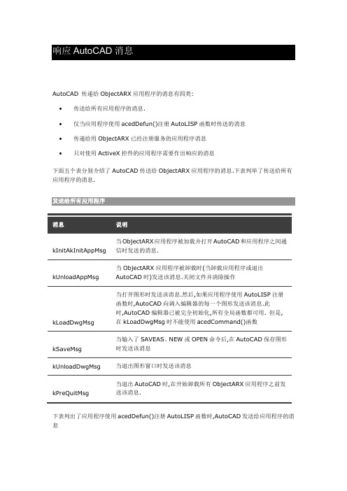
AutoCAD 传递给ObjectARX应用程序的消息有四类:•传送给所有应用程序的消息.•仅当应用程序使用acedDefun()注册AutoLISP函数时传送的消息•传递给用ObjectARX已经注册服务的应用程序消息•只对使用ActiveX控件的应用程序需要作出响应的消息下面五个表分别介绍了AutoCAD传送给ObjectARX应用程序的消息.下表列举了传送给所有应用程序的消息.kInitAkInitAppMsg 当ObjectARX应用程序被加载并打开AutoCAD和应用程序之间通信时发送的消息.kUnloadAppMsg 当ObjectARX应用程序被卸载时(当卸载应用程序或退出AutoCAD时)发送该消息.关闭文件并清除操作kLoadDwgMsg 当打开图形时发送该消息.然后,如果应用程序使用AutoLISP注册函数时,AutoCAD向调入编辑器的每一个图形发送该消息.此时,AutoCAD编辑器已被完全初始化,所有全局函数都可用. 但是,在kLoadDwgMsg时不能使用acedCommand()函数kSaveMsg 当输入了SAVEAS、NEW或OPEN命令后,在AutoCAD保存图形时发送该消息kUnloadDwgMsg 当退出图形窗口时发送该消息kPreQuitMsg 当退出AutoCAD时,在开始卸载所有ObjectARX应用程序之前发送该消息.下表列出了应用程序使用acedDefun()注册AutoLISP函数时,AutoCAD发送给应用程序的消息kInvkSubrMsg 当使用acedDefun()调用函数注册时发送此消息kEndMsg 只有当图形被修改,输入END命令后,需要保存时(当dbmode不为0)发送此消息.对NEW或OPEN命令,不发送此消息,而发送kSaveMsg和kLoadDwgMsg.对END命令,如果dbmode为0,则发送kQuitMsg,而不是kEndMsg.(2000后END命令停止使用)kQuitMsg 当输入QUIT命令后AutoCAD退出(退出但不存盘)时发送该消息. 注释: kQuitMsg消息发送与KPreQuitMsg消息之前.kCfgMsg 只有当改变了显示驱动程序,AutoCAD从配置程序返回时发送该消息. 下表列出了如果使用ObjectARX已注册一个服务时应用程序收到的消息.kDependencyMsg 当ObjectARX应用程序已经注册了一个AcRxService对象,并且该服务的从属计数器从0变为1时发送该消息kNoDependencyMsg 当ObjectARX应用程序已经注册了一个AcRxService对象,并且该服务的从属计数器从1变为0时发送该消息.下表列出了如果应用程序使用ActiveX Automation时需要响应的消息.kOleUnloadAppMsg 确定应用程序是否可以被卸载时发送该消息(没有其他应用程序引用ActiveX对象或界面).在rxdefs.h文件中,AppMsgCode类说明定义了这些枚举常量.我们必须确定ObjectARX应用程序将对哪一个消息作出响应.下表介绍了收到每一个消息后的推荐操作内容kInitAppMsg 允许注册服务、类、AcEd命令及反应器和AcRxDymicLinker 反应器;初始化应用程序系统资源,如设备和窗口;执行所用初始化工作;AcRx、AcEd和AcGe都被激活;如果想解锁和锁定其应用程序时,保存pkt参数值.不允许初始化设备驱动程序、激活任意接口资源,以特殊的顺序加载应用程序、调用AutoLISP或者打开任意数据库.否则会引起错误甚至导致系统崩溃.虽然有关的Ac结Rx和其他结构被激活,但AcDb和AcGi库通常尚未被激活 .kUnloadAppMsg 允许执行最后系统资源清理工作,任何在kInitAppMsg中开始或创建对象,应当在此处停止或析构.不要除在kIniAppMsg中激活库外,当调用了该消息时,AutoCAD 通常被卸载 .kOleUnloadAppMsg 允许只有使用ActiveX的应用程序响应此消息.不允许:如果应用程序可以被卸载(没有其他应用程序引用该应用程序的ActiveX对象或界面).以AcRx::kRetOK回应.如果应用程序不能被卸载,则以AcRx::kRetError回应kLoadDwgMsg 执行有关当前图编辑会话的初始化。
ioLogik E1200系列产品(E1210)更新说明书

Firmware for ioLogik E1200 Series (E1210) Release NotesSupported Operating SystemsNotesChangesApplicable ProductsBugs FixedN/A• Fixed inaccurate counter value when using Modbus to start a pulse (E1210/E1212/E1213).• Fixed opposite on/off pulse width display on web console (E1211/E1212/E1214).• Fixed that the offset scaling value will reset after changing the Alias name (E1260).• Fixed self-rebooting when entering URL in the browser for the configuration file.• Fixed EDS file import connection error.• Fixed failure when using save counter on power failure and reset counter at the same time (E1210/E1212/E1213).• Fixed inaccurate counter value when using high frequency (E1210/E1212/E1213).• Fixed that the trap community name is not included in the export file.• Fixed that EtherNet/IP cannot use the “Set Attribute Single” service.• Added an enable RESTful API setting in the configuration file.EnhancementsN/AioLogik E1210, ioLogik E1210-T• EtherNet/IP registration on Moxa’s licensing website is no longer required.• Added case insensitive content-length for RESTful API.New FeaturesN/AN/ASupported Operating SystemsNotesChangesApplicable ProductsBugs Fixed• Added SNMP Trap Community Setting to the web console.• Added a note on the password settings page that passwords are limited to 16 characters.• Fixed DHCP lease time did not ask for extension when half of the lease time elapsed.• Closed IP forwarding function (Port 0).• Closed UDP Port 161 when SNMP agent is disabled.• Fixed RESTful API header case-sensitive issue.• Fixed invalid token issue on login page when using Firefox.EnhancementsN/AioLogik E1210-T, ioLogik E1210• Added OPTIONS method for RESTful API.• Added quick access URI for RESTful API.New FeaturesN/A• This version of the firmware only works with ioSearch v2.0 or later versions.• To prevent system failure, only update the next or the previous released firmware version to prevent from system failure.Supported Operating SystemsNotesChangesApplicable ProductsBugs FixedN/A• Fixed file transfer problems when using the Chrome browser (e.g., firmware update, configuration import or export).EnhancementsN/AioLogik E1210, ioLogik E1210-T• Added the EtherNet/IP protocol.• Added RESTful API.• Added new registers for the Modbus/TCP protocol.• Added new OIDs for the SNMP protocol.• Modbus, EtherNet/IP, and RESTful services can be disabled (enabled by default).• Added sending heartbeat to port 9500 of MX-AOPC UA Server after the heartbeat function is enabled.• Increased password length from 8 to 16 characters.• Added a function to check special characters to prevent Cross-Site Scripting.• Passwords are now sent using the POST method instead of the GET method.New FeaturesN/AN/ASupported Operating SystemsNotesChangesApplicable ProductsBugs FixedN/AN/AEnhancementsN/AioLogik E1210, ioLogik E1210-T• Improved protocol efficiency for the ioLogik 2500 Series.New FeaturesN/AN/ASupported Operating SystemsNotesChangesApplicable ProductsBugs FixedN/A• Unable to disable the P2P heartbeat interval.• When the P2P client heartbeat is larger than 256 the time interval is incorrect.EnhancementsN/AioLogik E1210, ioLogik E1210-T• Supports ioLogik 2500 expansion mode.• Supports setting an initial value for a counter.New FeaturesN/AN/ASupported Operating SystemsNotesChangesApplicable ProductsBugs FixedN/A• The counter storage is deleted when the power fails.EnhancementsN/AioLogik E1210-T, ioLogik E1210• Supports SNMP protocol.• Added P2P heartbeat function.New FeaturesN/A• This version of firmware only works with ioSearch v1.5 or later versions.• Use the web console when upgrading the firmware from v1.0 to v1.10.Supported Operating SystemsNotesChangesApplicable ProductsBugs Fixed• Ensured that the system works properly after unstable power conditions.N/AEnhancementsN/AioLogik E1210, ioLogik E1210-TN/ANew FeaturesN/AN/ASupported Operating SystemsNotesChangesApplicable ProductsBugs Fixed• Improved firmware upgrading speed.• Removed Modbus/TCP ID checking mechanism.N/AEnhancementsN/AioLogik E1210, ioLogik E1210-T• Added "Locating I/O" function in General Settings.• Added Modbus address function code=0x08 for “ECHO” function.• Counter overflow status displayed in Channel Settings can be cleared manually.New FeaturesN/A• This version of the firmware only works with ioSearch v1.5 or later versions.• Use the web console when upgrading the firmware from v1.0 to v1.9.。
IKCS12F60F2A_C_Rev1_0_20100628(10)

F o r P o w e r M a n a g e m e n t A p p l i c a t i o nControl Integrated POwer System (CIPOS™)I K C S 12F 60F 2A I K C S 12F 60F 2CD a t a S he e t ,J un. 2010CIPOS™ IKCS12F60F2AIKCS12F60F2CRevision History: 2010-06Rev.1.0Authors: Junho Song*, Junbae Lee* and Daewoong Chung*, W. Frank**, W. Brunnbauer**LS Power Semitech*, Infineon Technologies**Edition 2010-01Published byLS Power Semitech Co., Ltd. Seoul, Korea© LS Power Semitech Co., Ltd.All Rights Reserved.Attention please!The information given in this data sheet shall in no event be regarded as a guarantee of conditions or characteristics. With respect to any examples or hints given herein, any typical values stated herein and/or any information regarding the application of the device, LS Power Semitech Co., Ltd. hereby disclaims any and all warranties and liabilities of any kind, including without limitation warranties of non-infringement of intellectual property rights of any third party.InformationFor further information on technology, delivery terms and conditions and prices please contact your nearest LS Power Semitech Co., Ltd. office or representatives ().WarningsDue to technical requirements components may contain dangerous substances. For information on the types in question please contact your nearest LS Power Semitech Co., Ltd. office or representatives.LS Power Semitech Co., Ltd. components may only be used in life-support devices or systems with the express written approval LS Power Semitech Co., Ltd., if a failure of such components can reasonably be expected to cause the failure of that life-support device or system, or to affect the safetyor effectiveness of that device or system. Life support devices or systems are intended to be implantedin the human body, or to support and/or maintain and sustain and/or protect human life. If they fail, it is reasonable to assume that the health of the user or other persons may be endangered.TRENCHSTOP® is a registered trademark of Infineon Technologies AG.CIPOS™ IKCS12F60F2AIKCS12F60F2CTable of contents:CIPOS™ Control Integrated POwer System (4)Features (4)Target Applications (4)Description (4)System Configuration (4)Certification (4)Internal Electrical Schematic (5)Pin Assignment (6)Pin Description (6)HIN1,2,3 and /LIN1,2,3 (Low side and high side control pins, Pin 15 - 20) (6)FLT-TEMP (temperature NTC, Pin 24) (7)ITRIP (Over-current detection function, Pin 21) (7)VDD, VSS (control side supply and reference, Pin 22, 23) (7)VB1,2,3 and VS1,2,3 (High side supplies, Pin 1, 2, 4, 5, 7, 8) (7)VRU, VRV, VRW (low side emitter, Pin 12, 13, 14) (7)V+ (positive bus input voltage, Pin 10) (7)Absolute Maximum Ratings (8)Module Section (8)IGBT and Diode Section (8)Control Section (9)Recommended Operation Conditions (9)Static Characteristics (10)Dynamic Characteristics (11)Integrated Components (12)Typical Application (12)Characteristics (13)Package Outline IKCS12F60F2A (17)Package Outline IKCS12F60F2C (18)CIPOS™ IKCS12F60F2AIKCS12F60F2CCIPOS™C ontrol I ntegrated PO wer S ystem Single In-Line Intelligent Power Module3Φ-bridge 600V / 12A @ 25°CFeatures•DCB isolated Single In-Line molded module •FAULT signal•TrenchStop® IGBTs with lowest V CE(sat)•Optimal adapted antiparallel diode for low EMI •Integrated bootstrap diode and capacitor •Rugged SOI gate driver technology with stability against transient and negative voltage •Fully compliant to 3.3V and 5V microcontrollers •Temperature sense•Under voltage lockout at all channels •Matched propagation delay for all channels •Low side emitter pins accessible for all phase current monitoring (open emitter)•Cross-conduction prevention•Lead-free terminal plating; RoHS compliant •Qualified according to JEDEC1 (high temperature stress tests for 1000h) for target applicationsTarget Applications•Washing machines•Consumer Fans and Consumer Compressors DescriptionThe CIPOS™ module family offers the chance for integrating various power and control components to increase reliability, optimize PCB size and system costs.This SIL-IPM is designed to control AC motors in variable speed drives for applications like air conditioning, compressors and washing machines. The package concept is specially adapted to power applications, which need extremely good thermal conduction and electrical isolation, but also EMI-save control and overload protection. The features of TrenchStop®IGBTs and antiparallel diodes are combined with a new optimized Infineon SOI gate driver for excellent electrical performance. The product provides a FAULT signal, which is significantly simplifying the system.System Configuration• 3 half-bridges with TrenchStop®IGBT & FW-diodes•3Φ SOI gate driver•Bootstrap diodes for high side supply •Integrated 100nF bootstrap capacitance •Temperature sensor, passive components for adaptions•Isolated heatsink•Creepage distance typ 3.2mmCertificationUL 1577 (UL file E314539)CIPOS™ IKCS12F60F2A IKCS12F60F2CInternal Electrical SchematicFigure 1: Internal SchematicVSS (23)/LIN3 (20)/LIN2 (19)/LIN1 (18)/HIN3 (17)/HIN2 (16)/HIN1 (15)VDD (22)VB1 (7)VB2 (4)VB3 (1)VRW (14)VRV (13)VRU (12)W, VS3 (2)V, VS2 (5)U, VS1 (8)V+ (10)/FLT-TEMP (24)ITRIP (21)CIPOS™ IKCS12F60F2A IKCS12F60F2CPin AssignmentPin Description/HIN1,2,3 and /LIN1,2,3 (Low side and high side control pins, Pin 15 - 20)These pins are active low and they are responsible for the control of the integrated IGBTsuch to guarantee LSTTL and CMOS compatibility down to 3.3V controller outputs. The maximum voltage at these pins is 5.5V and therefore fully compliant to 3.3V-microcontrollers. Pull-up resistor of about 75k Ω is internally provided to pre-bias inputs during supply start-up and a zener clamp is provided for pin protection purposes. Input schmitt-trigger and noise filter provide beneficial noise rejection to short input pulses. It is recommended for proper work of CIPOS™ not to provide an input pulse-width and PWM deadtimes lower than 1us.The integrated gate drive provides additionally a shoot through prevention capability which avoids the simultaneous on-state of two gate drivers ofFigure 2: Input pin structureCIPOS™ IKCS12F60F2A IKCS12F60F2Cthe same leg (i.e. HO1 and LO1, HO2 and LO2, HO3 and LO3).A minimum deadtime insertion of typ 380ns is also provided, in order to reduce cross-conduction of the external power switches./FLT-TEMP (temperature NTC, Pin 24)The TEMP terminal provides direct access to the NTC, which is referenced to VSS. An external pull-up resistor connected to +5V ensures, that the resulting voltage can be directly connected to the microcontroller.The same pin indicates a module failure in case of under voltage at pin VDD or in case of triggered over current detection at ITRIP. A pull-up resistor is externally required to bias the NTC. No temperature information is available during fault. ITRIP (Over-current detection function, Pin 21) CIPOS™ provides an over-current detection function by connecting the ITRIP input with the motor current feedback. The ITRIP comparator threshold (typ 0.46V) is referenced to VSS ground. A input noise filter (typ: t ITRIPMIN = 225ns) prevents the driver to detect false over-current events. Over-current detection generates a hard shut down of all outputs of the gate driver after the shutdown propagation delay of typically 900ns. The fault-clear time is set to typically to 4.7ms. VDD, VSS (control side supply and reference, Pin 22, 23)VDD is the low side supply and it provides power both to input logic and to low side output power stage. Input logic is referenced to VSS ground as well as the under-voltage detection circuit. The under-voltage circuit enables the device to operate at power on when a supply voltage of at least a typical voltage of V DDUV+ = 12.1V is at least present.The IC shuts down all the gate drivers power outputs, when the VDD supply voltage is below V DDUV- = 10.4V. This prevents the external power switches from critically low gate voltage levels during on-state and therefore from excessive power dissipation.VB1,2,3 and VS1,2,3 (High side supplies, Pin 1, 2, 4, 5, 7, 8)VB to VS is the high side supply voltage. The high side circuit can float with respect to VSS following the external high side power device emitter/source voltage.Due to the low power consumption, the floating driver stage is supplied by an integrated bootstrap circuit connected to VDD. This includes also integrated bootstrap capacitors of 100nF at each floating supply, which are located very close to the gate drive circuit.The under-voltage detection operates with a rising supply threshold of typical V BSUV+ = 12.1V and a falling threshold of V DDUV- = 10.4V according to Figure 4.VS1,2,3 provide a high robustness against negative voltage in respect of VSS of -50V. This ensures very stable designs even under rough conditions.Figure 4: Operation modesVRU, VRV, VRW (low side emitter, Pin 12, 13, 14)The low side emitters are available for current measurements of each phase leg. It is recommended to keep the connection to pin VSS as short as possible in order to avoid unnecessary inductive voltage drops.V+ (positive bus input voltage, Pin 10)The high side IGBT are connected to the bus voltage. It is recommended, that the bus voltage does not exceed 500V.CIPOS™ IKCS12F60F2AIKCS12F60F2CAbsolute Maximum Ratings(T J = 25°C, V DD = 15V Unless Otherwise Specified): Module SectionIGBT and Diode Section1 Monitored by pin 24CIPOS™ IKCS12F60F2A IKCS12F60F2CControl SectionRecommended Operation ConditionsAll voltages are absolute voltages referenced to V SS -Potential unless otherwise specified.IKCS12F60F2CStatic Characteristics(T c = 25°C, V DD = 15V, if not stated otherwise)1 Allowed number of short circuits: <1000; time between short circuits: >1s.Dynamic Characteristics(T c = 25°C, V DD = 15V, if not stated otherwise)Integrated ComponentsTypical Application1Characteristics(T c = 25°C, V DD = 15V, if not stated otherwise)I C , C O L L E C T O R C U R R E N TI F , f o r w a r d C U R R E N TV CE , COLLECTOR EMITTER VOLTAGEV F FORWARD VOLTAGEFigure 4. Typical IGBT output characteristicFigure 5. Typical diode forward current as afunction of forward voltaget , S W I T C H I N G T I M E S0A 5A 10A 15At , S W I T C H I N G T I M E S25℃50℃75℃100℃125℃I C , COLLECTOR CURRENTT vJ , JUNCTION TEMPERATUREFigure 6. Typical switching times as afunction of collector current (inductive load,T vJ =150°C,V CE =300VDynamic test circuit in Figure A)Figure 7. Typical switching times as afunction of junction temperature (inductive load, V CE = 300V, I C = 6A Dynamic test circuit in Figure A)E , S W I T C H I N G E N E R G YE , S W I T C H I N G E N E R G YI C , COLLECTOR CURRENTT vJ , JUNCTION TEMPERATUREFigure 8. Typical switching energy losses asa function of collector current (inductive load, T vJ =150°C, V CE =300VDynamic test circuit in Figure A)Figure 9. Typical switching energy losses asa function of junction temperature (inductive load, V CE = 300V, I C = 6A Dynamic test circuit in Figure A)R T S , N T C r e s i s t a n c eZ t h J C , T R A N S I E N T T H E R M A L R E S I S T A N C E10-210-1100 T NTC , NTC TEMPERATUREt P , PULSE WIDTHFigure 10. Characteristic of NTC as afunction of NTC temperatureFigure 11. Transient thermal impedance as afunction of pulse width (D =t P /T )Test Circuits and Parameter DefinitionFigure A: Dynamic test circuit Leakage inductance L σ =180nH Stray capacitance C σ =39pFFigure B: Definition of diodes switching characteristicsFigure C: Definition of Enable propagation delayFigure D: Switching times definition and switching energy definitionI RRMI FLIN1,2,3HIN1,2,3i CU , i CV , i v CEU , v CEV ∫⋅=Cx CEx dti v Eoff 0∫⋅=Eont Cx CEx dti v Eon 0Figure E: Short Pulse suppressionPackage Outline IKCS12F60F2ANote: There may occur discolorations on the copper surface without any effect of the thermal properties.Package Outline IKCS12F60F2CPackage Data。
斑马技术公司DS8108数字扫描仪产品参考指南说明书

3GPP TS 31.111 V8.4.0
3GPP TS 31.111 V8.4.0 (2009-01)Technical Specification3rd Generation Partnership Project;Technical Specification Group Core Network and Terminals;Universal Subscriber Identity Module (USIM)Application Toolkit (USAT)(Release 8)The present document has been developed within the 3rd Generation Partnership Project (3GPP TM ) and may be further elaborated for the purposes of 3GPP.The present document has not been subject to any approval process by the 3GPP Organisational Partners and shall not be implemented.This Specification is provided for future development work within 3GPP only. The Organisational Partners accept no liability for any use of this Specification.KeywordsUMTS, SIM, Card, LTE3GPPPostal address3GPP support office address650 Route des Lucioles - Sophia AntipolisValbonne - FRANCETel.: +33 4 92 94 42 00 Fax: +33 4 93 65 47 16InternetCopyright NotificationNo part may be reproduced except as authorized by written permission.The copyright and the foregoing restriction extend to reproduction in all media.© 2009, 3GPP Organizational Partners (ARIB, ATIS, CCSA, ETSI, TTA, TTC).All rights reserved.UMTS™ is a Trade Mark of ETSI registered for the benefit of its members3GPP™ is a Trade Mark of ETSI registered for the benefit of its Members and of the 3GPP Organizational PartnersLTE™ is a Trade Mark of ETSI currently being registered for the benefit of its Members and of the 3GPP Organizational PartnersContents Foreword (9)1Scope (10)2References (10)3Definitions, abbreviations and symbols (12)3.1Definitions (12)3.2Abbreviations (12)3.3Symbols (12)4Overview of USAT (12)4.1Profile Download (12)4.2Proactive UICC (13)4.3Data download to UICC (13)4.4Menu selection (13)4.5Call control by USIM (13)4.6MO Short Message control by USIM (13)4.7Event download (13)4.8Security (13)4.9Multiple card (13)4.10Timer Expiration (13)4.11Bearer Independent Protocol (13)4.12Description of the access technology indicator mechanism (14)4.13Description of the network search mode mechanism (14)4.14Geographical location discovery (14)5Profile download (14)5.1Procedure (14)5.2Structure and coding of TERMINAL PROFILE (14)5.3Definition of display parameters in Profile download (18)6Proactive UICC (18)6.1Introduction (18)6.2Identification of ME support (18)6.3General procedure (18)6.4Proactive UICC commands and procedures (18)6.4.1DISPLAY TEXT (18)6.4.2GET INKEY (18)6.4.3GET INPUT (19)6.4.4MORE TIME (19)6.4.5PLAY TONE (19)6.4.6POLL INTERVAL (19)6.4.7REFRESH (19)6.4.7.1EF IMSI changing procedure (19)6.4.7.2Generic Bootstrapping Procedure Request (19)6.4.8SET UP MENU (20)6.4.9SELECT ITEM (20)6.4.10SEND SHORT MESSAGE (20)6.4.11SEND SS (20)6.4.12SEND USSD (21)6.4.12.1MMI Mode (21)6.4.12.2Application Mode (22)6.4.13SET UP CALL (23)6.4.14POLLING OFF (23)6.4.15PROVIDE LOCAL INFORMATION (23)6.4.16SET UP EVENT LIST (25)6.4.17PERFORM CARD APDU (25)6.4.18POWER OFF CARD (25)6.4.23RUN AT COMMAND (25)6.4.24SEND DTMF (25)6.4.25LANGUAGE NOTIFICATION (25)6.4.26LAUNCH BROWSER (26)6.4.27OPEN CHANNEL (26)6.4.27.1OPEN CHANNEL related to CS bearer (26)6.4.27.2OPEN CHANNEL related to GPRS/3G packet service (26)6.4.27.3OPEN CHANNEL related to local bearer (26)6.4.27.4OPEN CHANNEL related to Default (network) Bearer (27)6.4.27.5OPEN CHANNEL related to I-WLAN bearer (27)6.4.27.6OPEN CHANNEL related to Terminal Server Mode (28)6.4.28CLOSE CHANNEL (28)6.4.29RECEIVE DATA (28)6.4.30SEND DATA (28)6.4.31GET CHANNEL STATUS (28)6.4.32SERVICE SEARCH (28)6.4.33GET SERVICE INFORMATION (28)6.4.34DECLARE SERVICE (28)6.4.35RETRIEVE MULTIMEDIA MESSAGE (28)6.4.36SUBMIT MULTIMEDIA MESSAGE (28)6.4.37DISPLAY MULTIMEDIA MESSAGE (28)6.4.38SET FRAMES (29)6.4.39GET FRAME STATUS (29)6.4.40Geographical Location Request (29)6.5Common elements in proactive UICC commands (30)6.6Structure of proactive UICC commands (30)6.6.1DISPLAY TEXT (30)6.6.2GET INKEY (30)6.6.3GET INPUT (30)6.6.4MORE TIME (30)6.6.5PLAY TONE (30)6.6.6POLL INTERVAL (30)6.6.7SET-UP MENU (30)6.6.8SELECT ITEM (30)6.6.9SEND SHORT MESSAGE (30)6.6.10SEND SS (31)6.6.11SEND USSD (31)6.6.12SET UP CALL (31)6.6.13REFRESH (31)6.6.14POLLING OFF (31)6.6.15PROVIDE LOCAL INFORMATION (32)6.6.16SET UP EVENT LIST (32)6.6.17PERFORM CARD APDU (32)6.6.18POWER OFF CARD (32)6.6.19POWER ON CARD (32)6.6.20GET READER STATUS (32)6.6.21TIMER MANAGEMENT (32)6.6.22SET UP IDLE MODE TEXT (32)6.6.23RUN AT COMMAND (32)6.6.24SEND DTMF COMMAND (32)6.6.25LANGUAGE NOTIFICATION (32)6.6.26LAUNCH BROWSER (32)6.6.27OPEN CHANNEL (33)6.6.27.1OPEN CHANNEL related to I-WLAN Bearer (33)6.6.28CLOSE CHANNEL (33)6.6.29RECEIVE DATA (33)6.6.30SEND DATA (33)6.6.31GET CHANNEL STATUS (33)6.6.36SUBMIT MULTIMEDIA MESSAGE (34)6.6.37DISPLAY MULTIMEDIA MESSAGE (34)6.6.38SET FRAMES (34)6.6.39GET FRAMES STATUS (34)6.6.40Geographical Location Request (34)6.7Command results (34)6.8Structure of TERMINAL RESPONSE (35)6.8.1Command details (36)6.8.2Device identities (36)6.8.3Result (36)6.8.4Duration (37)6.8.5Text string (37)6.8.6Item identifier (37)6.8.7Local information (37)6.8.8Call control requested action (37)6.8.9Result data object 2 (37)6.8.10Card reader status (37)6.8.11Card ATR (37)6.8.12R-APDU (37)6.8.13Timer identifier (37)6.8.14Timer value (37)6.8.15AT Response (38)6.8.16Text string 2 (38)6.8.17Channel data (38)6.8.18Channel status (38)6.8.19Channel data length (38)6.8.20Bearer description (38)6.8.21Buffer size (38)6.8.22Total Display Duration (38)6.8.23Service Availability (38)6.8.24Service Record (38)6.9Proactive UICC session and ME display interaction (38)6.10Handling of unknown, unforeseen and erroneous messages (38)6.11Proactive commands versus possible Terminal response (38)7ENVELOPE Commands (39)7.1Data download to UICC (39)7.1.1SMS-PP data download (39)7.1.1.1Procedure (39)7.1.1.2Structure of ENVELOPE (SMS-PP DOWNLOAD) (40)7.1.2Cell Broadcast data download (41)7.1.2.1Procedure (41)7.1.2.2Structure of ENVELOPE (CELL BROADCAST DOWNLOAD) (42)7.2Menu Selection (42)7.3Call Control and MO SMS control by USIM (42)7.3.1Call Control by USIM (42)7.3.1.1Procedure for mobile originated calls (42)7.3.1.2Procedure for Supplementary Services and USSD (43)7.3.1.3Indication to be given to the user (44)7.3.1.4Interaction with Fixed Dialling Number (45)7.3.1.5Support of Barred Dialling Number (BDN) service (45)7.3.1.6Structure of ENVELOPE (CALL CONTROL) (45)7.3.1.7Procedure for PDP Context Activation (47)7.3.2MO Short Message Control by USIM (48)7.3.2.1Description (48)7.3.2.2Structure of ENVELOPE (MO SHORT MESSAGE CONTROL) (48)7.3.2.3Indication to be given to the user (49)7.3.2.4Interaction with Fixed Dialling Number (49)7.4Timer Expiration (49)7.5.1.2Structure of ENVELOPE (EVENT DOWNLOAD – I-WLAN Access Status) (50)7.5.2Network Rejection event (51)7.5.2.1Procedure (51)7.5.2.2 Structure of ENVELOPE (EVENT DOWNLOAD – Network Rejection) (51)7.6USSD Data Download (52)7.6.1Procedure (52)7.6.2Structure of ENVELOPE (USSD Data Download) (52)7.7MMS Transfer Status (53)7.8MMS notification download (53)7.9Terminal Applications (53)7.10Geographical Location Reporting (53)7.10.1Procedure (53)7.10.2Structure of ENVELOPE (Geographical Location Reporting) (53)8COMPREHENSION-TLV data objects (54)8.1Address (54)8.2Alpha identifier (54)8.3Subaddress (54)8.4Capability configuration parameters (54)8.5Cell Broadcast Page (54)8.6Command details (54)8.7Device identities (55)8.8Duration (55)8.9Item (55)8.10Item identifier (55)8.11Response length (55)8.12Result (55)8.12.1Additional information for SEND SS (56)8.12.2Additional information for ME problem (56)8.12.3Additional information for network problem (56)8.12.4Additional information for SS problem (56)8.12.5Additional information for SMS problem (56)8.12.6Not used (57)8.12.7Additional information for USSD problem (57)8.12.8Additional information for interaction with call control or MO SM control (57)8.13SMS TPDU (57)8.14SS string (57)8.15Text string (58)8.16Tone (58)8.17USSD string (58)8.18File List (58)8.19Location Information (58)8.20IMEI (59)8.21Help Request (59)8.22Network Measurement Results (59)8.23Default Text (59)8.24Items Next Action Indicator (59)8.25Event list (59)8.26Cause (60)8.27Location status (60)8.28Transaction identifier (60)8.29BCCH channel list (60)8.30Call control requested action (61)8.31Icon Identifier (61)8.32Item Icon Identifier list (61)8.33Card reader status (61)8.34Card ATR (61)8.35C-APDU (61)8.36R-APDU (62)8.40AT Command (62)8.41AT Response (62)8.42BC Repeat indicator (62)8.43Immediate response (63)8.44DTMF string (63)8.45Language (63)8.46Timing Advance (63)8.47Browser Identity (63)8.48URL (63)8.49Bearer (63)8.50Provisioning File Reference (64)8.51Browser Termination Cause (64)8.52Bearer description (64)8.52.1Bearer parameters for CSD (64)8.52.2Bearer parameters for GPRS/3G Packet Service (64)8.52.3Bearer parameters for UTRAN Packet Service with extended parameters / HSDPA (65)8.52.4 Bearer parameters for I-WLAN (66)8.53Channel data (66)8.54Channel data length (66)8.55Buffer size (66)8.56Channel status (66)8.57Card reader identifier (66)8.58Other Address (66)8.59UICC/ME interface transport level (67)8.60AID (67)8.61Network Access Name (67)8.62Access Technology (67)8.63Display parameters (67)8.64Service Record (67)8.65Device Filter (67)8.66Service Search (67)8.67Attribute Information (67)8.68Service Availability (67)8.69Remote Entity Address (67)8.70Text Attribute (67)8.71Item Text Attribute List (68)8.72PDP context Activation parameters (68)8.73UTRAN Measurement Qualifier (68)8.74Multimedia Message Reference (68)8.75Multimedia Message Identifier (68)8.76Multimedia Message Transfer status (68)8.77MM Content Identifier (68)8.78Multimedia Message Notification (68)8.79Last Envelope (69)8.80Frames Layout (69)8.81Frames Information (69)8.82Frames identifier (69)8.83I-WLAN Identifier (69)8.84I-WLAN Access Status (69)8.85IMEISV (69)8.86Network search mode (69)8.87Battery State (69)8.88Browsing status (69)8.89Registry application data (70)8.90PLMNwAcT List (70)8.91Routing Area Identification (70)8.92Update/Attach Type (70)8.93Rejection Cause Code (71)8.96NMEA sentence (74)8.97PLMN List (74)9Tag values (74)9.1BER-TLV tags in ME to UICC direction (74)9.2BER-TLV tags in UICC TO ME direction (75)9.3COMPREHENSION-TLV tags in both directions (75)Type of Command and Next Action Indicator (75)I Allowed Type of command and Device identity combinations (75)11Security requirements (76)Annex A (normative): Support of USAT by Mobile Equipment (77)Annex B (informative): Example of DISPLAY TEXT Proactive UICC Command (78)Annex C (normative): Structure of USAT communications (79)Annex D (informative): ME display in proactive UICC session (80)Annex E (informative): Help information feature processing (81)Annex F (informative): Monitoring of events (82)Annex G (normative): Support of Multiple Card Operation (83)Annex H (informative): Multiple Card proactive command examples (84)Annex I (informative): Bearer independent protocol proactive command examples (85)Annex J (informative): WAP References (86)Annex K (informative): Use of USAT Bearer independent protocol for local links Bluetooth case (87)Annex L (informative): Bluetooth Service Discovery protocol (88)Annex M (informative): Use of USAT Bearer independent protocol for local links, server case (89)Annex N (informative): USSD information flow between the Network, the ME and the UICC (90)N.1MMI Mode (90)N.2Application Mode (92)N.3USSD Data Download (94)Annex O (informative): Geographical location information discovery information flow betweenthe ME and the UICC (94)Annex P (informative): Change History (96)ForewordThis Technical Specification (TS) has been produced by the 3rd Generation Partnership Project (3GPP).The contents of the present document are subject to continuing work within the TSG and may change following formal TSG approval. Should the TSG modify the contents of the present document, it will be re-released by the TSG with an identifying change of release date and an increase in version number as follows:Version x.y.zwhere:x the first digit:1 presented to TSG for information;2 presented to TSG for approval;3 or greater indicates TSG approved document under change control.y the second digit is incremented for all changes of substance, i.e. technical enhancements, corrections, updates, etc.z the third digit is incremented when editorial only changes have been incorporated in the document.1 ScopeThe present document defines the interface between the UICC and the Mobile Equipment (ME), and mandatory ME procedures, specifically for "USIM Application Toolkit".The present document refers in its majority to the ETSI TS 102 223 [32], which describes the generic aspects of application toolkits within the UICC.USAT is a set of commands and procedures for use during the network operation phase of 3G, in addition to those defined in TS 31.101 [13].Specifying the interface is to ensure interoperability between a UICC and an ME independently of the respective manufacturers and operators.The present document defines for 3G technology:- the commands;- the application protocol;- the mandatory requirements on the UICC and ME for each procedure.The present document does not specify any aspects related to the administrative management phase. Any internal technical realization of either the UICC or the ME are only specified where these reflect over the interface. The present document does not specify any of the security algorithms which may be used.Within the context of the present document, the term "terminal" used in ETSI TS 102 223 [32] refers to the Mobile Equipment (ME).Within the context of the present document, the term "NAA" used in ETSI TS 102 223 [32] refers to the USIM.2 ReferencesThe following documents contain provisions which, through reference in this text, constitute provisions of the present document.•References are either specific (identified by date of publication, edition number, version number, etc.) or non-specific.•For a specific reference, subsequent revisions do not apply.•For a non-specific reference, the latest version applies. In the case of a reference to a 3GPP document (includinga GSM document), a non-specific reference implicitly refers to the latest version of that document in the sameRelease as the present document.[1] 3GPP TS 22.002: "Circuit Bearer Services (BS) supported by a Public Land Mobile Network(PLMN)".[2] 3GPP TS 22.030: "Man-Machine Interface (MMI) of the User Equipment (UE)".[3] 3GPP TS 22.042: "Network Identity and Time Zone (NITZ); Service description; Stage 1".[4] 3GPP TS 23.038: "Alphabets and language-specific information".[5] 3GPP TS 23.040: "Technical realization of the Short Message Service (SMS)".[6] 3GPP TS 23.041: "Technical realization of Cell Broadcast Service (CBS)".[7] 3GPP TS 23.122: "Non-Access Stratum functions related to Mobile Station (MS) in idle mode".[8] 3GPP TS 24.007: "Mobile radio interface signalling layer 3; General aspects".[9] 3GPP TS 24.008: "Mobile radio interface layer 3 specification; Core network protocols; Stage 3".[10] 3GPP TS 24.011: "Point-to-Point (PP) Short Message Service (SMS) support on mobile radiointerface".[11] 3GPP TS 24.080: "Mobile radio layer 3 supplementary services specification; Formats andcoding".[12] 3GPP TS 27.007: "AT command set for 3G User Equipment (UE)".[13] 3GPP TS 31.101: "UICC-terminal interface; Physical and logical characteristics".[14] 3GPP TS 31.102: "Characteristics of the USIM application".[15] Void.[16] Void.[17] Void.[18] Void.[19] Void.[20] Void.[21] Void.[22] 3GPP TS 22.001: "Principles of circuit telecommunication services supported by a Public LandMobile Network (PLMN)".[23] 3GPP TS 23.048: "Security Mechanisms for the (U)SIM application toolkit; Stage 2".[24] Void.[25] Void.[26] Void.[27] 3GPP TS 44.018: "Mobile radio interface Layer 3 specification; Radio Resource ControlProtocol".[28] Void.[29] Void.[30] 3GPP TS 23.003: "Numbering, addressing and identification".[31] Void.[32] ETSI TS 102 223 Release 7: "Smart Cards; Card Application Toolkit".[33] 3GPP TR 21.905: "Vocabulary for 3GPP specifications".[34] 3GPP TS 22.101: "Service aspects; Service principles".[35] 3GPP TS 25.401: "UTRAN overall description".[36] 3GPP TS 25.413: "UTRAN Iu interface RANAP signalling".[37] 3GPP TS 24.090: "Unstructured Supplementary Service Data (USSD) - Stage 3".[38] 3GPP TS 25.331: "Radio Resource Control (RRC) Protocol Specification".[39] 3GPP TS 25.133: "Requirements for support of radio resource management".[40] Void.[41] 3GPP TS 31.115: "Secured packet structure for the (U)SIM Toolkit applications".[42] 3GPP TS 24.234: "3GPP System to WLAN Interworking; UE to Network protocols; Stage 3".[43] ETSI TS 101 220 Release 7: "Smart Cards; ETSI numbering system for telecommunicationapplication providers ".[44] 3GPP TS 23.032: "Universal Geographical Area Description (GAD)".[45] IEC 61162-1: "Maritime navigation and radio communication equipment and systems – Digitalinterfaces".3 Definitions, abbreviations and symbols3.1 DefinitionsFor the purposes of the present document, the terms and definitions given in ETSI TS 102 223 [32] and TR 21.905 [33] apply.3.2 AbbreviationsFor the purpose of the present document, the abbreviations given in ETSI TS 102 223 [32] and TR 21.905 [33] and the following apply:ADN Abbreviated Dialling NumberBroadcastCB CellCBMID Cell Broadcast Message IDentifierEGPRS EDGE General Packet Radio ServiceNumberFDN FixedDiallingGGSN Gateway GPRS Support NodeGPRS General Packet Radio ServiceGSM Global System for Mobile communicationsHSDPA High Speed Downlink Packet AccessMM MultimediaMessageServiceMMS MultimediaMessagingInterfaceMachineMMI ManPDP Packet Data Protocol, e.g., Ip or X25 or PPPRFU Reserved for Future UseServiceSS SupplementarySSC Supplementary Service Control stringUSAT USIM Application ToolkitUSIM Universal Subscriber Identity ModuleSupplementary Service DataUSSD UnstructuredWSID WLAN Specific IDentifier3.3 SymbolsFor the purposes of the present document, the following symbols apply:'0' to '9' and 'A' to 'F' The sixteen hexadecimal digits.4 Overview of USATThe USAT provides mechanisms which allow applications, existing in the UICC, to interact and operate with any ME which supports the specific mechanism(s) required by the application.The following mechanisms have been defined. These mechanisms are dependent upon the commands and protocols relevant to USAT in TS 31.101 [13].4.1 ProfileDownloadProfile downloading provides a mechanism for the ME to tell the UICC what it is capable of.4.2 ProactiveUICCProactive UICC gives a mechanism whereby the UICC can initiate actions to be taken by the ME. In addition to the actions listed in ETSI TS 102 223 [32], the USAT is extended with the following actions:- sending a SS control or USSD string.- requesting the ME to report current geographical location information.4.3 Data download to UICCData downloading to the UICC uses either dedicated commands (the transport mechanisms of SMS point-to-point and Cell Broadcast) or the Bearer independent protocol. Transferral of information over the UICC-ME interface uses the ENVELOPE command.4.4 MenuselectionSee ETSI TS 102 223 [32].4.5 Call control by USIMWhen this service is activated by the USIM, all dialled digit strings, supplementary service control strings and USSD strings or PDP context parameters are first passed to a USIM application before the ME sets up the call, the supplementary service operation or the USSD operation or establishes the PDP context. The ME shall also pass to the USIM application at the same time its current serving cell. The USIM application has the ability to allow, bar or modify the call, the supplementary service operation or, the USSD operation or PDP context activation by another context activation. The USIM application also has the ability to replace a call request, a supplementary service operation or a USSD operation by another call request or supplementary service operation or USSD operation.EXAMPLE: A call request can be replaced by a supplementary service operation or a USSD operation, and vice-versa.4.6 MO Short Message control by USIMWhen this service is activated by the USIM, all MO short messages are first passed to the USIM application before the ME sends the short message. The ME shall also pass to the USIM application at the same time its current serving cell. The USIM application shall have the ability to allow the sending, bar the sending or modify the destination address of the short message before sending it.download4.7 EventIn addition to the set of events defined in ETSI TS 102 223 [32], the following event may also be reported to the UICC: - Network Rejection4.8 SecuritySee ETSI TS 102 223 [32].card4.9 MultipleSee ETSI TS 102 223 [32].Expiration4.10 TimerSee ETSI TS 102 223 [32].4.11 Bearer Independent ProtocolSee ETSI TS 102 223 [32].4.12 Description of the access technology indicator mechanismSee ETSI TS 102 223 [32].4.13 Description of the network search mode mechanismSee ETSI TS 102 223 [32].4.14 Geographical location discoveryThe proactive command Geographical Location Request and the envelope command Geographical Location Reportingallows the UICC to request and receive the current geographical location information from the ME when the ME isequipped with a positioning feature and it is enabled (e.g. autonomous GPS, Assisted GPS or Assisted GNSS).download5 Profile5.1 ProcedureThe profile download instruction is sent by the ME to the UICC as part of the UICC initialization procedure. The UICCinitialization procedure is specified in TS 31.101 [13].If the UICC indicates the support of "Additional TERMINAL PROFILE after UICC activation" in its USIM ServiceTable, the ME shall handle the profile download procedure as specified in ETSI TS 102 223 [32].If the UICC does not indicate the support of "Additional TERMINAL PROFILE after UICC activation" in its USIMService Table, the profile download instruction shall only be sent by the ME to the UICC as part of the UICCinitialization procedure. However, if a USIM initialisation procedure is performed due to a refresh proactive command,the USIM initialisation procedure may also include a profile download.The profile(s) sent by the ME shall state the facilities relevant to USAT that are supported by the ME.5.2 Structure and coding of TERMINAL PROFILEDirection: ME to UICC.The command header is specified in TS 31.101 [13].Command parameters/data:LengthM/O/CDescription ClauseMlgth Profile -- Profile:Contents:- The list of USAT facilities that are supported by the ME.Coding:- 1 bit is used to code each facility:- bit = 1: facility supported by ME.- bit = 0: facility not supported by ME.NOTE: several bits may need to be set to 1 for the support of the same facility. This is because of backwardcompatibility with SAT: several options existed in SAT for a given facility, and they are mandatory inUSAT when this facility is supported.First byte (Download):b8 b7 b6 b5 b4 b3 b2b1[32]223TS102SeedownloadSMS-PPdatadownloaddataBroadcastCell[32]102223TSSeeBit = 1 if SMS-PP data download is supported223[32]TS102SeeBit = 1 if Call Control by USIM is supportedBit = 1 if Call Control by USIM is supportedSecond byte (Other):b8 b7 b6 b5 b4 b3 b2b1223[32]102TSSeeUSIMbyControlCallBit = 1 if Call Control by USIM is supportedbycontrolUSIMmessageMOshortBit = 1 if Call Control by USIM is supported223[32]TS102See[32]102223SeeTS223[32]TS102SeeThird byte (Proactive UICC):- See ETSI TS 102 223 [32].Fourth byte (Proactive UICC):b8 b7 b6 b5 b4 b3 b2b1223[32]102TSSeeSHORTSENDMESSAGEUICC:ProactiveSSSENDUICC:ProactiveUSSDSENDProactiveUICC:[32]223102SeeTS102[32]223TSSee[32]223102SeeTS(NMR)-inINFORMATIONPROVIDEProactiveUICC:LOCAL3GPP terms, this indicates support for GERANFifth byte (Event driven information):- See ETSI TS 102 223 [32].Sixth byte (Event driven information extensions):- See ETSI TS 102 223 [32].Seventh byte (Multiple card proactive commands) for class "a":- See ETSI TS 102 223 [32].Eighth byte (Proactive UICC):b8 b7 b6 b5 b4 b3 b2b1[32]223102SeeTS[32]223102SeeTS[32]223102SeeTS223[32]TS102See[32]223102SeeTS223[32]TS102See223[32]TS102SeeBit = 1 if Call Control by USIM is supportedNinth byte:b8 b7 b6 b5 b4 b3 b2b1223102[32]TSSee223[32]102TSSee[32]223See102TS223[32]102TSSeeINFORMATIONLOCAL(Timing ProactiveUICC:PROVIDEAdvance)[32]223TS102See223[32]TS102See223[32]TS102SeeTenth byte (Soft keys support) for class "d":- See ETSI TS 102 223 [32].Eleventh byte: (Soft keys information):- See ETSI TS 102 223 [32].Twelfth byte:- See ETSI TS 102 223 [32].Thirteenth byte:- See ETSI TS 102 223 [32].Fourteenth byte: (Screen height):- See ETSI TS 102 223 [32].Fifteenth byte: (Screen width):- See ETSI TS 102 223 [32].Sixteenth byte: (Screen effects):- See ETSI TS 102 223 [32].Seventeenth byte:b8 b7 b6 b5 b4 b3 b2b1223[32]TS102Seeissupported)"e"HSDPA(ifclassEighteenth byte:b8 b7 b6 b5 b4 b3 b2b1[32]223See102TSonGPRSCONTROLCALL[32]102223SeeTSNineteenth byte: (reserved for TIA/EIA-136 facilities):- See ETSI TS 102 223 [32].Twentieth byte: (reserved for TIA/EIA/IS-820 facilities):- See ETSI TS 102 223 [32].。
Studio 5000 Logix Designer 功能块图概念与操作说明书

Course NumberCCP152Course PurposeThis course is a skill-building programming course that provides you with an understanding of Studio 5000 Logix Designer® function block diagrams and terminology. This COURSE AGENDADAY 1• Creating a Function Block Diagram• Programming Logical Function Block Instructions • Programming Timer and Counter FunctionBlock Instructions• Programming Analog Function Block InstructionsControlLogix/Studio 5000 Studio 5000 Logix Designer Level 4:Function Block ProgrammingWHO SHOULD ATTENDIndividuals who are responsible for developing,debugging, and programming Logix5000 controllers using the Logix Designer application with function block diagrams should attend this course.Also, individuals who use ActiveX controls in an operator interface, such as FactoryTalk® View ME software, should attend this course.PREREQUISITESTo successfully complete this course, the following prerequisites are required:• Ability to perform basic Microsoft Windows tasks • Understanding of basic measurement and control theory, including basic loop control• Completion of the Studio 5000 Logix Designer Level 3: Project Development course (Course No. CCP143)or equivalent experience STUDENT MATERIALSTo enhance and facilitate the students’ learningexperiences, the following materials are provided as part of the course package:• Student Manual– Contains the topical outlines and exercises–Used to follow presentations, take notes, and work through exercises • Studio 5000 Logix Designer and Logix5000 Procedures Guide–Provides the steps required to complete basicsoftware tasks common to all Logix5000 controllersHANDS-ON PRACTICETo gain real-world programming experience, you will be given a functional specification for a fictitious batch process mixer, where bulk ingredients are mixed to produce a product. You will be the programmer for this batch mixer and must follow the functional specification, which will be the basis for all hands-on exercises in this course.After completing all exercises, you will have developed a Logix5000 project for the fictitious batch process mixer. As you develop your project, you will be given opportunities to run it using an ABT-TDCLX3-B workstation. This programming and process-based application experience can then be transferred to your own job responsibilities.NEXT LEARNING LEVELOnce you have mastered the function block diagram skills covered in this course, you will be able to expand your Logix5000 programming knowledge by attending other Logix5000 programming courses, such as the Studio 5000 Logix Designer Level 4: Kinetix 6000 (SERCOS) Programming course (Course No. CCN145).COURSE LENGTH This is a two-day course.Allen-Bradley, FactoryTalk, Logix5000 and Studio 5000 Logix Designer are trademarks of Rockwell Automation, Inc.Trademarks not belonging to Rockwell Automation are property of their respective companies. Publication GMST10-PP190I-EN-E – January 2020 | Supersedes Publication GMST10-PP190H-EN-E – April 2018Copyright © 2020 Rockwell Automation, Inc. All Rights Reserved. Printed in USA.To be respectful of the environment, Rockwell Automation is transitioning some of its training courses to a paperless format. Students are asked tocomplete downloads and bring personal devices to these classes. A full list of digital/paperless courses is currently available through your local distributor.。
javawasstartedbutreturnedexitcode=13简便解决办法
javawasstartedbutreturnedexitcode=13简便解决办法
始
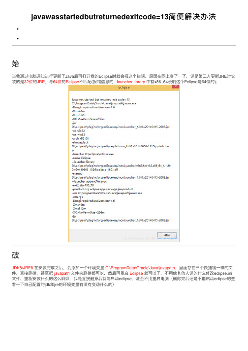
当我通过电脑通知进⾏更新了Java后再打开我的Eclipse时就会报这个错误,原因在⽹上查了⼀下,说是第三⽅更新JRE时安装的是32位的JRE,与64位的Eclipse不匹配(报错信息的– launcher.library 中有x86_64说明这个Eclipse是64位的);
破
JDK8/JRE8 在安装完成之后,会添加⼀个环境变量C:\ProgramData\Oracle\Java\javapath,⾥⾯存在三个快捷键⼀样的⽂件,直接删掉,甚⾄把javapath ⽂件夹删掉都可以,然后再重启Eclipse就可以了,不⽤像其他⼈说的什么修改eclipse.ini ⽂件、重新安装什么的这么⿇烦,我是直接删掉后就能启动eclipse,甚⾄不⽤重启电脑(删除完后还是不能启动eclipse的查看⼀下⾃⼰配置的jdk和jre的环境变量有没有变动什么的)。
AJA FS2 Installation and Operation Guide

AJA FS2 Installation and Operation Installation and Operation GuideB e c a u s e i t m a t t e r s .7/31/2012 Version: 1.1.0.0TrademarksAJA®, KONA®, Ki Pro®, KUMO®, and XENA® are registered trademarks of AJA Video, Inc. Io Express™,Io HD™ and Io™ are trademarks of AJA Video, Inc. Apple, the Apple logo, AppleShare, AppleTalk,FireWire, iPod, iPod Touch, Mac, and Macintosh are registered trademarks of Apple Computer, Inc.Final Cut Pro, QuickTime and the QuickTime Logo are trademarks of Apple Computer, Inc. All othertrademarks are the property of their respective holders.NoticeCopyright © 2012 AJA Video, Inc. All rights reserved. All information in this manual is subject tochange without notice. No part of the document may be reproduced or transmitted in any form,or by any means, electronic or mechanical, including photocopying or recording, without theexpress written permission of AJA Inc.FCC Emission InformationThis equipment has been tested and found to comply with the limits for a Class A digital device,pursuant to Part 15 of the FCC Rules. These limits are designed to provide reasonable protectionagainst harmful interference when the equipment is operated in a commercial environment. Thisequipment generates, uses and can radiate radio frequency energy and, if not installed and usedin accordance with the instruction manual, may cause harmful interference to radiocommunications. Operation of this equipment in a residential area is likely to cause harmfulinterference in which case the user will be required to correct the interference at his own expense.Changes or modifications not expressly approved by AJA Video can effect emission complianceand could void the user’s authority to operate this equipment.Contacting SupportTo contact AJA Video for sales or support, use any of the following methods:180 Litton Drive, Grass Valley, CA. 95945 USATelephone: +1.800.251.4224 or +1.530.274.2048Fax: +1.530.274.9442Web: SupportEmail:***************SalesEmail:*************1FS2 Installation and Operation Manual — Limited Warranty Limited WarrantyAJA Video warrants that this product will be free from defects in materials and workmanship for aperiod of five years from the date of purchase. If a product proves to be defective during thiswarranty period, AJA Video, at its option, will either repair the defective product without charge forparts and labor, or will provide a replacement in exchange for the defective product.In order to obtain service under this warranty, you the Customer, must notify AJA Video of the defectbefore the expiration of the warranty period and make suitable arrangements for the performanceof service. The Customer shall be responsible for packaging and shipping the defective product to adesignated service center nominated by AJA Video, with shipping charges prepaid. AJA Video shallpay for the return of the product to the Customer if the shipment is to a location within the countryin which the AJA Video service center is located. Customer shall be responsible for paying allshipping charges, insurance, duties, taxes, and any other charges for products returned to any otherlocations.This warranty shall not apply to any defect, failure or damage caused by improper use or improper orinadequate maintenance and care. AJA Video shall not be obligated to furnish service under thiswarranty a) to repair damage resulting from attempts by personnel other than AJA Videorepresentatives to install, repair or service the product, b) to repair damage resulting from improperuse or connection to incompatible equipment, c) to repair any damage or malfunction caused bythe use of non-AJA Video parts or supplies, or d) to service a product that has been modified orintegrated with other products when the effect of such a modification or integration increases thetime or difficulty of servicing the product.THIS WARRANTY IS GIVEN BY AJA VIDEO IN LIEU OF ANY OTHER WARRANTIES, EXPRESS OR IMPLIED.AJA VIDEO AND ITS VENDORS DISCLAIM ANY IMPLIED WARRANTIES OF MERCHANTABILITY ORFITNESS FOR A PARTICULAR PURPOSE. AJA VIDEO’S RESPONSIBILITY TO REPAIR OR REPLACEDEFECTIVE PRODUCTS IS THE WHOLE AND EXCLUSIVE REMEDY PROVIDED TO THE CUSTOMER FORANY INDIRECT, SPECIAL, INCIDENTAL OR CONSEQUENTIAL DAMAGES IRRESPECTIVE OF WHETHERAJA VIDEO OR THE VENDOR HAS ADVANCE NOTICE OF THE POSSIBILITY OF SUCH DAMAGES. Important Safety InformationHazard!This symbol, when used in the manual, indicates a serious health hazard with risk of injury ordeath.Warning!This symbol, when used in the manual, indicates a serious risk or threat to personal safety.Caution!This symbol, when used in the manual, indicates important safety and complianceinformation.Table of Contents ContentsAJA FS2 Installation and Operation Guide. . . . . . . . . . . . . . . . . . . . . . . . . . . . . . . . . .i Trademarks . . . . . . . . . . . . . . . . . . . . . . . . . . . . . . . . . . . . . . . . . . . . . . . . . . . . . . . . . . . . . . . . . . . . . . . . . . . . . . . ii Notice . . . . . . . . . . . . . . . . . . . . . . . . . . . . . . . . . . . . . . . . . . . . . . . . . . . . . . . . . . . . . . . . . . . . . . . . . . . . . . . . . . . . iiFCC Emission Information . . . . . . . . . . . . . . . . . . . . . . . . . . . . . . . . . . . . . . . . . . . . . . . . . . . . . . . . . . . . . . . . . ii Contacting Support . . . . . . . . . . . . . . . . . . . . . . . . . . . . . . . . . . . . . . . . . . . . . . . . . . . . . . . . . . . . . . . . . . . . . . . ii Limited Warranty. . . . . . . . . . . . . . . . . . . . . . . . . . . . . . . . . . . . . . . . . . . . . . . . . . . . . . . . . . . . . . . . . . . . . . . . . . iii Important Safety Information. . . . . . . . . . . . . . . . . . . . . . . . . . . . . . . . . . . . . . . . . . . . . . . . . . . . . . . . . . . . . . iii Contents. . . . . . . . . . . . . . . . . . . . . . . . . . . . . . . . . . . . . . . . . . . . . . . . . . . . . . . . . . . . . . . . . . . . . . . . . . . . . . . . . . vChapter 1:Introduction. . . . . . . . . . . . . . . . . . . . . . . . . . . . . . . . . . . . . . . . . . . . . . . . . . . . . . . . . . 1 Overview . . . . . . . . . . . . . . . . . . . . . . . . . . . . . . . . . . . . . . . . . . . . . . . . . . . . . . . . . . . . . . . . . . . . . . . . . . . . . . . . . 1 Video Features . . . . . . . . . . . . . . . . . . . . . . . . . . . . . . . . . . . . . . . . . . . . . . . . . . . . . . . . . . . . . . . . . . . . . . . . . 1 Available Video Formats. . . . . . . . . . . . . . . . . . . . . . . . . . . . . . . . . . . . . . . . . . . . . . . . . . . . . . . . . . . . . 2 Audio Features. . . . . . . . . . . . . . . . . . . . . . . . . . . . . . . . . . . . . . . . . . . . . . . . . . . . . . . . . . . . . . . . . . . . . . . . . 2Control and Other Features. . . . . . . . . . . . . . . . . . . . . . . . . . . . . . . . . . . . . . . . . . . . . . . . . . . . . . . . . . . . . 2Typical Applications. . . . . . . . . . . . . . . . . . . . . . . . . . . . . . . . . . . . . . . . . . . . . . . . . . . . . . . . . . . . . . . . . . . . 3FS2 Control . . . . . . . . . . . . . . . . . . . . . . . . . . . . . . . . . . . . . . . . . . . . . . . . . . . . . . . . . . . . . . . . . . . . . . . . . . . . . . . 4 Front Panel Control. . . . . . . . . . . . . . . . . . . . . . . . . . . . . . . . . . . . . . . . . . . . . . . . . . . . . . . . . . . . . . . . . . . . . 4Remote Web Browser Control. . . . . . . . . . . . . . . . . . . . . . . . . . . . . . . . . . . . . . . . . . . . . . . . . . . . . . . . . . . 4 SNMP Interface. . . . . . . . . . . . . . . . . . . . . . . . . . . . . . . . . . . . . . . . . . . . . . . . . . . . . . . . . . . . . . . . . . . . . . . . . . . . 4GPI Inputs and Outputs. . . . . . . . . . . . . . . . . . . . . . . . . . . . . . . . . . . . . . . . . . . . . . . . . . . . . . . . . . . . . . . . . . . . 5 Optional Remote Control Panel. . . . . . . . . . . . . . . . . . . . . . . . . . . . . . . . . . . . . . . . . . . . . . . . . . . . . . . . . . . . 5 Optional Fiber I/O. . . . . . . . . . . . . . . . . . . . . . . . . . . . . . . . . . . . . . . . . . . . . . . . . . . . . . . . . . . . . . . . . . . . . . . . . 5 Optional Dolby E Decoder and Encoder Cards. . . . . . . . . . . . . . . . . . . . . . . . . . . . . . . . . . . . . . . . . . . . . . 5 Technical Description . . . . . . . . . . . . . . . . . . . . . . . . . . . . . . . . . . . . . . . . . . . . . . . . . . . . . . . . . . . . . . . . . . . . . 6 Video Processors . . . . . . . . . . . . . . . . . . . . . . . . . . . . . . . . . . . . . . . . . . . . . . . . . . . . . . . . . . . . . . . . . . . . . . . 73G Support. . . . . . . . . . . . . . . . . . . . . . . . . . . . . . . . . . . . . . . . . . . . . . . . . . . . . . . . . . . . . . . . . . . . . . . . . . . . . 7Audio Processors. . . . . . . . . . . . . . . . . . . . . . . . . . . . . . . . . . . . . . . . . . . . . . . . . . . . . . . . . . . . . . . . . . . . . . . 8 What’s In The Box? . . . . . . . . . . . . . . . . . . . . . . . . . . . . . . . . . . . . . . . . . . . . . . . . . . . . . . . . . . . . . . . . . . . . . . . . 9In This Manual . . . . . . . . . . . . . . . . . . . . . . . . . . . . . . . . . . . . . . . . . . . . . . . . . . . . . . . . . . . . . . . . . . . . . . . . . . . 10Chapter 2:Controls, Indicators, and Connections . . . . . . . . . . . . . . . . . . . . . . . . . . . . . . . . . . .11 Control and Indicator Descriptions . . . . . . . . . . . . . . . . . . . . . . . . . . . . . . . . . . . . . . . . . . . . . . . . . . . . . . . 11 Front Panel Description . . . . . . . . . . . . . . . . . . . . . . . . . . . . . . . . . . . . . . . . . . . . . . . . . . . . . . . . . . . . . . . . . . 12 Alphanumeric Display. . . . . . . . . . . . . . . . . . . . . . . . . . . . . . . . . . . . . . . . . . . . . . . . . . . . . . . . . . . . . . . . . 12 Operational Summary. . . . . . . . . . . . . . . . . . . . . . . . . . . . . . . . . . . . . . . . . . . . . . . . . . . . . . . . . . . . . . 12 Pushbuttons. . . . . . . . . . . . . . . . . . . . . . . . . . . . . . . . . . . . . . . . . . . . . . . . . . . . . . . . . . . . . . . . . . . . . . . . . . 13 Control Knobs . . . . . . . . . . . . . . . . . . . . . . . . . . . . . . . . . . . . . . . . . . . . . . . . . . . . . . . . . . . . . . . . . . . . . . . . 15 LED Indicators . . . . . . . . . . . . . . . . . . . . . . . . . . . . . . . . . . . . . . . . . . . . . . . . . . . . . . . . . . . . . . . . . . . . . . . . 16 Incompatibility Alarms . . . . . . . . . . . . . . . . . . . . . . . . . . . . . . . . . . . . . . . . . . . . . . . . . . . . . . . . . . . . . . . . 17 Incompatible Video Formats. . . . . . . . . . . . . . . . . . . . . . . . . . . . . . . . . . . . . . . . . . . . . . . . . . . . . . . . 17 Example Reference and Video Incompatibility Alarms . . . . . . . . . . . . . . . . . . . . . . . . . . . . . . . 17 Rear Panel Description . . . . . . . . . . . . . . . . . . . . . . . . . . . . . . . . . . . . . . . . . . . . . . . . . . . . . . . . . . . . . . . . . . . 18 Connectors . . . . . . . . . . . . . . . . . . . . . . . . . . . . . . . . . . . . . . . . . . . . . . . . . . . . . . . . . . . . . . . . . . . . . . . . . . . 18 Connector Descriptions . . . . . . . . . . . . . . . . . . . . . . . . . . . . . . . . . . . . . . . . . . . . . . . . . . . . . . . . . . . . . . . . . . 19 AC Power Connectors . . . . . . . . . . . . . . . . . . . . . . . . . . . . . . . . . . . . . . . . . . . . . . . . . . . . . . . . . . . . . . 19 AES/EBU Digital Audio In and Out. . . . . . . . . . . . . . . . . . . . . . . . . . . . . . . . . . . . . . . . . . . . . . . . . . . 19 Balanced Analog Audio In and Out. . . . . . . . . . . . . . . . . . . . . . . . . . . . . . . . . . . . . . . . . . . . . . . . . . 19 RS-422 Port . . . . . . . . . . . . . . . . . . . . . . . . . . . . . . . . . . . . . . . . . . . . . . . . . . . . . . . . . . . . . . . . . . . . . . . . 19 GPI Inputs and Outputs. . . . . . . . . . . . . . . . . . . . . . . . . . . . . . . . . . . . . . . . . . . . . . . . . . . . . . . . . . . . . 19 LAN. . . . . . . . . . . . . . . . . . . . . . . . . . . . . . . . . . . . . . . . . . . . . . . . . . . . . . . . . . . . . . . . . . . . . . . . . . . . . . . . 19 SDI In and Out . . . . . . . . . . . . . . . . . . . . . . . . . . . . . . . . . . . . . . . . . . . . . . . . . . . . . . . . . . . . . . . . . . . . . 20 Optical Fiber In and Out . . . . . . . . . . . . . . . . . . . . . . . . . . . . . . . . . . . . . . . . . . . . . . . . . . . . . . . . . . . . 20 Component/Composite Analog Video In and Out . . . . . . . . . . . . . . . . . . . . . . . . . . . . . . . . . . . 20 HDMI In and Out . . . . . . . . . . . . . . . . . . . . . . . . . . . . . . . . . . . . . . . . . . . . . . . . . . . . . . . . . . . . . . . . . . . 20 Composite NTSC/PAL . . . . . . . . . . . . . . . . . . . . . . . . . . . . . . . . . . . . . . . . . . . . . . . . . . . . . . . . . . . . . . 20 Reference Video (looping) . . . . . . . . . . . . . . . . . . . . . . . . . . . . . . . . . . . . . . . . . . . . . . . . . . . . . . . . . . 20 About Inputs and Outputs. . . . . . . . . . . . . . . . . . . . . . . . . . . . . . . . . . . . . . . . . . . . . . . . . . . . . . . . . . . . . 21Chapter 3:Installation & Configuration . . . . . . . . . . . . . . . . . . . . . . . . . . . . . . . . . . . . . . . . . . . .23 Installation Overview. . . . . . . . . . . . . . . . . . . . . . . . . . . . . . . . . . . . . . . . . . . . . . . . . . . . . . . . . . . . . . . . . . . . . 23 Installation Summary. . . . . . . . . . . . . . . . . . . . . . . . . . . . . . . . . . . . . . . . . . . . . . . . . . . . . . . . . . . . . . . . . . 24 Unpacking. . . . . . . . . . . . . . . . . . . . . . . . . . . . . . . . . . . . . . . . . . . . . . . . . . . . . . . . . . . . . . . . . . . . . . . . . . . . . . . 25 Shipping Box Contents. . . . . . . . . . . . . . . . . . . . . . . . . . . . . . . . . . . . . . . . . . . . . . . . . . . . . . . . . . . . . . . . 25 Installing Optional Fiber Optic I/O Modules . . . . . . . . . . . . . . . . . . . . . . . . . . . . . . . . . . . . . . . . . . . . . . . 26 Installing Optional Cards . . . . . . . . . . . . . . . . . . . . . . . . . . . . . . . . . . . . . . . . . . . . . . . . . . . . . . . . . . . . . . . . . 26 Dolby Decoder Installation . . . . . . . . . . . . . . . . . . . . . . . . . . . . . . . . . . . . . . . . . . . . . . . . . . . . . . . . . 27 FS2 Chassis Installation. . . . . . . . . . . . . . . . . . . . . . . . . . . . . . . . . . . . . . . . . . . . . . . . . . . . . . . . . . . . . . . . . . . 27 Physical Requirements for Mounting the Chassis. . . . . . . . . . . . . . . . . . . . . . . . . . . . . . . . . . . . . . . 27 Chassis Dimensions . . . . . . . . . . . . . . . . . . . . . . . . . . . . . . . . . . . . . . . . . . . . . . . . . . . . . . . . . . . . . . . . 27 Cabling and Cooling Requirements . . . . . . . . . . . . . . . . . . . . . . . . . . . . . . . . . . . . . . . . . . . . . . . . . 27 Power Requirements. . . . . . . . . . . . . . . . . . . . . . . . . . . . . . . . . . . . . . . . . . . . . . . . . . . . . . . . . . . . . . . . . . 27 Network Connection. . . . . . . . . . . . . . . . . . . . . . . . . . . . . . . . . . . . . . . . . . . . . . . . . . . . . . . . . . . . . . . . . . . . . 291FS2 Installation and Operation Manual — ContentsNetwork Address . . . . . . . . . . . . . . . . . . . . . . . . . . . . . . . . . . . . . . . . . . . . . . . . . . . . . . . . . . . . . . . . . . . . . . . . 30Networking Using DHCP or Default Static IP . . . . . . . . . . . . . . . . . . . . . . . . . . . . . . . . . . . . . . . . . . . 30Networking the FS2 Using Your Own Static IP. . . . . . . . . . . . . . . . . . . . . . . . . . . . . . . . . . . . . . . . . . 30Using Ping to Test the Network Connection. . . . . . . . . . . . . . . . . . . . . . . . . . . . . . . . . . . . . . . . . . . . 32Mac Ping Procedure. . . . . . . . . . . . . . . . . . . . . . . . . . . . . . . . . . . . . . . . . . . . . . . . . . . . . . . . . . . . . . . . 32Windows PC Ping Procedure . . . . . . . . . . . . . . . . . . . . . . . . . . . . . . . . . . . . . . . . . . . . . . . . . . . . . . . 32Web Browser Control . . . . . . . . . . . . . . . . . . . . . . . . . . . . . . . . . . . . . . . . . . . . . . . . . . . . . . . . . . . . . . . . . . . . 32Software Update Installation . . . . . . . . . . . . . . . . . . . . . . . . . . . . . . . . . . . . . . . . . . . . . . . . . . . . . . . . . . . . . 33Download the Latest FS2 Software . . . . . . . . . . . . . . . . . . . . . . . . . . . . . . . . . . . . . . . . . . . . . . . . . . . . 33Unpack the Software. . . . . . . . . . . . . . . . . . . . . . . . . . . . . . . . . . . . . . . . . . . . . . . . . . . . . . . . . . . . . . . . . . 33Uploading and Installing the Software to the FS2 . . . . . . . . . . . . . . . . . . . . . . . . . . . . . . . . . . . . . . 33System Cabling. . . . . . . . . . . . . . . . . . . . . . . . . . . . . . . . . . . . . . . . . . . . . . . . . . . . . . . . . . . . . . . . . . . . . . . . . . 34System Video/Audio Cable Connections. . . . . . . . . . . . . . . . . . . . . . . . . . . . . . . . . . . . . . . . . . . . . . . 34GPI Connections . . . . . . . . . . . . . . . . . . . . . . . . . . . . . . . . . . . . . . . . . . . . . . . . . . . . . . . . . . . . . . . . . . . . . . 34FS2 Audio Level Choices—Pro or Consumer, US or EBU . . . . . . . . . . . . . . . . . . . . . . . . . . . . . . . . 35Chapter 4:Display Menus. . . . . . . . . . . . . . . . . . . . . . . . . . . . . . . . . . . . . . . . . . . . . . . . . . . . . . . .37Controlling the FS2 via Front Panel Display Menus. . . . . . . . . . . . . . . . . . . . . . . . . . . . . . . . . . . . . . . . 37Parameter Menus. . . . . . . . . . . . . . . . . . . . . . . . . . . . . . . . . . . . . . . . . . . . . . . . . . . . . . . . . . . . . . . . . . . . . 38Menu Group Buttons. . . . . . . . . . . . . . . . . . . . . . . . . . . . . . . . . . . . . . . . . . . . . . . . . . . . . . . . . . . . . . . . . . 39SELECT and ADJUST Knobs. . . . . . . . . . . . . . . . . . . . . . . . . . . . . . . . . . . . . . . . . . . . . . . . . . . . . . . . . . . . 39Menu Operation Examples. . . . . . . . . . . . . . . . . . . . . . . . . . . . . . . . . . . . . . . . . . . . . . . . . . . . . . . . . . . . . . . 40Status Pages. . . . . . . . . . . . . . . . . . . . . . . . . . . . . . . . . . . . . . . . . . . . . . . . . . . . . . . . . . . . . . . . . . . . . . . . . . 40Simple Menus: Config Format Alarm Filters . . . . . . . . . . . . . . . . . . . . . . . . . . . . . . . . . . . . . . . . . . . . 41Multiple Parameter Menus: Video 1 ProcAmp. . . . . . . . . . . . . . . . . . . . . . . . . . . . . . . . . . . . . . . . . . 42Multiple Field Parameters: IP Address. . . . . . . . . . . . . . . . . . . . . . . . . . . . . . . . . . . . . . . . . . . . . . . . . . 43STATUS Menu Group. . . . . . . . . . . . . . . . . . . . . . . . . . . . . . . . . . . . . . . . . . . . . . . . . . . . . . . . . . . . . . . . . . . . . 44S.1 I/O Status . . . . . . . . . . . . . . . . . . . . . . . . . . . . . . . . . . . . . . . . . . . . . . . . . . . . . . . . . . . . . . . . . . . . . . . . . 44S.2 Vid1 Format Status . . . . . . . . . . . . . . . . . . . . . . . . . . . . . . . . . . . . . . . . . . . . . . . . . . . . . . . . . . . . . . . . 44S.3 Vid1 Format Alarm Status. . . . . . . . . . . . . . . . . . . . . . . . . . . . . . . . . . . . . . . . . . . . . . . . . . . . . . . . . . 44S.4 Vid2 Format Status . . . . . . . . . . . . . . . . . . . . . . . . . . . . . . . . . . . . . . . . . . . . . . . . . . . . . . . . . . . . . . . . 45S.5 Vid 2 Format Alarm Status . . . . . . . . . . . . . . . . . . . . . . . . . . . . . . . . . . . . . . . . . . . . . . . . . . . . . . . . . 45S.6 Output Status . . . . . . . . . . . . . . . . . . . . . . . . . . . . . . . . . . . . . . . . . . . . . . . . . . . . . . . . . . . . . . . . . . . . . 45S.7 Power/Temp Alarm. . . . . . . . . . . . . . . . . . . . . . . . . . . . . . . . . . . . . . . . . . . . . . . . . . . . . . . . . . . . . . . . 45S.8 Caption Status. . . . . . . . . . . . . . . . . . . . . . . . . . . . . . . . . . . . . . . . . . . . . . . . . . . . . . . . . . . . . . . . . . . . . 46S.9 Dolby Status . . . . . . . . . . . . . . . . . . . . . . . . . . . . . . . . . . . . . . . . . . . . . . . . . . . . . . . . . . . . . . . . . . . . . . 46S.10 System Name . . . . . . . . . . . . . . . . . . . . . . . . . . . . . . . . . . . . . . . . . . . . . . . . . . . . . . . . . . . . . . . . . . . . 46REMOTE Menu Group. . . . . . . . . . . . . . . . . . . . . . . . . . . . . . . . . . . . . . . . . . . . . . . . . . . . . . . . . . . . . . . . . . . . 471 Remote Control. . . . . . . . . . . . . . . . . . . . . . . . . . . . . . . . . . . . . . . . . . . . . . . . . . . . . . . . . . . . . . . . . . . . . 471.1 Authentication . . . . . . . . . . . . . . . . . . . . . . . . . . . . . . . . . . . . . . . . . . . . . . . . . . . . . . . . . . . . . . . . . . . . 472.1–4 GPI IN 1–4 Response . . . . . . . . . . . . . . . . . . . . . . . . . . . . . . . . . . . . . . . . . . . . . . . . . . . . . . . . . . . . 483.1–4 GPI 1–4 OUT . . . . . . . . . . . . . . . . . . . . . . . . . . . . . . . . . . . . . . . . . . . . . . . . . . . . . . . . . . . . . . . . . . . . 49Interaction of Presets and GPIs . . . . . . . . . . . . . . . . . . . . . . . . . . . . . . . . . . . . . . . . . . . . . . . . . . . . . . . . 49Example of a Serial Recall. . . . . . . . . . . . . . . . . . . . . . . . . . . . . . . . . . . . . . . . . . . . . . . . . . . . . . . . . . . 49Example of an Unintended Recall. . . . . . . . . . . . . . . . . . . . . . . . . . . . . . . . . . . . . . . . . . . . . . . . . . . 49CONFIG Menu Group. . . . . . . . . . . . . . . . . . . . . . . . . . . . . . . . . . . . . . . . . . . . . . . . . . . . . . . . . . . . . . . . . . . . . 501 System Name . . . . . . . . . . . . . . . . . . . . . . . . . . . . . . . . . . . . . . . . . . . . . . . . . . . . . . . . . . . . . . . . . . . . . . . 502.1 IP Config . . . . . . . . . . . . . . . . . . . . . . . . . . . . . . . . . . . . . . . . . . . . . . . . . . . . . . . . . . . . . . . . . . . . . . . . . . 502.2 IP Address. . . . . . . . . . . . . . . . . . . . . . . . . . . . . . . . . . . . . . . . . . . . . . . . . . . . . . . . . . . . . . . . . . . . . . . . . 512.3 Subnet Mask . . . . . . . . . . . . . . . . . . . . . . . . . . . . . . . . . . . . . . . . . . . . . . . . . . . . . . . . . . . . . . . . . . . . . . 512.4 Default Gateway. . . . . . . . . . . . . . . . . . . . . . . . . . . . . . . . . . . . . . . . . . . . . . . . . . . . . . . . . . . . . . . . . . . 513 MAC Address (view only) . . . . . . . . . . . . . . . . . . . . . . . . . . . . . . . . . . . . . . . . . . . . . . . . . . . . . . . . . . . . 524.0 SNMP Enable . . . . . . . . . . . . . . . . . . . . . . . . . . . . . . . . . . . . . . . . . . . . . . . . . . . . . . . . . . . . . . . . . . . . . . 524.1 SNMP Trap Destination 1. . . . . . . . . . . . . . . . . . . . . . . . . . . . . . . . . . . . . . . . . . . . . . . . . . . . . . . . . . . 524.2 SNMP Trap Port 1. . . . . . . . . . . . . . . . . . . . . . . . . . . . . . . . . . . . . . . . . . . . . . . . . . . . . . . . . . . . . . . . . . 534.3 SNMP Trap Destination 2. . . . . . . . . . . . . . . . . . . . . . . . . . . . . . . . . . . . . . . . . . . . . . . . . . . . . . . . . . . 534.4 SNMP Trap Port 2. . . . . . . . . . . . . . . . . . . . . . . . . . . . . . . . . . . . . . . . . . . . . . . . . . . . . . . . . . . . . . . . . . 545 Power Supply Alarm. . . . . . . . . . . . . . . . . . . . . . . . . . . . . . . . . . . . . . . . . . . . . . . . . . . . . . . . . . . . . . . . . 546.1 Vid1 Format Alarm. . . . . . . . . . . . . . . . . . . . . . . . . . . . . . . . . . . . . . . . . . . . . . . . . . . . . . . . . . . . . . . . . 546.2 Vid2 Format Alarm. . . . . . . . . . . . . . . . . . . . . . . . . . . . . . . . . . . . . . . . . . . . . . . . . . . . . . . . . . . . . . . . . 557 Reference Alarm. . . . . . . . . . . . . . . . . . . . . . . . . . . . . . . . . . . . . . . . . . . . . . . . . . . . . . . . . . . . . . . . . . . . . 558 Hidden Menus . . . . . . . . . . . . . . . . . . . . . . . . . . . . . . . . . . . . . . . . . . . . . . . . . . . . . . . . . . . . . . . . . . . . . . 559 Display Intensity. . . . . . . . . . . . . . . . . . . . . . . . . . . . . . . . . . . . . . . . . . . . . . . . . . . . . . . . . . . . . . . . . . . . . 5510 Serial Number. . . . . . . . . . . . . . . . . . . . . . . . . . . . . . . . . . . . . . . . . . . . . . . . . . . . . . . . . . . . . . . . . . . . . . 5611 Software Version. . . . . . . . . . . . . . . . . . . . . . . . . . . . . . . . . . . . . . . . . . . . . . . . . . . . . . . . . . . . . . . . . . . 5612 Reboot . . . . . . . . . . . . . . . . . . . . . . . . . . . . . . . . . . . . . . . . . . . . . . . . . . . . . . . . . . . . . . . . . . . . . . . . . . . . 56 PRESET Menu Group . . . . . . . . . . . . . . . . . . . . . . . . . . . . . . . . . . . . . . . . . . . . . . . . . . . . . . . . . . . . . . . . . . . . . 571 Recall Preset . . . . . . . . . . . . . . . . . . . . . . . . . . . . . . . . . . . . . . . . . . . . . . . . . . . . . . . . . . . . . . . . . . . . . . . . 572 Store Preset . . . . . . . . . . . . . . . . . . . . . . . . . . . . . . . . . . . . . . . . . . . . . . . . . . . . . . . . . . . . . . . . . . . . . . . . . 57Interaction of Presets and GPIs. . . . . . . . . . . . . . . . . . . . . . . . . . . . . . . . . . . . . . . . . . . . . . . . . . . . . . . . . 57 SYSTEM Menu Group. . . . . . . . . . . . . . . . . . . . . . . . . . . . . . . . . . . . . . . . . . . . . . . . . . . . . . . . . . . . . . . . . . . . . 581 Component In Format. . . . . . . . . . . . . . . . . . . . . . . . . . . . . . . . . . . . . . . . . . . . . . . . . . . . . . . . . . . . . . . 582 Component Out Format . . . . . . . . . . . . . . . . . . . . . . . . . . . . . . . . . . . . . . . . . . . . . . . . . . . . . . . . . . . . . 583 Analog Audio Std . . . . . . . . . . . . . . . . . . . . . . . . . . . . . . . . . . . . . . . . . . . . . . . . . . . . . . . . . . . . . . . . . . . 584 SDI1 3G Detect. . . . . . . . . . . . . . . . . . . . . . . . . . . . . . . . . . . . . . . . . . . . . . . . . . . . . . . . . . . . . . . . . . . . . . 595 SDI2 Input Protect. . . . . . . . . . . . . . . . . . . . . . . . . . . . . . . . . . . . . . . . . . . . . . . . . . . . . . . . . . . . . . . . . . . 596 Fiber1 3G Detect . . . . . . . . . . . . . . . . . . . . . . . . . . . . . . . . . . . . . . . . . . . . . . . . . . . . . . . . . . . . . . . . . . . . 607 Fiber2 Input Protect . . . . . . . . . . . . . . . . . . . . . . . . . . . . . . . . . . . . . . . . . . . . . . . . . . . . . . . . . . . . . . . . . 618 Genlock Source . . . . . . . . . . . . . . . . . . . . . . . . . . . . . . . . . . . . . . . . . . . . . . . . . . . . . . . . . . . . . . . . . . . . . 619 Frame Rates. . . . . . . . . . . . . . . . . . . . . . . . . . . . . . . . . . . . . . . . . . . . . . . . . . . . . . . . . . . . . . . . . . . . . . . . . 6110 NTSC Standard. . . . . . . . . . . . . . . . . . . . . . . . . . . . . . . . . . . . . . . . . . . . . . . . . . . . . . . . . . . . . . . . . . . . . 6211 Composite Downconv. . . . . . . . . . . . . . . . . . . . . . . . . . . . . . . . . . . . . . . . . . . . . . . . . . . . . . . . . . . . . . 6212 HDMI RGB Range. . . . . . . . . . . . . . . . . . . . . . . . . . . . . . . . . . . . . . . . . . . . . . . . . . . . . . . . . . . . . . . . . . . 6214.0 AES/EBU SRC Mode. . . . . . . . . . . . . . . . . . . . . . . . . . . . . . . . . . . . . . . . . . . . . . . . . . . . . . . . . . . . . . . 6314.1–14.8 AES/EBU SRC. . . . . . . . . . . . . . . . . . . . . . . . . . . . . . . . . . . . . . . . . . . . . . . . . . . . . . . . . . . . . . . . 6315 Dolby Decoder Input. . . . . . . . . . . . . . . . . . . . . . . . . . . . . . . . . . . . . . . . . . . . . . . . . . . . . . . . . . . . . . . 6416 Dolby Decoder Mode. . . . . . . . . . . . . . . . . . . . . . . . . . . . . . . . . . . . . . . . . . . . . . . . . . . . . . . . . . . . . . . 6417 Dolby Decoder Aux Out . . . . . . . . . . . . . . . . . . . . . . . . . . . . . . . . . . . . . . . . . . . . . . . . . . . . . . . . . . . . 6518 Dolby Decoder Aux Mode . . . . . . . . . . . . . . . . . . . . . . . . . . . . . . . . . . . . . . . . . . . . . . . . . . . . . . . . . . 65。
- 1、下载文档前请自行甄别文档内容的完整性,平台不提供额外的编辑、内容补充、找答案等附加服务。
- 2、"仅部分预览"的文档,不可在线预览部分如存在完整性等问题,可反馈申请退款(可完整预览的文档不适用该条件!)。
- 3、如文档侵犯您的权益,请联系客服反馈,我们会尽快为您处理(人工客服工作时间:9:00-18:30)。
Date: November 2002
Slide number: 2
VANTAGE Training
Process Data & Interface Structures
A separate set of Process Data is used for each task :
In: Out: AuxOut: AuxIn:
For External input signals Output of main data or technological relevant external data Output of interim results, diagnostic or internally relevant data Input of configuration values and parameters
This task is used to control sequences within a package. (Cyclically- and Event Triggered)
This task is used for safety checks and initiating of safety actions caused by abnormal conditions. (Cyclically Triggered)
XxxTsk:
In this module the code for this tasks functioBiblioteka ality is situated.
XxxTskOut (Output Interface):
Write external data like signals to the field, or signals to other packages (Fast RDS, RFM, SHM, Messages). Do not pass values to another tasks in this package through the Output Interface module.
This task is used for fast control loops. (Cyclically Triggered)
This task is used for evaluation of the reference values within a package. (Cyclically Triggered)
VANTAGE Training
AppEv AppLp AppRef AppLgc AppSaf AppAnc
Standard Application Program & Task Structure
The task AppEvent is used to read configuration parameters for a package. The data are written independent of the communication mechanism like RDS or Config-Server. (Event Triggered)
The implementation of further substructures is recommended if the data overview will be improved, or the software implementation will be simplified.
Note: The configuration parameters for a task are accessed directly via the Process Data of the AppEv, e.g. PdEv.In.AuxRef.Xyz
Date: November 2002
Slide number: 1
VANTAGE Training
Program & Task Design of Application „XXX“
XxxTskIn
XxxTsk
XxxTskOut
XxxTskIn (Input Interface):
Read external data like signals from the field, or signals from other packages (Fast RDS, RFM, SHM, Messages). Do not pass values from another task in this package through the Input Interface module.
Remarks: In the uppermost level of the above mentioned modules (In, AppXxx and Out), direct access of Process Data Images of another task is allowed. Tsk specifies the function of the task within the application according to standard task structure
Date: November 2002
Slide number: 3
VANTAGE Training
XxxEvIn
x => PdEv.In.AuxRef.x y => PdEv.In.AuxSaf.y
This task is used to do low prior calculations and to write data which are required for the Engineer HMI. Depending on the communication mechanism the values are written to different variables (RDS or resource global variables). (Cyclically Triggered)