BOSCH焊接控制器简介
BOSCH焊接控制器简介ppt课件

Date: File:
2020/4/28 SSP1_01C.13
硬件介绍
Date: File:
2020/4/28 SSP1_01C.14
硬件介绍
Date: File:
2020/4/28 SSP1_01C.15
硬件介绍
Date: File:
2020/4/28 SSP1_01C.16
硬件介绍
Date: File:
Date: File:
2020/4/28 SSP1_01C.10
控制器电压指示灯:绿色表示焊接 控制器已经接了24V控制电压
控制器准备好信号灯:红的直流母 线电压大于60v时亮,有故障时灯 不亮。断电时要等灯全灭后,方 可进行维修操作
故障指示灯:没有任何故障时, 灯为绿色,表示已经准备好可以
焊接
焊接指示灯,当焊接进行时黄灯亮, 焊接完成黄灯灭
序列程序
1 2
Date: File:
2020/4/28 SSP1_01C.38
序列程序
3 焊接模式
3
Date: File:
2020/4/28 SSP1_01C.39
4 监控模式
序列程序
4
Date: File:
2020/4/28 SSP1_01C.40
序列程序
Date: File:
2020/4/28 SSP1_01C.41
一、BOSCH焊接控制器简介
Date: File:
2020/4/28 SSP1_01C.1
产品介绍 焊 接 控 制 器
Date: File:
2020/4/28 SSP1_01C.2
产品介绍
中频逆变器 PSI6300
中频逆变器6 - 36kA, 输入电 压400 - 480 V -20% (类型1)或者 500 - 690 V -10% (类型2), 5 0/60 Hz, 空冷( L ) 或者水冷( W ),联接PSG6000变压器,形成完整 的控制功能,额定电流110A (热连 续电流), I/O板的选择项:
BOSCH焊接控制器图纸
Alle Rechte bei Bosch Rexroth AG, auch für den Fall von Schutzrechtsanmeldungen. Jede Vefügungsbefugnis, wie Kopier- und Weitergaberecht, bei uns.
1
Table of contents
Alle Rechte bei Bosch Rexroth AG, auch für den Fall von Schutzrechtsanmeldungen. Jede Vefügungsbefugnis, wie Kopier- und Weitergaberecht, bei uns.
Harting 25-pole + PE
DP/TD
Ind.
Format
001 AB A3
This document, as well as the data, specifications and other information set forth in it, are the exclusive property of Bosch Rexroth AG. It may not be reproduced or given to third parties without its consent.
8
BOS_IND_1 BOS IND
a
b
c
d
e
WSC60HA-040.21-Basis en 1070091891
f
Sheet/Bl.
2
Sheets/Bl.
28
1
2
3
Welding transformer Gun 1
BOSCH焊接控制器6.03

1- 30
二、项目规划 1、新建项目 2、程序备份 3、程序恢复
1- 31
1、焊接控制器名:控制器名称不能重复,不能包含符号。最长48个字符。 2、焊接控制器注释:解释文本,不能包含符号。最长65个字符。 3、通道:通讯端口使用依赖硬件系统,可能的选项可从列表框中选择。 4、IP地址:控制器的以太网地址。
1- 25
计算机IP地址设定方法一。 注意:计算机IP地址要和焊接控制器IP地址设为同一组段既前三个地址要一 样。
1- 26
当设备硬件IP地址和计算机IP地址设置完成后可以连接设备设置设备的 软IP地址。在IE地址栏里输入硬件设置的IP地址然后回车即可出现如图画面 。在IP ADDRESS栏设置IP然后点击STORE CONFIGURATION软IP设置完成。最 后将硬件拨码开关全部拨到0,此时软IP地址生效。
1- 43
12、预压时间:当焊接信号发出后即进入预压时间。预压时间开始时控制器 启动比例阀控制焊枪闭合。当重复焊接时,预压只在第一点时激活。预压时 间的目的在于有充分的时间让焊钳闭合。 13、压合时间:电极压力在这个时间建立。在压合时间结束时焊枪必须完全 闭合。控制器会需要压力检测信号。 14、焊接1时间:预焊接时间,当不需要此过程时可以将该参数设置为0. 15、斜坡模式:有开关两种模式。当斜坡模式开时,可以自动为WELD2建立 斜坡上升和下降。具体参数由“斜坡上升时间”“斜坡上升电流”“斜坡下 降时间”“斜坡下降电流”来定义。
一、BOSCH焊接控制器简介 1、产品介绍 2、硬件介绍 1) 、外观展示 2)、指示灯含义 3)、工作原理 3、网络连接 1)、监控编程网络 2)、运行网络
1- 1
1- 2
力士乐PSI 6000-焊接控制器家族的各种功能可以方便的焊接难度很大 的高强度钢、吕合金、异种材料和多层板料等。 PSI 6000-是标准的1000赫兹中频/直流焊接技术。具有节能、高效、焊 接质量比传统的焊接方法有本质的提高。 -焊接质量的改善通过更高频率的电流调整来实现,产品质量大大超过 只能对供电频率调整的老式控制器。 -焊接更多材料的能力来源于更强的输出能量。 -飞溅的减少通过减少焊接时间和焊接电流来实现。 -电极寿命大大延长归功于在电极帽上更低热量和更小机械压力。 -更小更轻的中频变压器可以和焊钳整合在一起,大大减少工作强度、 加快上产节奏和提高能量效率,因此节能效果更明显。
Bosch Rexroth 焊机介绍

13
控制器的系统结构组成
Electric Drives and Controls © All rights reserved by Bosch Rexroth AG, even and especially in cases of proprietary rights applications. We also retain sole power of disposal, including all rights relating to copying, transmission and dissemination.
4
硬件熟悉
Electric Drives and Controls © All rights reserved by Bosch Rexroth AG, even and especially in cases of proprietary rights applications. We also retain sole power of disposal, including all rights relating to copying, transmission and dissemination.
K1 焊接电流接触器.
A1 Bosch Rexroth 焊接控制器 (timer) PSI6300.373L1.
Electric Drives and Controls © All rights reserved by Bosch Rexroth AG, even and especially in cases of proprietary rights applications. We also retain sole power of disposal, including all rights relating to copying, transmission and dissemination.
BOSCH焊接控制器603

Date: File:
2020/6/2 SSP1_01C.10
控制器电压指示灯:绿色表示焊接 控制器已经接了24V控制电压
控制器准备好信号灯:红的直流母 线电压大于60v时亮,有故障时灯 不亮。断电时要等灯全灭后,方 可进行维修操作
故障指示灯:没有任何故障时, 灯为绿色,表示已经准备好可以
焊接
焊接指示灯,当焊接进行时黄灯亮, 焊接完成黄灯灭
网络连接
Date: File:
2020/6/2 SSP1_01C.22
网络连接
Date: File:
2020/6/2 SSP1_01C.23
网络连接
Date: File:
2020/6/2 SSP1_01C.24
网络连接
Date: File:
2020/6/2 SSP1_01C.25
网络连接
Date: File:
2020/6/2 SSP1_01C.26
网络连接
Date: File:
2020/6/2 SSP1_.27
网络连接
Date: File:
2020/6/2 SSP1_01C.28
网络连接
Date: File:
2020/6/2 SSP1_01C.29
网络连接
2
1
Date: File:
2020/6/2 SSP1_01C.30
2020/6/2 SSP1_01C.42
T:交流控制器 I:中频控制器
Date: File:
2020/6/2 SSP1_01C.18
硬件介绍
Date: File:
2020/6/2 SSP1_01C.19
硬件介绍
Date: File:
BOSCH焊接控制器简介

中频逆变器 PSI6300
Date: File:
2018/10/26 SSP1_01C.3
产品介绍
Date: File:
2018/10/26 SSP1_01C.4
产品介绍
变压器
Date: File: 2018/10/26 SSP1_01C.5
硬件介绍
状态指示灯 1
2
Date: File:
2018/10/26 SSP1_01C.6
扩展序列程序
1 3
2
1
基本压力
2
新电极压力
3
变压力设置
Date: File:
2018/10/26 SSP1_01C.51
扩展序列程序
4
5
4
压力在压力步进1之后 压力在铣电极之后
5
Date: File:
2018/10/26 SSP1_01C.52
扩展序列程序
4 6 7 8
5
6
时间监控 参考时间 时间公差
电流校准程序
3 4 5
3
校准电流上限值 校准电流下限值 存储值
4 5
Date: File:
2018/10/26 SSP1_01C.80
电流校准程序
6 7
6
7
校准相关程序号 校准相关电极号
Date: File:
2018/10/26 SSP1_01C.81
电流校准程序
8 9 10
8
电流测量值1 电流测量值2 PU类型
2018/10/26 SSP1_01C.29
网络连接
2
1
Date: File:
2018/10/26 SSP1_01C.30
博世力士乐焊接产品介绍
同时,配套的新一代B S O O O 6 O 焊接控制软件结合强大的
SL Q 数据库 ,方便 的把 以上焊接数据进行统计和保存。
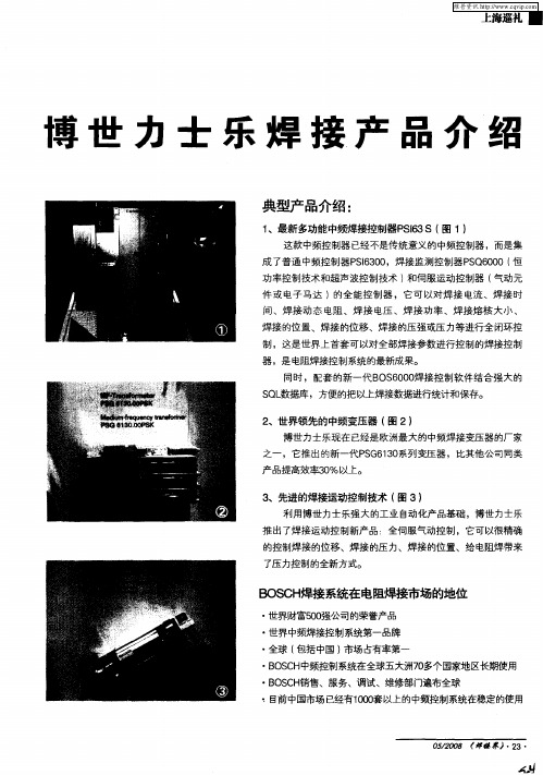
2 、世界领先的中频变压器 ( 2) 图
博世 力士乐现在 已经 是欧洲最 大的中频焊 接变压 器的厂家
之一 ,它推 出的新一代 P G6 0 S 1 系列 变压 器 ,比其 他公司 同类 3
・
完整 的故障代码系统 ,只要查手册就 可以维修和维护
・ ・
完整的联 网解决 方案
・
不仅可 以简单联网 ,还可 以在全球任何地 方都 管理 它
・ ・
C E安全产品质量体 系认 证
・
・
焊 接质 量比交流 的大大提高 ,并且属于节能降耗新一
・
铁道部青 岛四方车辆厂
代产品
・
南京华飞显示器公司 上海威 图电子机械公司
B CH OS 焊接系统在 电阻焊接市场的地位
・
世界财富5 0 0 强公司 的荣誉 产品
・
世界中频焊接控制系统第一品牌
・
全球 ( 包括中国 ) 市场占有率第一
BSH O C  ̄频控制 系统在全球五大洲 7 多个 国家地 区长期使用 0
・
・
Байду номын сангаас
BSH O C 销售、服务、调试、维修部门遍布全球
・
・
沈 阳宝 马汽车 北京奔驰汽车
一
・
无故障时间大大增加
・
焊接控制器 内部没有需要连 接的东西 ,只 要会 编程就
・
汽奥迪汽车
可 以 了
・ ・
海南马 自达汽车 上海汇众汽车 东风汽车有 限公司 长安汽车有 限公司 扬卅『 亚星奔驰客车
博世交流焊接控制器说明书

PST 6000PST 6000.XXX Thyristor Power Unit with integrated control functionTechnical Information101EditionPST 6000PST 6000.XXX Thyristor Power Unitwith integrated control functionTechnical Information1070 080 058-101 (2001.04) GBReg. no. 16149-03E2000-2001This manual is the exclusive property of Robert Bosch GmbH,also in the case of Intellectual Property Right applications.Without their consent it may not be reproduced or given to third parties.Discretionary charge 10.-1070 080 058-101 (2001.04) GB ContentsPage 1Safety instructions 1-1. . . . . . . . . . . . . . . . . . . . . . . . . . . . 1.1Safety instructions and symbols attached to the product 1-1. . . . . . 1.2Safety instructions and symbols used in this manual 1-2. . . . . . . . . 1.3Intended use 1-3. . . . . . . . . . . . . . . . . . . . . . . . . . . . . . . . . . . . . . . . . . . 1.4No admittance for persons fitted with cardiac pacemakers 1-4. . . . 1.5Qualified personnel 1-5. . . . . . . . . . . . . . . . . . . . . . . . . . . . . . . . . . . . . . 1.6Installation and assembly 1-6. . . . . . . . . . . . . . . . . . . . . . . . . . . . . . . . 1.7Electrical connection 1-9. . . . . . . . . . . . . . . . . . . . . . . . . . . . . . . . . . . . . 1.8Ensuring EMC of the completely assembled system 1-12. . . . . . . . . 1.9Operation of the thyristor power units 1-13. . . . . . . . . . . . . . . . . . . . . . 1.10Retrofits and modifications by the user 1-14. . . . . . . . . . . . . . . . . . . . . 1.11Maintenance, repair 1-15. . . . . . . . . . . . . . . . . . . . . . . . . . . . . . . . . . . . . 1.12Working safely 1-16. . . . . . . . . . . . . . . . . . . . . . . . . . . . . . . . . . . . . . . . . . 2Setup 2-1. . . . . . . . . . . . . . . . . . . . . . . . . . . . . . . . . . . . . . . . 2.1Features 2-1. . . . . . . . . . . . . . . . . . . . . . . . . . . . . . . . . . . . . . . . . . . . . . . 2.2Modules and components 2-2. . . . . . . . . . . . . . . . . . . . . . . . . . . . . . . . 2.3Function 2-4. . . . . . . . . . . . . . . . . . . . . . . . . . . . . . . . . . . . . . . . . . . . . . . 2.4Monitoring 2-4. . . . . . . . . . . . . . . . . . . . . . . . . . . . . . . . . . . . . . . . . . . . . . 3Notes on Rating 3-1. . . . . . . . . . . . . . . . . . . . . . . . . . . . . . 4Commissioning 4-1. . . . . . . . . . . . . . . . . . . . . . . . . . . . . . . 5Maintenance 5-1. . . . . . . . . . . . . . . . . . . . . . . . . . . . . . . . . . 6Malfunction 6-1. . . . . . . . . . . . . . . . . . . . . . . . . . . . . . . . . . 7Type overview 7-1. . . . . . . . . . . . . . . . . . . . . . . . . . . . . . . . 7.1Features 7-1. . . . . . . . . . . . . . . . . . . . . . . . . . . . . . . . . . . . . . . . . . . . . . . 8PST 6100.XXX L 8-1. . . . . . . . . . . . . . . . . . . . . . . . . . . . . . 8.1PST 6100.XXX L overview 8-1. . . . . . . . . . . . . . . . . . . . . . . . . . . . . . . 8.2Explanation of drawings 8-1. . . . . . . . . . . . . . . . . . . . . . . . . . . . . . . . . . 8.3PST 6100.XXX L front panel 8-2. . . . . . . . . . . . . . . . . . . . . . . . . . . . . . 8.4Technical data, PST 6100.XXX L 8-4. . . . . . . . . . . . . . . . . . . . . . . . . . 8.5Dimensioned drawing, PST 6100.XXX L 8-5. . . . . . . . . . . . . . . . . . . 8.6Electrical connection, PST 6100.XXX L 8-6. . . . . . . . . . . . . . . . . . . . 8.7Load diagram, PST 6100.XXX L 8-7. . . . . . . . . . . . . . . . . . . . . . . . . . 8.8Accessories, PST 6100.XXX L 8-8. . . . . . . . . . . . . . . . . . . . . . . . . . . . 8.8.1Dimensioned drawing, accessories kit 8-8. . . . . . . . . . . . . . . . . . . . . 8.9Ordering accessories 8-10. . . . . . . . . . . . . . . . . . . . . . . . . . . . . . . . . . . .1070 080 058-101 (2001.04) GBPage9PST 6250.XXX L 9-1. . . . . . . . . . . . . . . . . . . . . . . . . . . . . . 9.1PST 6250.XXX L overview 9-1. . . . . . . . . . . . . . . . . . . . . . . . . . . . . . . 9.2Explanation of drawings 9-1. . . . . . . . . . . . . . . . . . . . . . . . . . . . . . . . . . 9.3PST 6250.XXX L front panel 9-2. . . . . . . . . . . . . . . . . . . . . . . . . . . . . . 9.4Technical data, PST 6250.XXX L 9-4. . . . . . . . . . . . . . . . . . . . . . . . . . 9.5Dimensioned drawing, PST 6250.XXX L 9-5. . . . . . . . . . . . . . . . . . . 9.6Electrical connection, PST 6250.XXX L 9-6. . . . . . . . . . . . . . . . . . . . 9.7Load diagram, PST 6250.XXX L 9-7. . . . . . . . . . . . . . . . . . . . . . . . . . 9.8Accessories, PST 6250.XXX L 9-8. . . . . . . . . . . . . . . . . . . . . . . . . . . . 9.8.1Dimensioned drawing, accessories kit 9-8. . . . . . . . . . . . . . . . . . . . . 9.9Ordering accessories 9-10. . . . . . . . . . . . . . . . . . . . . . . . . . . . . . . . . . . . 10CE declaration of conformity 10-1. . . . . . . . . . . . . . . . . . A Annex A-1. . . . . . . . . . . . . . . . . . . . . . . . . . . . . . . . . . . . . . . . A.1Index A-1. . . . . . . . . . . . . . . . . . . . . . . . . . . . . . . . . . . . . . . . . . . . . . . . . .1070 080 058-101 (2001.04) GB1Safety instructionsThe products described were developed, manufactured and tested in com-pliance with the fundamental safety requirements of the EU machine direc-tive. These products normally pose no danger to persons or property if used in accordance with the handling stipulations and safety notes prescribed for their configuration, mounting, and proper operation.Nevertheless, there is some residual risk!Therefore, you should read this manual before installing, connecting or com-missioning the products. Store this manual in a place to which all users have access at any time!This manual describes the:D PST 6000 thyristor power unitsThe functions of the integrated weld timer are described in a separate manual.1.1Safety instructions and symbols attached to the productWarning of dangerous electrical voltage!Lug for connecting PE conductor only!1070 080 058-101 (2001.04) GB1.2Safety instructions and symbols used in this manualDANGEROUS ELECTRICAL VOLTAGE This symbol is used to warn of dangerous electrical voltage. Failure to observe the instructions in this manual in whole or in part may result in per-sonal injury.DANGER This symbol is used wherever insufficient or lacking compliance with in-structions may result in personal injury .CAUTION This symbol is used wherever insufficient or lacking compliance with in-structions may result in damage to equipment or data files ..Note: This symbol is used to draw the user’s attention to special cir-cumstances.L This symbol is used if user activities are required.Modifications in this manual as compared to a previous edition are marked by black vertical bars in the margin.1070 080 058-101 (2001.04) GB1.3Intended usePST 6000 thyristor power units are designed for connection of welding trans-formers.These thyristor power units are designed for use in D resistance welding of metals andD are suitable for operation in industrial environments as per DIN EN 50082-2 and 50081-2 on electromagnetic compatibility (EMC).They are not intended for any other use!DANGER Any use other than for the purpose indicated may result in personal injury of the user or third parties or in damage to equipment, the workpiece to be welded, or environmental damage.Therefore, our products must never be used for any other than their respective intended purpose!.Note: For operation in residential environments, in trade and commer-cial applications and small enterprises, an individual permit of the na-tional authority or test institution is required; in Germany, please contact the Regulierungsbehörde für Telekommunikation und Post (RegTP) or its local branch offices.The faultless, safe functioning of the product requires proper transport, stor-age, erection and installation as well as careful operation.1070 080 058-101 (2001.04) GB1.4No admittance for persons fitted with cardiac pacemakersDANGERWARNING for persons fitted with cardiac pacemakers!T o protect persons fitted with cardiac pacemakers, noĆentry signsshould be posted because pacemaker malfunction (missedpulses,total failure), pacemaker program interference or even programdestruction is to be expected.Note: We recommend that warning sings like the one shown below are posted at every entrance to manufacturing shops housing resistance-welding equipment:No entry for persons with cardiac pacemakers!Danger!DIN 400231070 080 058-101 (2001.04) GB 1.5Qualified personnelThe requirements as to qualified personnel are based on the requirements profiles as defined by the ZVEI (Zentralverband Elektrotechnik und Elek-tronikindustrie - German Electrical and Electronic Manufacturers’ Associ-ation) and the VDMA (Verband deutscher Maschinen- und Anlagenbau -German Engineering Federation) in:Weiterbildung in der Automatisierungstechnik edited by: ZVEI and VDMA Maschinenbau Verlag Postfach 71 08 64D-60498 Frankfurt .This manual is designed for technicians and engineers with special welding training and skills. They must have a sound knowledge of the hardware com-ponents of the weld control system, the PST 6000 thyristor power units and the welding transformers.Interventions in the hardware and software of our products, unless de-scribed otherwise in this manual, are reserved to specialized Bosch person-nel.Tampering with the hardware or software, ignoring warning signs attached to the components, or non-compliance with the warning notes given in this manual can result in serious bodily injury or property damage.Only skilled persons as defined in IEV 826-09-01 who are familiar with the contents of this manual may install and service the products described.Such personnel areD those who, being well trained and experienced in their field and familiar with the relevant standards, are able to analyze the work to be carried out and recognize any hazards.D those who have acquired the same amount of expert knowledge through years of experience that would normally be acquired through formal tech-nical training.DANGER!An exception are persons with cardiac pacemakers! The strong magnetic fields occurring in resistance welding may af-fect the proper functioning of pacemakers. This may be fatal or cause serious personal injury!Therefore, persons with pacemakers must stay clear of resistance welding systems.We recommend that warning sings as per DIN 40023 are posted at ev-ery entrance to manufacturing shops housing resistance-welding equipment.Please note our comprehensive range of training courses. More information is available from our training center (Phone: +49 / 6062 / 78-258).1.6Installation and assemblyDANGERNon-workmanlike installation or mounting may lead to personal in-jury or damage to property.Therefore, it is essential that you take the technical data (environ-mental conditions) into account for installation or mounting.Installation or mounting must be carried out by skilled personnelonly.DANGERInsufficient degree of protection may be life-threatening or causedamage to property!The degree of protection of thyristor power units is IP 20. They mustbe installed in switchgear cubicles providing a degree of protectionof no less than IP 54.DANGERDanger of injury and of damage to property through incorrect instal-lation!Devices and, in particular, operating means, must be installed so asto be properly safeguarded against unintentional operation or con-tact.DANGERRisk of injury from sharp-edged sheet metal!Wear protective gloves!DANGERDanger of personal injury and damage to property through inade-quate fastening!The place for installing the thyristor power units, and their methodof fastening, must be suitable for their weight!Injuries and bruises may be caused by lifting weights which are tooheavy or by sharp metal edges!Due to the heavy weight of individual modules several persons arerequired for installation and assembly.Wear safety shoes and safety gloves!DANGEROUS ELECTRICAL VOLTAGEBefore the modules are installed, the respective mounting station must be safely isolated from supply and properly safeguarded to pre-vent unintentional or unauthorized reclosing.CAUTIONShort circuits!When cut-outs are drilled or sawed in switchgear cubicles, metal burr may get into modules already installed there. Or, when cooling water lines are connected, water may leak into the thyristor power units installed.The possibility of short circuits occurring in the process or even the destruction of the devices cannot be entirely ruled out. Therefore, guard any existing modules well before you install a new module! Any and all warranty excluded in case of non-compliance.CAUTIONHeat accumulation!Thyristor power units must be mounted with a minimum clearance of 100 mm on top and at the bottom. Without this minimum clearance, heat may accumulate and cause power unit failure.CAUTIONIn the case of airĆcooled thyristor power units, the temperature inside the housing must stay within the specified range. Thyristor power units must always be operated under forcedĆair cooling conditions. Convection cooling will not be sufficient!CAUTIONLeaks in the cooling water circuit may cause consequential damage! Cooling water leaks may damage adjacent components. Therefore, when mounting water-cooled modules, always ensure that other de-vices in the switchgear cabinet are well protected against leaking cooling water.CAUTIONDamage to property through inappropriate or insufficient cooling of the thyristor power units!Water-cooled thyristor power units may only be operated when the cooling water circuit is active! Condensation on water-carrying com-ponents must be prevented.Damage to property through insufficient water quality in the cooling water circuit!Deposits in the cooling system may reduce the water flow, thus im-pairing the performance of the cooling system with time.Therefore, you should ensure that your cooling water has the follow-ing properties:D pH value:7 to 8.5D Degree of hardness D max:10 German degrees(1 German degree = 1.25 British degrees = 1.05 US degrees =1.8 French degrees)D Chlorides:max. 20 mg/lD Nitrates: max. 10 mg/lD Sulfates:max. 100 mg/lD Insoluble substances:max. 250 mg/lTap water usually meets these requirements. However, an algicide should be added.L Make sure that all contact surfaces are bright, i.e. free of paint, plastic coat-ing or dirt/oxidation.L Mount the device in a vertical position.1.7Electrical connectionDANGEROUS ELECTRICAL VOLTAGEThe mains voltage is associated with many dangers!Possible consequences of improper handling include death or mostsevere injuries (personal injuries) and damage to property. For thisreason, the electrical connection must always be made by an electri-cal expert in compliance with the valid safety regulations, the mainsvoltage and the maximum current consumption of the individualunits of the equipment.The mains voltage must match the nominal voltage given on thenameplate of the product!The equipment must be appropriately fused on the supply side!Prior to connecting a thyristor power unit, the following must bestrictly observed:D Power OFF.D Provide a safeguard to prevent unintentional reclosing.D Verify that the system is safely isolated from supply andde-energized.D Connect to earth and short circuit.D Cover up or safeguard all live parts.DANGEROUS ELECTRICAL VOLTAGEHandling live parts at mains voltage may result in death, severebodily injury or considerable damage to property unless appropriateprecautions are taken.For this reason, the electrical connection must always be made byan electrical expert in compliance with the valid safety regulations,the mains voltage and the maximum current consumption of the indi-vidual units of the equipment.Incorrect mains voltage may render the system dangerous or causeelectrical component failure!Therefore, please ensure the following:D The mains voltage must match the nominal voltage given on thenameplate of the product!D Mains voltage fluctuation or variation from the nominal voltagemust be within the specified tolerance range (see Technical Data).D The equipment must be appropriately fused on the mains side!D Proper and well insulated tools must be used for handling electricconnections!DANGEROUS ELECTRICAL VOLTAGEDanger of life through insufficient protective conductor system!The thyristor power units must be connected to the protective earth-ing (PE) circuit of the system. Please ensure that the cross-sectional area of cables used for protective conductor wiring is sufficiently large. The electrical continuity of the protective earthing circuit must be verified in accordance with EN 60204 Part 1.DANGEROUS ELECTRICAL VOLTAGEThyristor power units may be operated in earth neutral systems only.Protective grounding is the only protective measure permitted as per EN 50 178 (DIN VDE 0160)!DANGEROUS ELECTRICAL VOLTAGEOperation in unbalanced networks (only one network phase grounded) is not permitted..Note: It is recommended that the whole welding system be operated within a separate welding power network.CAUTIONConnecting lines and signal lines must be laid so as to avoid nega-tive effects on the function of the units through capacitive or induc-tive interference!Interference is frequently coupled and de-coupled in long cables.Therefore, thyristor power unit cables and control cables must be routed separately. The influence of interfering cables on cables sus-ceptible to interference can be minimized by keeping the following distances:D> 100 mm if cables are run in parallel for < 10 m,D> 250 mm if cables are run in parallel for > 10 m.The thyristor power unit should be mounted close to the welding systems so as to avoid cable lengths of more than 25 m.CAUTIONConnection cables may come off and apply dangerous voltage to system components!It is crucial that cables are properly fixed.L PE connection: Connect to a central earth point. Make sure that cable cross-sectional areas are sufficiently large!L All conductor cross-sections must be large enough for the loads to be con-nected.L U1 connection:Connect to L1 system phase.L V1 connection: Connect to L2 system phase.L U2 and V2 welding transformer outputs: Connect to welding trans-former.1.8Ensuring EMC of the completely assembled system.Note: The completely assembled system with the welding transformercomplies with prEN 50240, the EMC product standard for resistancewelding systems, and EN 55011 (October 1997), EMC product familystandard class A, group 2, rated current > 100 A.D Only for industrial applications.D Safe clearance from residential areas y 30 m.D Safe clearance to communication systems (wireless, telephone) y 10 m.D Cable length of mains feeder y 10 m.D Interference suppression measures: When switchgear cabinet doors areopen, operation of radio devices or cell phones is permitted only beyonda safe clearance of y 2 m.1.9Operation of the thyristor power unitsDANGERDanger of personal injury and damage to property if devices are op-erated before they have been properly installed!The devices are designed to be installed in housings or switchgearcabinets and must not be operated unless properly installed andswitchgear cabinet doors are closed!DANGERDanger of personal injury and damage to property through missingor false interpretation of fault messages!Therefore, closing of the temperature contact (thermostatic switch,break contact) must inhibit the connected timer!As regards fault analysis, see also the section on ”Malfunction”.DANGERDanger of bruises through electrode movement!All users, line designers, welding machine manufacturers and weld-ing gun producers are obliged to connect the output signal of theBosch weld timer which initiates the electrode movement so that theapplicable safety regulations are complied with.The risk of bruises can be considerably reduced by means of, e.g.,two-handed start, guard rails, light barriers etc.CAUTIONDamage to property through insufficient cooling of the modules!Ensure that the modules are properly cooled during operation. Con-densation on water-carrying components must be prevented. In thecase of air-cooled thyristor power units, the temperature inside themounting station must remain in the specified range. In the case ofwater-cooled thyristor power units, the maximum permitted cooling-water temperature must not be exceeded.CAUTIONDamage to property through excessive welding current!The maximum welding current depends on the thyristor unit and thewelding transformer in use. It must not be exceeded.Therefore, the user must check the load in each case. See also thesection on ”Load diagrams”.Any and all warranty excluded in case of non-compliance.1.10Retrofits and modifications by the userDANGERRetrofits or modifications may have negative effects on the safety ofthe unit!Product modification may cause death, severe or light personalinjury, damage to property or environmental damage.Therefore, please contact us prior to making any modification. Thisis the only way to determine whether modified components aresuitable for use with our products.1.11Maintenance, repairDANGEROUS ELECTRICAL VOLTAGEPrior to any maintenance work - unless described otherwise - thesystem must always be switched off!In the event of necessary measurement or test procedures on the ac-tive system, these have to be performed by skilled electrical person-nel.In any case, suitable insulated tools must be used!DANGERDanger of life through inappropriate EMERGENCY-STOP facilities!EMERGENCY-STOP facilities must be operative in all modes of thesystem. Releasing the EMERGENCY-STOP facility must by no meansresult in an uncontrolled restart of the system! First check the EMER-GENCY-STOP circuit, then switch the unit on!DANGERDanger of explosion of batteries!Do not forcefully open batteries, do not attempt to charge, solder orincinerate the battery.Empty batteries should always be replaced by new ones!The applicable regulations on the disposal of empty batteries or ac-cumulators must be observed.DANGERThe right to perform repair/maintenance work on the components ofthe thyristor power units is reserved to the BOSCH service depart-ment or to repair/maintenance units authorized by BOSCH!CAUTIONOnly use spare parts approved by BOSCH!1070 080 058-101 (2001.04) GB1.12Working safelyDANGERDuring operation of the welding equipment welding splashes are to be expected! They may cause eye injuries or burns.Therefore:D wear protective goggles D wear protective glovesDwear flame-retardant clothesDANGERDanger of injury from sheet metal edges and danger of burns from weld metal!Therefore: - wear protective glovesDANGERIn the environment of resistance welding systems, magnetic field strengths have to be expected which are above the limit values spe-cified in VDE 0848 Part 4. Especially if manual guns are used, the limit values for extremities may be exceeded.In cases of doubt, you should measure the field strength and take additional measures to ensure safety and health at work.CAUTIONThe strong magnetic fields occurring in the resistance welding pro-cess may cause permanent damage to wrist watches, pocket watches, or cards with magnetic stripes (e.g. EC cards).Therefore, you should not carry any such items on you when working in the immediate vicinity of the welding equipment.1070 080 058-101 (2001.04) GB2Setup2.1FeaturesDIntegrated control functionality D Integrated weld timerD Flexible parallel and/or serial I/O interfaces D Fieldbus interfaces for communicationD Integrated control and monitoring functionsD Control functionality separate from monitoring functionality D Air or water cooledD Less cabling required due to system component integration D Functionality designed for welding quality optimization DEasily integrated into a portable welding box system (SCHWEISSKOFFER)D BOS-5000 operator interface provides for easy programming, operation and diagnosticsPST 6000.XXX thyristor power unit1070 080 058-101 (2001.04) GB2.2Modules and componentsThe PST 6000 thyristor power units serve to control the welding trans-formers.Integrated features:D the weld timer (central processing unit, CPU)D one slot for the type-specific I/O interfaceD one slot for the field bus module for programming (optional)D one slot for retrofitting a quality module (optional)Setup for welding1070 080 058-101 (2001.04) GBBlock diagram of a thyristor power unit1070 080 058-101 (2001.04) GB2.3FunctionThe thyristor power unit is designed for alternating current resistance weld-ing. Key components of an AC welding system are the thyristor power unit,the weld timer and the welding transformer.The figure below shows the basic functional design.Basic functional design of the AC welding process2.4MonitoringIn order to ensure high operational reliability, various monitoring functions are incorporated in the PST 6000 thyristor power unit.There is a thermostatic switch to signal any overload on the thyristor power unit to the weld timer.The weld timer will then output a ”Thyristor unit fault” message.When the fault has been cleared, the error message is reset as follows:D with the reset button on the weld timer front panelD by an input signal for acknowledgement (type-specific)D by an input on the BOS-5000 operator interface D by an input on the Bosch operator terminal (BT)1070 080 058-101 (2001.04) GB3Notes on RatingThe load capability of a thyristor power unit is always predefined by the type designation indicating the specific maximum welding transformer rating.CAUTIONOverloading may cause damage to the thyristor power unit!Always check the actual load applied on the thyristor power unit! Any and all warranty excluded in case of damage caused by overload.To check the actual load, use the load diagram. It shows the D output currents (I PRIM in A) relative to D the duty cycle (ED in %) atD maximum ambient temperature (in °C)that can be switched by the PST 6000 thyristor power unit.The weld time t s and the overall weld cycle duration tsp must be known to determine the duty cycle.Weld time and overall weld cycle durationThe duty cycle is computed as follows:ED =t st sp* 100%Example:ED =2 per.4 per.In the graph shown above, the weld time is 2 periodsand the overall weld cycle duration is 4 periods.This results in a duty cycle ED = 50%.• 100% = 50%.Note: If different weld times or overall weld cycle times occur on a machine, the longest weld time and the shortest overall weld cycle time (to be determined, if required, by adding the longest weld time to the shortest cool time) must be used for calculating the duty cycle!When you have calculated the duty cycle, you can use load diagrams to verify the proper selection of the thyristor power unit.。
- 1、下载文档前请自行甄别文档内容的完整性,平台不提供额外的编辑、内容补充、找答案等附加服务。
- 2、"仅部分预览"的文档,不可在线预览部分如存在完整性等问题,可反馈申请退款(可完整预览的文档不适用该条件!)。
- 3、如文档侵犯您的权益,请联系客服反馈,我们会尽快为您处理(人工客服工作时间:9:00-18:30)。
Date: File:
2020/5/2 SSP1_01C.18
硬件介绍
Date: File:
2020/5/2 SSP1_01C.19
硬件介绍
Date: File:
2020/5/2 SSP1_01C.20
硬件介绍
Date: File:
2020/5/2 SSP1_01C.21
2020/5/2 SSP1_01C.26
网络连接
Date: File:
2020/5/2 SSP1_01C.27
网络连接
Date: File:
2020/5/2 SSP1_01C.28
网络连接
Date: File:
2020/5/2 SSP1_01C.29
网络连接
2
1
Date: File:
2020/5/2 SSP1_01C.30
2020/5/2 SSP1_01C.5
硬件介绍
状态指示灯 1 2
Date: File:
2020/5/2 SSP1_01C.6
硬件介绍
焊 接 控 制 器
Date: File:
2020/5/2 SSP1_01C.7
进气管
伺服阀 电磁阀 气动三连件
硬件介绍
Date: File:
2020/5/2 SSP1_01C.8
二、 项 目 规 划
Date: File:
2020/5/2 SSP1_01C.31
新建项目
1 焊接控制器名
2 焊接控制器注释 1
3 通道
2 3
4
4 IP地址
Date: File:
2020/5/2 SSP1_01C.32
新建项目
5 测试网络
6 模式选择
7 数据方向
5
8 软件版本
6
8
7
Date: File:
3 焊接模式
3
Date: File:
2020/5/2 SSP1_01C.39
4 监控模式
序列程序
4
Date: File:
2020/5/2 SSP1_01C.40
序列程序
Date: File:
2020/5/2 SSP1_01C.41
5 校准模式 6 焊钳号 7 重复焊接
序列程序
5 6 7
Date: File:
2020/5/2 SSP1_01C.42
2020/5/2 SSP1_01C.35
三、程 序
Date: File:
2020/5/2 SSP1_01C.36
序列程序
Date: File:
2020/5/2 SSP1_01C.37
1 程序禁止 2 有无焊接
序列程序
1 2
Date: File:
2020/5/2 SSP1_01C.38
序列程序
并联式 Profibus Interbus 金属线 Interbus 光缆线 Interbus 光缆线 OPC DeviceNet V24
Date: File:
2020/5/2 SSP1_01C.3
产品介绍
Date: File:
2020/5/2 SSP1_01C.4
产品介绍
变压器
Date: File:
2020/5/2 SSP1_01C.13
硬件介绍
Date: File:
2020/5/2 S020/5/2 SSP1_01C.15
硬件介绍
Date: File:
2020/5/2 SSP1_01C.16
硬件介绍
Date: File:
2020/5/2 SSP1_01C.17
2020/5/2 SSP1_01C.33
程序备份
9 程序备份 10 选择文件列表
9
11 选择备份路径
10
11
Date: File:
2020/5/2 SSP1_01C.34
程序恢复
12 程序恢复按钮 13 恢复文件列表
13 14
15
14 选择备份 文件路径
15 软件中项目列表
12
Date: File:
硬件介绍
主电压(仅限于中频逆变器)
1:400-480VAC 2:480-690VAC
冷却
L:空冷 W:水冷
控制器类型
第一个号码:输入/输出连接类型 1:24V 2:PROFIBUS 3:INTERBUS 4:Device Net 5:Ethernet 第二、第三号码:版本号
能量分类
见产品介绍页
电源提供类型
网络连接
Date: File:
2020/5/2 SSP1_01C.22
网络连接
Date: File:
2020/5/2 SSP1_01C.23
网络连接
Date: File:
2020/5/2 SSP1_01C.24
网络连接
Date: File:
2020/5/2 SSP1_01C.25
网络连接
Date: File:
一、BOSCH焊接控制器简介
Date: File:
2020/5/2 SSP1_01C.1
产品介绍
焊 接 控 制 器
Date: File:
2020/5/2 SSP1_01C.2
产品介绍
中频逆变器 PSI6300
中频逆变器6 - 36kA, 输入电 压400 - 480 V -20% (类型1)或者 500 - 690 V -10% (类型2), 5 0/60 Hz, 空冷( L ) 或者水冷( W ),联接PSG6000变压器,形成完整 的控制功能,额定电流110A (热连 续电流), I/O板的选择项:
电池电量指示灯,当电池需要更换 时,红灯亮
硬件介绍
输入
故障复位按钮
Date: File:
2020/5/2 SSP1_01C.11
输出
软件连接是通过一个通 讯卡,Ethernet连接或 者通过串行端口X1连接 到控制器
硬件介绍
Date: File:
2020/5/2 SSP1_01C.12
硬件介绍
Date: File:
气压表
水压检测 提供给焊钳 (两把焊钳)
进水管 绿色水管 出水管 红色水管
G1变压器 Q1过流 保护装置
A3 电压互感器
硬件介绍
Date: File:
2020/5/2 SSP1_01C.9
空开Q0 总电源
脱扣器 欠压 保护装置
硬件介绍
1、控制电压指示灯 2、控制器准备好信号灯 3、故障指示灯 4、焊接指示灯 5、电池电量指示灯 6、故障复位按钮
Date: File:
2020/5/2 SSP1_01C.10
控制器电压指示灯:绿色表示焊接 控制器已经接了24V控制电压
控制器准备好信号灯:红的直流母 线电压大于60v时亮,有故障时灯 不亮。断电时要等灯全灭后,方 可进行维修操作
故障指示灯:没有任何故障时, 灯为绿色,表示已经准备好可以
焊接
焊接指示灯,当焊接进行时黄灯亮, 焊接完成黄灯灭