MMG1001T1中文资料
Etac IMM1001_IFU_GB用户指南说明书

Illustration 2IllustrationsIllustration 1Illustration 3 Illustration 4Illustration 7Illustration 6Illustration 9Illustration 5Illustration 8ContentsHeading Page General/Symbols/Intended use/Intended enviroment (4)Practical handling (5)Notice/Materials/Cleaning (6)Articles/Combinations (7)Service Information (8)Thank you for choosing an Etac product.To avoid accidents and injury when moving and handling the products, read the manual carefully.The person described as "the user" in this user manual is the person who is lying or sitting on the product. The as-sistants are the people who manoeuvre the product.The products comply with the standards applicable for Class 1 products in theEuropean Council Directive MDD93/42/EEC on medical devices.GeneralThis symbol appears alongside the text in the manual. It draws the reader's attention to points at which there may be a risk to the health and safety of the user or assistant.At Etac we strive to improve our products all the time and therefore we reserve the right to make changes to prod-ucts without prior warning. All measurements given on illustrations and similar material are for guidance only and Etac cannot be held liable for errors and defects.The information given in this manual, including recom-mendations, combinations and sizing, does not apply to special orders and modifications. If the customer makes adjustments, repairs or combinations not predetermined by Etac, the Etac CE certification and Etac warranty will be voided. If in doubt, please contact Etac.Warranty: Two-year warranty on material and manufac-turing defects, provided that the product is used correctly.The product can be scrapped in accordance with national regulations.Lot no/Batch no:xxxxxxxxxxProduction yearRunning numberIntended useIntended enviromentSymbolsThe Multiglide can be used anywhere where it is benefi-cial to reduce friction at pressure points during manualAcute care, Long-term care, Home carehandling: Turning users in bed, pulling them higher up inthe bed, getting in and out of bed, etc.Washing Handwash Wipe off TumbledryKeep out of the sunIronDo not dryclean Do not bleach Risk of sliding downNever leave on the floor WarningRead the User ManualBatch no./Lot no.User mass limit = maximum rated loadThe product can be scrapped in accordance with national regulations ManufacturerClass 1 - European Council Directive MDD 93/42/EEC on medical devicesTo remove Multiglide:The assistant glides one hand between the two layers of sheet, locates the corner on the opposite side and pulls it slowly towards him/herself, turning the Multiglide inside-out.Positioning the Multiglide higher up in the bed:The user has slid down (see Illustration 4).Position the pillow and the Multiglide under the user's head.Pull the Multiglide down until it is under the user's shoul-der blades (see Illustrations 5 and 6).If the user can lift his/her hips (if possible while the foot end of the bed is raised slightly), the user's feet can be positioned on a piece of non-slip fabric and the user will glide further up in the bed. If necessary, a assistant can push gently on the user's knee.A Sling or One Man Sling can also be used to help raise the user (see Illustration 7).Alternatively, a lift can be used: raise the hips very slightly from the bed and the user will glide slowly up in the bed (see Illustration 8).To remove Multiglide, a assistant pulls the corner towards the opposite side. The assistant here grasps the corner and pulls slowly, turning Multiglide inside-out. (see Illus-tration 9).In/out of bed:When a user is to get in or out of bed, the distance be-tween Multiglide and the edge of the bed should be not less than 15 cm.Practical handlingPositioningMultiglide can be positioned under pressure points – where the user "clings" to the underlying surface.UsePositioning Multiglide for turning:Fold the Multiglide – roll the user slightly to one side and push the Multiglide in under the user's body (see Illustra-tion 1). Turning the user will be easier if a draw sheet is used (see Illustration 2). On the opposite side, the Multi-glide can be folded out completely. If the user only needs to be turned into the side position, the Multiglide can be positioned just under one hip.The Multiglide can also be positioned under the user's thigh with the folded edge uppermost, i.e. facing the user.Unfold the Multiglide one wing at a time.The user can now either be moved/turned as required.Alternative method 1: Fold the Multiglide lightly. Assistant A grasps the sheet on Assistant B's side of the bed, and rolls the user gently. The Multiglide is pushed in under the heavy pressure points (most often shoulders and hips). Then the user is rolled back onto his/her back. If neces-sary, Assistant B can roll the user as described above. As-sistant A smoothes the Multiglide (see illustration 2).Turning with assistance from 1 or 2 assistants:The user can also be turned in this way: one of the assistants stands with one foot forward and grasps the sheet us-ing a "flourbag grip" or an "axe grip". Then, with arms stretched at the level of the user's shoulders and hips and using weight transference, the assistant pulls the user to the edge of the bed (see llustration 3). The assistant bends slightly at the knee, grasps the sheet holding his/her elbows close into the body. As the assistant straight-ens up, the user turns into the side position. If necessary, the assistant on the opposite side can help by pushing on the draw sheet and the Multiglide and supporting the user when he/she reaches the side position. Alterna-tive method 1: Assistant B rolls the user, while Assistant A pulls on the sheet, thus turning the user into the side position. Alternative method 2: Assistant B grasps the draw sheet on the opposite side and turns the user using weight transference.The product should be checked regularly, preferably each time it is used, and especially after wash.Check that there is no damage to seams or fabric.Never try to repair a product yourself.Never use a defective product.Washing instructions:Do not use fabric softener – as this will reduce the glideeffect.Always check the product before use and after washing.Never use a defective product. If the product shows signsof wear-and-tear, it must be scrapped.Read these instructions carefully.It is important that assistants receive instruction in manualhandling. Etac offers advice and training for assistants.For further information, contact Etac.Always use the correct manual handling techniques.Encourage the client to assist where possible.To ensure that the client feels safe and that every manualhandling is smooth, always plan the manual handling inadvance.MultiGlide can be used either over or under a draw sheet,making the draw sheet easier to pull on.The choice of model depends not only on the needsbut also on the user's resources. As a general rule: moreresources means less Multiglide.Special featuresThere is a risk that the user may slide off. Neverleave the user alone on the edge of the bed.Never leave the product on the floor.Always make a risk assessment, and secure that theassistive product can be used at the individual userand in combination with other devices that it is safefor the user and caregivers.It is recommended that the guard rail is in placewhen the user is left on the glide system, unlessa risk assessment has found that the user can besafely left on the glide system without the need ofguard rails.If in any doubt - please contact Etac.Multiglide is made in 100% nylon.There are two models:A model where the top side is coated with polyurethaneto prevent liquid penetration.MaterialsCleaningOuter surface: high friction. Inner surface: low friction.Models where both inner and outer surfaces aresmooth.Low friction on both inner and outer surfaces.Article no.Description Size (mm)IM00100Multiglide, Spilerglide fabric, black strap W1000 x L700IM00108Multiglide, Spilerglide fabric, black strap W1080 x L800IM00120/1Multiglide, Spilerglide fabric, black strap W1060 x L600IM00130Multiglide, Spilerglide fabric, black strap W1300 x L800IM00150/70Multiglide, Spilerglide fabric, open with edge W1500 x L700IM00200MultiGlide, tubular nylon sheet, black strap W2000 x L700IM0040Multiglide, Spilerglide fabric, black strap W400 x L400IM0066Multiglide, Spilerglide fabric, black strap W600 x L600IM0077Multiglide, Spilerglide fabric, black strap W720 x L700IM0080Multiglide, Spilerglide fabric, black strap W720 x L1000IM0082MultiGlide, tubular nylon sheet, black strap W700 x L2000IM0083Multiglide, Spilerglide fabric, black strap W720 x L1300IM100Multiglide, waterproof, white strap W1000 x L700IM100/140Multiglide, waterproof, open with edge W1000 x L1400 IM103/1Multiglide, waterproof, green strap W1000 x L1350 IM108Multiglide, waterproof, grey strap W1080 x L800IM120Multiglide, waterproof, tubular W1200 x L700IM130Multiglide, waterproof W1300 x L800IM168Multiglide, waterproof, blue strap W1600 x L800IM200Multiglide, waterproof, purple strap W2000 x L700IM40Multiglide, waterproof, blue strap W400 x L400IM62Multiglide, waterproof W600 x L250IM66Multiglide, waterproof, yellow strap W600 x L600IM77Multiglide, waterproof, brown strap W720 x L700IM80Multiglide, waterproof, red strap W720 x L1000IM82Multiglide, waterproof, light brown strap W700 x L2000IM83Multiglide, waterproof, green strap W720 x L1300IM88Multiglide, waterproof W800 x L800IM2245Multiglide, Spilerglide fabric on a roll W1500 x L10.000 IM2249Multiglide, Spilerglide fabric on a roll W1500 x L100.000Thank you for choosing an Etac product. If the customer makes adjustments, repairs or combinations not predetermined by Etac, the Etac CE certification and Etac warranty will be voided.Warranty: Two-year warranty on material and manufacturing defects, provided that the product is used correctly. Before taking a product in service always make a risk assesment according to national and/or local legislation.First inspection:• Is the packaging intact?• Read the label on the packaging and check the article no. and product description• Check that Short Instruction is enclosed – contact yourEtac Customer Service or the local distributor.• Check the label on the product - does it include article no., product description, lot/batch no., cleaning instructions and supplier name?Periodic Inspection:• Make sure that your Manual transfer system always is in a perfect condition.• After wash – always check materials, stitching, handles, buckles.• If the product shows signs of wear and tear, it must be removed from service immediately.•Lot no/Batch no:xxxxxxxxxxProduction yearRunning numberVisual inspection/Check the product:Ensure that the materials, seams, stitching, handles, buckles are intact/faultless.Mechanical load or stress/Test handles:Draw hard in the handles in opposite directions and control the material, seams and stitching.Test buckles:Lock the buckle and draw in opposite directions, control the buckle and the stitching.Check always:Manual transfer aids with handles, straps and buckles:Manual transfer aids for sitting and lying transfer:Manual transfer aids with high or low friction:If in doubt, please contact Etac Customer Service or local distributor for more information and guidance.The product can be scrapped in accordance with national regulationsClass 1 - European Council Directive MDD 93/42/EEC on medical devicesRead the User ManualStability test:Try to bend the product verify that it feels firm, stable and solid.Test low/high friction:Place the product on a firm surface or a bed, place your hands on the material and test the friction by pushing your hands down into the product.Low friction – slides effortlessly High friction – no sliding/movingService Information。
湿度传感器,高精度

/HMT1001温湿度模块产品手册HM1001/HMT1001H一、产品概述M1001电压输出温湿度模块相对湿度传感器与电路一体化的产品模块的供给电压为直流电压,相对湿度通过电压输出迚行计算,本模块具有精度高,可靠性高,一致性好,确保长期稳定性好,使用方便及价格低廉等特点,尤其适合对质量、成本要求比较苛刻的企业使用。
实物图二、应用范围 暖通空调、加湿器、除湿机、通迅、大气环境监测、工业过程控制、农业、测量仪表等应用领域。
三、产品亮点 低功耗,小体积、带温度补偿、单片机校准线性输出、使用方便、成本低、完全互换、超长的信号传输距离、精确校准。
四、外形尺寸(单位:mm )五、产品参数(1)供电电压(Vin):DC 5V(2)消耗电流:约2mA(3)使用温度范围:0~60℃(4)温度检测范围:0~60℃(5)使用湿度范围:20~95%RH(6)湿度检测范围:20~95%RH(7)保存温度范围:0~60℃(8)保存湿度范围:95%RH以下(非凝露)(9)湿度检测精度:±5%RH(条件:at25℃,60%RH)(10)温度检测精度:±0.5℃(条件:at25℃)(11)标准湿度输出电压(免调试):(条件:at25℃,Vin=5V)(12)标准温度输出阻值(免调试):10kΩNTC 详情见附表:电阻-温度特性表(13)温度依存性(参考):±2%RH(Vin=5V DC,10-90%RH-20~80℃范围)六、标准检测条件大气中、温度25℃、供给电压5.0V DC作为基准。
特性测定,测定前先把温湿度模块放入25℃/0%RH的干燥空气中放置30分钟,湿度发生装置发生湿度60%RH,放入温湿度模块15分钟后测出电压值。
《测定装置》分流式湿度发生装置:SHR-1型测定用表:露点仪七、稳定性试验注2)各试验完毕后,湿度模块在常温常湿的正常空气中放置24小时后、测定出其湿度变化量。
电气连接标准特性图输出电压0-3V DC 温度标准特性图输出电压0-0.8V DC电阻-温度特性表八、应用信息1、工作与贮存条件出建议的工作范围可能导致高达3%RH的临时性漂移信号。
便携式钢轨轮廓测量仪中文使用说明书
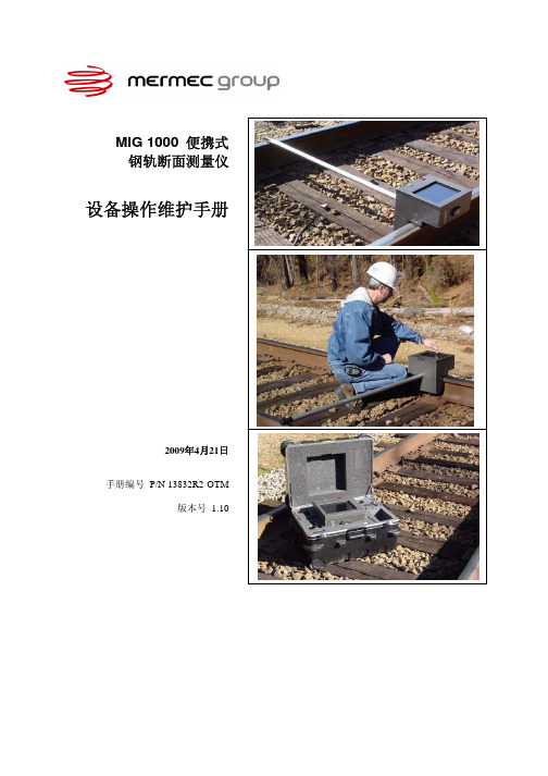
MIG 1000 便携式钢轨断面测量仪设备操作维护手册2009年4月21日手册编号 P/N 13832R2-OTM版本号 1.10版权所有。
本文档所包含信息受版权保护。
未经MERMEC Group公司许可,不得对本文档任何部分进行复制、保存以及通过任意形式的传播(包括电子、机械、印刷等等)。
本文档所含信息被认为是真实可靠的。
本公司对设备的使用,以及因为设备引起的版权冲突和任何第三方的其他权利不承担责任。
MIG 1000 是MERMEC Group公司的注册商标.Windows 2000和Windows XP是微软公司的注册商标. 本文档中其他任何商标均来自各自的制造商.© Copyright 2006-2009 by MERMEC Group 版权所有,违者必究.MERMEC Groupvia Oberdan,7070043 Monopoli (BA)Italy080 8876570PROPRIETARY INFORMATION:This document contains information proprietary to MERMEC Group This information may not be distributed without the written authorization of an officer of MERMEC Group 目录第一章介绍1.1 概述..........................................................................................................................1-11.2 测量技术..................................................................................................................1-11.3 应用..........................................................................................................................1-11.3.1 标准钢轨对比................................................................................................1-21.3.2 轨型“前后” 对比...........................................................................................1-21.3.3 打磨断面对比................................................................................................1-3第二章使用安全2.1 警告..........................................................................................................................2-12.2 产品标签..................................................................................................................2-12.2.1 出光孔标签....................................................................................................2-22.2.2 认证标签........................................................................................................2-32.2.3 警告标签........................................................................................................2-32.2.4 厂商信息标签................................................................................................2-32.3 安全装置..................................................................................................................2-32.4 激光功率..................................................................................................................2-4第三章操作3.1 设备安装..................................................................................................................3-13.1.1 无护轨安装....................................................................................................3-23.1.2 有护轨安装....................................................................................................3-33.1.3 正线磨损严重并有护轨时的安装................................................................3-43.2 启动系统..................................................................................................................3-43.3 采集断面..................................................................................................................3-53.4 编辑断面..................................................................................................................3-53.5 保存断面..................................................................................................................3-63.6 查看已保存断面......................................................................................................3-63.7 定义对比断面..........................................................................................................3-63.8 更改阈值设定..........................................................................................................3-7Table of ContentsPROPRIETARY INFORMATION: This document contains information proprietary to MERMEC Group This information may not be distributed without the written authorization of an officer of MERMEC Group 3.9 将断面数据复制到台式机.......................................................................................3-73.9.1 USB 连接........................................................................................................3-83.9.2 串口连接........................................................................................................3-83.10 电池充电................................................................................................................3-8第四章 MIG 1000 的菜单4.1 菜单列表..................................................................................................................4-1 4.2 文本和数字输入......................................................................................................4-5 4.3 主菜单......................................................................................................................4-7 4.4 断面屏幕..................................................................................................................4-8 4.5 回放屏幕..................................................................................................................4-9 4.5.1 钢轨类型选择菜单......................................................................................4-12 4.5.2 断面和回放缩放屏幕..................................................................................4-13 4.5.3 对比断面调整..............................................................................................4-14 4.5.3.1 标准对比断面调整........................................................................4-14 4.5.3.2 打磨对比断面调整........................................................................4-14 4.5.4 事件输入屏幕..............................................................................................4-15 4.5.5 举例-打磨对比断面..................................................................................4-16 4.6 设置菜单................................................................................................................4-17 4.6.1 功能菜单......................................................................................................4-18 4.6.1.1 诊断菜单........................................................................................4-20 4.6.2 打磨图菜单..................................................................................................4-21 4.6.2.1 轨头坐标-距离............................................................................4-21 4.6.2.2 轨头坐标-角度............................................................................4-21 4.6.2.2.1 公差表菜单......................................................................4-24 4.6.3 自动事件菜单..............................................................................................4-26 4.6.4 编辑事件标签菜单......................................................................................4-27 4.6.4.1 事件类别选择................................................................................4-28 4.7 文件管理菜单........................................................................................................4-29 4.7.1 文件选择菜单..............................................................................................4-30 4.7.2 文件删除菜单..............................................................................................4-31 4.7.3 文件传输菜单..............................................................................................4-31 4.8 对设备进行软件升级............................................................................................4-31 第五章设备维护 5.1 检查标定..................................................................................................................5-1 5.2 清洁出光孔 ............................................................................................................5-3 5.3 清洁显示器 .............................................................................................................5-3 5.4 清洁金属外壳 .........................................................................................................5-3 第六章维修服务 6.1 厂商服务..................................................................................................................6-1Table of Contents第七章运输与储存7.1 储存箱......................................................................................................................7-17.2 运输措施..................................................................................................................7-2第八章 Windows2000/XP软件8.1 软件安装..................................................................................................................8-18.1.1 WinEZ3..........................................................................................................8-18.1.2 对比断面........................................................................................................8-28.2 文件选择菜单..........................................................................................................8-28.3 WinEZ3主界面.........................................................................................................8-38.3.1 断面窗口........................................................................................................8-38.3.2 打磨窗口........................................................................................................8-48.3.3 主工具栏........................................................................................................8-58.4 WinEZ3对话窗口.....................................................................................................8-68.4.1 打印窗口........................................................................................................8-68.4.2 文件传输窗口................................................................................................8-78.4.2.1 串口连接模式..................................................................................8-78.4.2.2 压缩模式..........................................................................................8-88.4.2.3 USB连接模式..................................................................................8-88.4.3 事件窗口........................................................................................................8-98.4.3.1 编辑事件类别..................................................................................8-98.4.3.2 编辑事件标签..................................................................................8-98.4.3.3 增加事件..........................................................................................8-98.5 手工对齐................................................................................................................8-108.6 公差表....................................................................................................................8-118.6.1 增加新表......................................................................................................8-128.6.2 删除表..........................................................................................................8-128.6.3 移动表..........................................................................................................8-128.7 WinEZ3菜单结构...................................................................................................8-138.8 环境参数设置........................................................................................................8-158.9 Ascii选项................................................................................................................8-15附录 A 系统技术规范A.1 尺寸及重量.............................................................................................................A-1A.2 温度.........................................................................................................................A-1A.3 功率.........................................................................................................................A-1A.4 数据存储.................................................................................................................A-1A.5 处理器.....................................................................................................................A-2A.6 激光器.....................................................................................................................A-2A.7 视频照相机.............................................................................................................A-2A.8 附件产品号.............................................................................................................A-2PROPRIETARY INFORMATION:This document contains information proprietary to MERMEC Group This informationmay not be distributed without the written authorization of an officer of MERMEC GroupTable of Contents附录 B 断面轮廓说明B.1 测量点.....................................................................................................................B-1B.2 断面轮廓的重叠.....................................................................................................B-1B.3 轮廓线缺失.............................................................................................................B-1B.4 打磨专用模板.........................................................................................................B-1B.5 标定检查部件.........................................................................................................B-2附录 C 故障检修手册C.1 试图采集断面时出错.............................................................................................C-1C.2 文件传输的故障检修.............................................................................................C-2PROPRIETARY INFORMATION:This document contains information proprietary to MERMEC Group This informationmay not be distributed without the written authorization of an officer of MERMEC Group文档图片列表图 1-1. 标准钢轨对比..........................................................................................1-2 图 1-2. 两点对齐打磨断面..................................................................................1-3 图 1-3. 带有打磨角度的断面对比. ...................................................................1-4 图 1-4. 带有公差表的断面对比..........................................................................1-4图 2-1. 标签位置..................................................................................................2-2 图 2-2. 出光孔标签..............................................................................................2-2 图 2-3. 认证标签..................................................................................................2-3 图 2-4. 警告标签..................................................................................................2-3 图 2-5. 厂商信息标签..........................................................................................2-3图 3-1. MIG 1000放置在无护轨钢轨上.............................................................3-2 图 3-2. MIG 1000放置在有护轨钢轨上.............................................................3-3 图 3-3. MIG 1000放置在有护轨且正线磨损严重的钢轨上.............................3-4 图 3-4. MIG 1000终端连接.................................................................................3-7图 4-1. 文本输入..................................................................................................4-5 图 4-2. 数字键盘..................................................................................................4-6 图 4-3. 主菜单......................................................................................................4-7 图 4-4. 断面屏幕..................................................................................................4-8 图 4-5. 回放屏幕#1..............................................................................................4-9 图 4-6. 回放屏幕#2............................................................................................4-11 图 4-7. 钢轨类型选择菜单................................................................................4-12 图 4-8. 缩放-标准断面对比............................................................................4-13 图 4-9. 缩放-打磨断面对比............................................................................4-13 图 4-10. 对比断面调整屏幕................................................................................4-14 图 4-11. 事件输入屏幕........................................................................................4-15 图 4-12. 回放屏幕-打磨对比断面....................................................................4-16 图 4-13. 设置菜单................................................................................................4-17 图 4-14. 功能菜单................................................................................................4-18 图 4-15. 诊断菜单................................................................................................4-20PROPRIETARY INFORMATION:This document contains information proprietary to MERMEC Group This informationmay not be distributed without the written authorization of an officer of MERMEC GroupList of Figures图 4-16. 打磨图菜单............................................................................................4-21 图 4-17. 打磨图菜单-角度................................................................................4-22 图 4-18. 角度测量打磨对比断面........................................................................4-23 图 4-19. 角度测量公差表菜单............................................................................4-24 图 4-20. 含公差表打磨对比断面........................................................................4-25 图 4-21. 自动标志菜单........................................................................................4-26 图 4-22. 编辑事件标签菜单................................................................................4-27 图 4-23. 事件类别菜单........................................................................................4-28 图 4-24. 文件管理菜单........................................................................................4-29 图 4-25. 文件选择菜单........................................................................................4-30 图 4-26. 文件删除菜单........................................................................................4-31图 5-1. 安装标定检查块......................................................................................5-2图 7-1. MIG 1000及储存箱.................................................................................7-1图 7-2. 储存箱分布图..........................................................................................7-2图 C-1. 一个良好的断面.....................................................................................C-2PROPRIETARY INFORMATION:This document contains information proprietary to MERMEC Group This informationmay not be distributed without the written authorization of an officer of MERMEC Group第一章介绍1.1 概述MIG 1000是一套用来测量钢轨接触面的便携式设备,是一套可以用电池驱动的、手持式的、能提供准确可靠的、非接触式钢轨断面的设备。
调频1KW发射机技术说明书

+10dBm;
第6页
GME1F13D 调频发射机技术说明书
第三章 发射机面板与接口说明 第一节 前面板
从发射机的前方,从上到下分别是: [1] 主控制单元(显示单元) [2] 激励器 [3] 电控单元 [4] 功放单元 [5] 开关电源
1 2 3
4
5
图 3-1
第7页
各部分前面板具体说明如下:
一、电源面板说明
北京吉兆电子有限公司
GME1F13 调频 1KW 发射机技术说明书
公司地址
售后服务热线 免费咨询热线 营销部电话 营销部传真 E-mail Web
北京市海淀区王庄路 1 号 清华同方科技大厦 A 座 26 层
(100083) 010-82916768 010-800-810-8463 010-82399620 010-82399617 gme@
五、激励器、功放均带有检测、控制接口,可以根据用户要求增加控制单 元,实现微机联网控制,并实现遥控开关机、定时开关机等功能。
六、具有防雷击、交流欠压、直流过压、电源过热、功放过热、发射机超 载等各种保护功能,使发射机性能稳定可靠。
七、功放具有很强的自保护功能,在出现功放过热、激励器过激励、天线 超载时,功放中的控制电路可以立即作出判断,并作出相应的动作关 断信号保护功放。
相对湿度:≤ 95%; 海拔高度:≤2000 米; *输 入 特 性 [1]音频输入阻抗:600Ω(平衡)或 10KΩ可选 [2]音 频 输 入 接 口 : XLR [3]音频输入电平:-13dBm---- +14dBm; [4]MPX 输入接口:BNC 、不平衡 [5]SCA/RDS 输入接口:BNC、不平衡
第5页
GME1F13D 调频发射机技术说明书
凯恩帝100tid参数说明

凯恩帝100tid参数说明(原创版)目录1.凯恩帝 k1000ti 说明书参数篇概述2.凯恩帝 k1000ti 参数说明书的内容3.凯恩帝 k1000ti 参数备份的操作方法4.凯恩帝 k1000ti-d 说明书的应用5.学习凯恩帝 k1000ti 说明书的意义正文一、凯恩帝 k1000ti 说明书参数篇概述凯恩帝 k1000ti 是一种数控车床,其参数说明书对于操作者来说至关重要。
本文将介绍凯恩帝 k1000ti 参数说明书的内容,以及如何进行参数备份和应用。
二、凯恩帝 k1000ti 参数说明书的内容凯恩帝 k1000ti 参数说明书主要包括以下内容:1.控制系统的概述,包括凯恩帝 k1000ti 的控制系统类型、功能和特点。
2.凯恩帝 k1000ti 的基本参数,包括机床型号、尺寸、加工范围等。
3.凯恩帝 k1000ti 的详细参数,包括各个轴的参数、主轴参数、刀具参数等。
4.凯恩帝 k1000ti 的接口和通信,包括与外部设备的接口和通信方式。
5.凯恩帝 k1000ti 的编程和操作,包括编程语言、编程方法和操作步骤。
三、凯恩帝 k1000ti 参数备份的操作方法凯恩帝 k1000ti 参数备份的操作方法如下:1.打开凯恩帝 k1000ti 控制系统。
2.选择“参数备份”菜单。
3.选择要备份的参数类型,例如基本参数、详细参数等。
4.将参数备份到 U 盘或其他存储设备上。
5.关闭凯恩帝 k1000ti 控制系统。
四、凯恩帝 k1000ti-d 说明书的应用凯恩帝 k1000ti-d 说明书主要用于指导操作者如何使用凯恩帝k1000ti 数控车床,包括编程、操作、维护和故障排除等。
通过学习凯恩帝 k1000ti-d 说明书,操作者可以提高数控机床的操作水平和编程能力。
《射频功率放大器》课件第2章

图2.3.3 MMG3003NT1工作在3.4~3.6 GHz的应用电路 (a) 工作在3.4~3.6 GHz频率范围的电原理图; (b) 元器件布局图
2.4 MMG3005NT1 400~2400 MHz功率放大器
MMG3005NT1 是一个A类、宽带、小信号、高线性的 晶体管放大器芯片。其输入、输出内部匹配为50 Ω;工作频 率范围为400~2400 MHz;输出功率(P1 dB)为30 dBm;小 信号增益为15 dB; 输出三阶截点为48 dBm (@2140 MHz); 噪声系数为6 dB; 电源电压为5 V; 电流消耗为500 mA。
MMG3003NT1 是一个A类、宽带、小信号、高线性的 晶体管放大器芯片。其输入、输出内部匹配为50 Ω;工作频 率范围为40~3600 MHz;输出功率(P1 dB)为24 dBm;小 信号增益为19.3~20 dB;输出三阶截点为40.5 dBm(@900 MHz);噪声系数为 4 dB;电源电压为6.2 V;电流消耗为 160~205 mA。
6.0 GHz功率放大器
MMG3007/08/09/10/11/12/13NT1 是一种A类、宽带、小 信号、高线性的晶体管放大器芯片。其输入、输出内部匹配 为50 Ω,工作频率范围为0~6 GHz。
MMG3007 NT1输出功率(P1 dB)为16 dBm;小信号增益 为18~19 dB;输出三阶截点为30 dBm(@900 MHz);噪声 系数为3.8 dB;电源电压为5 V; 电流消耗为39~55 mA。
MMG3007/08/09/10/11/12/13NT1采用SOT-89(CASE 1514-01,STYLE 1)封装(见图2.2.1),引脚端1为射频输入端, 引脚端2为接地端,引脚端3为功率放大器输出和直流电源端。
电导率中文资料

安全须知
这台仪器是建立和测试交流电源线ING EN 61326和包装技术安全条件。 为了保持这种状况,以确保安全运行,用户必须按照该指令中给出的 提示和警告。
警告 在安装过程中必须遵守相关国家规定。 忽略警告可能会导致严重的人生伤害或重大财产损失。
该产品必须由具备相关工作经验的人员操作。 正确和安全地操作本设备依赖于恰当的运输,储存,安装和操作。
设定旋钮能比较简单的来设定测量范围温度系数以及温度输出范围详细说明请参阅配置显示屏9999mscm13990001mscm0001最大范围最小范围调节旋钮电导率版本左右旋确认菜单左右旋技术数据传感器感应式双电感感应式过程连接g1锥面密封绝缘材料peek电气连接电缆密封接头m16pgm12插针黄铜镀镍机械数据壳体不锈钢w14301aisi304过程连接不锈钢w14404aisi316l防护等级ip67介质压力max
所有的电气接线都必须符合现场相关要求。 为了防止电磁干扰,我们推荐使用双绞线和屏蔽电缆, 保持电源和信号线分层。连接的时候必须根据接线图。
警告 对于电气的防爆设备的安装和调试, 合格证书中给出的数据也爆炸保护区域内的电气设备的安装必须考虑的地方法规。 本设备安全的版本,可以安装在爆炸中冒险区域, 根据安全规范只连接到一个本质安全型供电回路与相应的电气值。
测量介质流经通道孔( 3)中的测量头形式的导体回路, 连接在所述初级环形电感(1)和次级环形电感(2)的初级侧的之间。 的输出电流与介质的导电性成比例关系。信号调理,放大和转换提供了一个 D / A转换器带隔离的4 ... 20 mA信号输出
测得的电导率介质温度是非常可靠的。 因此测量时能够得到前端(4)非常的迅速的温度补偿
mS/cm
0.001 0.001 0.01 0.01 0.01 0.1 0.1 0.1 0.1 1.0 1.0 1.0 1.0 1.0
米格驱动器mg1000中文说明书

米格驱动器mg1000中文说明书米格驱动器mg1000是一款专为实现数据的快速可靠传输而设计的便携式、智能电源系统。
其具有高速度、低功耗、高安全性等特点。
具有优良的电源稳定性、高性价比等特点。
产品体积小巧,方便携带;可进行智能化数据传输;无需昂贵的电源开关和相关电路。
1、适用于汽车、计算机、游戏机及其配套设备,如液晶显示器;其他如打印机、排练机、数码相机等。
使用方法:本产品为数字无线控制产品,可通过外接 USB接口或无线控制器连接,进行无线数据传输。
如需使用笔记本电脑远程控制时,通过手机远程控制即可2、适用于需要可靠稳定电源的场合,如便携式计算机;该系统采用低电压输出,并具有极低功耗。
当电池电量不足时;可通过自动模式(Detection)或低功耗模式(Low Light)切换到低电压模式;此系统的输出电压和输出电流都是可调的;其输出电流恒定在±5%-10%范围内内。
3、可用作通设备的充电器及 USB充电接口;具有高速,稳定,耐用的特性。
同时,在手机,平板电脑,车载电子设备等通讯设备上均可使用。
可提供无线充电的功能,可将手机,平板电脑和车载电子设备的电源自动连接到该电源上进行充电。
4、可使用于多种不同环境;用户可根据需要,进行更多个性化定制。
系统使用时,用户可根据系统自身的需求,设定合适的参数值,然后通过软件自动完成该参数的设定;再根据实际的工作状态,将参数设定到合适的数值范围内。
米格驱动器mg1000可以用来直接进行数据传输和控制。
5、具有高安全性与电源管理功能。
在电源电路出现异常时,会自动断电。
具有过压和过流保护功能。
同时,该产品还具有漏电保护功能,可以有效防止因设备漏电导致的安全事故问题的发生。
- 1、下载文档前请自行甄别文档内容的完整性,平台不提供额外的编辑、内容补充、找答案等附加服务。
- 2、"仅部分预览"的文档,不可在线预览部分如存在完整性等问题,可反馈申请退款(可完整预览的文档不适用该条件!)。
- 3、如文档侵犯您的权益,请联系客服反馈,我们会尽快为您处理(人工客服工作时间:9:00-18:30)。
Will be replaced by MMG1001NT1 in Q305. N suffix indicates 260°C reflow capable.The PFP-16 package has had lead-free terminations from its initial release.Gallium ArsenideCATV Integrated Amplifier ModuleFeatures•Specified for 79-, 112- and 132-Channel Loading•Excellent Distortion Performance•Built-in Input Diode Protection•GaAs FET Transistor Technology•Unconditionally Stable Under All Load Conditions•In Tape and Reel. R2 Suffix = 1,500 Units per 16 mm, 13 inch Reel.T1 Suffix = 1,000 Units per 16 mm, 13 inch Reel.Applications•CATV Systems Operating in the 40 to 870 MHz Frequency Range•Input Stage Amplifier in Optical Nodes, Line Extenders and TrunkDistribution Amplifiers for CATV Systems•Output Stage Amplifier on Applications Requiring Low Power Dissipationand High Output Performance•Driver Amplifier in Linear General Purpose ApplicationsDescription•24 Vdc Supply or 12 Vdc Supply with Bias Change, 40 to 870 MHz, CATVIntegrated Forward Amplifier ModuleTable 1. Maximum RatingsRating Symbol Value Unit RF Voltage Input (Single T one)V in+65dBmV DC Supply Voltage24 V Application12 V ApplicationV CC+26+14VdcOperating Case T emperature Range T C-20 to +100°C Storage T emperature Range T stg-40 to +100°C Table 2. Thermal CharacteristicsCharacteristic Symbol Value Unit Thermal Resistance, Junction to Case RθJC 6.6°C/WDocument Number: MMG1001Rev. 5, 7/2005 Freescale SemiconductorTechnical Data2RF Device DataFreescale SemiconductorMMG1001R2 MMG1001T1Table 3. ESD Protection CharacteristicsTest ConditionsClass Human Body Model 1 (minimum)Machine Model M1 (minimum)Charge Device ModelC5 (minimum)Table 4. Moisture Sensitivity LevelTest MethodologyRating Package Peak TemperatureUnit Per JESD 22-A113, IPC/JEDEC J-STD-0203260°CTable 5. Electrical Characteristics for 24 V Application (V CC = 24 Vdc, T C = +30°C, 75 Ω system unless otherwise noted)CharacteristicSymbol Min Typ Max Unit Frequency Range BW 40—870MHz Power Gain 50 MHz 870 MHz G p ——1819——dB Slope40-870 MHzS —0.6—dB Gain Flatness (40-870 MHz, Peak to Valley)G F —0.5—dB Input Return Loss (Z o = 75 Ohms)f = 40-160 MHz f = 161-450 MHz f = 451-870 MHzIRL——211922———dBOutput Return Loss (Z o = 75 Ohms)f = 40-400 MHz f = 401-870 MHz ORL——2217——dBComposite Second Order(V out = +44 dBmV/ch., Worst Case)132-Channel FLAT (V out = +46 dBmV/ch., Worst Case)112-Channel FLAT (V out = +48 dBmV/ch., Worst Case)79-Channel FLAT CSO 132CSO 112CSO 79———-65-65-71-58-59-62dBcCross Modulation Distortion @ Ch 2(V out = +44 dBmV/ch., FM = 55 MHz)132-Channel FLAT (V out = +46 dBmV/ch., FM = 55 MHz)112-Channel FLAT (V out = +48 dBmV/ch., FM = 55 MHz)79-Channel FLAT XMD 132XMD 112XMD 79———-64-63-62-52-52-52dBcComposite Triple Beat(V out = +44 dBmV/ch., Worst Case)132-Channel FLAT (V out = +46 dBmV/ch., Worst Case)112-Channel FLAT (V out = +48 dBmV/ch., Worst Case)79-Channel FLAT CTB 132CTB 112CTB 79———-63-64-65-56-56-58dBcNoise Figure50 MHz 870 MHzNF ——44 5.05.0dB DC Current (V DC = 24 V, T C = -20°to +100°C)I DC230250265mA (continued)MMG1001R2 MMG1001T13RF Device DataFreescale SemiconductorTable 4. Electrical Characteristics for 12 V Application (V CC = 12 Vdc, T C = +30°C, 75 Ω system unless otherwise noted) (continued)CharacteristicSymbol Min Typ Max Unit Frequency Range BW 40—870MHz Power Gain 50 MHz 870 MHz G p ——1819——dB Slope40-870 MHzS —0.6—dB Gain Flatness (40-870 MHz, Peak to Valley)G F —0.5—dB Input Return Loss (Z o = 75 Ohms)f = 40-160 MHz f = 161-450 MHz f = 451-870 MHzIRL——211919———dBOutput Return Loss (Z o = 75 Ohms)f = 40-400 MHz f = 401-750 MHz f = 751-870 MHz ORL———191715———dBComposite Second Order(V out = +42 dBmV/ch., Worst Case)112-Channel FLAT (V out = +42 dBmV/ch., Worst Case)79-Channel FLAT CSO 112CSO 79——-65-71——dBcCross Modulation Distortion @ Ch 2(V out = +42 dBmV/ch., FM = 55 MHz)112-Channel FLAT (V out = +42 dBmV/ch., FM = 55 MHz)79-Channel FLAT XMD 112XMD 79——-63-62——dBcComposite Triple Beat(V out = +42 dBmV/ch., Worst Case)112-Channel FLAT (V out = +42 dBmV/ch., Worst Case)79-Channel FLAT CTB 112CTB 79——-64-65——dBcNoise Figure50 MHz 870 MHzNF ——44 5.05.0dB DC Current (V DC = 12 V, T C = -20°to +100°C)I DC190210225mA4RF Device DataFreescale SemiconductorMMG1001R2 MMG1001T1Table 6. MMG1001 50-870 MHz Test Circuit Component Designations and ValuesDesignation Description (24 V Application)Description (12 V Application)C1, C7, C8, C11220 pF Chip Capacitors (0603)220 pF Chip Capacitors (0603)C2, C3, C4, C9, C100.01 m F Chip Capacitors (0603)0.01 m F Chip Capacitors (0603)C5, C6 1.8 pF Chip Capacitors (0603) 1.8 pF Chip Capacitors (0603)C12 5.6 pF Chip Capacitor (0603) 5.6 pF Chip Capacitor (0603)D1 5.1 V Zener Diode, On/MM3Z5V1T1 5.1 V Zener Diode, On/MM3Z5V1T1D227 V Zener Diode, On/MM3Z27VT127 V Zener Diode, On/MM3Z27VT1D3Transient Voltage Suppressor,On/1.5k27A/1.5SMC27A T3Transient Voltage Suppressor,On/1.5k27A/1.5SMC27A T3L1, L222 nH Chip Inductors (0603)22 nH Chip Inductors (0603)Q1, Q2Dual Transistors Package, On/MBT3904DW1T1Dual Transistors Package, On/MBT3904DW1T1R1 2.2 k W , 1/4 W Chip Resistor (1206)820 W , 1/4 W Chip Resistor (1206)R2560 W Chip Resistor (0603)560 W Chip Resistor (0603)R382 W Chip Resistor (0603)40 W Chip Resistor (0603)R4820 W Chip Resistors (0603)150 W Chip Resistors (0603)R5820 W Chip Resistors (0603)100 W Chip Resistors (0603)R6120 W Chip Resistor (0603)120 W Chip Resistor (0603)R7 1.5 k W Chip Resistor (0603) 1.5 k W Chip Resistor (0603)R812 W , 1 W Chip Resistor (2512) 4.8 W , 1 W Chip Resistor (2512)R9, R10, R15470 W Chip Resistors (0603)470 W Chip Resistors (0603)R11, R1218 W Chip Resistors (0603)18 W Chip Resistors (0603)R13, R14910 W Chip Resistors (0603)910 W Chip Resistors (0603)R16 2 k W Chip Resistor (0603) 2.7 k W Chip Resistor (0603)R17 6.2 k W Chip Resistor (0603) 6.2 k W Chip Resistor (0603)R1815 W Chip Resistor (0603)15 W Chip Resistor (0603)R190 W Chip Resistor (0603)0 W Chip Resistor (0603)T1Input Transformer , Mot/77PC016E068Input Transformer , 77PC016E068T2Output Transformer , Mot/77PC016E061Output Transformer , 77PC016E061PCBFR4, 62 mil, εr = 4.81FR4, 62 mil, εr = 4.81MMG1001R2 MMG1001T15RF Device DataFreescale SemiconductorFigure 4. MMG1001 50-870 MHz Test Circuit Component LayoutCC = 24 VCC = 12 VFreescale has begun the transition of marking Printed Circuit Boards (PCBs) with the Freescale Semiconductor signature/logo. PCBs may have either Motorola or Freescale markings during the transition period. These changes will have no impact on form, fit or function of the current product.6RF Device Data Freescale SemiconductorMMG1001R2 MMG1001T1TYPICAL CHARACTERISTICS FOR 24 V APPLICATION−75−60CTB,COMPOSITETRIPLEBEAT(dBc)−65−70−85−65CSO,COMPOSITESECONDORDER(dBc)−70−75−80600−75−55f, FREQUENCY (MHz)Figure 7. Cross Modulation Distortion versusFrequencyXMD,CROSSMODULATIONDISTORTION(dBc)−60−65−70400200MMG1001R2 MMG1001T17RF Device DataFreescale SemiconductorPACKAGE DIMENSIONSCASE 978-03ISSUE CDETAIL YPFP-16Information in this document is provided solely to enable system and softwareimplementers to use Freescale Semiconductor products. There are no express orimplied copyright licenses granted hereunder to design or fabricate any integratedcircuits or integrated circuits based on the information in this document.Freescale Semiconductor reserves the right to make changes without further notice toany products herein. Freescale Semiconductor makes no warranty, representation orguarantee regarding the suitability of its products for any particular purpose, nor doesFreescale Semiconductor assume any liability arising out of the application or use ofany product or circuit, and specifically disclaims any and all liability, including withoutlimitation consequential or incidental damages. “Typical” parameters that may beprovided in Freescale Semiconductor data sheets and/or specifications can and dovary in different applications and actual performance may vary over time. All operatingparameters, including “Typicals”, must be validated for each customer application bycustomer’s technical experts. Freescale Semiconductor does not convey any licenseunder its patent rights nor the rights of others. Freescale Semiconductor products arenot designed, intended, or authorized for use as components in systems intended forsurgical implant into the body, or other applications intended to support or sustain life,or for any other application in which the failure of the Freescale Semiconductor productcould create a situation where personal injury or death may occur. Should Buyerpurchase or use Freescale Semiconductor products for any such unintended orunauthorized application, Buyer shall indemnify and hold Freescale Semiconductorand its officers, employees, subsidiaries, affiliates, and distributors harmless against allclaims, costs, damages, and expenses, and reasonable attorney fees arising out of,directly or indirectly, any claim of personal injury or death associated with suchunintended or unauthorized use, even if such claim alleges that FreescaleSemiconductor was negligent regarding the design or manufacture of the part.Freescale t and the Freescale logo are trademarks of Freescale Semiconductor, Inc.All other product or service names are the property of their respective owners.Freescale Semiconductor, Inc. 2005. All rights reserved.How to Reach Us:Home Page:E-mail:support@USA/Europe or Locations Not Listed:Freescale SemiconductorT echnical Information Center, CH3701300 N. Alma School RoadChandler, Arizona 85224+1-800-521-6274 or +1-480-768-2130support@Europe, Middle East, and Africa:Freescale Halbleiter Deutschland GmbHT echnical Information CenterSchatzbogen 781829 Muenchen, Germany+44 1296 380 456 (English)+46 8 52200080 (English)+49 89 92103 559 (German)+33 1 69 35 48 48 (French)support@Japan:Freescale Semiconductor Japan Ltd.HeadquartersARCO T ower 15F1-8-1, Shimo-Meguro, Meguro-ku,T okyo 153-0064Japan0120 191014 or +81 3 5437 9125support.japan@Asia/Pacific:Freescale Semiconductor Hong Kong Ltd.T echnical Information Center2 Dai King StreetT ai Po Industrial EstateT ai Po, N.T., Hong Kong+800 2666 8080@For Literature Requests Only:Freescale Semiconductor Literature Distribution CenterP.O. Box 5405Denver, Colorado 802171-800-441-2447 or 303-675-2140Fax: 303-675-2150LDCForFreescaleSemiconductor@。