SCC05D中文资料
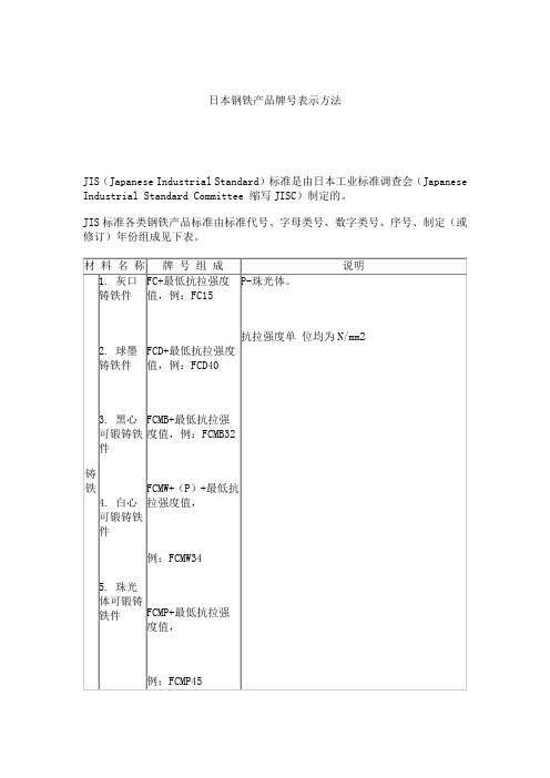
日本钢铁产品牌号表示方法讲解
结构用高强度锰钢铸件
结构用高强度锰铬钢铸件
高锰钢铸件
结构用高强度锰钼钢铸件
锅炉及压力容器用铬钼合金钢板
结构用高强度镍铬钼钢铸件
波纹钢管
波纹钢管
波纹钢管
深冲用冷轧碳钢薄板及带
非时效性深冲冷轧碳钢薄板及带
机动车用成型性好的冷轧高强度钢板及钢带
机动车用成型性好的热轧高强度钢板及钢带
建筑用镀银薄钢板
压力容器用调质合金钢锻件
高压气罐用钢板及钢带
磨光钢棒用一般碳素钢钢材
NCF××TF
NCF××TP
P×××
00P×××
S××
S××F
SBV
S××C
SXXC?CSP
SA×C
SACM
SA×D
SA×E
SAPH
SB
SB?M
SBC
SBPD
SBPR
SC
SCC
SCCrM
SCG
SCH
SCM
SCMn
SCMnCr
SCMnH
瓦垄钢板
电镀锌薄钢板及钢带(抗拉试验)
电镀锌冷轧冲压薄钢板及钢带
非时效冲压冷轧电镀锌薄钢板及钢带
电镀锌热轧薄钢板及钢带
冲压电镀锌热轧薄钢板及钢带
深冲压电镀锌热轧薄钢板及钢带
中常温压力容器用高强度钢板
碳素钢锻件
碳素钢锻件用坯
一般用铬钼钢锻件
低温压力容器用锻件
一般用镍铬钼钢锻件
高温压力容器用合金钢锻件
压力容器用碳素钢铸件
预应力钢筋混凝土用钢丝和钢绞线(圆线)
冷顶锻用碳钢线材
高碳钢盘条
低碳钢盘条
琴钢丝用盘条
涂药电焊条芯用盘条
涂药电焊条芯线
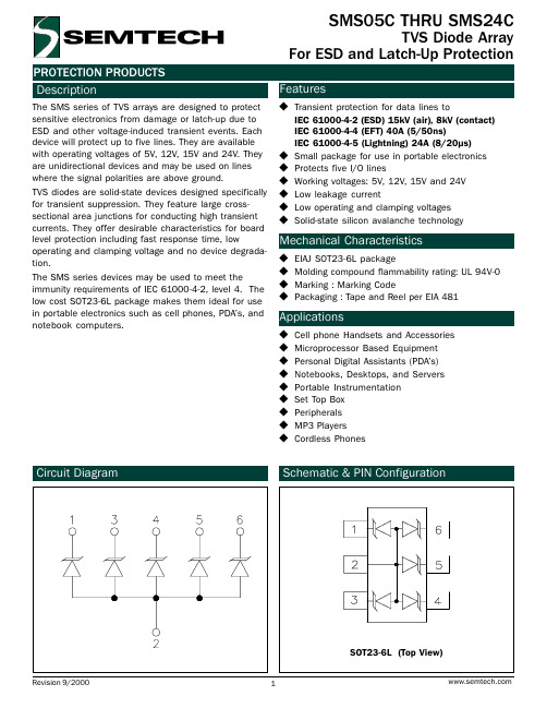
SMS05C中文资料
110 100
90 80 70 60 50 40 30 20 10
0 0
25
50
75
100
125
150
Ambient Temperature - TA (oC)
Clamping Voltage vs. Peak Pulse Current
Clamping Voltage - VC (V)
45
40 SMS24C
Non-Repetitive Peak Pulse Power vs. Pulse Time
10
Peak Pulse Power - PPP (kW)
1
0.1
Percent of IPP
0.01 0.1
110 100
90 80 70 60 50 40 30 20 10
0 0
1
10
100
Pulse Duration - tp (µs)
SMS15C Parameter
Reverse Stand-Off Voltage Reverse Breakdown Voltage Reverse Leakage Current Clamping Voltage Clamping Voltage Junction Capacitance
Symbol VRWM VBR IR VC VC Cj
Minimum
It = 1mA
6
VRWM = 5V, T=25°C
IPP = 5A, tp = 8/20µs
IPP = 24A, tp = 8/20µs
Between I/O Pins and Gnd
VR = 0V, f = 1MHz
Typical 325
C500-IDA02;中文规格书,Datasheet资料

Visual Aids
The following headings appear in the left column of the manual to help you locate different types of information. Note Indicates information of particular interest for efficient and convenient operation of the product.
/
/
!
Notice:
OMRON products are manufactured for use according to proper procedures by a qualified operator and only for the purposes described in this manual. The following conventions are used to indicate and classify warnings in this manual. Always heed the information provided with them. DANGER! Indicates information that, if not heeded, could result in loss of life or serious injury.
SCC100A中文资料

FEATURESPRESSURE SENSOR CHARACTERISTICSPart NumberSCC05(D,G)SCC15A SCC15(D,G)SCC30(A,D,G)SCC100A SCC100(D,G)9SCC300APerformance Characteristics (Individual Models) I S = 1.0 mA, T A = 25°C 1Operating Pressure Range0-5 psid(g)0-15 psia 0-15 psid(g)0-30 psid(g)0-100 psia 0-100 psig 0-300 psiaMaximum Over Pressure20 psi 30 psia 30 psi 60 psi 150 psia 150 psig 450 psiaAccuracy 20.50%0.50%0.50%0.50%0.50%0.50%0.50%Effect On Span 3(0°C-50°C)1.50%1.50%1.50%1.50%1.50%1.50%1.50%Effect On Offset 4(0°C-50°C)2.00%2.00%2.00%2.00%2.00%2.00%2.00%Full-Scale Span 5(mV)25-6530-9540-9560-15085-22585-22550-120Performance Characteristics (All Models) I S = 1.0 mA, T A = 25°CCharacteristicsZero Pressure OffsetCombined, Linearity, Hysteresis, Repeatability 2Temperature Effect on Span 3, 8Temperature Effect on Offset 4,8Long T erm Stability of Offset and Span 6Response Time (10% to 90%)7Input Impedance Output ImpedanceMin.-30.0---------------4.004.00Typ.-100.250.250.500.100.105.005.00Max.20.00.501.502.00------6.506.50UnitmV %FSO %FSO %FSO %FSO mSec k Ωk ΩSpecification Notes:1:Reference Conditions: Supply Current = 1.0 mA, T A =25°C, Common-mode Line Pressure = 0 psig, Pressure Applied to P1, unless otherwise noted.2:Accuracy is the sum of Hysterisis and Linearity. Hysterisis is the maximum output difference at any point within the operating pressure range for increasing and decreasing pressure.Linearity refers to the best straight line fit as measured for the offset, full-scale and 1/2 full-scale pressure at 25°C.3:This is the maximum temperature shift for span when measured between 0°C and 50°C relative to the 25°C reading. Typical temperature coefficients for span and resistance are -2200 ppm/°C and +2200 ppm/°C respectively.4:This is the maximum temperature shift for offset when measured between 0°C and 50°C relative to the 25°C reading.5:Span is the algebraic difference between the output voltage at full-scale pressure and the output at zero pressure.6:Maximum difference in output at any pressure with the operating pressure range and temperature within 0°C to 50°C after:a)100 temperature cycles, 0°C to 50°C b) 1.0 million pressure cycles, 0 psi to full-scale span7:Response time for a 0 psi to full-scale span pressure step change. 10% to 90% rise time8:Temp effect on span and offset are guaranteed by design. Therefore these parameters are not 100% tested.9:The SCC100D devices can only be used in a forward gauge mode. Application of more than 30 psig to the back side of any of the SCC Series devices can result in device failure.Maximum Ratings (For All Devices)Supply Current, I S1.5 mATemperature RangesCompensated 0°C to +50°C Operating -40°C to +85°C Storage-55°C to +125°C Humidity0 to 100 %RHLead T emperature (soldering 4 sec)250°C Common-Mode Pressure150 psiPHYSICAL DIMENSIONSButton PackageBasic Sensor DIP "D2" PackagePHYSICAL DIMENSIONS (cont.)Basic Sensor DIP "D4" PackageN PackagePressure RangeAbsolute Pressure0 - 15 psi 0 - 30 psi0 - 100 psi 0 - 300 psiGage Pressure0 - 5 psi 0 - 15 psi 0 - 30 psi 0 - 100 psiDifferential Pressure0 - 5 psi 0 - 15 psi 0 - 30 psi 0 - 100 psi (9)Order Part NumberButton PackageSCC15A SCC30A SCC100A---use differential devices SCC05D SCC15D SCC30D SCC100D"N" Package SCC15AN SCC30AN SCC100AN---use differential devices SCC05DN SCC15DN SCC30DN SCC100DNTO Package SCC15AHO SCC30AHO SCC100AHO SCC300AHO SCC05GSO SCC15GSO SCC30GSO---------------DIP Packagesingle portSCC15AD2SCC30AD2SCC100AD2SCC05GD2SCC15GD2SCC30GD2---------------DIP Package Dual port------------------------SCC05DD4SCC15DD4SCC30DD4SCC100DD4SenSym and Sensortechnics reserve the right to make changes to any products herein. SenSym and Sensortechnics do not assume any liability arising out of the application or use of any product or circuit described herein, neither does it convey any license under its patent rights nor the rights of others.ORDERING INFORMATIONPHYSICAL DIMENSIONS (cont.)AHO Package (TO-5)GSO Package (TO-39)。
74HC595完整中文资料word资料5页
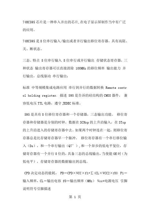
74HC595芯片是一种串入并出的芯片,在电子显示屏制作当中有广泛的应用。
74HC595是8位串行输入/输出或者并行输出移位寄存器,具有高阻、关、断状态。
三态。
特点 8位串行输入 8位串行或并行输出存储状态寄存器,三种状态输出寄存器可以直接清除 100MHz的移位频率输出能力并行输出,总线驱动串行输出;标准中等规模集成电路应用串行到并行的数据转换 Remote contr ol holding register. 描述 595是告诉的硅结构的CMOS器件,兼容低电压TTL电路,遵守JEDEC标准。
595是具有8位移位寄存器和一个存储器,三态输出功能。
移位寄存器和存储器是分别的时钟。
数据在SCHcp的上升沿输入,在STcp 的上升沿进入的存储寄存器中去。
如果两个时钟连在一起,则移位寄存器总是比存储寄存器早一个脉冲。
移位寄存器有一个串行移位输入(Ds),和一个串行输出(Q7’),和一个异步的低电平复位,存储寄存器有一个并行8位的,具备三态的总线输出,当使能OE时(为低电平),存储寄存器的数据输出到总线。
CPD决定动态的能耗, PD=CPD×VCC×f1+∑(CL×VCC2×f0) F1=输入频率,CL=输出电容 f0=输出频率(MHz) Vcc=电源电压引脚说明符号引脚描述内部结构结合引脚说明就能很快理解 595的工作情况引脚功能表:管脚编号管脚名管脚定义功能1、2、3、4、5、6、7、15QA—QH 三态输出管脚8 GND 电源地9 SQH 串行数据输出管脚10 SCLR 移位寄存器清零端11 SCK 数据输入时钟线12 RCK 输出存储器锁存时钟线13 OE 输出使能14 SI 数据线15 VCC 电源端真值表:输入管脚输出管脚SI SCK SCLR RCK OEX X X X H QA—QH 输出高阻X X X X L QA—QH 输出有效值X X L X X 移位寄存器清零L 上沿H X X 移位寄存器存储LH 上沿H X X 移位寄存器存储HX 下沿H X X 移位寄存器状态保持X X X 上沿X 输出存储器锁存移位寄存器中的状态值X X X 下沿X 输出存储器状态保持74595的数据端:QA--QH: 八位并行输出端,可以直接控制数码管的8个段。
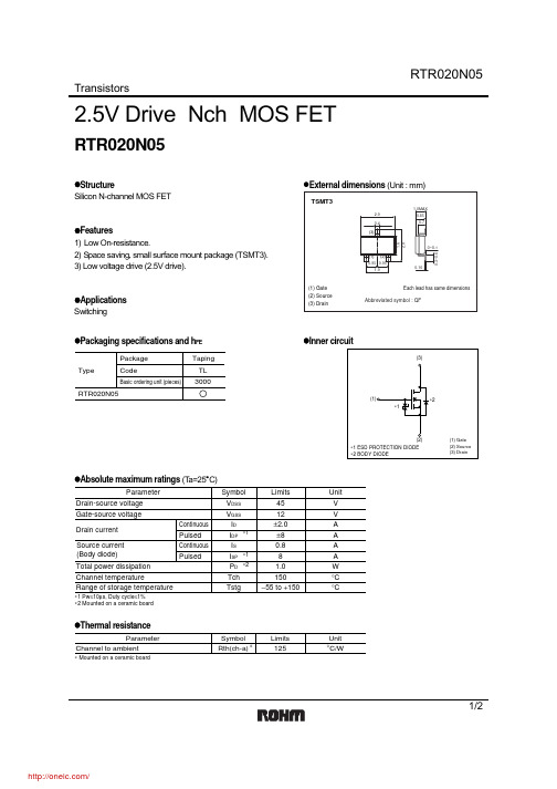
RTR020N05TL;中文规格书,Datasheet资料
The products listed in this document are designed to be used with ordinary electronic equipment or devices (such as audio visual equipment, office-automation equipment, communications devices, electrical appliances and electronic toys). Should you intend to use these products with equipment or devices which require an extremely high level of reliability and the malfunction of with would directly endanger human life (such as medical instruments, transportation equipment, aerospace machinery, nuclear-reactor controllers, fuel controllers and other safety devices), please be sure to consult with our sales representative in advance. About Export Control Order in Japan Products described herein are the objects of controlled goods in Annex 1 (Item 16) of Export Trade Control Order in Japan. In case of export from Japan, please confirm if it applies to "objective" criteria or an "informed" (by MITI clause) on the basis of "catch all controls for Non-Proliferation of Weapons of Mass Destruction.
FA05中文资料
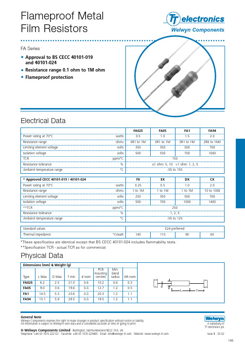
Flameproof MetalFilm ResistorsFA Series•Approval to BS CECC 40101-019 and 40101-024•Resistance range 0.1 ohm to 1M ohm •Flameproof protectionFA025FA05FA1FA94Power rating at 70°C watts 0.5 1.0 1.5 2.0Resistance range ohms 0R1 to 1M 0R1 to 1M 0R1 to 1M 2R6 to 1M0Limiting element voltage volts 350350500700Isolation voltage volts 5005007001000TCRppm/°C150Resistance tolerance %≤1 ohm: 5, 10 >1 ohm: 1, 2, 5Ambient temperature range°C-55 to 155General NoteWelwyn Components reserves the right to make changes in product specification without notice or liability. All information is subject to Welwyn’s own data and is considered accurate at time of going to print.© Welwyn Components Limited · Bedlington, Northumberland NE22 7AA, UKTelephone: +44 (0)1670 822181 · Facsimile: +44 (0)1670 829465 · Email: info@ · Website: Electrical Data* Approved CECC 40101-019 / 40101-024FX EX DX CX Power rating at 70°C watts 0.250.5 1.0 2.0Resistance range ohms 1 to 1M 1 to 1M 1 to 1M 10 to 100kLimiting element voltage volts 250350500700Isolation voltage volts 50070010001400**TCRppm/°C250Resistance tolerance %1, 2, 5Ambient temperature range °C -55 to 125Standard values E24 preferred Thermal impedance°C/watt1401109060Issue B · 03.02A subsidiary of TT electronics plc Welwyn Components145*These specificatios are identical except that BS CECC 40101-024 includes flammability tests.**Specification TCR - actual TCR as for commercial.LDfdDimensions (mm) &Weight (g)PCB Min.mounting bend Type L Max D Max f min d nom centres radius Wt.nom FA025 6.2 2.521.00.610.20.60.3FA059.0 3.619.60.812.7 1.20.5FA114.5 5.323.60.820.3 1.2 1.1FA9413.15.929.50.819.51.21.1Physical DataFlameproof Power Metal Film ResistorsFA Series© Welwyn Components Limited Bedlington, Northumberland NE22 7AA, UKTelephone: +44 (0)1670 822181 · Facsimile: +44 (0)1670 829465 · Email: info@ · Website: Issue B · 03.02Welwyn Components146Application Notes1.If the resistors are to dissipate full rated power, it is recommended that the terminations should not be soldered closer than 4mm from the body.2.Due to operating temperature limitations imposed by some pcb materials, derating may be necessary. An estimate of the temperature rise to be expected can be calculated using the thermal impedance figures given under Electrical Data.bf 1f 266cBody Location f 1 – f 2 ≤ 1.4 mmPackagingAll FA Series resistors are normally supplied tape packed ready for loading onto automatic sequencing and insertion machines.Component wires will not protrude beyond the outside edge of the tapes.Alternative packaging available by request.Lead Formed resistors can also be supplied. Standard options of Lancet, Radial and Goalpost forming are shown in Lead Form Information section.MarkingResistors are colour coded with 4 bands.IEC 62 colours are used.Solvent ResistanceThe body protection and marking are resistant to all normal industrial cleaning solvents suitable for printed circuits.FlammabilityThe resistors will not burn or emit incandescent particles under any condition of applied temperature or power overload.ConstructionThe resistance element is a precisely controlled thin film of metal alloy on a high purity ceramic core, protected by a cement coating applied so that terminations remain completely clear.This permits a well defined body length, (clean lead to clean lead dimension L).TerminationsMaterial Solder-coated copper wire.StrengthThe terminations meet the requirements of IEC 68.2.21Solderability The terminations meet the requirements ofIEC 115-1, Clause 4.17.3.2CECC 40101-019/40101-024Actual Performance RequirementsMaximumTypical Load at commercial rating: 1000 hrs at 70°C ∆R %not specified31Load at CECC rating: 1000 hrs at 70°C 221Load at 35% rated power: 1000 hrs at 125°C ∆R %210.7Dry heat: 1000 hours at 155°C∆R %not specified 10.7Shelf life: 12 months at room temperature ∆R %not specified0.50.5Derating35% of rated power at 125°Czero at 235°C Short term overload ∆R %0.50.20.02Climatic ∆R %20.50.5Climatic category ∆R %55/125/5655/125/56Long term damp heat ∆R %220.5Temperature rapid change ∆R %0.50.250.05Resistance to solder heat ∆R %0.50.250.07Vibration and bump∆R %0.50.10.01Performance DataTypeFA025FA05FA1FA94Large ammo pack 5000250010001000Standard Quantities Per PackageType b c FA025/FA05525FA16710FA947710。
压敏电阻05D
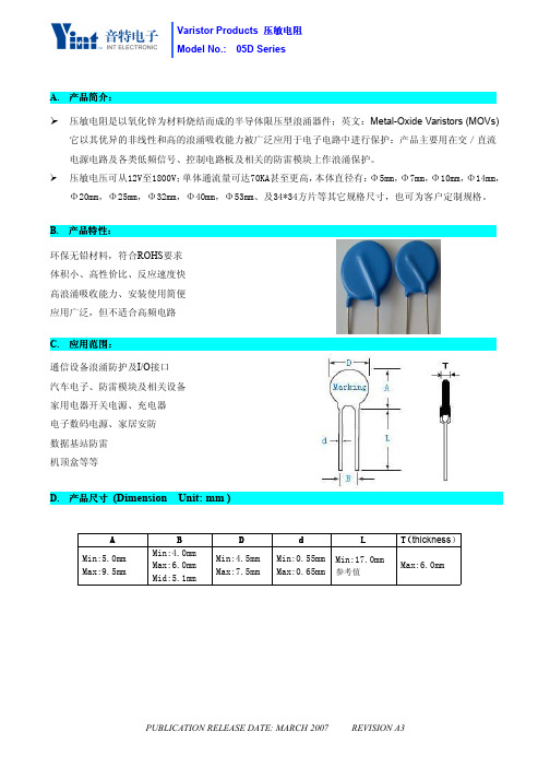
各规格静态功率见说明书。
电容量
使用 1KHZ ,电平<=1Vrms 的电信号,测量压敏电阻的电容量。 电容量小于规定的额定值,
测试设备:CY2646A 型号容量测试仪
各规格电容量见规格书。
标准测试条件:温度 15℃-35℃,相对湿度 45%-75%,气压 86k pa~106 k pa。
PUBLICATION RELEASE DATE: MARCH 2007 REVISION A3
测试设备:脉冲发生器 记忆示波器
MYZ-3 型压敏电阻三参数测试仪
施加本说明书规定的最大 冲击能量:压敏电阻无外观 损伤;压敏电压变化率≤± 10%。
通流容量
电压温度 系数
施加给压敏电阻波形为 8/20µS 的脉冲电流,时间间隔 2 分钟, 同方向施加两次,使压敏电压变化率在±10%以内的最大电流峰 施加本说明书规定的最大
300
385
810
400
200
05D511K 510(459~561)
320
410
845
400
200
05D561K 560(504~616)
350
455
920
400
200
05D621K 620(558-682)
385
505
1025
800
600
05D681K 680(612-748)
385
560
1125
2ms 0.3
0.5
0.4
0.6
0.5
0.8
0.6
0.9
0.8
1.1
1.0
1.3
1.0
1.6
1.2
2.5
- 1、下载文档前请自行甄别文档内容的完整性,平台不提供额外的编辑、内容补充、找答案等附加服务。
- 2、"仅部分预览"的文档,不可在线预览部分如存在完整性等问题,可反馈申请退款(可完整预览的文档不适用该条件!)。
- 3、如文档侵犯您的权益,请联系客服反馈,我们会尽快为您处理(人工客服工作时间:9:00-18:30)。
FEATURESPRESSURE SENSOR CHARACTERISTICSPart NumberSCC05(D,G)SCC15A SCC15(D,G)SCC30(A,D,G)SCC100A SCC100(D,G)9SCC300APerformance Characteristics (Individual Models) I S = 1.0 mA, T A = 25°C 1Operating Pressure Range0-5 psid(g)0-15 psia 0-15 psid(g)0-30 psid(g)0-100 psia 0-100 psig 0-300 psiaMaximum Over Pressure20 psi 30 psia 30 psi 60 psi 150 psia 150 psig 450 psiaAccuracy 20.50%0.50%0.50%0.50%0.50%0.50%0.50%Effect On Span 3(0°C-50°C)1.50%1.50%1.50%1.50%1.50%1.50%1.50%Effect On Offset 4(0°C-50°C)2.00%2.00%2.00%2.00%2.00%2.00%2.00%Full-Scale Span 5(mV)25-6530-9540-9560-15085-22585-22550-120Performance Characteristics (All Models) I S = 1.0 mA, T A = 25°CCharacteristicsZero Pressure OffsetCombined, Linearity, Hysteresis, Repeatability 2Temperature Effect on Span 3, 8Temperature Effect on Offset 4,8Long T erm Stability of Offset and Span 6Response Time (10% to 90%)7Input Impedance Output ImpedanceMin.-30.0---------------4.004.00Typ.-100.250.250.500.100.105.005.00Max.20.00.501.502.00------6.506.50UnitmV %FSO %FSO %FSO %FSO mSec k Ωk ΩSpecification Notes:1:Reference Conditions: Supply Current = 1.0 mA, T A =25°C, Common-mode Line Pressure = 0 psig, Pressure Applied to P1, unless otherwise noted.2:Accuracy is the sum of Hysterisis and Linearity. Hysterisis is the maximum output difference at any point within the operating pressure range for increasing and decreasing pressure.Linearity refers to the best straight line fit as measured for the offset, full-scale and 1/2 full-scale pressure at 25°C.3:This is the maximum temperature shift for span when measured between 0°C and 50°C relative to the 25°C reading. Typical temperature coefficients for span and resistance are -2200 ppm/°C and +2200 ppm/°C respectively.4:This is the maximum temperature shift for offset when measured between 0°C and 50°C relative to the 25°C reading.5:Span is the algebraic difference between the output voltage at full-scale pressure and the output at zero pressure.6:Maximum difference in output at any pressure with the operating pressure range and temperature within 0°C to 50°C after:a)100 temperature cycles, 0°C to 50°C b) 1.0 million pressure cycles, 0 psi to full-scale span7:Response time for a 0 psi to full-scale span pressure step change. 10% to 90% rise time8:Temp effect on span and offset are guaranteed by design. Therefore these parameters are not 100% tested.9:The SCC100D devices can only be used in a forward gauge mode. Application of more than 30 psig to the back side of any of the SCC Series devices can result in device failure.Maximum Ratings (For All Devices)Supply Current, I S1.5 mATemperature RangesCompensated 0°C to +50°C Operating -40°C to +85°C Storage-55°C to +125°C Humidity0 to 100 %RHLead T emperature (soldering 4 sec)250°C Common-Mode Pressure150 psiPHYSICAL DIMENSIONSButton PackageBasic Sensor DIP "D2" PackagePHYSICAL DIMENSIONS (cont.)Basic Sensor DIP "D4" PackageN PackagePressure RangeAbsolute Pressure0 - 15 psi 0 - 30 psi0 - 100 psi 0 - 300 psiGage Pressure0 - 5 psi 0 - 15 psi 0 - 30 psi 0 - 100 psiDifferential Pressure0 - 5 psi 0 - 15 psi 0 - 30 psi 0 - 100 psi (9)Order Part NumberButton PackageSCC15A SCC30A SCC100A---use differential devices SCC05D SCC15D SCC30D SCC100D"N" Package SCC15AN SCC30AN SCC100AN---use differential devices SCC05DN SCC15DN SCC30DN SCC100DNTO Package SCC15AHO SCC30AHO SCC100AHO SCC300AHO SCC05GSO SCC15GSO SCC30GSO---------------DIP Packagesingle portSCC15AD2SCC30AD2SCC100AD2SCC05GD2SCC15GD2SCC30GD2---------------DIP Package Dual port------------------------SCC05DD4SCC15DD4SCC30DD4SCC100DD4SenSym and Sensortechnics reserve the right to make changes to any products herein. SenSym and Sensortechnics do not assume any liability arising out of the application or use of any product or circuit described herein, neither does it convey any license under its patent rights nor the rights of others.ORDERING INFORMATIONPHYSICAL DIMENSIONS (cont.)AHO Package (TO-5)GSO Package (TO-39)。