3033C
大金变频空调FTXN325LC内机开关电源原理与检修
w w w .j w l 989.c nAPPL -I A /S I C E T R E I P A I T R I N G大金变鳎空调FTXN325L C 内W f 关电源原理与检修□邹敏红张湘粵大金变频空调在业界一直有比较好的口碑, 本文给大家介绍一款型号是FTXN 325L C 的三级 能效变频空调,室内风机使用P G 电机,外风机使 用交流风机,由于未使用直流风机所以能效不太 高,用料与一级能效的相比还是有一定的区别。
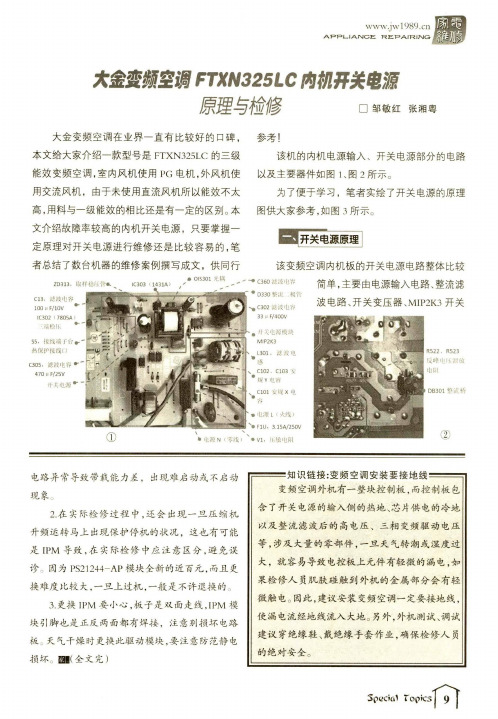
本 文介绍故障率较高的内机开关电源,只要掌握一 定原理对开关电源进行维修还是比较容易的,笔 者总结了数台机器的维修案例撰写成文,供同行参考!该机的内机电源输入、开关电源部分的电路 以及主要器件如图1、图2所不。
为了便于学习,笔者实绘了开关电源的原理 图供大家参考,如图3所示。
该变频空调内机板的开关电源电路整体比较简单,主要由电源输入电路、整流滤波电路、开关变压器、MIP 2K 3开关>电源N (芩线)Z D 313.取样稳瓜管氣_I C 303 ' 1431A )• O I S 301 光耦C 13,滤波电辑 100 M F /10V *I C B 02 (7805A )端稳川.•55,接线端子台•热保护接线口C 305,漶波电容• 470 M F /25V 什关电源>► C 360滤波电WD 330幣流::极管C 302滤波屯荇33 P F /400V开々电源模垅M I P 2K 3L 301.滤波电C 102、 C 103 女规Y 电容 C 101安规X 电容电濂L (火线)F 1U . 3.15A /250V• V I , I 丨丨敏电阻R 522、 R 523反峰电甩泄放电附D B 301整流桥电路异常导致带载能力差,出现难启动或不启动 现象2.在实际检修过程中,还会出现一旦压缩机升频运转马上出现保护停机的状况,这也有可能是IPM 导致,在实际检修中应注意区分,避免误诊因为P S 21244-A P 模块全新的近百元,而且更换难度比较大,一旦上过机,一般是不许退换的:)3. 更换丨P M 要小心,板子是双面走线J P M 模块引脚也是正反两面都有焊接,注意别损坏电路板天气干燥时更换此驱动模块,要注意防范静电损坏:■丨(全文完)知识链接:变频空调安装要接地线变频空调外机有一整块控制板,而控制板包含了开关电源的输入侧的热地、芯片供电的冷地以及整流滤波后的高电压、三相变频驱动电压等,涉及大量的零部件,一旦天气转潮或湿度过大,就容易导致电控板上元件有轻微的漏电,如果检修人员肌肤碰触到外机的金属部分会有轻微触电。
TT-3033手枪兴衰史

TT-30/33手枪兴衰史20世纪初期,由于缺乏现代工业基础,俄军及早期的苏军所使用的武器装备基本都需要进口。
在苏共夺取全国政权后,决策层决定实现军用装备的国产化,并为之投入巨大精力。
美制M1911手枪的苏联克隆版——托卡列夫TT-30/33系列手枪,就出产于这一时期……托卡列夫小传托卡列夫于1871年出生在一个哥萨克家庭,其幼年在罗斯托夫的哥萨克驻军军营中度过。
他几乎未接受过正规的学校教育,但从小就对机械和技术非常着迷。
1885年,托卡列夫接受了当地驻军司令部开办的职业教育,并作为学徒进入锻工车间实习。
一年后,他就在机械方面展现出惊人的天赋,于是被送到新切尔卡斯克军事技术学校深造。
托卡列夫不负众望顺利通过了考试,学习枪械制造。
毕业后被分配至第12哥萨克骑兵团,成为一名枪械修理兵;不久后,又作为预提干军官学员参加了准尉军官军校的学习。
1907年,新任一级准尉的托卡列夫来到俄轻武器设计师向往的殿堂——位于列宁格勒奥拉宁巴姆的军官射击学校学习。
在那里,他接触到了当时最先进的自动枪械,并以此为起点开始了轻武器的设计。
1908年,托卡列夫的第一件作品设计完成。
1913年,他进入谢斯特罗列茨克兵工厂监制枪械。
然而,第一次世界大战的爆发彻底改变了他按部就班的生活,期间他作为军械军官直接参战,直到1916年才又回到谢斯特罗列茨克兵工厂。
一战后,苏维埃革命胜利,托卡列夫和他后来的良师益友费德洛夫一起于 1920年进入图拉的TsKB-14设计局,从事枪械的相关工作。
在这之后的20多年里,托卡列夫共设计出自动/半自动步枪、卡宾枪、冲锋枪、手枪等总计达27 款枪械。
1944年,为表彰他对红军武器设计的功勋,苏联政府为他颁发了二等苏沃洛夫勋章;此外,他还获得一次社会主义劳动英雄称号、四次列宁勋章、两次红旗勋章和斯大林奖金。
1968年,托卡列夫在家中病逝,享年97岁。
TT-30前身——M1930艰难出世1928年,炮兵工业委员会为苏联红军挑选各类枪械时,托卡列夫也带着自己设计的轻机枪参与了竞选。
岛津LC-2030C高效液相色谱仪操作指南
岛津高效液相色谱仪
Prominence-i LC-2030 LC-2030C LC-2030C 3D
操作指南
请仔细阅读本说明书,正确使用本产品。 请妥善保管本说明书以备随时查阅。
本说明书是日文版《岛津高效液相色谱仪Prominence-i LC-2030 LC-2030C LC-2030C 3D操作 指南》(228-91534)(第1版 2014年2月)的译文。
ã 2014 Shimadzu Corporation. All rights reserved.
Prominence-i LC-2030 LC-2030C LC-2030C 3D
228-91536A
Hale Waihona Puke 前言请在使用本产品前仔细阅读本说明书。
非常感谢您购买本公司产品。
本说明书记载了本产品操作窗口的操作及Web窗口、iPhone或iPad中的操作方法。请仔细阅读 本说明书,并正确使用本产品。此外,本产品以手册或PDF文档的形式附带以下说明书。PDF 文档收录在说明书CD-ROM(P/N S228-56248-41)内。
此时,如果周围存在一定浓度的易燃气体,将因释放的热能而 起火。
使用说明书的标记
使用说明书的标记
本说明书将危险和损害程度分为:
标记
说明
具有潜在危险,操作不当可能导致人员死亡或重伤。
具有潜在危险,操作不当可能导致人身轻微或中度伤害以及设备损 坏。
确保正确使用本产品的附加说明。
本说明书标记含义如下: 标记 表示严禁操作内容。
IC datasheet pdf-REF3012,REF3020,REF3025,REF3033,REF3040,REF3030,pdf(50ppm_°C Max, 50μA in SOT23-3

VOLTAGE (V) 1.25 2.048 2.5 3.0 3.3 4.096
DROPOUT VOLTAGE vs LOAD CURRENT 350
IN 1 REF3012 REF3020 REF3025 REF3030 REF3033 REF3040 SOT23-3
300
Dropout Voltage (mV)
REF3012 REF3020 REF3025 REF3030 REF3033 REF3040
SBVS032F – MARCH 2002 – REVISED AUGUST 2008
50ppm/°C Max, 50µA in SOT23-3 CMOS VOLTAGE REFERENCE
"
R30F
"
REF3033
"
SOT23-3
"
DBZ
"
–40°C to +125°C
"
R30D
"
REF3040
"
SOT23-3
"
DBZ
"
–40°C to +125°C
"
R30E
"
"
"
"
"
NOTE: (1) For the most current package and ordering information, see the Package Option Addendum at the end of this document, or see the TI website at .
ELECTRICAL CHARACTERISTICS
屹晶微电子EG3033芯片数据手册说明书

版本变更记录版本号日期描述V1.0 2021年11月12日EG3033数据手册初稿V1.1 2022年3月10日EG3033数据手册V1.1目录1. 特性 (1)2. 描述 (1)3. 应用领域 (1)4. 引脚 (2)4.1 引脚定义 (2)4.2 引脚描述 (2)5. 结构框图 (4)6. 典型应用电路 (5)7. 电气特性 (5)7.1 极限参数 (5)7.2 典型参数 (6)7.3 开关时间特性及死区时间波形图 (7)8. 应用设计 (8)8.1 VCC端电源电压 (8)8.2 输入逻辑信号要求和输出驱动器特性 (8)9. 封装尺寸 (10)9.1 SOP16封装尺寸 (10)EG3033芯片数据手册V1.11. 特性⏹三相P/N MOS管栅极驱动⏹电源电压输入范围:6V-36V⏹适应3V-30V输入电压⏹具有VCC欠压保护⏹内置5V/50mA输出LDO⏹内建死区控制电路⏹自带闭锁功能⏹LIN1/2/3输入通道高电平有效,控制LO输出⏹HIN1/2/3输入通道高电平有效,控制HO输出⏹封装形式:SOP162. 描述EG3033是一款高性价比三相PMOS、NMOS管栅极驱动专用芯片,内部集成了LDO、死区时控制电路、欠压关断电路、闭锁电路、输出驱动电路,用于电机控制器、电源的驱动电路。
EG3033 的电源电压范围6V~36V,静态功耗小于1mA。
该芯片集成5V输出LDO,可为外部MCU 等器件供电。
当输入电压超过12V时,为了更好的匹配P/N MOS管,LO输出最高电压为11V,HO输出最低电压为VCC减去11V。
LO输出电流能力I O+/- 0.045/0.28A,HO输出电流能力I O+/- 0.26/0.04A。
3. 应用领域⏹吸尘器⏹风扇⏹变频水泵控制器⏹电源⏹电机驱动器⏹筋膜枪4. 引脚引脚定义4.14.2 引脚描述5. 结构框图5VGNDLO1HO2LO2HO1LO1图5-1. EG3033内部电路图6. 典型应用电路图6-1. EG3033典型应用电路图7. 电气特性7.1 极限参数无另外说明,在T A=25℃条件下注:超出所列的极限参数可能导致芯片内部永久性损坏,在极限的条件长时间运行会影响芯片的可靠性。
SI-3033C资料

s Features•Compact full-mold package (equivalent to TO220)•Output current: 1.5A•Low dropout voltage: V DIF ≤1V (at I O =1.5A)•Variable output voltage (rise only)May be used for remote sensing•Output ON/OFF control terminal is compatible with LS-TTL. (It may be directly driven by LS-TTL or standard CMOS logic.)•Built-in foldback overcurrent (SI-3033C: Drooping type overcurrent), ov-ervoltage, thermal protection circuitss Applications•For stabilization of the secondary stage of switching power supplies •Electronic equipments Absolute Maximum Ratingss Electrical Characteristics*1:"A" may be indicated to the right of the Sanken logo.*2:V IN(max) and I O(max) are restricted by the relation P D(max)=(V IN -V O )•I O =18(W).*3:Refer to the dropout voltage.(Refer to Setting DC Input Voltage on page 7.)*4:I S 1 is specified at –5(%) drop point of output voltage V O on the condition that V IN =V O +3V , I O =0.5A.*5:Output is ON even when output control terminal V C is open. Each input level is equivalent to LS-TTL. Therefore, it may be directly driven by anLS-TTL circuit.*6:A foldback type overcurrent protection circuit is built into the I C regulator (excluding SI-3033C). Therefore, avoid using it for the following applica-tions as it may cause starting errors:(1) Constant current load (2) Plus/minus power (3) Series power (4) V O adjustment by raising ground voltage(T a =25°C unless otherwise specified)s Electrical Characteristicsa Array *1:"A" may be indicated to the right of the Sanken logo.*2:V IN(max) and I O(max) are restricted by the relation P D(max)=(V IN-V O)•I O=18(W).*3:Refer to the dropout voltage.(Refer to Setting DC Input Voltage on page 7.)*4: I S1 is specified at –5(%) drop point of output voltage V O on the condition that V IN=V O+3V, I O=0.5A.*5:Output is ON even when output control terminal V C is open. Each input level is equivalent to LS-TTL. Therefore, it may be directly driven by an LS-TTL circuit.*6:A foldback type overcurrent protection circuit is built into the I C regulator (excluding SI-3033C). Therefore, avoid using it for the following applica-tions as it may cause starting errors:(1) Constant current load (2) Plus/minus power (3) Series power (4) V O adjustment by raising ground voltages Block Diagrams Standard External Circuits T a-P D Characteristics1. Variable output voltage with a single external resistorThe output voltage may be increased by inserting resistor R EX between terminals No.4 (sensing terminal) and No.3 (output terminal). The cur-rent I REX flowing into terminal No.4 is 1mA (typ.)(SI-3033C:0.43mA (typ.)),therefore the adjusted output voltage V OUT is:V O =V 04+I REX •R EX *V 04: output voltage of SI-3000C seriesHowever, the built-in resistor (between terminals No. 4 and No.1) is a semiconductor resistor, which has approximately thermal characteris-tics of +0.2%/°C.It is important to keep the thermal characteristics in mind when adjust-ing the output voltage.2. Variable output voltage with two external resistorsThe output voltage may be increased by inserting resistors R EX1 be-tween terminals No.4 (sensing terminal) and No.3 (output terminal) and R EX2 between terminals No.4 and No.1 (ground terminal).The current I 4IN flowing into terminal No.4 is 1mA (typ.)(SI-3033C:0.43mA(typ.)) so the thermal characteristics may be improved compared to the method shown in 1 by setting the external current I REX1 at ap-proximately 5 times the value of I 4IN (stability coefficient S=5).The adjusted output voltage V OUT in this case is:V O =V 04+R EX1•I REX1I REX1=S•I 4INThe value of the external resistors may be obtained as follows:R EX1= V O -V 04 R EX2=V 04S•I 4IN , (S-1)•I 4IN*V 04: Output voltage of SI-3000C seriesS: Stability coefficient of I 4IN (may be set to any value)Note: In the SI-3000C series, the output voltage increase can be ad-justed as mentioned above. However, when the rise is set to ap-proximately 10V compared to output voltage V 04, the necessaryoutput current may not be obtained due to the S.O.A. protectioncircuit in the SI-3000C series.5O u t p u t V o l t a g e V O (V )External Resistor R EX (k Ω)External Resistor R EX1 (k Ω)O u t p u t V o l t a g e V O (V )External Variable Output Voltage Circuits Typical Characteristics。
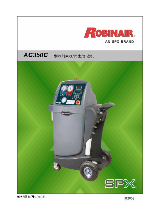
AC350C服务手册V1.0
面板控制阀总成 ...................................................................... 22
的或雾状的制冷剂和润滑剂可请不要吸入挥发剂的或雾状的制冷剂和润滑剂暴露在挥发或雾状的制冷剂和润滑剂中能导致个人的伤害特别是眼睛鼻子喉咙和肺
AC350C 制冷剂回收/再生/加注机
制冷剂回收/再生/充注机
-1-
安全警告
安全定义:请遵循使用手册中重要的“警告”、“注意”、“重要提示”和“提示”信息;这些信息定义 如下:“警告”提示您可能冒着严重的导致个人受伤,甚至死亡的危险;“注意”提示您可能冒着个人受 伤、财产损失或设备严重损害的危险;“重要提示”提示您可能冒着设备损害的危险;“提示”为您提供 清楚和有用的提示。安全信息包括斯必克(SPX)公司意识到的一些情形;但斯必克(SPX)公司不能够提 示您所有可能的危险。您必须确定所有的情形和程序不能危害到您的个人安全。
主控制板 ............................................................................ 23
继电器控制板 ........................................................................ 24
使用装有R-134a或R-12制冷剂的设备 本设备是为对制冷剂R-134a或R-12进行回收、再 生、充注而设计的。使用者必须确定此设备只用于一种制冷剂。不要尝试将此设备用于另 外一种制冷剂。不要通过一个系统或在一个容器内混合不同种类的制冷剂;混合制冷剂将 对设备和车辆空调系统带来严重的损害。如因不当使用所造成任何后果,由用户负责。 设备内部的高电压有被电击的危险 被电击可能导致人身伤害。在打开设备后背门或维修 设备之前,务必断开电源。
SI-3033KS资料

s Features•Compact surface-mount package (SOP-8)•Output current: 1.0 A•Low-ESR capacitor can be used.•Low current consumption Iq ≤ 350 µA (I O = 0 A, V C = 2 V)•Low current consumption Iq (OFF) ≤ 1 µA (V C = 0 V)•Low dropout voltage V DIF ≤ 0.6 V (I O = 1 A)• 4 types of output voltages (1.8 V , 2.5 V, 3.3 V , and variable type) available •Output ON/OFF control pin compatible with LS-TTL•Built-in dropping type overcurrent, thermal protection circuitss Applications•Local power supplies•Battery-driven electronic equipmentsAbsolute Maximum Ratings(T a =25°C)*1:V IN (max) and I O (max) are restricted by the relationship PD = (V IN - V O ) x I O . Calculate these values referring to thepower dissipation vs. copper area data shown in this document.*2:When mounted on a glass epoxy board measuring 1600 mm 2 (with 2% copper area).s Electrical Characteristics*1:Refer to the description on the dropout voltage.*2:The I s1 is specified as the 5% drop point of output voltage V O on the condition that V IN = V O + 1 V, and I O = 10 mA.*3:Output is OFF when the output control pin (V C pin) is open. Each input level is equivalent to that for LS-TTL. Therefore, the device can be driven directly by an LS-TTL circuit.s External Dimensions(Unit : mm)s Block Diagrams Example of Solder Pattern DesignsTaping Specificationss Typical Characteristics Examples of SI-3012KS and SI-3025KS(T a =25°C) *V out =2.5 V for SI-3012KS (RS=24 k Ω)Dropout voltageRise characteristicsLine regulationLoad regulationOvercurrent protection characteristicsInput voltage vs. Quiescent currentCircuit currentControl terminal voltage vs. Output voltageControl terminal voltage vs. Control terminal current10.80.60.40.200.20.4Output current A0.60.81D r o p o u t v o l t a g eVInput voltage VO u t p u t v o l t a g e VInput voltage VO u t p u t v o l t a g e VOutput current AO u t p u t v o l t a g e VOutput current AO u t p u t v o l t a g e VInput voltage VQ u i e s c e n t C u r r e n t AµInput voltage VG N D c u r r e n t mAControl ternimal voltage VO u t p u t v o l t a g e V3020251551001234Control terminal voltage VC o n t r o l t e r m i n a l c u r r e n t Aµs Typical Characteristics Examples of SI-3033KS(T a =25°C)Dropout voltageRise characteristicsLine regulationLoad regulationOvercurrent protection characteristicsInput voltage vs. Quiescent currentCircuit currentControl terminal voltage vs. Output voltageControl terminal voltage vs. Control terminal current10.80.60.40.200.20.4Output current A0.60.81D r o p o u t v o l t a g e VInput voltage VO u t p u t v o l t a g e VInput voltage VO u t p u t v o l t a g e VOutput current AO u t p u t v o l t a g e VOutput current AO u t p u t v o l t a g e VQ u i e s c e n t C u r r e n tAInput voltage VµInput voltage VG N D c u r r e n t mAControl terminal voltage VO u t p u t v o l t a g e V3020251551001234Control terminal voltage VC o n t r o l t e r m i n a l c u r r e n t Aµ。