Backup of X4-20
WPI接口定义_V1.5

第2页
远景能源变频器设计文档 V1.4
2013 年 6 月 ................................................................................................................................................................................ 3 2 硬件电路接口示意图 ......................................................................................................................................................... 4 3 WPI_RELAY(继电器板)接口定义 ............................................................................................................................. 5
1.4
6/4/2013
Page-paragraph All 2 2 2、5、6 3.1、3.4
3.1 3.4,4.2
4.2 3.1,3.4
附录 4.2,7.3 3.1 4.6
X20系统用户手册说明书
网络信息安全管理员1

数学密码:基于数学上NP问题 其他密码:基于物理定理——测不准原理,等
按安全程度:计算安全,绝对安全
二、基本概念(6)
6、密码学科分类
密码学
信息隐藏技术
密码编码学
密码分析学
数字水印 阈下信道 化学隐写术 物理隐写术等
分组密码学
序列密码学
私钥密码
古典密码 DES IDEA AES等
二、基本概念(5)
5、密码体制分类:
按密钥个数:对称(私钥,单钥)体制,公钥(非对称,双钥)体制;
对称密码体制:加密密钥与解密密钥相同或可以在有效时间内相互推导。 公钥密码体制:加密密钥与解密密钥不同或不可以在有效时间内相互推导。
按分组长度:分组密码体制,序列密码体制。 分组密码体制:明、密文分组长度及密钥长度有限且固定 序列密码体制:明、密文不分组,密钥长度无限
4、f 函数:
f ( Ri-1 , ki ) = P( E ( Ri-1 ) ki
Ri-1
E
48比特
ki 48比特
S1
S2
S3
S4
S5
S6
S7
S8
32比特
P
32比特
s1 三、对称密码体制(5)
5、S盒:
Si(h1h2h3h4h5h6)=Tablei(h1h6,h2h3h4h5)
S1
0
1
2
3
0
14
二、计算机网络面临的威胁
安全威胁=恶意攻击+使用失误+设计缺陷+代码错误 恶意攻击:主动攻击,被动攻击 使用失误:安全意识,技术水平,简短密码 设计缺陷:匿名帐户,恶意后门等 代码错误:缓冲区溢出等动态错误
MA说明书
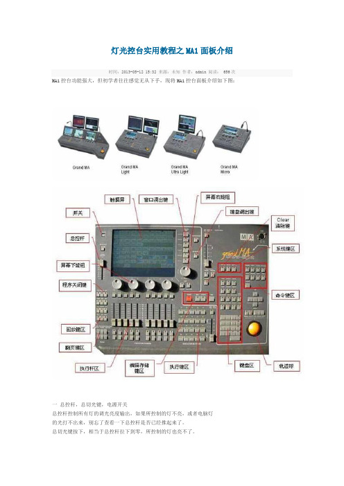
灯光控台实用教程之MA1面板介绍时间:2013-05-12 15:32 来源:未知作者:admin 阅读: 656次MA1控台功能强大,但初学者往往感觉无从下手,现将MA1控台面板介绍如下图:一总控杆,总切光键,电源开关总控杆控制所有灯的调光亮度输出,如果所控制的灯不亮,或者电脑灯的光打不出来,别忘了查看一下总控杆是否已经推起来了。
总切光键按下,相当于总控杆拉下到零,所控制的灯也亮不了。
电源开关在左上角,按下,控制台会开始启动,如果已经在开机状态,那么,再按下,就会关机,关机时会自动保存所有的程序和设定。
提示:总切光键默认为点控状态,即按下时切光,一松开,就不起作用,象点控键一样。
这是可以通过改变默认值而改变它的状态的。
二、屏幕显示区触摸屏,显示的内容由操作者采用窗口组成元素进行自由组合设定。
触摸屏既是信息显示的窗口,也是直接进行触摸操作的界面。
窗口调出键,6个,可以存储和调出编好的窗口。
键盘调出键,当需要用到键盘输入数值和字母时,按此键,在屏幕上出现一个软键盘,供输入使用。
幕右旋钮,主要用于滚动翻阅屏幕信息,正常旋转旋钮,光标上下移动。
按下旋钮并旋转,光标位置左右移动。
屏幕下旋钮,4个,用于调节设定数值,在不同的界面状态下,输入的数值含义不同。
可以用它们调节灯具的亮度,颜色,图案,位置等参数。
正常旋转选钮为微调,按下并旋转为快速粗调。
灯光控台实用教程之MA1面板介绍(2)时间:2013-05-12 15:32 来源:未知作者:admin 阅读: 657次三执行键区程序执行键,5只X4排,共20只(最大的型号是40只)。
可以翻64页。
用于存储和调用程序。
执行键时间杆,在执行键右侧,用于设定执行键之间的切换时间。
四执行杆区程序执行杆,10只(最大的型号是20只),可以翻64页。
用于存储和调用程序,编组,效果等。
每个执行杆上有一个按键,下有2个按键,它们的功能可以根据需要设定。
单控杆,如果你的控制台需要控制硅箱进行调光,那么,执行杆可以被切换成为单控杆。
戴尔 DR4000 磁盘备份设备上设置 Veeam说明书
Setting up Veeam on theDell™ DR4000 Disk Backup ApplianceA Dell Technical White Paper© 2012 Dell Inc. All Rights Reserved. Dell and the Dell logo, and other Dell names and marks are trademarks of Dell Inc. in the US and worldwide. Veeam is a trademark of Veeam.Table of contentsExecutive Summary (4)1Install and Configure the DR4000 (5)2Configure the Backup Server (12)3Set up Veeam (14)4Set up the DR4000 Cleaner (19)5Monitoring Dedupe, Compression & Performance (20)Executive SummaryThis paper provides information about how to set up the Dell DR4000 as a backup to disk target forVeeam® Backup & Replication™ software. This paper is a quick reference guide and does not include allDR4000 deployment best practices.See the DR4000 documentation other data management application best practices whitepapers foradditional information.1Install and Configure the DR40001.Rack and cable the DR4000 appliance, and power it on.2.Log into iDRAC using the default address 192.168.0.1, user name root, and the password calvin.unch the virtual console.4.Once the virtual console is open, log in to the system as user administrator and the passwordSt0r@ge! (The “0” in the password is the numeral zero.).5.Set the user-defined networking preferences.6.View the summary of preferences and confirm that it is correct.7.Log into the DR4000 administrator console, using the IP address you just provided for theDR4000, user administrator and the password St0r@ge! (The “0” in the password is the numeral zero.).8.Join the DR4000 to Active Directory.a.Select Active Directory in the tree on the left hand side of the dashboard.b.Enter your Active Directory credentials.9.Create and mount the container.a.Select Containers in the tree on the left side of the dashboard, and then click the Create linkat the top of the page.b.Enter a Container Name and select the Enable CIFS check box.c.Select the client access credentials preferred.For improved security, Dell recommends adding IP addresses for the following (Not all environments will have all components):-Backup console (Veeam Server)-Hyper-V hosts (on-host proxy for Hyper-V environments)s -Off-host proxies (for Hyper-V environments)-Backup proxies (for vSphere environments)d.Click Create a New Container.e.Confirm that the container was added.f.Click Edit, and write down the container path, which you will use later to target the DR4000.g.Click Cancel to exit.2Configure the Backup Server1.Log into the media server and click on Start My Computer.2.Click Map network drive.3.For Folder, enter the path to the container on the DR4000.4.Select the Reconnect at logon check box.5.When prompted, enter the DR4000 login credentials.The DR4000 container is now mounted to your backup server.3Set up Veeam1.Open the Veeam Backup & Replication console.2.Click the Backup Infrastructure section, right-click on Backup Repositories, and select AddBackup Repository.3.Enter a name that is self-documenting, such as “CIFS-DR4000-Deduplication,” to indicate thedevice, protocol and feature of the repository.4.Select Shared folder.5.For Shared folder, enter in the name of the DR4000 (or TCP/IP address used above) and the sharename, and then click Next.6.Configure the repository wizard to note that the DR4000 is a deduplication target. Click theadvanced button and select the additional option for “Aligning backup file data blocks” (fixedlength write). Optionally select the decompress value. The decompress option will make theDR4000 do all of the compression.All other options for the new repository wizard are independent of anything related to theDR4000.7.Create a new backup job in the Veeam Backup console, for either Hyper-V or vSphere; the optionsspecific to the DR4000 are the same.8.Select one or more virtual machines, folders, datastores, resource pools, vApps, SCVMM clusters,etc. for the backup.9.Ensure that the repository for this job is the DR4000.10.On the storage wizard of the backup job, click the Advanced button to check a number ofimportant settings.11.Ensure the backup job is running in Incremental mode, and avoid the rollback transformationoption. This is a default for new jobs.12.Change the compression engine to Dedupe-friendly in the storage tab of the advanced settings.The deduplication option to local target will perform deduplication by Veeam at 1 MB, landing on the DR4000 for additional deduplication and compression.All other options are independent of the backup target.4Set up the DR4000 CleanerOnce all the backup jobs are setup the DR4000 cleaner must be scheduled. The DR4000 cleaner shouldrun at least 6 hours per week when backups are not taking place, generally after a backup job hascompleted.Performing scheduled disk space reclamation operations are recommended as a method for recoveringdisk space from system containers in which files were deleted as a result of deduplication.5Monitoring Dedupe, Compression & Performance After backup jobs have run the DR4000 will track Capacity, Storage Savings and Throughput on theDR4000 dashboard. This information is valuable in understanding the benefits the DR4000.21 Setting up Veeam on the Dell™ DR4000 Disk Backup Appliance。
veritas backup exec20 使用手册
veritas backup exec20 使用手册Veritas Backup Exec 20 使用手册一、简介Veritas Backup Exec 20 是一款功能强大的数据备份和恢复软件。
它能够帮助用户轻松地备份和恢复各种类型的数据,包括文件、文件夹、数据库和虚拟机。
本手册将详细介绍如何正确安装、配置和使用Veritas Backup Exec 20,以及一些常见问题的解决方法。
二、安装与配置1. 安装步骤步骤1:双击安装程序,开始安装向导。
步骤2:选择安装类型,例如完整安装或自定义安装。
步骤3:选择安装位置,建议将程序安装在系统盘。
步骤4:等待安装完成,并根据提示进行进一步配置。
2. 配置备份设备步骤1:打开Veritas Backup Exec 20控制台。
步骤2:选择“配置和设置”选项。
步骤3:选择“备份设备”选项卡。
步骤4:点击“添加”按钮,选择要添加的备份设备,并按照提示完成配置。
三、备份与恢复1. 创建备份任务步骤1:打开Veritas Backup Exec 20控制台。
步骤2:选择“备份和还原”选项。
步骤3:选择“备份任务”选项卡。
步骤4:点击“新建备份任务”按钮,并按照提示完成配置。
2. 恢复数据步骤1:打开Veritas Backup Exec 20控制台。
步骤2:选择“备份和还原”选项。
步骤3:选择“恢复任务”选项卡。
步骤4:点击“新建恢复任务”按钮,并按照提示完成配置。
四、常见问题解决1. 备份任务失败问题描述:备份任务运行时失败,无法完成备份。
解决方法:检查备份设备是否正常工作,并确保备份目标的访问权限正确设置。
2. 恢复任务失败问题描述:恢复任务运行时失败,无法成功恢复数据。
解决方法:检查恢复目标是否可用,并确保恢复参数正确配置。
3. 备份效率低问题描述:备份任务执行效率较低,备份速度慢。
解决方法:优化备份策略,检查网络连接是否稳定,并确保备份设备性能满足要求。
ServeRAID M5014 ServeRAID M5015 SAS SATA 控制器快速安装指南

®Thank you for purchasing the ServeRAID M5014® orServeRAID M5015 SAS/SATA controller. Please take a few minutes to read this Quick Install Guide before you install your controller. For more information about any topiccovered in this guide, refer to the other documents on your ServeRAID-M Support CD.The ServeRAID M5014 and ServeRAID M5015 SAS/SATA (Serial Attached SCSI/Serial ATA II) controllers are PCI-Express 2.0, low-profile RAID controllers based on theSAS2108ROC, which is a SAS/SATA RAID-On-Chip device. They control eight internal 6 Gb/s SAS/SATA ports through two SFF-8087 Mini SAS 4i internal connectors.Note:Record your controller serial number in a safe location in case you need to contact IBM.The ServeRAID M5000 Series Battery Assembly can be mounted directly to the controller using a daughtercard.For more information about this controller and the battery assembly, refer to the ServeRAID M5015 SAS/SATAController User’s Guide on the ServeRAID-M Support CD.Note:SATA II is the only type of SATA supported by this RAID controller.S e r v e R A I D C O N T R O L L E R I N S T A L L A T I O NPerform the following steps to install your ServeRAID M5014 or ServeRAID M5015 SAS/SATA controller.Step 1Unpack the ControllerUnpack the controller in a static-freeenvironment. Remove the controller from the antistatic bag and inspect it for damage. If the controller appears to be damaged, or if the ServeRAID-M Support CD is missing, contact your place of purchase.The CD contains the following documents:•ServeRAID M5014/M5015 SAS/SATA Controllers User’s Guide•ServeRAID-M Software User’s Guide•ServeRAID-M Device Driver Installation User’s GuideStep 2Prepare the ComputerReview all safety information provided with the computer. Unplug the power cords from the power supplies, disconnect the computer from the network, and remove the computer cover. See the documentation provided with the computer for instructions.Step 3Review the ConnectorsFigure 1 shows the location of the connectors.Figure 1ServeRAID M5014/M5015 Card LayoutAttention:Back up your data before you change yoursystem configuration. Otherwise, you might lose data.Important:When you handle static-sensitive devices, takeprecautions to avoid damage from static.Attention:Before you install the controller, make sure thatthe computer is disconnected from the power and from any networks.ServeRAID M5014/M5015 SAS/SATA ControllersQuick Install GuideTable1 describes the connectors on theServeRAID M5014 controller and the ServeRAIDM5015 controller.Table1Jumpers and ConnectorsNote:JT1, JT2, and JT4 are behind the ServeRAID M5000 Series Battery Assembly when it isinstalled, but they are still accessible.Step4Install the Controller on the MotherboardInsert the controller in a PCI Express slot on themotherboard, as shown in Figure2.Press down gently but firmly to seat the cardcorrectly in the slot. Secure the controller to thecomputer chassis with the bracket screw. Note:This is a PCI Express x8 card and it can operate in x8 or x16 slots. However, some PCI-E slotssupport only PCI-E graphics cards; if a RAIDcontroller is installed, it will not function.Note:Refer to your motherboard guide for information about the PCI Express slot.Figure2Installing the ServeRAID M5014/M5015 SAS/SATA ControllerStep5Configure and Install the SAS Devices, SATA II Devices or BothConfigure the SAS devices, SATA II devices, orboth, and install them in the external enclosure. Note:Refer to the documentation for the externaldevices for pre-installation configurationrequirements.Note:The controllers support SATA II protocols but not SATA I protocols. All references to SATA in thisguide are to SATA IIJumper/Connector Type DescriptionJT2SAS Activity LEDheader 2-pin connectorConnects to an LED that indicates drive activity.JT3Battery Backupconnector 20-pin connectorConnects the ServeRAID M5000 Series Battery Assembly directly to the controller.JT4Global Drive FaultLED header 2-pin connectorConnects to an LED that indicates whether a drive is in a fault condition.JT6x4 SAS Ports 3–0Mini SAS 4iconnector Connects the cables from the con-troller to SAS drives or SATA II drives, or a SAS expander.JT7x4 SAS Ports 7–4Mini SAS 4iconnector Connects the cables from the con-troller to SAS drives or SATA II drives, or a SAS expander.JT8Modular RAID Keyheader 2-pin connector Reserved for IBM use.JT9Set FactoryDefaults connector 2-pin connectorReturns the board settings to the defaults set in the factory.JT10Test header2-pin connectorReserved for IBM use.JT11IPMI-style SMBus(System Manage-ment)/I2C header 3-pin shielded headerProvides enclosure management support.JT12Individual DriveFault LED headerfor Eight Phys (0-7)16-pin connectorIndicates drive faults. There is one LED per port. When lit, each LED indicates the corresponding drive has failed or is in the Unconfig-ured-Bad state. Refer to the ServeRAID-M Software User’s Guide for more information.The LEDs function in a direct-attach configuration (there are no SAS expanders). Direct attach is defined as a maximum of one drive connected directly to each port.This header is used for con-trollers with internal SAS ports.JT13Universal Asyn-chronous Receiver/Transmitter (UART)debugging 4-pin connectorReserved for IBM use.2 of 4Step6Connect the Controller to the SAS Devices, SATA II Devices, or BothConnect the cables between the controller andthe SAS devices, SATA II devices, or both. Referto the external device documentation to viewconnector locations for the external devices. Note:Refer to the ServeRAID M5014/M5015 SAS/SATA Controller User’s Guide for informationabout the cables and the connectors.Step7Turn on the Power to the ComputerInstall the computer cover and reconnect thepower cords. Turn on the power to the computer,making sure that the power is turned on to theSAS devices and the SATA II devices before orat the same time as the host computer. If thepower is turned on to the computer before it isturned on to the devices, the computer might notrecognize the devices.For the United Extensible Firmware Interface(uEFI), no BIOS message displays. Press F1 toenter System Setup. Refer to your system user’sguide for specific configuration information.Under other interfaces or operating systems, aBIOS message similar to the following displaysduring boot:LSI MEGARAID BIOS VERSION xxxx [date]Copyright(c) 2009, LSI CorporationHA-1 (Bus x Dev y) ServeRAID M5015PCI-Express RAID ControllerStandard FW xxxx DRAM=xxx MB(SDRAM)The firmware takes several seconds to initialize.During this time the adapter scans the bus(es).Step8Run the WebBIOS Configuration UtilityRun the WebBIOS Configuration Utility toconfigure the physical arrays and the logicaldrives. When the message Press<Ctrl><H> forWebBIOS displays on the screen, press CTRL+Himmediately to run the utility.For systems using uEFI, refer to the systempublications for instructions on how to accessWebBIOS.Note:Refer to the ServeRAID-M Software User’s Guide on the ServeRAID-M Support CD for detailedsteps on configuring the physical arrays and thelogical drives.Step9Install the Operating System DriverThe controller can operate under variousoperating systems. To operate under theseoperating systems, you must install softwaredrivers.View the supported operating systems anddownload the latest drivers for the controller at/support/. For updates, clickDownloads and drivers. Access the downloadcenter and follow the steps to download thedriver.Refer to the ServeRAID-M Device DriverInstallation User’s Guide on the CD for details oninstalling the driver. Be sure to use the latestService Packs provided by the operating systemmanufacturer and review the readme file thataccompanies the driver.S U P P O R T E D R A I D L E V E L SThe ServeRAID M5014 controller and the ServeRAID M5015 controller support drive groups using the following RAID levels:•RAID 0 (data striping): Data is striped across all drives in the group, enabling very fast data throughput. There is no data redundancy. All data is lost if any drive fails.•RAID 1 (drive mirroring): Data is written simultaneously to both drives in the drive group, providing complete data redundancy if one drive fails. RAID 1 supports an even number of drives from 2 to 32 in a single span.•RAID 5 (drive striping with distributed parity): Data is striped across all drives in the group. Part of the capacity of each drive stores parity information that reconstructs data if a drive fails. RAID 5 provides good datathroughput for applications with high read request rates.•RAID 00 (data striping across RAID 0 drive groups): RAID 00 is a spanned drive group that creates a striped set from a series of RAID 0 drive groups.Attention:The battery in the ServeRAID M5000 Series Battery Assembly must charge for at least sixhours under normal operating conditions. Toprotect your data, the firmware changes the WritePolicy to write-through until the battery unit issufficiently charged. When the battery unit ischarged, the controller firmware changes theWrite Policy to write-back to take advantage ofthe performance benefits of data caching.IBM P/N: 49Y0898First Edition (June 2009)© Copyright International Business Machines Corporation 2009. All rights reserved.®US Government Users Restricted Rights – Use, duplication or disclosure restricted by GSA ADP Schedule Contract with IBM Corp.LSI, the LSI logo design, and MyStorage are trademarks or registered trademarks of LSI Corporation. All other brand and product names may be trademarks of their respective companies.•RAID 10 (RAID 1 and RAID 0 in spanned groups): RAID 10 uses mirrored pairs of drives to providecomplete data redundancy. RAID 10 provides high data throughput rates.•RAID 50 (RAID 5 and RAID 0 in spanned groups): RAID 50 uses both parity and drive striping across multiple drives to provide complete data redundancy. RAID 50 provides high data throughput rates.Note:Refer to the ServeRAID-M Software User’s Guide on the ServeRAID-M Support CD for more information about RAID levels.D I S P O S A L O F B A T TE R Y B A C K U P U N I T SWarning:If the battery pack is damaged in any way,toxic chemicals may be released.The material in the battery pack contains heavy metals that can contaminate the environment. Federal, state, and local regulations prohibit the disposal of rechargeable batteries in public landfills. Be sure to recycle the old battery packs properly. IBM reminds you that you must comply with all applicable battery disposal and hazardous material handling laws and regulations in the country or other jurisdiction where you are using the battery unit.See the Warranty and Support Information document for battery-disposal instructions.T E C H N I C A L S U P P O R TRefer to the Warranty and Support Information document for information about the technical support available for this product.Important:Replace your battery only with the same orequivalent type recommended by themanufacturer. See the Warranty and Support Information document for the replacement battery part number.。
adb backup 简书
adb backup 简书adb backup是Android调试桥(ADB,Android Debug Bridge)的一个命令,用于备份Android设备上的数据。
通过使用此命令,用户可以将设备上的应用数据、系统设置、应用缓存等备份到电脑上,以便在需要时进行恢复。
以下是一些关于adb backup命令的详细说明:1.命令格式:adb backup [options]2.主要选项:○-f:指定备份文件的路径和文件名。
○-all:备份所有用户数据。
○-app:备份应用数据。
○-system:备份系统设置。
○-cache:备份应用缓存。
○-no-cockpit:不备份设备驱动和虚拟设备。
○-no-app-data:不备份应用数据。
○-no-system-settings:不备份系统设置。
3.示例:adb backup -f backup.abadb backup -all -f backup.abadb backup -app -f backup.abadb backup -system -f backup.abadb backup -cache -f backup.ab4.备份数据恢复: 使用以下命令恢复备份的数据:adb restore [options]主要选项:○-f:指定恢复文件的路径和文件名。
○-all:恢复所有用户数据。
○-app:恢复应用数据。
○-system:恢复系统设置。
○-cache:恢复应用缓存。
示例:adb restore -f backup.abadb restore -all -f backup.abadb restore -app -f backup.abadb restore -system -f backup.abadb restore -cache -f backup.ab在恢复数据时,请确保将设备连接到电脑,并确保ADB 服务已启动。
。