直线电机技术手册
美国LinMot直线电机用户手册
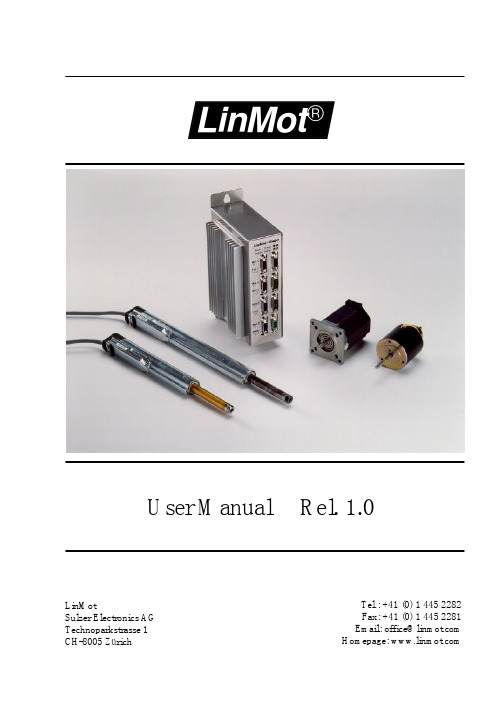
User Manual Rel. 1.0Tel.: +41 (0) 1 445 2282Fax: +41 (0) 1 445 2281Email: office@ Homepage: LinMotSulzer Electronics AGTechnoparkstrasse 1CH-8005 Zürich© 1999 Sulzer Electronics AGThis work is protected by copyright.Under the copyright laws, this publication may not be reproduced or transmitted in any form, electronic or mechanical, including photocopying, recording, microfilm, storing in an information retrieval system, not even for didactical use, or translating, in whole or in part, without the prior written consent of Sulzer Electronics AG.LinMot® is a registered trademark of Sulzer Electronics AG.NoteThe information in this documentation reflects the stage of development at the time of press and is therefore without obligation.Sulzer Electronics reserves itself the right to make changes at any time and without notice to reflect further technical advance or product improvement. Please refer to the latest edition of our “General business terms”Version 1.01 / Rev. 3 October 8th 19991.Introduction__________________________________________1-11.1Used symbols__________________________________________1-22.Safety notes__________________________________________2-12.1Installation____________________________________________2-23.System Overview_______________________________________3-1 3.1Drive system LinMot®___________________________________3-13.1.1Actuator: Linear drive LinMot®P___________________________3-23.1.2Actuator: stepper motor LinMot®Step________________________3-23.1.3Actuator: electromagnet LinMot® Magnet_____________________3-2 3.2LinMot® P: a new construction element____________________3-2 3.3Substitution possibilities of LinMot® P_____________________3-3 3.4Technical properties of LinMot® P________________________3-4 3.5Application fields of LinMot® P___________________________3-4 3.6Driving and operating modes of LinMot®___________________3-53.6.1Driving concept__________________________________________3-53.6.2Operation modes_________________________________________3-53.6.3Connection to higher-level control systems____________________3-8 3.7Protection and error behavior____________________________3-93.7.1Internal protection functions________________________________3-93.7.2Monitoring functions_____________________________________3-93.7.3Emergency stop possibilities________________________________3-93.7.4Emergency stop through supply interruption___________________3-9 3.8Operation and configuration____________________________3-103.8.1System configuration____________________________________3-103.8.2Curve generation________________________________________3-113.8.3Monitoring function (digital Oscilloscope)___________________3-123.8.4Error logbook__________________________________________3-133.9Customer specific applications___________________________3-144.Design and Installation_________________________________4-1 4.1Operating modes_______________________________________4-14.1.1Analog position setting____________________________________4-24.1.2Analog current setting____________________________________4-34.1.3Two point run___________________________________________4-34.1.4Running reference curves__________________________________4-44.1.5Set values through the serial interface________________________4-5 4.2Operating states_______________________________________4-64.2.1Operating state “Setup”___________________________________4-74.2.2Operating state “Wait for Disable”___________________________4-74.2.3Operating state “Disable”__________________________________4-74.2.4Operating state “Drive Init”________________________________4-74.2.5Operating state “Run”_____________________________________4-84.2.6Operating state “Stop”____________________________________4-84.2.7Operating state “Error”____________________________________4-8 4.3Position monitoring_____________________________________4-94.3.1Following error monitoring________________________________4-94.3.2Position range monitoring________________________________4-104.4Initialization__________________________________________4-114.4.1Linear motors of the LinMot® P series_______________________4-114.4.2Stepper motors_________________________________________4-13 4.5Signal interfaces______________________________________4-144.5.1SYS1 interface_________________________________________4-144.5.2SYS2 connector_________________________________________4-164.5.3COM connector_________________________________________4-17 4.6Actuator interfaces____________________________________4-184.6.1Connection of LinMot® P linear motors______________________4-184.6.2Connecting stepper motors________________________________4-194.6.3Connecting inductive loads________________________________4-19 4.7Connecting the power supply____________________________4-204.7.1E100/E200/E400 supply__________________________________4-204.7.2E1000/E2000/E4000 supply_______________________________4-21 4.8HW configuration of the electronic units__________________4-234.8.1Signal board configuration________________________________4-23 4.9Mechanical installation_________________________________4-254.10Constructive notes on the installation of the linear motors____4-265.Configuration Software_________________________________5-1 5.1Installation requirements________________________________5-1 5.2Installation of the configuration software___________________5-2 5.3Introduction___________________________________________5-3 5.4Login________________________________________________5-3 5.5Commander___________________________________________5-4 5.6Control Panel_________________________________________5-4 5.7Parameter Inspector____________________________________5-55.7.1Editing the parameters____________________________________5-65.7.2Saving and loading parameter sets___________________________5-75.7.3Copy and Paste__________________________________________5-75.7.4Verifying parameter settings________________________________5-85.7.5Printing parameter sets____________________________________5-85.7.6Write-protected parameters_________________________________5-95.7.7Online mode____________________________________________5-95.7.8Offline mode____________________________________________5-9 5.8Curve Inspector______________________________________5-105.8.1User interface of the Curve Inspector________________________5-105.8.2Operational elements of the Curve Inspector__________________5-105.8.3Curve Editor interface____________________________________5-135.8.4Operational elements of the Curve Editors____________________5-145.8.5Creating curves with the wizards___________________________5-165.8.6Defining reference curves in Excel__________________________5-17 5.9Oscilloscope__________________________________________5-185.9.1Setting the recording variables_____________________________5-195.9.2Setting the trigger mode__________________________________5-195.9.3Determining the sample rate_______________________________5-205.9.4Adjusting the display____________________________________5-215.9.5Starting and stopping the Oscilloscope_______________________5-215.9.6Printing recorded curves__________________________________5-215.10Error Inspector_______________________________________5-225.10.1Operational elements of the Error Inspectors__________________5-22 5.11Tutorial A: First Steps________________________________5-245.11.1Commissioning example__________________________________5-24 5.12Tutorial B: Operating the Oscilloscope___________________5-255.12.1Creating a curve________________________________________5-255.12.2Configuring the electronic unit_____________________________5-255.12.3Oscilloscope configuration for the recording of the position set value5-265.12.4Oscilloscope configuration for the following error monitoring____5-275.12.5Final remark___________________________________________5-28 5.13Tutorial C: Generating reference curves_________________5-295.13.1"Linear Out" curve______________________________________5-305.13.2"Hold" curve___________________________________________5-325.13.3"Jump Back" curve______________________________________5-335.13.4Saving curves__________________________________________5-345.13.5Merging curves_________________________________________5-345.13.6Writing curves to the electronic unit________________________5-365.14Tutorial D: Defining curves with Excel___________________5-376.Parameters___________________________________________6-17.Service______________________________________________7-11. IntroductionThis manual is organized as follows:Please take a moment to read and get accustomed with the safety instructions. Thisinformation is intended for your personal safety and should help in protecting the electronic units and linear motors from possible damage.Gives an overview of the properties and features of the single LinMot ® components and their operation.Here you will find a description of the functionality, the different operation modes and the technical data of the electronic unit. Further, the interfaces and the installation are described in this chapter. This information helps you optimally embed the LinMot ®products in your application.In this chapter you will get accustomed with the functionality and possibilities of the PC software for the configuration of the LinMot ® electronic unit. Further, you will find examples that will make the first commissioning of the system easy.This chapter gives an in-depth description of all the parameters to which you have access during the configuration of the LinMot ® electronic unit.Explains the error messages that are displayed by the LEDs and helps you in the troubleshooting.Safety notes System description Design and installation Configuration software Parameters Service1.1 Used symbolsImportant notes or tips in this manual are marked with the following symbols:Tips, notesUseful information that should make operating the devices easier is given here.CautionNon observance of these warnings can represent a danger for health or life and lead todamage or destruction of the devices and other objects.Strong magnetic fieldsWarning about magnetic materials that could cause damage to magnetic data mediumslike diskettes, credit cards, etc.2. Safety notesThe LinMot®linear drives are resources meant to be built into an electrical systems ormachines. During operation these resources have moving parts and hot surfaces fromwhich a danger of health or material damage could arise.The commissioning (putting the device into operation as specified in the application)of the linear motors is prohibited, as long as the machine does not comply with therelevant safety prescriptions.Those responsible for the safety of the plant or machine must guarantee that onlyqualified personal accustomed to working with electrical drive equipment is allowed towork on the devices in order to prevent and avoid injuries to persons and damage tothe equipment.Qualified personal are those who, as a result of their training, experience andinstruction as well as their knowledge of the relevant norms, regulations, accidentprevention prescriptions and service conditions have been entitled by the responsiblefor the safety of the plant to execute the necessary work and thereby recognize andprevent possible danger.The operation manual as well as any further manuals in the documentation of theproduct are to be followed consequently when executing the respective operations.Only tested and potential separated power supplies are allowed to be used for thevoltage supply of the LinMot® electronic units and other accessories.The electrical installation is to be done according to the relevant prescriptions. Anyfurther prescription contained in the documentation is to be observed.The linear drives must be protected from loads in excess of the specifications.Particularly during transportation great care must be taken in order to preventexcessive load or even bending of any part.Electronic devices are basically not fail-safe. The user is responsible for driving thelinear drive in a safe state in case of a failure.Inside the sliders of the linear motors are strong permanent magnets. These can causedamage or corruption to magnetical data mediums such as diskettes, credit cards, etc.These safety notes imply no claims regarding completeness. For questions andproblems please contact Sulzer Electronics AG.2.1 InstallationThe drive systems described in this operation manual are components and notserviceable or connection-ready devices or machines in terms of the device safety laws,the EMC laws or the CE machinery guidelines.The components are intended to be embedded in other machines. The ultimate mode ofaction is only defined once these components have been embedded in the user’smachine or plant. The conformity of the construction with the existing prescriptionsand laws lies under the sole responsibility of the user.The commissioning of the components is only permitted in machines or plants thatcomply with the CE machinery guidelines and/or with the relevant safety prescriptionsof the respective country.System Overview 3. System Overview3.1 Drive system LinMot®LinMot® is a modular built servo drive system that can be operated as ‘stand-alone’orin connection with commercial PLCs, PCs or other higher-level control systems.LinMot® incorporates the basic idea of the peripheral drive elements: the referencevalues are given directly by the higher-level control system in form of position setvalues, while the actual motion profiles and position control are calculated andexecuted peripheral in the LinMot® electronic unit. MS-Windows based configurationand commissioning programs release the engineers and draftsmen fromelectrotechnical detail questions and allow for quick and function oriented work.Among the actuators connectable to the LinMot® electronic units, the electromagneticdirect linear drives LinMot® P take a special position, as they offer completely newpossibilities in the machine construction and mechatronic system concept.The notions LinMot® Step and LinMot® Magnet refer to complementary drive familiesconsisting of the combination of commercially available stepper motors and magnets asactuators and LinMot® electronic units. Both stepper motors and electromagnets can beused in mixed system configurations with the LinMot® linear drives.Figure 3-1: Mixed system configuration consisting of two linear motors LinMot®P, a LinMot®E electronic unit as well as a stepper motor and an electromagnet.3.1.1 Actuator: Linear drive LinMot®PLinMot® P s are electromagnetic direct linear drives with integrated position sensingand bearing. LinMot® P linear motors are intrinsically free of mechanical play, gearingor belt wear. The enormous dynamic properties and compact construction of LinMot®P make a variety of applications and novel constructions possible.Figure 3-2: Electromagnetic direct linear motor LinMot® P3.1.2 Actuator: stepper motor LinMot®StepLinMot® Step allows the open-loop operation of commercially available two-phasestepper motors with LinMot®E electronic units.3.1.3 Actuator: electromagnet LinMot® MagnetLinMot® Magnet allows the intelligent control of electromagnets as used in short-stroke positioning elements or valves. Compared to the conventional voltage controlledoperation of electromagnets, the pull-in and release times of such elements can begreatly reduced with the use of LinMot® Magnet, by driving them over-excited duringthe transient.3.2 LinMot® P: a new construction elementMost commercially available servo drive systems only dispose of rotating motors,where the speed and in some cases the angular position are controlled. However, manyapplications don’t only need rotational movements, but linear movements too. Theconventional solution is to realize mechanical constructions based on levers, cam disks,spindles, belts etc. In which the rotational movement of the servo motor is translated ina linear movement. This way the servo drive serves basically as a ‘controlled energysource’.In this sense the LinMot® P linear drives are more than just ‘controlled energysources’: LinMot® P executes dynamic controlled and position controlled linearmovements directly, with no need for additional mechanical gearing elements.LinMot® P fulfills the mechatronic basic idea according to which the movementfunctions are executed directly, with minimal mechanical elements and right in theplace where they are needed. The motion control, i.e. the actual machine functionalityas well as the motion parameters are defined exclusively in the software and can beadjusted at any time with no need for intervention in the mechanic.3.3 Substitution possibilities of LinMot® PDepending on the application, LinMot® P can substitute the following conventionalsolutions and extend them with additional functionality due to its complete electroniccontrol:Spindle drives Cam disksMechanical levers Belt drivesPneumatic cylinders Rack-and-pinion drives3.4 Technical properties of LinMot® PThe linear drives LinMot® P are characterized by the following properties:•Connection to commercially available PLC and PC control systems•Position controlled and curve-driven operation•Dynamic properties of the drive adjustable ( v max, a max)•Extremely high dynamic specification (e.g.: continuous cyclical operation >15 Hz)•Compact, connection-ready construction with integrated sensing and bearing•Suitable for operation in rough industrial environments3.5 Application fields of LinMot® PThe linear drives LinMot® P can be used both as stand-alone systems or in connectionwith highly complex machines. The following list of application examples is thereforenot complete and gives only an insight in the variety of the possible applications:•Textile machinesWeaving machines, knitting machines, carpet machines, winding machines•Packaging machinesFood: pastries, coffee, tee, sweetsConsumer goods: office material, toysCosmetics: soap, tubesPharmaceutical: tablets, pills•Printing machinesOffset and tampon printing machines•Assembly systems•Winding machines•Handling machines•Robotics•Laboratory automation•Folding machines•Labeling machines•Newspaper and paper machines•Sorting machineryParcel and letter sorting systems, material sorting machines•….3.6 Driving and operating modes of LinMot®3.6.1 Driving conceptThe basic idea of LinMot® P consists in having the control tasks executed as peripheralas possible in order to free the higher-level control systems from unnecessary andcalculation-intensive ballast. The system configuration is therefore accordingly simple,as the higher-level control system just outputs the actual target value and monitorssome feedback information. The following sections will implicitly refer to LinMot® Plinear motors as actuators when no specific indication is provided. In this case thetarget value consists in the position set value to which the drives should move, whilethe feedback information typically represents a following error message. In the case ofstepper motors and electromagnets these statements can be interpreted by analogy.Ref. positionError messageSignal circuitry supplyPower circuitry supplyFigure 3-3: LinMot®’s peripheral position control frees the higher-level controlsystem from calculation intensive tasks.3.6.2 Operation modesDifferent modes of operation are available to the user. These allow optimal embeddingof the actuators in the control concept of the machine and the respective application.The LinMot® AT software currently supports the following modes of operation:•direct digital reference value setting•setting two target values depending on a high/low signal•executing two predefined curves based on a trigger signal•continuous operation, e.g. periodical execution of a curveIn all these modes a filter can be connected in order to limit the derived signals like forexample the speed or acceleration. The following table shows typical applicationexamples for the different modes of operation.3.6.3 Connection to higher-level control systemsThe electronic units LinMot®E can be controlled by higher-level control systemsdirectly by means of analog or digital input/output signal lines. The necessaryparameterisation is done with the LinMot® Talk software via an RS-232 connection.Networking via CAN-bus or RS-232 is also possible on specific customer request.Figure 3-4: Connecting LinMot® to an higher-level control system3.7 Protection and error behavior3.7.1 Internal protection functionsThe integrated sensors and complex monitoring programs allow the detection andhandling of thermal overloading of the LinMot®E and P components by means ofwarning and/or error messages. There is further the possibility to monitor the voltagesupply of the LinMot®E electronic units for overvoltage and undervoltage. If thehigher-level control system does not respond to the warning and error messages, theactuators will be shut down for safety reasons.3.7.2 Monitoring functionsThe so-called following error monitoring and the position range monitoring offer twopowerful functions for the monitoring of the actual movement processes.Following error monitoring Position range monitoring3.7.3 Emergency stop possibilitiesFrom the point of view of the higher-level control system there are two ways to handlethe LinMot® actuators in case of an emergency stop:•With the so-called FREEZE signal the drives can be stopped and maintained intheir current position. The movement is resumed when the FREEZE signalbecomes inactive again.•By means of the STOP signal the drives can be driven to a predefined emergencystop position or shut down.3.7.4 Emergency stop through supply interruptionAs the LinMot® electronic units feature separate supplies for the signal circuitry andthe power circuitry, an emergency stop can also be forced by directly interrupting thepower supply to the power circuits. As long as the signal circuitry remains powered,the initialization and actual position of the LinMot® P actuators are not lost. Thereforeit is possible to resume operation without needing to re-initialize the drives.3.8 Operation and configuration3.8.1 System configurationThe configuration and commissioning of the LinMot ® systems is done by means of the MS-Windows based software LinMot ® Talk . All the parameters can be displayed clearly, selected and edited with LinMot ® Talk by simple clicking with the mouse. As all the parameters are stored in the electronic unit, they can be recalled, analyzed and changed at any time. Creating duplicates of parameters and parameter files to be archived is equally easy. Password protection protects the data from illegitimate access.Figure 3-5: Parameter Inspector windowPrintPathActual parameter Value of the parameter Update button3.8.2 Curve generationPredefined reference curves can be executed on trigger signals in different operatingmodes. The shapes of these curves can be generated automatically by means of theCurve Creator, or can be edited manually point by point as Excel tables.Edit buttons Close buttons Graph buttonsFigure 3-6: Reference curves can be generated semi-automatically3.8.3 Monitoring function (digital Oscilloscope)Quick commissioning and optimization of a LinMot ® system is supported by the built-in monitoring function. With it, the reference curves can be compared with the movements actually executed with no need for additional sensors, etc. The differences between the two curves can give indirect hints on counteracting forces and friction forces which can be useful when adjusting the controller parameters. The operation and look of the monitoring function correspond to those of modern digital oscilloscopes.Figure 3-7: Motion analysis with the integrated digital Oscilloscope Variablespanel Trigger panel Sample rate panel Display panel3.8.4 Error logbookThanks to the system clock built in the LinMot®E electronic units the errors that haveoccurred during operation can be logged on a time basis. The information is stored inthe non volatile memory and allows a later reconstruction of the events.Figure 3-8: Error messages are saved to the logbook for later analysis.3.9 Customer specific applicationsThe goal in the basic philosophy of LinMot® is to be able to cover the broadest rangeof applications simply by configuring the basic system, without special customerspecific adjustments. In some cases (big series, special system environments) howevercustomer specific adjustments can make sense. In these cases the necessaryinterventions have to be carried out by the manufacturer.In most cases the customer specific changes will be realized in the software of theelectronic unit (‘Customized Application Software’). In most cases this will relate tothe following two requirements:•Additional control functions•Networking with customer specific bus systems ( CAN-Bus, RS-232)Figure 3-9: Structure of the LinMot®software: The manufacturer can realizespecial customizations in a special software segment (‘Customized ApplicationSoftware’).4. Design and InstallationThis chapter discusses the different possibilities for driving the LinMot®products froma higher-level control system as well as the operating states of the control electronicunit in detail. Further, the interfaces and the installation are described in order to getfamiliar with the possibilities of the LinMot® products and be able to optimally embedthem in the application.This chapter shows the basic functions of the LinMot system explaining the –ATfunctionality as an introduction. For extended functionality of –MT and –DP electronicunits, please read the manual for SW Rel. 1.3.4.1 Operating modesA wide range of operating modes are available for driving (setting the referencevalues) the actuators connected to the electronic unit. The desired set values can begiven directly through an analog interface, or else they can be stored in the electronicunit in form of curves and tables, that can be run on a digital trigger signal from thehigher-level control system.Figure 4-1: Operating modes of the LinMot electronic unitA detailed description of the operating modes that can be configured for eachconnected motor individually is given in the following chapters. The operating modesdiffer according to the different actuators linear motor LinMot® P, stepper motor andinductive load (magnet, valve, ...) and are therefore treated separately.。
DMC-9940直线电机调试指南
入门指南We M o v e t h e Wo r l dDMC-9940Manual Rev. 1.0cBy Powerly Motion TechnologiesRev 06-03第一章简介-----------------------------------------------------------------------------------------------错误!未定义书签。
一. 楔子--------------------------------------------------------------------------------------------------------------------------2二. 推荐 DMC-9940-----------------------------------------------------------------------------------------------------------2三. 介绍 DMC-9940-----------------------------------------------------------------------------------------------------------2 第二章快速入门-----------------------------------------------------------------------------------------错误!未定义书签。
一. 所需的组件:----------------------------------------------------------------------------------------------------------------5二. 安装:-------------------------------------------------------------------------------------------------------------------------5三. 使用软件:-----------------------------------------------------------------------------------------------------------------7 第三章硬件连接-----------------------------------------------------------------------------------------错误!未定义书签。
中控直线电机电子绞边使用说明书简述
中控线性电子绞边控制器控制V1.1操作手册一、 电子绞边控制板接口分布图:图2. 1 分布图按键说明:M 键:显示模式切换,可以在状态显示模式、Pnxxx 、Fnxxx 、Unxxx 之间切换。
U 键:使闪烁位数字往上增加1。
D 键:使闪烁位数字往下减1。
1+1- 2+2-- + +V -+V -反馈输入2反馈输入1电源36V电机电源接口D B 25脉冲指令输入MDS/EU状态显示模式辅助功能执行模式参数设定模式监视模式 电源ONS 键:短按:切换数据位;长按:进入或退出数据模式或菜单模式,保存更改数据。
状态显示模式说明省略符号显示内容伺服准备就绪状态电机运行中… 报警状态:显示报警代码,参考第五章其中在伺服准备就绪状态和电机运行中,数码管前两位显示了电机运行状态,如下所示:参数(Pn***)设置操作说明参数所对应的功能参考第六章,以设置微动速度为600例子,说明如何操作 1. 按M 键,使功能切换到Pn304,2. 长按S/E 键,进入Pn304,此时显示的微动速度(默认是300)3. 短按S/E 键,切换显示位置,使其百位闪烁,按U 键,由3改变到64. 长按S/E 键,设置参数成功二、 电子绞边配线3.1端子说明DB25端子说明:表3. 1端子序号 功能13 绞边1控制输入端,下降沿有效 25 绞边2控制输入端,下降沿有效 12 织机预开车信号24绝对式光电编码器高位第7比特输入省略符号比特数据电机2位置显示 电机1位置显示11 绝对式光电编码器高位第6比特输入23 绝对式光电编码器高位第5比特输入10 绝对式光电编码器高位第4比特输入22 绝对式光电编码器高位第3比特输入9 绝对式光电编码器高位第2比特输入21 绝对式光电编码器高位第1比特输入8 绝对式光电编码器高位第0比特输入7、20 24V控制电源输入19 ALM+光耦输出正端6 ALM-光耦输出负端18 CANH5 CANL●反馈输入端子说明:端子序号功能FB1-1 5V输出FB1-2 绞边1反馈输入FB1-3 地FB2-1 5V输出FB2-2 绞边2反馈输入FB2-3 地●电源输入端子说明:端子序号说明功能1 36V电源正端2 36V电源地●电机动力输出端子说明:注:该端子无正负输入区别,控制器内部可以自动识别端子序号说明功能J1-1 绞边器1电机动力线输出1J1-2 绞边器1电机动力线输出2J1-3 绞边器2电机动力线输出1J1-4 绞边器2电机动力线输出2 三、报警代码一览表报警代号解决办法A00 电机1动力线断A01 电机2 动力线断A02 过电流A03 电机1位置超差A04 电机2位置超差A05 电机1位置反馈异常查看电机反馈线或动力线有接错A06 电机2位置反馈异常查看电机反馈线或动力线有接错A07 电机1定位误差过大A08 反馈线断线电机2定位误差过大A11A12 电机1反馈断线A13 电机2反馈断线四、控制参数一览表(Pn500是设置绞边使用选择)Pn000 选择控制方式设置范围:0~2000出厂设置:0说明:本产品包含了IO控制和CAN控制,派生出了不同的控制方式。
Hiwin最新直线电机力矩电机选型手册技术样本1107版
工業機器人
Single Axis Robot
• KK 半導體、電子化系列 • KS, KA 自動化系列
空氣軸承線性馬達定位 平台
Linear Motor Air Bearing Platform
2008年台灣精品金質獎 2007, 2002年台灣精品銀質獎
線性滑軌 Linear Guideway
HG/EG/RG/MG 系列 精密機械/電子半導體/生技醫療 • E2 環保潤滑模組 • Q1 靜音式 • A1 氣淨式
以下列舉了許多不同的應用案例,不單是機構部分的特殊訂製可 以提供,在某些情形下,我們也可以提供伺服控制的整體解決提 案以達到整體生產過程的最佳化。
1.1 實績案例
合理價格的取放及檢測用龍門定位系統
X Y 龍門架構使得許多應用得以更低的成本來實現,以標準元件 構築而成的龍門定位平台。 採用LMX1L系列的定位軸 重現性±2µm 可提供含底座
微米技術及晶圓處理
在微米工程等級的應用以及晶圓設備中尤其重視絕對精度及 潔淨室適用性。採用線性馬達高精度XY平台為最佳選擇。 行程200 mm x 200 mm, 亦可選購 300 mm x 300 mm 全行程平面度±4µm 各軸重現性±1µm 各軸精度±4µm 潔淨室等級100適用, 亦可選購等級10
另一AOI光學檢測應用, 客戶需求要高性能價格比 534mm × 534mm^2行程 LMS27及LMS13龍門 特殊龍門同動控制 鋼材框架 集成線路板輸送, PLC, IPC於客戶端 次微米級重現性 承諾40mm移動可於200ms內收歛至±1.5μm
4
M99TC04-1005
客製玻璃加工機台
線性馬達機台被設計用來承載工作水頭在平台上方移動, 客戶的工作 水頭用來切割雙層玻璃 同動架構線性馬達定位機台() 1300mm × 1450mm行程 平滑運動 正弦波整流, 無頓力 LMC系列馬達 各軸重現性±2μm 剛性機構底座
直线电机平台系列安全操作及保养规程
直线电机平台系列安全操作及保养规程一、前言直线电机平台系列是一种应用广泛的直线推力设备,适用于各种需要做匀速直线移动和定位的场合。
在使用直线电机平台系列设备时,为了确保设备的安全和使用寿命,必须严格遵守安全操作规程和保养维护规程。
本文档将详细介绍直线电机平台系列设备的安全操作规程和保养维护规程,以供使用者参考和遵循。
二、安全操作规程1.设备操作前的准备在使用直线电机平台系列设备前,必须进行以下准备:1.在操作前先确认设备的操作手册及使用说明书;2.确保设备与电源配套,连接接头无松动;3.确认设备无异常后再进行操作;4.正确设置设备工作参数;5.将安全警示标志设置在显眼的位置,并确保被操作者已经知道相关安全注意事项;6.确认设备操作员已经接受相关的培训,具备设备实际操作能力。
2.设备的正常操作1.在设备运行时,操作员必须保持集中注意力,妥善反应异常情况;2.不能在设备运行时随意操作;3.操作者不得长时间离开设备;4.在设备运行时,必须按照规定方法操作设备,严禁超范围使用设备;5.随时注意设备的工作情况,发现异常情况及时停止设备的运行;6.操作者需要注意,设备启动后,必须等待其运行到规定位置后方能进行下一步操作;7.实际操作时,设备必须保持稳定、无晃动,不得进行抖动或过大的冲击。
3.设备的正常关闭和维护1.在关闭设备时,应按规定步骤进行;2.关闭电源时,必须先关闭设备的程序;3.维护设备时,必须按照工作手册进行,并禁止进行私自操作。
三、保养维护规程1.日常保养1.定期清洁设备外部的杂物;2.定期检查机身的固定螺丝,以防松动;3.定期检查设备的轨道是否有杂物,稍有杂物就应清理干净;4.定期检查设备的传动杆端面及其与轨道的配合处是否正常,并确认其未失效;5.定期清理及检查轻负载装置表面是否有杂物。
2.周年保养1.拆卸清洗外壳及内部所有零件;2.安装灰尘滤清器;3.润滑流动部件,并更换润滑油;4.对传动杆进行更换。
直线电机驱动器说明书

地址(Address):深圳市南山区高新科技园北区朗山二路 6 号赛霸电子一号楼四楼(4/F,1st CYBIO Building, No. 6 Langshan 2 Road,
Hi-Tech Industrial Park North, Nanshan, Shenzhen, Guangdong,P.R.China)
电 话 (Tel) :(86)(755)26982158
传真(Fax):(86)(755)26982786 邮政编码(Postcode):518057
① 用于与生命相关的医疗器械。 ② 用于可能造成人身安全的设备,例如:火车或升降机。 ③ 用于可能造成社会影响的计算机系统 ④ 用于有关对人身安全或对公共设施有影响的其他设备。 (5).对用于易受震动的环境,例如:交通工具上操作,请咨询我们。
1.2 安全注意事项
(1).请勿在易燃易爆的环境下操作本产品,否则易造成伤害或引起火灾。 (2).绝不要触摸驱动器内部任何部件,否则会触电。 (3).在通电情况下,不要进行维修和检查工作,也勿整理电线。如果要的话,至少得提前五分 钟把电源关掉,否则,会有触电危险。 (4).在运输、安装、接线、操作、维修和检查等各方面,请咨询相应的专家。若没有相应专业 技术人员,很可能会发生触电、受到伤害或是引起火灾。 (5).一定要使驱动器 PE 端子(保护接地)接地,电机的接地端子必须要与驱动器的 PE 端子(保 护接地)相连。否则,会出现触电情况。 (6).通电时,绝不要靠近也不要触及接线端子,更不要移动任何接线端子,否则会发生触电。 (7).要安全正确布线,符合电气安装技术标准和附加规则。否则,可能引起短路和火灾。 (8).当报警发生后,须排除故障的起因,检查系统的安全性。然后,报警复位,才能继续操作。 否则,可能受到伤害。 (9).检查电源规格是否规范,否则会出现故障。 (10).在接通电源长时间后或断开电源时间不长时,请勿触及驱动器散热片。否则可能会被灼伤。 (11).需要维修,请与我们联系。如果自己拆卸部件,部件可能会出故障。
parker直线电机 使用手册
parker直线电机使用手册parker直线电机是一种先进的电动驱动设备,具有高效、精准、稳定的特点。
本使用手册旨在为用户提供关于parker直线电机的详细操作说明和注意事项,帮助用户正确、安全地使用该设备。
正文一、产品概述parker直线电机是一种采用直线运动原理的电动驱动器,可广泛应用于机械加工、自动化装配、医疗器械等领域。
该电机具有结构紧凑、功耗低、响应速度快等优点,能够实现高精度直线运动控制。
二、安装与调试1. 安装前,请确保电机和控制器的电源已经断开,并按照说明书的要求选择适当的安装位置。
2. 仔细检查电机是否有损坏或松动的部件,如有发现问题,请及时联系售后服务。
3. 将parker直线电机正确安装到设备上,并确保固定牢固。
4. 进行电机参数的设置和调试,根据实际需求调整电机的运动速度、加速度等参数。
三、使用注意事项1. 在使用过程中,请勿超载使用电机,以免造成设备损坏或安全事故。
2. 使用前,请确保电机和控制器的电源稳定,并按照标准接线图正确接线。
3. 长时间不使用电机时,请切断电源,以免造成能耗浪费和设备损坏。
4. 请定期对电机进行维护保养,保持电机的清洁和良好的工作状态。
5. 若发现电机运行异常或故障,请及时联系售后服务,不要自行拆卸或修复。
四、售后服务1. 如果在使用过程中遇到任何问题,可随时联系售后服务。
2. 请提供详细的问题描述和相关信息,以便售后服务能够及时有效地给予帮助。
3. 售后服务将尽快解决您的问题,并提供技术支持和维修服务。
【文档结尾】本使用手册详细介绍了parker直线电机的安装、调试和使用注意事项,希望能够帮助用户正确、安全地操作该设备。
如有更多问题,请随时联系售后服务。
西门子1FN1直线电机的参数配置及转子位置同步丁堪雄西门子工厂

西门子1FN1直线电机的参数配置及转子位置同步丁堪雄(西门子工厂自动化工程有限公司,100016)中图分类号:TM359.4 文献标识码:B 文章编号:1004-0420(2009)01-0011-040前言目前,市场上高速高精加工机床的进给驱动,主要由传统的旋转伺服电机和精密高速滚珠丝杠组成,从伺服电机到移动部件间有一系列机械元件,势必存在弹性变形、摩擦和反向间隙,相应造成运动滞后和其他非线性误差,而且滚珠丝杠副的移动速度和加速度已提高接近极限。
直线电机的出现,实现了机床直线轴的直接驱动,取消了连轴节、齿轮等中间传动的机械部件,减少了机械误差,而且直线电机最大加速度可达30 g,最高速度可达4 m/s,极大提高了机床的动态响应和刚性,使机床可达到更高的定位精度和轮廓精度。
西门子推出的1FN系列直线电机,可以和SIMODRIVE611D或SIMODRIVE611U系列驱动器结合使用,本文主要介绍西门子840D系统采用1FN1直线电机的参数配置及转子位置同步的方法。
1 840D系统SIMODRIVE611D驱动器和1FN直线电机的连接,如图1所示。
图1直线电机连接示意图2 驱动器的配置在西门子MMC103或PCU50的操作窗口中,按如下软健:/启动Start-up/机床数据Machine data/驱动配置Drive config/,按插入模块键insert_module,按OK键。
输入逻辑驱动器号logic drive number,选择驱动器类型drive type:(SLM=synchroner linear motor 1FN1XXX),按选择功率模块power_section键,选择实际安装的功率模块power module,按保存save键。
3 轴数据的设置在西门子MMC103或PCU50的操作窗口中,按如下软键:/启动/机床数据/轴数据Axis_MD/,进入当前轴的轴参数窗口,调整以下参数:MD30130 CTRLOUT _ TYPE=1(控制器输出类型)MD30240编码器类型ENC_TYPE=1(LS186,LS486海德汉光栅尺型号)=4(LC181海德汉光栅尺型号)MD31000编码器是光栅尺_LINEAR=1MD31010光栅尺栅距ENC_DRID_POINT_DIST=0.02mm(LS486)=0.016mm(LC181)MD32110反馈极性ENC_FEEDBACK_POL=1=-1 (实际值取反)MD34200返回参考点方式ENC _REFP_MODE=1(LS486)=0(LC181)按NCK 复位NCK-Reset键,按YES键。
- 1、下载文档前请自行甄别文档内容的完整性,平台不提供额外的编辑、内容补充、找答案等附加服务。
- 2、"仅部分预览"的文档,不可在线预览部分如存在完整性等问题,可反馈申请退款(可完整预览的文档不适用该条件!)。
- 3、如文档侵犯您的权益,请联系客服反馈,我们会尽快为您处理(人工客服工作时间:9:00-18:30)。
直线电机技术手册
直线电机是一种将电能转换为直线机械运动的电机。
它具有结构简单、体积小、可调速、低噪音、高效率等优点,被广泛应用于自动化设备、机器人、医疗器械等领域。
本技
术手册将介绍直线电机的基本原理、分类、工作原理、应用以及性能参数等内容。
第一篇:直线电机的基本原理
直线电机是由电力驱动产生直线运动的装置。
它主要由定子和活子构成,其中定子固
定在机械结构上,活子则与定子直接相连接并作为可移动部分。
根据运动方式的不同,直
线电机可分为平面直线电机和圆柱直线电机两种。
平面直线电机主要用于平面直线运动,
而圆柱直线电机则用于圆柱直线运动。
第二篇:直线电机的分类
直线电机根据工作方式的不同可分为直线感应电机、直线同步电机、直线步进电机等。
直线感应电机是利用电磁感应原理工作的,它通过交流电产生的感应电磁场来产生运动。
直线同步电机则是利用电磁场和永磁体之间的作用力来进行直线运动。
直线步进电机则是
利用电磁铁和永磁铁之间的吸引力和排斥力来产生直线运动。
第三篇:直线电机的工作原理
直线电机的工作原理与旋转电机类似,都是利用电磁感应或者磁场作用力来产生直线
运动。
直线电机通过一个交流电源来产生电磁感应场或者磁场,然后利用电磁感应场或者
磁场和永磁场之间的作用力来进行直线运动。
直线电机的运动速度可以通过改变电源频率
或者改变磁场强度来调节。
第四篇:直线电机的应用
直线电机具有结构简单、体积小、可调速、低噪音、高效率等优点,因此被广泛应用
于自动化设备、机器人、医疗器械等领域。
在工业自动化领域,直线电机通常用于驱动输
送带、自动检测设备、机械臂等。
在医疗器械领域,直线电机通常用于驱动高精度位置调
整系统、手术机器人等。
第五篇:直线电机的性能参数
直线电机的性能参数包括最大力矩、最大速度、加速度、精度等。
最大力矩是指直线
电机产生的最大驱动力;最大速度是指直线电机能够达到的最大运动速度;加速度是指直
线电机的加速能力;精度是指直线电机能够实现的运动精度。
这些性能参数对于直线电机
的应用非常重要,可以根据不同的需求来选择合适的直线电机。
总结:
本技术手册介绍了直线电机的基本原理、分类、工作原理、应用以及性能参数等内容。
直线电机具有结构简单、体积小、可调速、低噪音、高效率等优点,在自动化设备、机器人、医疗器械等领域被广泛应用。
了解直线电机的基本原理和工作原理对于选择合适的直
线电机非常重要。
希望本技术手册能对读者有所帮助。
