rfc2382.A Framework for Integrated Services and RSVP over ATM
RFC1122-A(中文版)

本文档中指出的要求是为能完成完备的功能的因特网 主机而设计的,能够通过任意的因特网通路达到完备的互用 性。
1.1.3 IP 协议簇 使用因特网系统进行桶金,主机必须实现由 IP 协议簇组成的分层协
议集合。主机每层必须至少实现一个协议。 因特网体系结构中使用的隔层协议[INTRO:4]主要有: 1. 应用层 应用层是 IP 协议簇中的最高层。虽然有一些因特网应用层协议 确实包含了一些内部的子层划分,但基于因特网的软件集并没有再把 应用层再划分子层。因特网软件集中的应用层协议必须包含最高两层 --表示层和应用层--根据 OSI 参考模型的规定。 我们将应用层协议分为两类:直接为用户提供服务的用户协议和 提供系统功能的支持协议。对于用户和支持协议的要求将在相关的 RFC 文档中找到[INTRO:1]。 最常使用的因特网用户协议包括: a)Telnet(用于远程登录) b)FTP(用于文件传输) c)SMTP(电子邮件发送) 同时还有许多标准化的用户协议[INTRO:4]和许多私有用户协议。 支持协议用于主机的名字映射,导入和管理,包括 SNMP、BOOTP、 RARP 和 DNS(域名系统)协议。 2. 传输层 传输层为应用层提供了端到端的通信服务。现在主要有两种传输 层协议: a)传输控制协议()TCP0 b)用户数据报协议(UDP) TCP 是面向连接的传输服务提供端到端的可靠传输,重新排序和 流控制。UDP 是一个面向非连接的传输服务。 传输层协议将在第四章中进行讨论。 3. 网络层 所有的因特网传输层协议都使用了 IP 协议将数据由源主机传送 至目的主机。IP 指一个面向非连接的网络服务,不提供端到端的保证。
BGP4+与BGP4的区别_IPv6技术、部署与业务应用_[共2页]
![BGP4+与BGP4的区别_IPv6技术、部署与业务应用_[共2页]](https://img.taocdn.com/s3/m/849ec892b307e87100f69692.png)
65 BGP 协议的实现没有要求必须要使用哪种算法来进行路径选择。
因为,BGP 的RFC 中只声明了路径计算要遵循的某些原则,但没有确定具体的算法。
4.4.2 BGP4+与BGP4的区别为了提供对多种网络层协议的支持,IETF 对BGP4进行了扩展,形成BGP4+。
BGP4+由以下规范予以定义。
RFC 1771,A Border Gateway Protocol 4 (BGP-4)RFC 1772,Application of the Border Gateway Protocol in the InternetRFC 1966,BGP Route Reflection: An Alternative to Full-Mesh IBGPRFC 1997,BGP Communities AttributeRFC 2270,Using a Dedicated AS for Sites Homed to a Single ProviderRFC 2283,Multiprotocol Extensions for BGP-4RFC 2385,Protection of BGP Sessions via the TCP MD5 Signature OptionRFC 2439,BGP Route Flap DampingRFC 2545,Use of BGP-4 Multiprotocol Extensions for IPv6 Inter-Domain RoutingRFC 2796,BGP Route ReflectionRFC 3065,Autonomous System Confederations for BGPCapabilities Negotiation with BGP4,IETF draft draft-ietf-idr-cap-neg-01BGP Extended Communities Attribute ,IETF draft-ramachandra-bgp-ext-communities-04.txt BGP4+ Peering Using IPv6 Link-local Address ,draft-kato-bgp-ipv6-link-local-00.txtIPv6利用BGP 的多协议扩展属性,达到在IPv6网络中应用的目的,BGP 协议原有的消息机制和路由机制没有改变。
rfc3262-Reliability of Provisional Responses In SIP
Network Working Group J. Rosenberg Request for Comments: 3262 dynamicsoft Category: Standards Track H. SchulzrinneColumbia U.June 2002Reliability of Provisional Responsesin the Session Initiation Protocol (SIP)Status of this MemoThis document specifies an Internet standards track protocol for theInternet community, and requests discussion and suggestions forimprovements. Please refer to the current edition of the "InternetOfficial Protocol Standards" (STD 1) for the standardization stateand status of this protocol. Distribution of this memo is unlimited.Network Communication Protocol Map. To order: /map.html Easy to use sniffing tool: /packet.htmlCopyright Notice Copyright (C) The Internet Society (2002). All Rights Reserved.AbstractThis document specifies an extension to the Session InitiationProtocol (SIP) providing reliable provisional response messages.This extension uses the option tag 100rel and defines the ProvisionalResponse ACKnowledgement (PRACK) method.Table of Contents1 Introduction (2)2 Terminology (3)3 UAS Behavior (3)4 UAC Behavior (6)5 The Offer/Answer Model and PRACK (9)6 Definition of the PRACK Method (10)7 Header Field Definitions (10)7.1 RSeq (10)7.2 RAck (11)8 IANA Considerations (11)8.1 IANA Registration of the 100rel Option Tag (11)8.2 IANA Registration of RSeq and RAck Headers (12)9 Security Considerations (12)10 Collected BNF (12)11 Acknowledgements (12)12 Normative References (13)13 Informative References (13)14 Authors' Addresses (13)15. Full Copyright Statement (14)1 IntroductionThe Session Initiation Protocol (SIP) (RFC 3261 [1]) is a request-response protocol for initiating and managing communicationssessions. SIP defines two types of responses, provisional and final. Final responses convey the result of the request processing, and are sent reliably. Provisional responses provide information on theprogress of the request processing, but are not sent reliably in RFC 3261.It was later observed that reliability was important in severalcases, including interoperability scenarios with the PSTN.Therefore, an optional capability was needed to support reliabletransmission of provisional responses. That capability is provided in this specification.The reliability mechanism works by mirroring the current reliability mechanisms for 2xx final responses to INVITE. Those requests aretransmitted periodically by the Transaction User (TU) until aseparate transaction, ACK, is received that indicates reception ofthe 2xx by the UAC. The reliability for the 2xx responses to INVITE and ACK messages are end-to-end. In order to achieve reliability for provisional responses, we do nearly the same thing. Reliableprovisional responses are retransmitted by the TU with an exponential backoff. Those retransmissions cease when a PRACK message isreceived. The PRACK request plays the same role as ACK, but forprovisional responses. There is an important difference, however.PRACK is a normal SIP message, like BYE. As such, its ownreliability is ensured hop-by-hop through each stateful proxy. Also like BYE, but unlike ACK, PRACK has its own response. If this were not the case, the PRACK message could not traverse proxy serverscompliant to RFC 2543 [4].Each provisional response is given a sequence number, carried in the RSeq header field in the response. The PRACK messages contain anRAck header field, which indicates the sequence number of theprovisional response that is being acknowledged. The acknowledgments are not cumulative, and the specifications recommend a singleoutstanding provisional response at a time, for purposes ofcongestion control.Rosenberg & Schulzrinne Standards Track [Page 2]2 TerminologyIn this document, the key words "MUST", "MUST NOT", "REQUIRED","SHALL", "SHALL NOT", "SHOULD", "SHOULD NOT", "RECOMMENDED", "MAY", and "OPTIONAL" are to be interpreted as described in RFC 2119 [2] and indicate requirement levels for compliant SIP implementations.3 UAS BehaviorA UAS MAY send any non-100 provisional response to INVITE reliably, so long as the initial INVITE request (the request whose provisional response is being sent reliably) contained a Supported header field with the option tag 100rel. While this specification does not allow reliable provisional responses for any method but INVITE, extensions that define new methods that can establish dialogs may make use ofthe mechanism.The UAS MUST send any non-100 provisional response reliably if theinitial request contained a Require header field with the option tag 100rel. If the UAS is unwilling to do so, it MUST reject the initial request with a 420 (Bad Extension) and include an Unsupported header field containing the option tag 100rel.A UAS MUST NOT attempt to send a 100 (Trying) response reliably.Only provisional responses numbered 101 to 199 may be sent reliably. If the request did not include either a Supported or Require header field indicating this feature, the UAS MUST NOT send the provisional response reliably.100 (Trying) responses are hop-by-hop only. For this reason, the reliability mechanisms described here, which are end-to-end,cannot be used.An element that can act as a proxy can also send reliable provisional responses. In this case, it acts as a UAS for purposes of thattransaction. However, it MUST NOT attempt to do so for any request that contains a tag in the To field. That is, a proxy cannotgenerate reliable provisional responses to requests sent within the context of a dialog. Of course, unlike a UAS, when the proxy element receives a PRACK that does not match any outstanding reliableprovisional response, the PRACK MUST be proxied.There are several reasons why a UAS might want to send a reliableprovisional response. One reason is if the INVITE transaction will take some time to generate a final response. As discussed in Section 13.3.1.1 of RFC 3261, the UAS will need to send periodic provisional responses to request an "extension" of the transaction at proxies.The requirement is that a proxy receive them every three minutes, but Rosenberg & Schulzrinne Standards Track [Page 3]the UAS needs to send them more frequently (once a minute isrecommended) because of the possibility of packet loss. As a more efficient alternative, the UAS can send the response reliably, inwhich case the UAS SHOULD send provisional responses once every two and a half minutes. Use of reliable provisional responses forextending transactions is RECOMMENDED.The rest of this discussion assumes that the initial requestcontained a Supported or Require header field listing 100rel, andthat there is a provisional response to be sent reliably.The provisional response to be sent reliably is constructed by the UAS core according to the procedures of Section 8.2.6 of RFC 3261. In addition, it MUST contain a Require header field containing the option tag 100rel, and MUST include an RSeq header field. The value of the header field for the first reliable provisional response in a transaction MUST be between 1 and 2**31 - 1. It is RECOMMENDED that it be chosen uniformly in this range. The RSeq numbering space is within a single transaction. This means that provisional responses for different requests MAY use the same values for the RSeq number.The reliable provisional response MAY contain a body. The usage of session descriptions is described in Section 5.The reliable provisional response is passed to the transaction layer periodically with an interval that starts at T1 seconds and doubles for each retransmission (T1 is defined in Section 17 of RFC 3261). Once passed to the server transaction, it is added to an internallist of unacknowledged reliable provisional responses. Thetransaction layer will forward each retransmission passed from the UAS core.This differs from retransmissions of 2xx responses, whoseintervals cap at T2 seconds. This is because retransmissions of ACK are triggered on receipt of a 2xx, but retransmissions ofPRACK take place independently of reception of 1xx.Retransmissions of the reliable provisional response cease when amatching PRACK is received by the UA core. PRACK is like any other request within a dialog, and the UAS core processes it according to the procedures of Sections 8.2 and 12.2.2 of RFC 3261. A matching PRACK is defined as one within the same dialog as the response, and whose method, CSeq-num, and response-num in the RAck header fieldmatch, respectively, the method from the CSeq, the sequence number from the CSeq, and the sequence number from the RSeq of the reliable provisional response.If a PRACK request is received by the UA core that does not match any unacknowledged reliable provisional response, the UAS MUST respond to the PRACK with a 481 response. If the PRACK does match anunacknowledged reliable provisional response, it MUST be responded to with a 2xx response. The UAS can be certain at this point that the provisional response has been received in order. It SHOULD ceaseretransmissions of the reliable provisional response, and MUST remove it from the list of unacknowledged provisional responses.If a reliable provisional response is retransmitted for 64*T1 seconds without reception of a corresponding PRACK, the UAS SHOULD reject the original request with a 5xx response.If the PRACK contained a session description, it is processed asdescribed in Section 5 of this document. If the PRACK insteadcontained any other type of body, the body is treated in the same way that body in an ACK would be treated.After the first reliable provisional response for a request has been acknowledged, the UAS MAY send additional reliable provisionalresponses. The UAS MUST NOT send a second reliable provisionalresponse until the first is acknowledged. After the first, it isRECOMMENDED that the UAS not send an additional reliable provisional response until the previous is acknowledged. The first reliableprovisional response receives special treatment because it conveysthe initial sequence number. If additional reliable provisionalresponses were sent before the first was acknowledged, the UAS could not be certain these were received in order.The value of the RSeq in each subsequent reliable provisionalresponse for the same request MUST be greater by exactly one. RSeq numbers MUST NOT wrap around. Because the initial one is chosen to be less than 2**31 - 1, but the maximum is 2**32 - 1, there can be up to 2**31 reliable provisional responses per request, which is morethan sufficient.The UAS MAY send a final response to the initial request beforehaving received PRACKs for all unacknowledged reliable provisionalresponses, unless the final response is 2xx and any of theunacknowledged reliable provisional responses contained a sessiondescription. In that case, it MUST NOT send a final response until those provisional responses are acknowledged. If the UAS does send a final response when reliable responses are still unacknowledged, it SHOULD NOT continue to retransmit the unacknowledged reliableprovisional responses, but it MUST be prepared to process PRACKrequests for those outstanding responses. A UAS MUST NOT send newreliable provisional responses (as opposed to retransmissions ofunacknowledged ones) after sending a final response to a request.4 UAC BehaviorWhen the UAC creates a new request, it can insist on reliabledelivery of provisional responses for that request. To do that, it inserts a Require header field with the option tag 100rel into the request. A Require header with the value 100rel MUST NOT be present in any requests excepting INVITE, although extensions to SIP mayallow its usage with other request methods.Header field where PRACK___________________________________Accept R oAccept 2xx -Accept 415 cAccept-Encoding R oAccept-Encoding 2xx -Accept-Encoding 415 cAccept-Language R oAccept-Language 2xx -Accept-Language 415 cAlert-Info R -Alert-Info 180 -Allow R oAllow 2xx oAllow r oAllow 405 mAuthentication-Info 2xx oAuthorization R oCall-ID c mCall-Info -Contact R -Contact 1xx -Contact 2xx -Contact 3xx oContact 485 oContent-Disposition oContent-Encoding oContent-Language oContent-Length tContent-Type *CSeq c mDate oError-Info 300-699 oExpires -From c mIn-Reply-To R -Max-Forwards R mMin-Expires 423 -MIME-Version oOrganization -Table 1: Summary of header fields, A--OHeader field where PRACK__________________________________________Priority R -Proxy-Authenticate 407 mProxy-Authenticate 401 oProxy-Authorization R oProxy-Require R oRecord-Route R oRecord-Route 2xx,18x oReply-To -Require cRetry-After 404,413,480,486 o500,503 o600,603 oRoute R cServer r oSubject R -Supported R oSupported 2xx oTimestamp oTo c mUnsupported 420 mUser-Agent oVia c mWarning r oWWW-Authenticate 401 mTable 2: Summary of header fields, P--ZIf the UAC does not wish to insist on usage of reliable provisional responses, but merely indicate that it supports them if the UAS needs to send one, a Supported header MUST be included in the request with the option tag 100rel. The UAC SHOULD include this in all INVITErequests.If a provisional response is received for an initial request, andthat response contains a Require header field containing the option tag 100rel, the response is to be sent reliably. If the response is a 100 (Trying) (as opposed to 101 to 199), this option tag MUST beignored, and the procedures below MUST NOT be used.The provisional response MUST establish a dialog if one is not yetcreated.Assuming the response is to be transmitted reliably, the UAC MUSTcreate a new request with method PRACK. This request is sent within the dialog associated with the provisional response (indeed, theprovisional response may have created the dialog). PRACK requestsMAY contain bodies, which are interpreted according to their type and disposition.Note that the PRACK is like any other non-INVITE request within adialog. In particular, a UAC SHOULD NOT retransmit the PRACK request when it receives a retransmission of the provisional response being acknowledged, although doing so does not create a protocol error.Once a reliable provisional response is received, retransmissions of that response MUST be discarded. A response is a retransmission when its dialog ID, CSeq, and RSeq match the original response. The UAC MUST maintain a sequence number that indicates the most recentlyreceived in-order reliable provisional response for the initialrequest. This sequence number MUST be maintained until a finalresponse is received for the initial request. Its value MUST beinitialized to the RSeq header field in the first reliableprovisional response received for the initial request.Handling of subsequent reliable provisional responses for the sameinitial request follows the same rules as above, with the following difference: reliable provisional responses are guaranteed to be inorder. As a result, if the UAC receives another reliable provisional response to the same request, and its RSeq value is not one higherthan the value of the sequence number, that response MUST NOT beacknowledged with a PRACK, and MUST NOT be processed further by the UAC. An implementation MAY discard the response, or MAY cache theresponse in the hopes of receiving the missing responses.The UAC MAY acknowledge reliable provisional responses received after the final response or MAY discard them.5 The Offer/Answer Model and PRACKRFC 3261 describes guidelines for the sets of messages in whichoffers and answers [3] can appear. Based on those guidelines, this extension provides additional opportunities for offer/answerexchanges.If the INVITE contained an offer, the UAS MAY generate an answer in a reliable provisional response (assuming these are supported by theUAC). That results in the establishment of the session beforecompletion of the call. Similarly, if a reliable provisionalresponse is the first reliable message sent back to the UAC, and the INVITE did not contain an offer, one MUST appear in that reliableprovisional response.If the UAC receives a reliable provisional response with an offer(this would occur if the UAC sent an INVITE without an offer, inwhich case the first reliable provisional response will contain the offer), it MUST generate an answer in the PRACK. If the UAC receives a reliable provisional response with an answer, it MAY generate anadditional offer in the PRACK. If the UAS receives a PRACK with an offer, it MUST place the answer in the 2xx to the PRACK.Once an answer has been sent or received, the UA SHOULD establish the session based on the parameters of the offer and answer, even if the original INVITE itself has not been responded to.If the UAS had placed a session description in any reliableprovisional response that is unacknowledged when the INVITE isaccepted, the UAS MUST delay sending the 2xx until the provisionalresponse is acknowledged. Otherwise, the reliability of the 1xxcannot be guaranteed, and reliability is needed for proper operation of the offer/answer exchange.All user agents that support this extension MUST support alloffer/answer exchanges that are possible based on the rules inSection 13.2 of RFC 3261, based on the existence of INVITE and PRACK as requests, and 2xx and reliable 1xx as non-failure reliableresponses.6 Definition of the PRACK MethodThis specification defines a new SIP method, PRACK. The semantics of this method are described above. Tables 1 and 2 extend Tables 2 and 3 from RFC 3261 for this new method.7 Header Field DefinitionsThis specification defines two new header fields, RAck and RSeq.Table 3 extends Tables 2 and 3 from RFC 3261 for these headers.7.1 RSeqThe RSeq header is used in provisional responses in order to transmit them reliably. It contains a single numeric value from 1 to 2**32 - 1. For details on its usage, see Section 3.Example:RSeq: 988789Header field where proxy ACK BYE CAN INV OPT REG PRA______________________________________________________RAck R - - - - - - mRSeq 1xx - - - o - - -Table 3: RAck and RSeq Header Fields7.2 RAckThe RAck header is sent in a PRACK request to support reliability of provisional responses. It contains two numbers and a method tag.The first number is the value from the RSeq header in the provisional response that is being acknowledged. The next number, and themethod, are copied from the CSeq in the response that is beingacknowledged. The method name in the RAck header is case sensitive.Example:RAck: 776656 1 INVITE8 IANA ConsiderationsThis document registers a new option tag and two new headers, based on the IANA registration process of RFC 3261.8.1 IANA Registration of the 100rel Option TagThis specification registers a single option tag, 100rel. Therequired information for this registration, as specified in RFC 3261, is:Name: 100relDescription: This option tag is for reliability of provisionalresponses. When present in a Supported header, it indicatesthat the UA can send or receive reliable provisional responses. When present in a Require header in a request, it indicatesthat the UAS MUST send all provisional responses reliably.When present in a Require header in a reliable provisionalresponse, it indicates that the response is to be sentreliably.8.2 IANA Registration of RSeq and RAck HeadersThe following is the registration for the RSeq header:RFC Number: RFC3262Header Name: RSeqCompact Form: noneThe following is the registration for the RAck header:RFC Number: RFC3262Header Name: RAckCompact Form: none9 Security ConsiderationsThe PRACK request can be injected by attackers to forceretransmissions of reliable provisional responses to cease. As these responses can convey important information, PRACK messages SHOULD be authenticated as any other request. Authentication procedures arespecified in RFC 3261.10 Collected BNFThe BNF for the RAck and RSeq headers and the PRACK method aredefined here.PRACKm = %x50.52.41.43.4B ; PRACK in capsMethod = INVITEm / ACKm / OPTIONSm / BYEm/ CANCELm / REGISTERm / PRACKm/ extension-methodRAck = "RAck" HCOLON response-num LWS CSeq-num LWS Method response-num = 1*DIGITCSeq-num = 1*DIGITRSeq = "RSeq" HCOLON response-num11 AcknowledgementsThe authors would like to thank Jo Hornsby, Jonathan Lennox, RohanMahy, Allison Mankin, Adam Roach, and Tim Schroeder for the comments on this document.12 Normative References[1] Rosenberg, J., Schulzrinne, H., Camarillo, G., Johnston, A.,Peterson, J., Sparks, R., Handley, M. and E. Schooler, "SIP:Session Initiation Protocol", RFC 3261, June 2002.[2] Bradner, S., "Key Words for Use in RFCs to Indicate Requirement Levels", BCP 14, RFC 2119, March 1997.[3] Rosenberg, J. and H. Schulzrinne, "An Offer/Answer Model with SDP", RFC 3264, June 2002.13 Informative References[4] Handley, M., Schulzrinne, H., Schooler, E. and J. Rosenberg,"SIP: Session Initiation Protocol", RFC 2543, March 1999.14 Authors' AddressesJonathan Rosenbergdynamicsoft72 Eagle Rock AvenueFirst FloorEast Hanover, NJ 07936EMail: jdrosen@Henning SchulzrinneColumbia UniversityM/S 04011214 Amsterdam Ave.New York, NY 10027-7003EMail: schulzrinne@15. Full Copyright StatementCopyright (C) The Internet Society (2002). All Rights Reserved.This document and translations of it may be copied and furnished to others, and derivative works that comment on or otherwise explain it or assist in its implementation may be prepared, copied, publishedand distributed, in whole or in part, without restriction of anykind, provided that the above copyright notice and this paragraph are included on all such copies and derivative works. However, thisdocument itself may not be modified in any way, such as by removing the copyright notice or references to the Internet Society or other Internet organizations, except as needed for the purpose ofdeveloping Internet standards in which case the procedures forcopyrights defined in the Internet Standards process must befollowed, or as required to translate it into languages other thanEnglish.The limited permissions granted above are perpetual and will not be revoked by the Internet Society or its successors or assigns.This document and the information contained herein is provided on an "AS IS" basis and THE INTERNET SOCIETY AND THE INTERNET ENGINEERING TASK FORCE DISCLAIMS ALL WARRANTIES, EXPRESS OR IMPLIED, INCLUDINGBUT NOT LIMITED TO ANY WARRANTY THAT THE USE OF THE INFORMATIONHEREIN WILL NOT INFRINGE ANY RIGHTS OR ANY IMPLIED WARRANTIES OFMERCHANTABILITY OR FITNESS FOR A PARTICULAR PURPOSE.AcknowledgementFunding for the RFC Editor function is currently provided by theInternet Society.Rosenberg & Schulzrinne Standards Track [Page 14]。
Extreme Networks SLX 9640高性能固定路由器商品介绍说明书
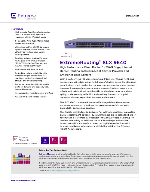
ExtremeRouting? SLX 9640
Built to Suit Your Business Needs Ext rem e Elem ent s are t he b uild ing b locks t hat allow you t o t ailor your net w ork t o your sp ecific b usiness environm ent , g oals, and ob ject ives. They enab le t he creat ion of an A ut onom ous Net w ork t hat d elivers t he p osit ive exp eriences and b usiness out com es m ost im p ort ant t o your org anizat ion.
W W W.EXTREMENETW
1
Flexib le Bo rd er Ro ut ing w it h Int ernet Scale, Ult ra-Deep Buffers,
MPLS and EVPN
The SLX 964 0 is a very p ow erful com p act d eep b uffer Int ernet b ord er rout er, p rovid ing a cost -efficient solut ion t hat is p urp ose-b uilt for t he m ost d em and ing service p rovid er and ent erp rise d at a cent ers and MA N/ WA N ap p licat ions. The rob ust syst em archit ect ure sup p ort ed by SLX-OS and a versat ile feat ure set includ ing IPv4 , IPv6, and MPLS/ VPLS w it h Carrier Et hernet 2.0 and OA M cap ab ilit ies t o p rovid e d ep loym ent flexib ilit y.
lx2160a-serdes-reconfiguration-user-说明书

1IntroductionThe device reference manual provides a list of all supported SerDes protocols.Only SerDes options that have been validated on silicon are documented in the reference manual. Custom SerDes configuration may be supported by reconfiguring the lanes for the desired settings if validated and approved by NXP. Any changes to configuration of default SerDes options require software reconfiguration.This document describes the sequence to reconfigure SerDes lanes from SGMII to USXGMII/XFI and two PCIe x2 lanes at Gen 1 or Gen 2 speeds for the LX2160A device. Subsequent reconfiguration from SFI/XFI to 10GBase-KR or USXGMII shall follow the sequence described in the LX2160A Reference Manual.2SerDes configuration requirementsThis document describes a use case requirement of four lanes of USXGMII/XFI and two PCIe x2 lanes at Gen 1 or Gen 2 speeds,shown as SerDes 1 protocol number 31 in Table 1. Protocol 31 is not one of the default SerDes options for the LX2160A, therefore,it is not documented in the LX2160A Reference Manual. However, standard MC firmware versions 10.24.1 and later add support for protocol 31.This document describes the sequence that results in the target configuration which can be summarized as:1.Start with SerDes protocol 11, which supports four lanes of SGMII on lanes F, E, B, and A, and two PCIe x2 lanes at Gen 3 speed on lanes H, G, D, and C.2.Reconfigure the SGMII lanes to USXGMII/XFI and limit the PCIe lanes to Gen 2 speed.3.Change the PLL assignment for USXGMII/XFI to PLLS since 10G Ethernet only runs on PLLS.4.Change the PLL assignment for PCIe to PLLF since it runs on 5 GHz VCO frequency so it cannot run on the same PLL as USXGMII/XFI.Table 1.SerDes 1 reconfigurationThe reconfiguration sequence assumes the following starting RCW settings:•SRDS_PRTCL_S1 = 5'b01011 to select protocol 11.Contents 1Introduction......................................12SerDes configuration requirements ........................................................13Software sequence.........................24RCWSR29 override. (65)Revision history (7)AN13022LX2160A SerDes 1 Lane Reconfiguration from 11 to 31Rev. 0 — 10/2020Application Note•SRDS_DIV_PEX_S1 = 2'b10 to configure PCIe to train up to a max rate of 5G (Gen 2).•SRDS_PLL_REF_CLK_SEL_S1 = 2'b mn, where m selects the reference clock for the PCIe lanes on PLLS and n selects the reference clock for USXGMII/XFI lanes on PLLF. Example:—m = 0 for 100 MHz PCIe reference clock—n = 1 for 161.1328125 MHz USXGMII/XFI reference clock•SRDS_PLL_PD_PLL1 = 0 and SRDS_PLL_PD_PLL2 = 0 so both PLLF and PLLS are powered up.•SRDS_REFCLKF_DIS_S1 = 0 to keep SD1_PLLF_REF_CLK enabled.•SRDS_INTRA_REF_CLK_S1 = 0 intra reference clock is not used.3Software sequenceThe reconfiguration sequence must be implemented in PBI and is shown below.1.Disable SGMII for lanes A, B, E, and F.•SD1: PCC8 (offset 0x10A0) = 0x0000_0000—SGMIIA_CFG = 0 disable SGMIIa—SGMIIB_CFG = 0 disable SGMIIb—SGMIIE_CFG = 0 disable SGMIIe—SGMIIF_CFG = 0 disable SGMIIf2.Enable XFI mode for lanes A, B, E, and F•SD1: PCCC (offset 0x10B0) = 0x9900_9900—SXGMIIA_XFI = 1 PCS operates in XFI/SFI mode—SXGMIIA_CFG = 001b enable SXGMIIa—SXGMIIB_XFI = 1 PCS operates in XFI/SFI mode—SXGMIIB_CFG = 001b enable SXGMIIb—SXGMIIE_XFI = 1 PCS operates in XFI/SFI mode—SXGMIIE_CFG = 001b enable SXGMIIe—SXGMIIF_XFI = 1 PCS operates in XFI/SFI mode—SXGMIIF_CFG = 001b enable SXGMIIf3.Assume 100 MHz reference clock for PLLF for the PCIe lanes•SD1: PLLFCR0 (offset 0x0404) = 0x0000_0000—REFCLK_SEL = 00000b for 100 MHz4.Configure 5G clock net frequency for PLLF•SD1: PLLFCR1 (offset 0x0408) = 0x9030_0008—SLOW_VCO_EN = 1 to enable the slower VCO—FRATE_SEL = 10000b for PCIe on PLLF—HI_BW_SEL = 1 to select higher PLL bandwidth—CLKD_RCAL_SLW_EN = 1 to enable resistor calibration for clock driver—RTMR_BYP = 1 to bypass retimer to clock driver and SSC phase interpolator—EX_DLY_SEL = 00b5.Set the recommended PLLF settings for PCIe 5G•SD1: PLLFCR3 (offset 0x0410) = 0x0000_3000—SSC_SEL = 00b no PLL modulation—SSC_SLP_OFF = 0000000000b for no slope offset—Bit 13 = 1—Bit 12 = 16.Set the recommended PLLF settings for PCIe 5G•SD1: PLLFCR4 (offset 0x0414) = 0x0000_0000—SSC_BIAS_BST = 000b SSC bias boost—SSC_SAW_MIN = 0000000000b SSC minimum sawtooth frequency offset—SSC_PI_BST = 00000b SSC phase interpolator Iqdiv2 boost—SSC_SAW_MAX = 0000000000b SSC maximum sawtooth frequency offset7.Assume 161.1328125 MHz reference clock for PLLS for 10GE operation•SD1: PLLSCR0 (offset 0x0504) = 0x0004_0000—REFCLK_SEL = 00100b for 161.1328125 MHz8.Configure 10.3125G clock net frequency for PLLS•SD1: PLLSCR1 (offset 0x0508) = 0x8610_0008—SLOW_VCO_EN = 1 to enable the slower VCO—FRATE_SEL = 00110b for XFI/SFI on PLLS—HI_BW_SEL = 0 to do not select higher PLL bandwidth—CLKD_RCAL_SLW_EN = 1 to enable resistor calibration for clock driver—RTMR_BYP = 1 to bypass retimer to clock driver and SSC phase interpolator—EX_DLY_SEL = 00b9.Set the recommended PLLS settings for XFI•SD1: PLLSCR3 (offset 0x0510) = 0x0000_3000—SSC_SEL = 00b no PLL modulation—SSC_SLP_OFF = 0000000000b for no slope offset—Bit 13 = 1—Bit 12 = 110.Set the recommended PLLS settings for XFI•SD1: PLLSCR4 (offset 0x0514) = 0x0000_1000—SSC_BIAS_BST = 000b SSC bias boost—SSC_SAW_MIN = 0000000000b SSC minimum sawtooth frequency offset—SSC_PI_BST = 00010b SSC phase interpolator Iqdiv2 boost—SSC_SAW_MAX = 0000000000b SSC maximum sawtooth frequency offset11.Change the PLL assignment for PCIe on the transmitter for lanes C, D, G, H from PLLS to PLLF•SD1: LNmTGCR0 (offsets 0x0A24 for lane C, 0x0B24 for lane D, 0x0E24 for lane G, 0x0F24 for lane H) = 0x0100_0200—USE_SLOW_PLL = 0 transmit uses PLLF—BY_N_RATE_SEL = 001b PCIe is half rate—CM_DLY_MATCH = 1 changes in LNmTRSTCTL[OUT_CM] are delay matched to changes in transmit data 12.Change the PLL assignment for PCIe on the receiver for lanes C, D, G, H from PLLS to PLLF•SD1: LNmRGCR0 (offsets 0x0A44 for lane C, 0x0B44 for lane D, 0x0E44 for lane G, 0x0F44 for lane H) =0x0100_0001—USE_SLOW_PLL = 0 receive uses PLLF—BY_N_RATE_SEL = 001b PCIe is half rate—PTRM_VCM_SEL = 01b Common mode is HiZ if PLLnRST[EN] or LNmRRSTCTL[EN] is negated.13.Change the protocol for lanes A, B, E, F from SGMII to XFI•SD1: LNmGCR0 (offsets 0x0800 for lane A, 0x0900 for lane B, 0x0C00 for lane E, 0x0D00 for lane F) =0x0000_0052—Bit 28 = 0 Must be 0 for all protocols—PORT_LN0_B = 0 Single-lane protocol—PROTO_SEL = 01010b for XFI—IF_WIDTH = 010b 20-bit interface width14.Set the PLL assignment for XFI on the transmitter for lanes A, B, E, F to PLLS•SD1: LNmTGCR0 (offsets 0x0824 for lane A, 0x0924 for lane B, 0x0C24 for lane E, 0x0D24 for lane F) =0x1000_0000—USE_SLOW_PLL = 1 transmit uses PLLS—BY_N_RATE_SEL = 000b 10G is full rate—CM_DLY_MATCH = 0 changes in LNmTRSTCTL[OUT_CM] are not delay matched to changes in transmit data15.Configure the transmit equalization for lanes A, B, E, F for XFI•SD1: LNmTECR0 (offsets 0x0830 for lane A, 0x0930 for lane B, 0x0C30 for lane E, 0x0D30 for lane F) =0x1080_8307—EQ_TYPE = 001b for 2-tap equalization—EQ_SGN_PREQ = 1 for positive sign for pre-cursor—EQ_PREQ = 0000b for 1.0x drive strength of transmit full swing transition bit to pre-cursor—EQ_SGN_POST1Q = 1 for positive sign for first post-cursor—EQ_POST1Q = 00011b for 1.14x drive strength of transmit full swing transition bit to first post-cursor—EQ_AMP_RED = 000111b for 0.585x overall amplitude reduction16.Set the PLL assignment for XFI on the receiver for lanes A, B, E, F to PLLS•SD1: LNmRGCR0 (offsets 0x0844 for lane A, 0x0944 for lane B, 0x0C44 for lane E, 0x0D44 for lane F) =0x1000_0000—USE_SLOW_PLL = 1 receive uses PLLS—BY_N_RATE_SEL = 000b 10G is full rate—PTRM_VCM_SEL = 00b Common mode impedance is always calibrated to SD_GND17.Set the recommended XFI settings for lanes A, B, E, F•SD1: LNmRGCR1 (offsets 0x0848 for lane A, 0x0948 for lane B, 0x0C48 for lane E, 0x0D48 for lane F) =0x1000_0000—RX_ORD_ELECIDLE = 0 Do not put into ordered idle state—Bit 28 = 1—ENTER_IDLE_FLT_SEL = 00b Bypass unexpected entrance into idle—EXIT_IDLE_FLT_SEL = 000b Force immediate exit from idle state AFTER order idle released and min time in idle—DATA_LOST_TH_SEL = 000b Disable loss of signal detection18.Disable receive equalization gain overrides for lanes A, B, E, F•SD1: LNmRECR0 (offsets 0x0850 for lane A, 0x0950 for lane B, 0x0C50 for lane E, 0x0D50 for lane F) =0x0000_000019.Set the recommended the receive equalization for XFI for lanes A, B, E, F•SD1: LNmRECR2 (offsets 0x0858 for lane A, 0x0958 for lane B, 0x0C58 for lane E, 0x0D58 for lane F) =0x8100_0020—Bit 31 = 1—EQ_BLW_SEL = 01b baseline wander for 10G—Bits 5:4 = 10bThe PBI sequence is shown below:.pbiwrite 0x01EA10A0,0x00000000write 0x01EA10B0,0x99009900write 0x01EA0404,0x00000000write 0x01EA0408,0x90300008write 0x01EA0410,0x00003000write 0x01EA0414,0x00000000write 0x01EA0504,0x00040000write 0x01EA0508,0x86100008write 0x01EA0510,0x00003000write 0x01EA0514,0x00001000write 0x01EA0A24,0x01000200write 0x01EA0A44,0x01000001write 0x01EA0B24,0x01000200write 0x01EA0B44,0x01000001write 0x01EA0E24,0x01000200write 0x01EA0E44,0x01000001write 0x01EA0F24,0x01000200write 0x01EA0F44,0x01000001write 0x01EA0800,0x00000052write 0x01EA0900,0x00000052write 0x01EA0C00,0x00000052write 0x01EA0D00,0x00000052write 0x01EA0824,0x10000000write 0x01EA0924,0x10000000write 0x01EA0C24,0x10000000RCWSR29 override write 0x01EA0D24,0x10000000write 0x01EA0830,0x10808307write 0x01EA0930,0x10808307write 0x01EA0C30,0x10808307write 0x01EA0D30,0x10808307write 0x01EA0844,0x10000000write 0x01EA0944,0x10000000write 0x01EA0C44,0x10000000write 0x01EA0D44,0x10000000write 0x01EA0848,0x10000000write 0x01EA0948,0x10000000write 0x01EA0C48,0x10000000write 0x01EA0D48,0x10000000write 0x01EA0850,0x00000000write 0x01EA0950,0x00000000write 0x01EA0C50,0x00000000write 0x01EA0D50,0x00000000write 0x01EA0858,0x81000020write 0x01EA0958,0x81000020write 0x01EA0C58,0x81000020write 0x01EA0D58,0x81000020.end4RCWSR29 overrideThe Reset Configuration Word Status Registers (RCWSR1:RCWSR32) are written with the RCW information that are read from flash memory by the device at power-on-reset. The RCWSR register values are read-only after exiting reset.Software (U-boot) reads the selected SerDes protocol from RCWSR29. It looks at the SerDes configuration table to find the entry for protocol 31 and its corresponding interfaces. In order for software (U-boot) to read the updated SerDes 1 protocol value of 31, the following steps must be performed:1.Add an entry for SerDes 1 protocol 31 in the SerDes configuration table in U-boot2.Override the RCWSR29 with the updated SerDes 1 protocol value of 31•Write to address 0x7_00100170 the new protocol SRDS_PRTCL_S1 = 31.•The SerDes 2 and SerDes 3 configuration fields should remain unchanged.•Note: The RCWSR29 cannot be updated from the PBI phase. The update must be done in the initial stages of the the board-specific U-boot code so that the correct SerDes protocol is read as U-boot continues execution.Table 2.Address 0x7_0010017031302928272625242322212019181716 SRDS_PRTCL_S3SRDS_PRTCL_S2SRDS_PRTCL_S1SRDS_REFCLKF_DIS_S11514131211109876543210Table continues on the next page...Table 2.Address 0x7_00100170 (continued)ReservedSRDS_PLL_P D_PLL6SRDS_PLL_P D_PLL5SRDS_PLL_P D_PLL4SRDS_PLL_P D_PLL3SRDS_PLL_P D_PLL2SRDS_PLL_P D_PLL1Any support, information, and technology (“Materials”) provided by NXP are provided AS IS, without any warranty express or implied, and NXP disclaims all direct and indirect liability and damages in connection with the Material to the maximum extent permitted by the applicable law. NXP accepts no liability for any assistance with applicationsor product design. Materials may only be used in connection with NXP products. Any feedback provided to NXP regarding the Materials may be used by NXP without restriction.5Revision historyThe table below summarizes the revisions to this document.Table 3.Revision history Revision historyHow To Reach Us Home Page: Web Support: /support Information in this document is provided solely to enable system and software implementersto use NXP products. There are no express or implied copyright licenses granted hereunderto design or fabricate any integrated circuits based on the information in this document. NXP reserves the right to make changes without further notice to any products herein.NXP makes no warranty, representation, or guarantee regarding the suitability of its products for any particular purpose, nor does NXP assume any liability arising out of the applicationor use of any product or circuit, and specifically disclaims any and all liability, includingwithout limitation consequential or incidental damages. “Typical” parameters that may be provided in NXP data sheets and/or specifications can and do vary in different applications, and actual performance may vary over time. All operating parameters, including “typicals,”must be validated for each customer application by customer's technical experts. NXP does not convey any license under its patent rights nor the rights of others. NXP sells products pursuant to standard terms and conditions of sale, which can be found at the following address: /SalesTermsandConditions.Security — Customer understands that all NXP products may be subject to unidentifiedor documented vulnerabilities. Customer is responsible for the design and operation of its applications and products throughout their lifecycles to reduce the effect of these vulnerabilities on customer’s applications and products. Customer’s responsibility also extends to other open and/or proprietary technologies supported by NXP products for use in customer’s applications. NXP accepts no liability for any vulnerability. Customer should regularly check security updates from NXP and follow up appropriately. Customer shall select products with security features that best meet rules, regulations, and standards of the intended application and make the ultimate design decisions regarding its products and is solely responsible for compliance with all legal, regulatory, and security related requirements concerning its products, regardless of any information or support that may be provided by NXP. NXP has a Product Security Incident ResponseTeam(PSIRT)(************************)thatmanagestheinvestigation, reporting, and solution release to security vulnerabilities of NXP products.NXP, the NXP logo, Freescale, the Freescale logo, CodeWarrior, Layerscape, and QorIQ are trademarks of NXP B.V. All other product or service names are the property of their respective owners. Arm and Cortex are registered trademarks of Arm Limited (or its subsidiaries) in the US and/or elsewhere. The related technology may be protected by any or all of patents, copyrights, designs and trade secrets. All rights reserved. The Power Architecture and word marks and the Power and logos and related marks are trademarks and service marks licensed by .© NXP B.V. 2020.All rights reserved.For more information, please visit: Forsalesofficeaddresses,pleasesendanemailto:**********************Date of release: 10/2020Document identifier: AN13022。
rfc6238标准

rfc6238标准RFC 6238是一项具体指定了时间基础上的一次性密码(TOTP)算法的标准。
该算法以时间为基础,通过使用哈希函数生成一次性密码,以提高身份验证的安全性。
以下是与RFC 6238相关的参考内容:1. TOTP算法的定义:- TOTP算法是基于RFC 6238的一次性密码生成算法,该算法使用时间窗口以及预共享密钥生成一次性密码。
TOTP算法广泛应用于多因素身份验证中。
2. 时间同步性要求:- RFC 6238指定了一种时间同步性要求,要求使用TOTP算法的设备和验证服务器在时间上保持一致。
这确保了一次性密码的生成是基于准确的时间。
3. 哈希函数的应用:- RFC 6238指定了一种基于哈希函数的一次性密码生成方法。
常见的哈希函数包括SHA-1、SHA-256等。
哈希函数用于将时间和预共享密钥生成一次性密码的散列值。
4. 预共享密钥的生成与管理:- RFC 6238强调了预共享密钥的安全性和管理。
预共享密钥用于生成一次性密码,必须保持机密,并且需要在生成一次性密码的设备和验证服务器之间进行安全传输及存储。
5. 时间窗口的定义与使用:- RFC 6238定义了时间窗口的概念,用于控制一次性密码的有效期。
时间窗口指定了在某一个时间点前后允许认证的一次性密码数量。
6. 安全性考虑:- RFC 6238特别强调了一次性密码算法的安全性考虑。
例如,保护设备和服务器上的预共享密钥的机密性,防范重放攻击等。
此外,该标准还对一次性密码生成和验证过程中的潜在安全漏洞提出了一些建议。
7. 应用场景的拓展:- RFC 6238指定的TOTP算法可以应用于多种身份验证场景,例如互联网银行、VPN访问、云服务等。
该算法提供了一种简单且安全的方式,以提供额外的身份验证保护。
8. 其他相关标准和扩展:- RFC 6238不是独立的标准,它与其他相关身份验证标准和扩展相结合使用,以提供更全面的身份验证解决方案。
这些标准包括RFC 4226(HOTP:基于哈希的一次性密码)和RFC 6287(HOTP扩展)等。
核电厂软件开发标准

核电厂的软件开发需要遵循一系列国际标准和规范,以确保软件的安全性、可靠性和有效性。
以下是一些重要的核电厂软件开发标准:
1. IEC 60880:这是关于核电站安全系统用计算机软件的标准,包括对安全重要的仪器和控制系统形成A类功能的计算机系统的软件问题。
2. EN 62138:这是一个欧洲标准,规定了核电站中,对安全性重要的仪表与控制、计算机系统B类或C功能软件的运行要求。
3. IEEE 1012:这是关于软件验证和确认的标准,用于确保核电厂软件的安全性和可靠性。
4. ISO 26262:这是一个关于道路车辆安全的国际标准,但也可应用于核电厂的软件开发,特别是涉及到安全相关的功能。
5. CSA N26250:这是加拿大核安全委员会发布的关于核电厂软件安全的指南,其中包括对软件开发和维护的要求。
这些标准通常会要求软件开发人员遵循严格的安全实践,包括对软件的验证和确认、安全分析和风险评估、安全审查和测试等。
同时,这些标准也会要求软件开发人员与核电厂运营商和监管机构密切合作,以确保软件在整个生命周期内都满足所有安全要求。
rfc2782.A DNS RR for specifying the location of services (DNS SRV)

Network Working Group A. Gulbrandsen Request for Comments: 2782 Troll Technologies Obsoletes: 2052 P. Vixie Category: Standards Track Internet Software Consortium L. Esibov Microsoft Corp. February 2000 A DNS RR for specifying the location of services (DNS SRV)Status of this MemoThis document specifies an Internet standards track protocol for the Internet community, and requests discussion and suggestions forimprovements. Please refer to the current edition of the "InternetOfficial Protocol Standards" (STD 1) for the standardization stateand status of this protocol. Distribution of this memo is unlimited.Copyright NoticeCopyright (C) The Internet Society (2000). All Rights Reserved.AbstractThis document describes a DNS RR which specifies the location of the server(s) for a specific protocol and domain.Overview and rationaleCurrently, one must either know the exact address of a server tocontact it, or broadcast a question.The SRV RR allows administrators to use several servers for a single domain, to move services from host to host with little fuss, and todesignate some hosts as primary servers for a service and others asbackups.Clients ask for a specific service/protocol for a specific domain(the word domain is used here in the strict RFC 1034 sense), and get back the names of any available servers.Note that where this document refers to "address records", it means A RR’s, AAAA RR’s, or their most modern equivalent.Gulbrandsen, et al. Standards Track [Page 1]DefinitionsThe key words "MUST", "MUST NOT", "SHOULD", "SHOULD NOT" and "MAY"used in this document are to be interpreted as specified in [BCP 14]. Other terms used in this document are defined in the DNSspecification, RFC 1034.Applicability StatementIn general, it is expected that SRV records will be used by clientsfor applications where the relevant protocol specification indicates that clients should use the SRV record. Such specification MUSTdefine the symbolic name to be used in the Service field of the SRVrecord as described below. It also MUST include securityconsiderations. Service SRV records SHOULD NOT be used in the absence of such specification.Introductory exampleIf a SRV-cognizant LDAP client wants to discover a LDAP server thatsupports TCP protocol and provides LDAP service for the domain., it does a lookup of_ldap._as described in [ARM]. The example zone file near the end of thismemo contains answering RRs for an SRV query.Note: LDAP is chosen as an example for illustrative purposes only,and the LDAP examples used in this document should not be considered a definitive statement on the recommended way for LDAP to use SRVrecords. As described in the earlier applicability section, consultthe appropriate LDAP documents for the recommended procedures.The format of the SRV RRHere is the format of the SRV RR, whose DNS type code is 33:_Service._ TTL Class SRV Priority Weight Port Target(There is an example near the end of this document.)ServiceThe symbolic name of the desired service, as defined in Assigned Numbers [STD 2] or locally. An underscore (_) is prepended tothe service identifier to avoid collisions with DNS labels that occur in nature.Gulbrandsen, et al. Standards Track [Page 2]Some widely used services, notably POP, don’t have a singleuniversal name. If Assigned Numbers names the serviceindicated, that name is the only name which is legal for SRVlookups. The Service is case insensitive.ProtoThe symbolic name of the desired protocol, with an underscore(_) prepended to prevent collisions with DNS labels that occurin nature. _TCP and _UDP are at present the most useful values for this field, though any name defined by Assigned Numbers orlocally may be used (as for Service). The Proto is caseinsensitive.NameThe domain this RR refers to. The SRV RR is unique in that the name one searches for is not this name; the example near the end shows this clearly.TTLStandard DNS meaning [RFC 1035].ClassStandard DNS meaning [RFC 1035]. SRV records occur in the INClass.PriorityThe priority of this target host. A client MUST attempt tocontact the target host with the lowest-numbered priority it can reach; target hosts with the same priority SHOULD be tried in an order defined by the weight field. The range is 0-65535. This is a 16 bit unsigned integer in network byte order.WeightA server selection mechanism. The weight field specifies arelative weight for entries with the same priority. Largerweights SHOULD be given a proportionately higher probability of being selected. The range of this number is 0-65535. This is a 16 bit unsigned integer in network byte order. Domainadministrators SHOULD use Weight 0 when there isn’t any serverselection to do, to make the RR easier to read for humans (less noisy). In the presence of records containing weights greaterthan 0, records with weight 0 should have a very small chance of being selected.In the absence of a protocol whose specification calls for theuse of other weighting information, a client arranges the SRVRRs of the same Priority in the order in which target hosts, Gulbrandsen, et al. Standards Track [Page 3]specified by the SRV RRs, will be contacted. The followingalgorithm SHOULD be used to order the SRV RRs of the samepriority:To select a target to be contacted next, arrange all SRV RRs(that have not been ordered yet) in any order, except that allthose with weight 0 are placed at the beginning of the list.Compute the sum of the weights of those RRs, and with each RRassociate the running sum in the selected order. Then choose auniform random number between 0 and the sum computed(inclusive), and select the RR whose running sum value is thefirst in the selected order which is greater than or equal tothe random number selected. The target host specified in theselected SRV RR is the next one to be contacted by the client.Remove this SRV RR from the set of the unordered SRV RRs andapply the described algorithm to the unordered SRV RRs to select the next target host. Continue the ordering process until there are no unordered SRV RRs. This process is repeated for eachPriority.PortThe port on this target host of this service. The range is 0-65535. This is a 16 bit unsigned integer in network byte order. This is often as specified in Assigned Numbers but need not be. TargetThe domain name of the target host. There MUST be one or moreaddress records for this name, the name MUST NOT be an alias (in the sense of RFC 1034 or RFC 2181). Implementors are urged, but not required, to return the address record(s) in the Additional Data section. Unless and until permitted by future standardsaction, name compression is not to be used for this field.A Target of "." means that the service is decidedly notavailable at this domain.Domain administrator adviceExpecting everyone to update their client applications when the first server publishes a SRV RR is futile (even if desirable). ThereforeSRV would have to coexist with address record lookups for existingprotocols, and DNS administrators should try to provide addressrecords to support old clients:- Where the services for a single domain are spread over severalhosts, it seems advisable to have a list of address records atthe same DNS node as the SRV RR, listing reasonable (if perhaps Gulbrandsen, et al. Standards Track [Page 4]suboptimal) fallback hosts for Telnet, NNTP and other protocols likely to be used with this name. Note that some programs only try the first address they get back from e.g. gethostbyname(),and we don’t know how widespread this behavior is.- Where one service is provided by several hosts, one can eitherprovide address records for all the hosts (in which case theround-robin mechanism, where available, will share the loadequally) or just for one (presumably the fastest).- If a host is intended to provide a service only when the mainserver(s) is/are down, it probably shouldn’t be listed inaddress records.- Hosts that are referenced by backup address records must use the port number specified in Assigned Numbers for the service.- Designers of future protocols for which "secondary servers" isnot useful (or meaningful) may choose to not use SRV’s supportfor secondary servers. Clients for such protocols may use orignore SRV RRs with Priority higher than the RR with the lowest Priority for a domain.Currently there’s a practical limit of 512 bytes for DNS replies.Until all resolvers can handle larger responses, domainadministrators are strongly advised to keep their SRV replies below512 bytes.All round numbers, wrote Dr. Johnson, are false, and these numbersare very round: A reply packet has a 30-byte overhead plus the nameof the service ("_ldap._" for instance); each SRV RRadds 20 bytes plus the name of the target host; each NS RR in the NS section is 15 bytes plus the name of the name server host; andfinally each A RR in the additional data section is 20 bytes or so,and there are A’s for each SRV and NS RR mentioned in the answer.This size estimate is extremely crude, but shouldn’t underestimatethe actual answer size by much. If an answer may be close to thelimit, using a DNS query tool (e.g. "dig") to look at the actualanswer is a good idea.The "Weight" fieldWeight, the server selection field, is not quite satisfactory, butthe actual load on typical servers changes much too quickly to bekept around in DNS caches. It seems to the authors that offeringadministrators a way to say "this machine is three times as fast asthat one" is the best that can practically be done.Gulbrandsen, et al. Standards Track [Page 5]The only way the authors can see of getting a "better" load figure is asking a separate server when the client selects a server andcontacts it. For short-lived services an extra step in theconnection establishment seems too expensive, and for long-livedservices, the load figure may well be thrown off a minute after theconnection is established when someone else starts or finishes aheavy job.Note: There are currently various experiments at providing relativenetwork proximity estimation, available bandwidth estimation, andsimilar services. Use of the SRV record with such facilities, and in particular the interpretation of the Weight field when thesefacilities are used, is for further study. Weight is only intendedfor static, not dynamic, server selection. Using SRV weight fordynamic server selection would require assigning unreasonably shortTTLs to the SRV RRs, which would limit the usefulness of the DNScaching mechanism, thus increasing overall network load anddecreasing overall reliability. Server selection via SRV is onlyintended to express static information such as "this server has afaster CPU than that one" or "this server has a much better networkconnection than that one".The Port numberCurrently, the translation from service name to port number happensat the client, often using a file such as /etc/services.Moving this information to the DNS makes it less necessary to update these files on every single computer of the net every time a newservice is added, and makes it possible to move standard services out of the "root-only" port range on unix.Usage rulesA SRV-cognizant client SHOULD use this procedure to locate a list of servers and connect to the preferred one:Do a lookup for QNAME=_service._protocol.target, QCLASS=IN,QTYPE=SRV.If the reply is NOERROR, ANCOUNT>0 and there is at least oneSRV RR which specifies the requested Service and Protocol inthe reply:If there is precisely one SRV RR, and its Target is "."(the root domain), abort.Gulbrandsen, et al. Standards Track [Page 6]Else, for all such RR’s, build a list of (Priority, Weight, Target) tuplesSort the list by priority (lowest number first)Create a new empty listFor each distinct priority levelWhile there are still elements left at this prioritylevelSelect an element as specified above, in thedescription of Weight in "The format of the SRVRR" Section, and move it to the tail of the newlistFor each element in the new listquery the DNS for address records for the Target oruse any such records found in the Additional Datasection of the earlier SRV response.for each address record found, try to connect to the(protocol, address, service).elseDo a lookup for QNAME=target, QCLASS=IN, QTYPE=Afor each address record found, try to connect to the(protocol, address, service)Notes:- Port numbers SHOULD NOT be used in place of the symbolic serviceor protocol names (for the same reason why variant names cannotbe allowed: Applications would have to do two or more lookups).- If a truncated response comes back from an SRV query, the rulesdescribed in [RFC 2181] shall apply.- A client MUST parse all of the RR’s in the reply.- If the Additional Data section doesn’t contain address recordsfor all the SRV RR’s and the client may want to connect to thetarget host(s) involved, the client MUST look up the addressrecord(s). (This happens quite often when the address recordhas shorter TTL than the SRV or NS RR’s.)Gulbrandsen, et al. Standards Track [Page 7]- Future protocols could be designed to use SRV RR lookups as themeans by which clients locate their servers.Fictional exampleThis example uses fictional service "foobar" as an aid inunderstanding SRV records. If ever service "foobar" is implemented,it is not intended that it will necessarily use SRV records. This is (part of) the zone file for , a still-unused domain:$ORIGIN .@ SOA . . (1995032001 3600 3600 604800 86400 )NS .NS .NS .; foobar - use old-slow-box or new-fast-box if either is; available, make three quarters of the logins go to; new-fast-box._foobar._tcp SRV 0 1 9 .SRV 0 3 9 .; if neither old-slow-box or new-fast-box is up, switch to; using the sysdmin’s box and the serverSRV 1 0 9 .SRV 1 0 9 .server A 172.30.79.10old-slow-box A 172.30.79.11sysadmins-box A 172.30.79.12new-fast-box A 172.30.79.13; NO other services are supported*._tcp SRV 0 0 0 .*._udp SRV 0 0 0 .Gulbrandsen, et al. Standards Track [Page 8]In this example, a client of the "foobar" service in the"." domain needs an SRV lookup of"_foobar._." and possibly A lookups of "new-fast-." and/or the other hosts named. The size of the SRV reply is approximately 365 bytes:30 bytes general overhead20 bytes for the query string, "_foobar._."130 bytes for 4 SRV RR’s, 20 bytes each plus the lengths of "new- fast-box", "old-slow-box", "server" and "sysadmins-box" -"" in the query section is quoted here and doesn’tneed to be counted again.75 bytes for 3 NS RRs, 15 bytes each plus the lengths of "server", "." and "ns2" - again, "." is quoted and only needs to be counted once.120 bytes for the 6 address records (assuming IPv4 only) mentioned by the SRV and NS RR’s.IANA ConsiderationsThe IANA has assigned RR type value 33 to the SRV RR. No other IANA services are required by this document.Changes from RFC 2052This document obsoletes RFC 2052. The major change from thatprevious, experimental, version of this specification is that now the protocol and service labels are prepended with an underscore, tolower the probability of an accidental clash with a similar name used for unrelated purposes. Aside from that, changes are only intendedto increase the clarity and completeness of the document. Thisdocument especially clarifies the use of the Weight field of the SRV records.Security ConsiderationsThe authors believe this RR to not cause any new security problems.Some problems become more visible, though.- The ability to specify ports on a fine-grained basis obviouslychanges how a router can filter packets. It becomes impossibleto block internal clients from accessing specific externalservices, slightly harder to block internal users from runningunauthorized services, and more important for the routeroperations and DNS operations personnel to cooperate.- There is no way a site can keep its hosts from being referencedas servers. This could lead to denial of service.Gulbrandsen, et al. Standards Track [Page 9]- With SRV, DNS spoofers can supply false port numbers, as well ashost names and addresses. Because this vulnerability existsalready, with names and addresses, this is not a newvulnerability, merely a slightly extended one, with littlepractical effect.ReferencesSTD 2: Reynolds, J., and J. Postel, "Assigned Numbers", STD 2, RFC 1700, October 1994.RFC 1034: Mockapetris, P., "Domain names - concepts and facilities", STD 13, RFC 1034, November 1987.RFC 1035: Mockapetris, P., "Domain names - Implementation andSpecification", STD 13, RFC 1035, November 1987.RFC 974: Partridge, C., "Mail routing and the domain system", STD14, RFC 974, January 1986.BCP 14: Bradner, S., "Key words for use in RFCs to IndicateRequirement Levels", BCP 14, RFC 2119, March 1997.RFC 2181: Elz, R. and R. Bush, "Clarifications to the DNSSpecification", RFC 2181, July 1997.RFC 2219: Hamilton, M. and R. Wright, "Use of DNS Aliases for Network Services", BCP 17, RFC 2219, October 1997.BCP 14: Bradner, S., "Key words for use in RFCs to IndicateRequirement Levels", BCP 14, RFC 2119, March 1997.ARM: Armijo, M., Esibov, L. and P. Leach, "Discovering LDAPServices with DNS", Work in Progress.KDC-DNS: Hornstein, K. and J. Altman, "Distributing Kerberos KDC and Realm Information with DNS", Work in Progress.Gulbrandsen, et al. Standards Track [Page 10]AcknowledgementsThe algorithm used to select from the weighted SRV RRs of equalpriority is adapted from one supplied by Dan Bernstein.Authors’ AddressesArnt GulbrandsenTroll TechWaldemar Thranes gate 98BN-0175 Oslo, NorwayFax: +47 22806380Phone: +47 22806390EMail: arnt@troll.noPaul VixieInternet Software Consortium950 Charter StreetRedwood City, CA 94063Phone: +1 650 779 7001Levon EsibovMicrosoft CorporationOne Microsoft WayRedmond, WA 98052EMail: levone@Gulbrandsen, et al. Standards Track [Page 11]Full Copyright StatementCopyright (C) The Internet Society (2000). All Rights Reserved.This document and translations of it may be copied and furnished toothers, and derivative works that comment on or otherwise explain it or assist in its implementation may be prepared, copied, publishedand distributed, in whole or in part, without restriction of anykind, provided that the above copyright notice and this paragraph are included on all such copies and derivative works. However, thisdocument itself may not be modified in any way, such as by removingthe copyright notice or references to the Internet Society or otherInternet organizations, except as needed for the purpose ofdeveloping Internet standards in which case the procedures forcopyrights defined in the Internet Standards process must befollowed, or as required to translate it into languages other thanEnglish.The limited permissions granted above are perpetual and will not berevoked by the Internet Society or its successors or assigns.This document and the information contained herein is provided on an "AS IS" basis and THE INTERNET SOCIETY AND THE INTERNET ENGINEERINGTASK FORCE DISCLAIMS ALL WARRANTIES, EXPRESS OR IMPLIED, INCLUDINGBUT NOT LIMITED TO ANY WARRANTY THAT THE USE OF THE INFORMATIONHEREIN WILL NOT INFRINGE ANY RIGHTS OR ANY IMPLIED WARRANTIES OFMERCHANTABILITY OR FITNESS FOR A PARTICULAR PURPOSE.AcknowledgementFunding for the RFC Editor function is currently provided by theInternet Society.Gulbrandsen, et al. Standards Track [Page 12]。
- 1、下载文档前请自行甄别文档内容的完整性,平台不提供额外的编辑、内容补充、找答案等附加服务。
- 2、"仅部分预览"的文档,不可在线预览部分如存在完整性等问题,可反馈申请退款(可完整预览的文档不适用该条件!)。
- 3、如文档侵犯您的权益,请联系客服反馈,我们会尽快为您处理(人工客服工作时间:9:00-18:30)。
Network Working Group E. Crawley, Editor Request for Comments: 2382 Argon Networks Category: Informational L. Berger Fore Systems S. Berson ISI F. Baker Cisco Systems M. Borden Bay Networks J. Krawczyk ArrowPoint Communications August 1998 A Framework for Integrated Services and RSVP over ATMStatus of this MemoThis memo provides information for the Internet community. It doesnot specify an Internet standard of any kind. Distribution of thismemo is unlimited.Copyright NoticeCopyright (C) The Internet Society (1998). All Rights Reserved. AbstractThis document outlines the issues and framework related to providing IP Integrated Services with RSVP over ATM. It provides an overallapproach to the problem(s) and related issues. These issues andproblems are to be addressed in further documents from the ISATMsubgroup of the ISSLL working group.1. IntroductionThe Internet currently has one class of service normally referred to as "best effort." This service is typified by first-come, first-serve scheduling at each hop in the network. Best effort service has worked well for electronic mail, World Wide Web (WWW) access, filetransfer (e.g. ftp), etc. For real-time traffic such as voice andvideo, the current Internet has performed well only across unloadedportions of the network. In order to provide quality real-timetraffic, new classes of service and a QoS signalling protocol are Crawley, et. al. Informational [Page 1]being introduced in the Internet [1,6,7], while retaining theexisting best effort service. The QoS signalling protocol is RSVP[1], the Resource ReSerVation Protocol and the service modelsOne of the important features of ATM technology is the ability torequest a point-to-point Virtual Circuit (VC) with a specifiedQuality of Service (QoS). An additional feature of ATM technology is the ability to request point-to-multipoint VCs with a specified QoS. Point-to-multipoint VCs allows leaf nodes to be added and removedfrom the VC dynamically and so provides a mechanism for supporting IP multicast. It is only natural that RSVP and the Internet IntegratedServices (IIS) model would like to utilize the QoS properties of any underlying link layer including ATM, and this memo concentrates onATM.Classical IP over ATM [10] has solved part of this problem,supporting IP unicast best effort traffic over ATM. Classical IPover ATM is based on a Logical IP Subnetwork (LIS), which is aseparately administered IP subnetwork. Hosts within an LIScommunicate using the ATM network, while hosts from different subnets communicate only by going through an IP router (even though it may be possible to open a direct VC between the two hosts over the ATMnetwork). Classical IP over ATM provides an Address ResolutionProtocol (ATMARP) for ATM edge devices to resolve IP addresses tonative ATM addresses. For any pair of IP/ATM edge devices (i.e.hosts or routers), a single VC is created on demand and shared forall traffic between the two devices. A second part of the RSVP andIIS over ATM problem, IP multicast, is being solved with MARS [5],the Multicast Address Resolution Server.MARS compliments ATMARP by allowing an IP address to resolve into alist of native ATM addresses, rather than just a single address.The ATM Forum’s LAN Emulation (LANE) [17, 20] and Multiprotocol Over ATM (MPOA) [18] also address the support of IP best effort trafficover ATM through similar means.A key remaining issue for IP in an ATM environment is the integration of RSVP signalling and ATM signalling in support of the InternetIntegrated Services (IIS) model. There are two main areas involvedin supporting the IIS model, QoS translation and VC management. QoStranslation concerns mapping a QoS from the IIS model to a proper ATM QoS, while VC management concentrates on how many VCs are needed and which traffic flows are routed over which VCs.Crawley, et. al. Informational [Page 2]1.1 Structure and Related DocumentsThis document provides a guide to the issues for IIS over ATM. It is intended to frame the problems that are to be addressed in furtherdocuments. In this document, the modes and models for RSVP operation over ATM will be discussed followed by a discussion of management of ATM VCs for RSVP data and control. Lastly, the topic ofencapsulations will be discussed in relation to the models presented. This document is part of a group of documents from the ISATM subgroup of the ISSLL working group related to the operation of IntServ andRSVP over ATM. [14] discusses the mapping of the IntServ models for Controlled Load and Guaranteed Service to ATM. [15 and 16] discussdetailed implementation requirements and guidelines for RSVP overATM, respectively. While these documents may not address all theissues raised in this document, they should provide enoughinformation for development of solutions for IntServ and RSVP overATM.1.2 TermsSeveral term used in this document are used in many contexts, oftenwith different meaning. These terms are used in this document withthe following meaning:- Sender is used in this document to mean the ingress point to theATM network or "cloud".- Receiver is used in this document to refer to the egress point from the ATM network or "cloud".- Reservation is used in this document to refer to an RSVP initiated request for resources. RSVP initiates requests for resources based on RESV message processing. RESV messages that simply refresh state do not trigger resource requests. Resource requests may be madebased on RSVP sessions and RSVP reservation styles. RSVP stylesdictate whether the reserved resources are used by one sender orshared by multiple senders. See [1] for details of each. Each newrequest is referred to in this document as an RSVP reservation, or simply reservation.- Flow is used to refer to the data traffic associated with aparticular reservation. The specific meaning of flow is RSVP style dependent. For shared style reservations, there is one flow persession. For distinct style reservations, there is one flow persender (per session).2. Issues Regarding the Operation of RSVP and IntServ over ATMThe issues related to RSVP and IntServ over ATM fall into severalgeneral classes:Crawley, et. al. Informational [Page 3]- How to make RSVP run over ATM now and in the future- When to set up a virtual circuit (VC) for a specific Quality ofService (QoS) related to RSVP- How to map the IntServ models to ATM QoS models- How to know that an ATM network is providing the QoS necessary for a flow- How to handle the many-to-many connectionless features of IPmulticast and RSVP in the one-to-many connection-oriented world of ATM2.1 Modes/Models for RSVP and IntServ over ATM[3] Discusses several different models for running IP over ATMnetworks. [17, 18, and 20] also provide models for IP in ATMenvironments. Any one of these models would work as long as the RSVP control packets (IP protocol 46) and data packets can follow the same IP path through the network. It is important that the RSVP PATHmessages follow the same IP path as the data such that appropriatePATH state may be installed in the routers along the path. For anATM subnetwork, this means the ingress and egress points must be the same in both directions for the RSVP control and data messages. Note that the RSVP protocol does not require symmetric routing. The PATH state installed by RSVP allows the RESV messages to "retrace" thehops that the PATH message crossed. Within each of the models for IP over ATM, there are decisions about using different types of datadistribution in ATM as well as different connection initiation. The following sections look at some of the different ways QoS connections can be set up for RSVP.2.1.1 UNI3.x and4.0In the User Network Interface (UNI) 3.0 and 3.1 specifications [8,9] and 4.0 specification, both permanent and switched virtual circuits(PVC and SVC) may be established with a specified service category(CBR, VBR, and UBR for UNI 3.x and VBR-rt and ABR for 4.0) andspecific traffic descriptors in point-to-point and point-to-multipoint configurations. Additional QoS parameters are notavailable in UNI 3.x and those that are available are vendor-specific. Consequently, the level of QoS control available instandard UNI 3.x networks is somewhat limited. However, using these building blocks, it is possible to use RSVP and the IntServ models.ATM 4.0 with the Traffic Management (TM) 4.0 specification [21]allows much greater control of QoS. [14] provides the details ofmapping the IntServ models to UNI 3.x and 4.0 service categories and traffic parameters.Crawley, et. al. Informational [Page 4]2.1.1.1 Permanent Virtual Circuits (PVCs)PVCs emulate dedicated point-to-point lines in a network, so theoperation of RSVP can be identical to the operation over any point-to-point network. The QoS of the PVC must be consistent andequivalent to the type of traffic and service model used. Thedevices on either end of the PVC have to provide traffic controlservices in order to multiplex multiple flows over the same PVC.With PVCs, there is no issue of when or how long it takes to set upVCs, since they are made in advance but the resources of the PVC are limited to what has been pre-allocated. PVCs that are not fullyutilized can tie up ATM network resources that could be used forSVCs.An additional issue for using PVCs is one of network engineering.Frequently, multiple PVCs are set up such that if all the PVCs wererunning at full capacity, the link would be over-subscribed. Thisfrequently used "statistical multiplexing gain" makes providing IISover PVCs very difficult and unreliable. Any application of IIS over PVCs has to be assured that the PVCs are able to receive all therequested QoS.2.1.1.2 Switched Virtual Circuits (SVCs)SVCs allow paths in the ATM network to be set up "on demand". Thisallows flexibility in the use of RSVP over ATM along with somecomplexity. Parallel VCs can be set up to allow best-effort andbetter service class paths through the network, as shown in Figure 1. The cost and time to set up SVCs can impact their use. For example, it may be better to initially route QoS traffic over existing VCsuntil a SVC with the desired QoS can be set up for the flow. Scaling issues can come into play if a single RSVP flow is used per VC, aswill be discussed in Section 4.3.1.1. The number of VCs in any ATMdevice may also be limited so the number of RSVP flows that can besupported by a device can be strictly limited to the number of VCsavailable, if we assume one flow per VC. Section 4 discusses thetopic of VC management for RSVP in greater detail.Crawley, et. al. Informational [Page 5]Data Flow ==========>+-----+| | --------------> +----+| Src | --------------> | R1 || *| --------------> +----++-----+ QoS VCs/\||VC ||InitiatorFigure 1: Data Flow VC InitiationWhile RSVP is receiver oriented, ATM is sender oriented. This might seem like a problem but the sender or ingress point receives RSVPRESV messages and can determine whether a new VC has to be set up to the destination or egress point.2.1.1.3 Point to MultiPointIn order to provide QoS for IP multicast, an important feature ofRSVP, data flows must be distributed to multiple destinations from a given source. Point-to-multipoint VCs provide such a mechanism. It is important to map the actions of IP multicasting and RSVP (e.g.IGMP JOIN/LEAVE and RSVP RESV/RESV TEAR) to add party and drop party functions for ATM. Point-to-multipoint VCs as defined in UNI 3.x and UNI 4.0 have a single service class for all destinations. This iscontrary to the RSVP "heterogeneous receiver" concept. It ispossible to set up a different VC to each receiver requesting adifferent QoS, as shown in Figure 2. This again can run into scaling and resource problems when managing multiple VCs on the sameinterface to different destinations.Crawley, et. al. Informational [Page 6]+----++------> | R1 || +----+|| +----++-----+ -----+ +--> | R2 || | ---------+ +----+ Receiver Request Types:| Src | ----> QoS 1 and QoS 2| | .........+ +----+ ....> Best-Effort+-----+ .....+ +..> | R3 |: +----+/\ :|| : +----+|| +......> | R4 ||| +----+SingleIP MulticastGroupFigure 2: Types of Multicast ReceiversRSVP sends messages both up and down the multicast distribution tree. In the case of a large ATM cloud, this could result in a RSVP message implosion at an ATM ingress point with many receivers.ATM 4.0 expands on the point-to-multipoint VCs by adding a LeafInitiated Join (LIJ) capability. LIJ allows an ATM end point to join into an existing point-to-multipoint VC without necessarilycontacting the source of the VC. This can reduce the burden on theATM source point for setting up new branches and more closely matches the receiver-based model of RSVP and IP multicast. However, many of the same scaling issues exist and the new branches added to a point- to-multipoint VC must use the same QoS as existing branches.2.1.1.4 Multicast ServersIP-over-ATM has the concept of a multicast server or reflector thatcan accept cells from multiple senders and send them via a point-to- multipoint VC to a set of receivers. This moves the VC scalingissues noted previously for point-to-multipoint VCs to the multicast server. Additionally, the multicast server will need to know how to interpret RSVP packets or receive instruction from another node so it will be able to provide VCs of the appropriate QoS for the RSVPflows.Crawley, et. al. Informational [Page 7]2.1.2 Hop-by-Hop vs. Short CutIf the ATM "cloud" is made up a number of logical IP subnets (LISs), then it is possible to use "short cuts" from a node on one LISdirectly to a node on another LIS, avoiding router hops between theLISs. NHRP [4], is one mechanism for determining the ATM address ofthe egress point on the ATM network given a destination IP address.It is a topic for further study to determine if significant benefitis achieved from short cut routes vs. the extra state required.2.1.3 Future ModelsATM is constantly evolving. If we assume that RSVP and IntServapplications are going to be wide-spread, it makes sense to consider changes to ATM that would improve the operation of RSVP and IntServover ATM. Similarly, the RSVP protocol and IntServ models willcontinue to evolve and changes that affect them should also beconsidered. The following are a few ideas that have been discussedthat would make the integration of the IntServ models and RSVP easier or more complete. They are presented here to encourage continueddevelopment and discussion of ideas that can help aid in theintegration of RSVP, IntServ, and ATM.2.1.3.1 Heterogeneous Point-to-MultiPointThe IntServ models and RSVP support the idea of "heterogeneousreceivers"; e.g., not all receivers of a particular multicast floware required to ask for the same QoS from the network, as shown inFigure 2.The most important scenario that can utilize this feature occurs when some receivers in an RSVP session ask for a specific QoS while others receive the flow with a best-effort service. In some cases wherethere are multiple senders on a shared-reservation flow (e.g., anaudio conference), an individual receiver only needs to reserveenough resources to receive one sender at a time. However, otherreceivers may elect to reserve more resources, perhaps to allow forsome amount of "over-speaking" or in order to record the conference(post processing during playback can separate the senders by theirsource addresses).In order to prevent denial-of-service attacks via reservations, theservice models do not allow the service elements to simply drop non- conforming packets. For example, Controlled Load service model [7]assigns non-conformant packets to best-effort status (which mayresult in packet drops if there is congestion).Crawley, et. al. Informational [Page 8]Emulating these behaviors over an ATM network is problematic andneeds to be studied. If a single maximum QoS is used over a point-to-multipoint VC, resources could be wasted if cells are sent overcertain links where the reassembled packets will eventually bedropped. In addition, the "maximum QoS" may actually cause adegradation in service to the best-effort branches.The term "variegated VC" has been coined to describe a point-to-multipoint VC that allows a different QoS on each branch. Thisapproach seems to match the spirit of the Integrated Service and RSVP models, but some thought has to be put into the cell drop strategywhen traversing from a "bigger" branch to a "smaller" one. The"best-effort for non-conforming packets" behavior must also beretained. Early Packet Discard (EPD) schemes must be used so thatall the cells for a given packet can be discarded at the same timerather than discarding only a few cells from several packets makingall the packets useless to the receivers.2.1.3.2 Lightweight SignallingQ.2931 signalling is very complete and carries with it a significant burden for signalling in all possible public and private connections. It might be worth investigating a lighter weight signalling mechanism for faster connection setup in private networks.2.1.3.3 QoS RenegotiationAnother change that would help RSVP over ATM is the ability torequest a different QoS for an active VC. This would eliminate theneed to setup and tear down VCs as the QoS changed. RSVP allowsreceivers to change their reservations and senders to change theirtraffic descriptors dynamically. This, along with the merging ofreservations, can create a situation where the QoS needs of a VC can change. Allowing changes to the QoS of an existing VC would allowthese features to work without creating a new VC. In the ITU-T ATMspecifications [24,25], some cell rates can be renegotiated orchanged. Specifically, the Peak Cell Rate (PCR) of an existing VCcan be changed and, in some cases, QoS parameters may be renegotiated during the call setup phase. It is unclear if this is sufficient for the QoS renegotiation needs of the IntServ models.2.1.3.4 Group AddressingThe model of one-to-many communications provided by point-to-multipoint VCs does not really match the many-to-many communications provided by IP multicasting. A scaleable mapping from IP multicastaddresses to an ATM "group address" can address this problem. Crawley, et. al. Informational [Page 9]2.1.3.5 Label SwitchingThe MultiProtocol Label Switching (MPLS) working group is discussing methods for optimizing the use of ATM and other switched networks for IP by encapsulating the data with a header that is used by theinterior switches to achieve faster forwarding lookups. [22]discusses a framework for this work. It is unclear how this workwill affect IntServ and RSVP over label switched networks but theremay be some interactions.2.1.4 QoS RoutingRSVP is explicitly not a routing protocol. However, since it conveys QoS information, it may prove to be a valuable input to a routingprotocol that can make path determinations based on QoS and networkload information. In other words, instead of asking for just the IP next hop for a given destination address, it might be worthwhile for RSVP to provide information on the QoS needs of the flow if routinghas the ability to use this information in order to determine aroute. Other forms of QoS routing have existed in the past such asusing the IP TOS and Precedence bits to select a path through thenetwork. Some have discussed using these same bits to select one of a set of parallel ATM VCs as a form of QoS routing. ATM routing has also considered the problem of QoS routing through the PrivateNetwork-to-Network Interface (PNNI) [26] routing protocol for routing ATM VCs on a path that can support their needs. The work in thisarea is just starting and there are numerous issues to consider.[23], as part of the work of the QoSR working group frame the issues for QoS Routing in the Internet.2.2 Reliance on Unicast and Multicast RoutingRSVP was designed to support both unicast and IP multicastapplications. This means that RSVP needs to work closely withmulticast and unicast routing. Unicast routing over ATM has beenaddressed [10] and [11]. MARS [5] provides multicast addressresolution for IP over ATM networks, an important part of thesolution for multicast but still relies on multicast routingprotocols to connect multicast senders and receivers on differentsubnets.2.3 Aggregation of FlowsSome of the scaling issues noted in previous sections can beaddressed by aggregating several RSVP flows over a single VC if thedestinations of the VC match for all the flows being aggregated.However, this causes considerable complexity in the management of VCs and in the scheduling of packets within each VC at the root point of Crawley, et. al. Informational [Page 10]the VC. Note that the rescheduling of flows within a VC is notpossible in the switches in the core of the ATM network. VirtualPaths (VPs) can be used for aggregating multiple VCs. This topic isdiscussed in greater detail as it applies to multicast datadistribution in section 4.2.3.42.4 Mapping QoS ParametersThe mapping of QoS parameters from the IntServ models to the ATMservice classes is an important issue in making RSVP and IntServ work over ATM. [14] addresses these issues very completely for theControlled Load and Guaranteed Service models. An additional issueis that while some guidelines can be developed for mapping theparameters of a given service model to the traffic descriptors of an ATM traffic class, implementation variables, policy, and cost factors can make strict mapping problematic. So, a set of workable mappings that can be applied to different network requirements and scenariosis needed as long as the mappings can satisfy the needs of theservice model(s).2.5 Directly Connected ATM HostsIt is obvious that the needs of hosts that are directly connected to ATM networks must be considered for RSVP and IntServ over ATM.Functionality for RSVP over ATM must not assume that an ATM host has all the functionality of a router, but such things as MARS and NHRPclients would be worthwhile features. A host must manage VCs justlike any other ATM sender or receiver as described later in section4.2.6 Accounting and Policy IssuesSince RSVP and IntServ create classes of preferential service, someform of administrative control and/or cost allocation is needed tocontrol access. There are certain types of policies specific to ATM and IP over ATM that need to be studied to determine how theyinteroperate with the IP and IntServ policies being developed.Typical IP policies would be that only certain users are allowed tomake reservations. This policy would translate well to IP over ATMdue to the similarity to the mechanisms used for Call AdmissionControl (CAC).There may be a need for policies specific to IP over ATM. Forexample, since signalling costs in ATM are high relative to IP, an IP over ATM specific policy might restrict the ability to change theprevailing QoS in a VC. If VCs are relatively scarce, there alsomight be specific accounting costs in creating a new VC. The work so far has been preliminary, and much work remains to be done. The Crawley, et. al. Informational [Page 11]policy mechanisms outlined in [12] and [13] provide the basicmechanisms for implementing policies for RSVP and IntServ over anymedia, not just ATM.3. Framework for IntServ and RSVP over ATMNow that we have defined some of the issues for IntServ and RSVP over ATM, we can formulate a framework for solutions. The problem breaks down to two very distinct areas; the mapping of IntServ models to ATM service categories and QoS parameters and the operation of RSVP over ATM.Mapping IntServ models to ATM service categories and QoS parametersis a matter of determining which categories can support the goals of the service models and matching up the parameters and variablesbetween the IntServ description and the ATM description(s). SinceATM has such a wide variety of service categories and parameters,more than one ATM service category should be able to support each of the two IntServ models. This will provide a good bit of flexibility in configuration and deployment. [14] examines this topiccompletely.The operation of RSVP over ATM requires careful management of VCs in order to match the dynamics of the RSVP protocol. VCs need to bemanaged for both the RSVP QoS data and the RSVP signalling messages. The remainder of this document will discuss several approaches tomanaging VCs for RSVP and [15] and [16] discuss their application for implementations in term of interoperability requirement andimplementation guidelines.4. RSVP VC ManagementThis section provides more detail on the issues related to themanagement of SVCs for RSVP and IntServ.4.1 VC InitiationAs discussed in section 2.1.1.2, there is an apparent mismatchbetween RSVP and ATM. Specifically, RSVP control is receiver oriented and ATM control is sender oriented. This initially may seem like amajor issue, but really is not. While RSVP reservation (RESV)requests are generated at the receiver, actual allocation ofresources takes place at the subnet sender. For data flows, thismeans that subnet senders will establish all QoS VCs and the subnetreceiver must be able to accept incoming QoS VCs, as illustrated inFigure 1. These restrictions are consistent with RSVP version 1processing rules and allow senders to use different flow to VCmappings and even different QoS renegotiation techniques without Crawley, et. al. Informational [Page 12]interoperability problems.The use of the reverse path provided by point-to-point VCs byreceivers is for further study. There are two related issues. Thefirst is that use of the reverse path requires the VC initiator toset appropriate reverse path QoS parameters. The second issue is that reverse paths are not available with point-to-multipoint VCs, soreverse paths could only be used to support unicast RSVPreservations.4.2 Data VC ManagementAny RSVP over ATM implementation must map RSVP and RSVP associateddata flows to ATM Virtual Circuits (VCs). LAN Emulation [17],Classical IP [10] and, more recently, NHRP [4] discuss mapping IPtraffic onto ATM SVCs, but they only cover a single QoS class, i.e., best effort traffic. When QoS is introduced, VC mapping must berevisited. For RSVP controlled QoS flows, one issue is VCs to use for QoS data flows.In the Classic IP over ATM and current NHRP models, a single point-to-point VC is used for all traffic between two ATM attached hosts(routers and end-stations). It is likely that such a single VC will not be adequate or optimal when supporting data flows with multiple.bp QoS types. RSVP’s basic purpose is to install support for flowswith multiple QoS types, so it is essential for any RSVP over ATMsolution to address VC usage for QoS data flows, as shown in Figure1.RSVP reservation styles must also be taken into account in any VCusage strategy.This section describes issues and methods for management of VCsassociated with QoS data flows. When establishing and maintainingVCs, the subnet sender will need to deal with several complicatingfactors including multiple QoS reservations, requests for QoSchanges, ATM short-cuts, and several multicast specific issues. Themulticast specific issues result from the nature of ATM connections. The key multicast related issues are heterogeneity, datadistribution, receiver transitions, and end-point identification.4.2.1 Reservation to VC MappingThere are various approaches available for mapping reservations on to VCs. A distinguishing attribute of all approaches is howreservations are combined on to individual VCs. When mappingreservations on to VCs, individual VCs can be used to support asingle reservation, or reservation can be combined with others on to Crawley, et. al. Informational [Page 13]。