PMA 265 – FA-18 UID Program Overview
Agilent Technologies 54520A Data Sheet

Agilent Technologies54520AData SheetProduct SpecificationsGeneral SpecificationsMaximum Sample RateHP 54520A 1 GSa/s (1 CH on), 500 MSa/s (2 CH on)Number of Channels (all are simultaneous acquisition)HP 54520A: 2Record Length32,768 pts (real time) maximum501 pts (repetitive)Resolution8 bits, 10 bits via HP-IB with averagingVertical SpecificationsRepetitive Bandwidth500 MHz (equivalent time) (rise time <= 700 ps)Real Time BandwidthHP 54520A 125 MHz (2 CH) 250 MHz (1CH)Sensitivity1 mV/div to 5 V/divdc Gain Accuracy± 1.25% of full scaleInput ImpedanceR: 1 Mohm ± 1% or 50 ohm ± l%C: 7 pF nominalInput Couplingac, dcMaximum Input1 Mohm ± 250 V (dc + ac) [ac< l0 kHz]50 ohms: 5 V rmsOffset RangeVertical Sensitivity Available Offset1 mV to 50 mV/div ±2 V>50mV to 250 mV/div ±l0 V>250 mV to 1.25 V/div ±50 V>1.25 V/div to 5 V/div ±250 VOffset Accuracy±(l.25% of channel offset + 2% of full scale)Voltage Measurement AccuracyDual Cursor ±[(1.25%)(full scale)+(0.032)(V/div)]Single Cursor ±[(1.25%)(full scale)+(offset accuracy)+(0.016)(V/div)]Horizontal SpecificationsTime Base Range500 ps/div to 5 s/divResolution10 psDelta-t AccuracyRepetitive: (> 8 averages) [(0.005%)(delta-t)+(100 ps +0.1 % of full scale)]Real Time [(0.005%)(delta-t)+(0.2)(sample period)]Peak Detect [(0.005%)(delta-t)+(l sample period)]Time TagResolution 100 psAccuracy ±[0.005%(reading)+l00ps]Delay Range (posttrigger) 10E07 x sample periodDelay Range (pretrigger) 32K x (sampleperiod)Trigger SpecificationsSensitivity dc to 100 MHz 100 MHz to 500 MHzInternal 0.5 div 1.0 divExternal (54520A) 0.0225 x (signal range) 0.045 x (signal range) Auxiliary dc to 50 MHz: 250 mVp-pPulse Width (minimum) 1 nsLevel RangeInternal ±1.5 X full scale from center screenExternal (54520A) ±25VAuxiliary ±5VModes Edge, pattern, glitch, time qualified pattern,line, state, event-delayed, time-delayed, TV(NTSC, PAL, and user-definable formats)Trigger Coupling dc, ac, low frequency rejectDisplay CharacteristicsDisplay Mode "A" models feature monochrome CRT (Cathode RayTube) displays. "C" models feature flat-panel colorTFT (Thin Film Transistor) liquid-crystal displays.Modes Averaging from 2 to 2048, envelope, infinite&variable persistence from 500 ms to 10 s, connectthe dots, peak detectGraticules full grid, axes, frame, or no graticule MeasurementsAutomatic 23 measurements on front panel or over HP-IB:Rise time V p-p V dc rmsFall time V min PreshootFrequency V max OvershootPeriod V avg Voltage at time- Width V base Time at min voltage+ Width V amptd Time at max voltageDuty cycle V top Time at voltageDelta time V ac rmsUser-DefinableBoth upper and lower thresholds can be set from-25% to 125% for all automatic measurementsModesContinuous, statistics, limit test, or waveformcompareMath/Analysis Functions Operatorsadd, subtract, multiply, versus, integrate,differentiate, invert magnify, and FFTAdditional CharacteristicsPeak Detect Captures and displays glitches or other high-speed events as narrow as 1 ns in real-time mode at samplerates of 250 MSa/s or less with sequentialsingle-shot turned off.Sequential Captures successive single-shot events without Single Shot capturing the dead time in between, and stores up to 400 Kbytes of waveform data.Sequential Single-shot ThroughputRecord Waveforms Stored Max Number ofLength Per Second Waveforms Stored50 1333 4395500 1111 7398000 294 4932,000 90 12Waveform Store4 nonvolatile, 2 pixel (volatile), and segmentablememory for storing measurement failure waveforms orsequential single-shot waveforms.Screen Update Rate (typical at 500 ns/div)record length (points)Real Time 500 8K 16K 32Kupdates/s. 150 110 84 58Repetitive normal 8 avgs 128 avgsupdates/s: 150 91 91Optional CapabilitiesOptional Telecommunication-Mask ApplicationMake telecom mask-template measurements to ANSI, CCITT, and ISDN standards using the HP 54520 or 54540 series oscilloscopes equipped with Option 001. Option 001 features 21 standard masks stored on a flexible disk. You can automatically trigger on positive isolated ones in live traffic for many standard telecom signals. The scopewill automatically best-fit the test signal to many masks and give automatic pass-fail comparisons of the mask to its correspondinginput signal.For more information on Option 001, Telecommunications Masks Applications ask your HP Sales representative for HP Product Overview 5963-1859E (international version) or 5963-1859 EUS (US version).Optional Active ProbingThe HP 1144A active probe features 800-MHz bandwidth, 2-pF input capacitance, and 1-Mohm input resistance. The HP 1145A two-channel active probe features 750-MHz bandwidth, 2-pF input capacitace, and1 Mohm input resistance and is designed for easy connection tosurface mount devices.I/O CharacteristicsHP-IB Fully programmable, complies with IEEE 488.2RS-232 Bidirectional serial communicationCentronics Talk-only parallel communication for HP PCLcompatible printersHardcopy Supported PrintersColor "C" Models Monochrome "A" ModelsHP 540 Centronics Thinkjet HP-IB, RS232HP 560C Centronics HP 540 CentronicsHP 560C, CentronicsB/W onlySupported Plotters:HP Color Pro HP-IB HP 7440A HP-IBHP 7475A HP-IB HP 7475A HP-IBHP 7470A HP-IB HP 7470A HP-IBHP 7550A HP-IB HP 7550A HP-IBDisk DriveDOS-compatible, 3-1/2" disk drive to store and recallsetups, waveforms, and screen images (TIFF, PCX, andEPS). The disk drive is also utilized to downloadthe oscilloscope''s operating-system software and canbe used to upgrade the scope''s software as futureupgrades become available. A free software-upgradenotification service is offered to registered users.Front Panel Setups9 (nonvolatile memories)FFT CharacteristicsFrequency Range dc to:500MHz (l ch)250MHz (2 ch)Frequency Resolution:Minimum (max samp rate)/(512 pts):977 kHz (2ch)1.95 MHz (1 ch on)Maximum (min samp rate)/(32,768 pts):0.305 MHzHorizontal MagnifySpecify the frequency that is displayed at centerscreen, and magnify the frequency-domain displayabout that point.Frequency Accuracy[1/2 (sample frequency) (1/32768)]+(5 x 10E-5)(signal frequency)Amplitude DisplayPower in dBmWindowingHanning, Flattop, RectangularEnvironmental CharacteristicsPower Voltage 115/230 Vac, -25% to +15%, 48 to 440Hz, 350 VA maximumWeight Net: approximately 11.8 kg (261b)Shipping: Approximately 21.3 kg (47 lb)Dimensions Height: 218 mm (8.6 in)Width: 440 mm (17.3 in)Depth: 367 mm (14.5 in)。
外文翻译---PIC18F4520 数据手册

外文翻译---PIC18F4520 数据手册
简介
本文是关于PIC18F4520微控制器的数据手册的外文翻译。
PIC18F4520是一款高性能、低功耗的8位微控制器,由Microchip
公司开发。
主要特性
以下是PIC18F4520微控制器的主要特性:
- 高性能:工作频率高达40MHz,有助于处理复杂的计算任务。
- 大容量存储器:具有32KB的闪存和1536字节的RAM,可
存储大量的程序代码和数据。
- 丰富的通信接口:支持多种通信接口,包括SPI、I2C和USART,方便与其他设备进行通讯。
- 强大的计时器和计数器:多个定时器和计数器模块,可用于
定时、计数和PWM等应用。
- 多通道ADC:具有八个模拟输入通道,支持10位精度的模
数转换。
- 丰富的外设:包括UART、PWM、比较器等外设,满足各种
应用需求。
应用领域
由于PIC18F4520微控制器具备高性能和丰富的外设,用途广泛,常见的应用领域包括:
- 工业自动化系统
- 汽车电子
- 家用电器
- 通信设备
- 医疗设备等
总结
PIC18F4520是一款功能强大的8位微控制器,适用于多种应用领域。
本文介绍了该产品的主要特性和应用领域,有助于开发人员了解该微控制器的功能和潜在应用。
富士通 PRIMERGY TX1320 M3塔式服务器 数据手册说明书
数据手册富士通PRIMERGY TX1320 M3塔式服务器最小的全功能服务器,满足不断增长的业务需要富士通PRIMERGY服务器将为您提供应对仸何工作负载以及不断变化的业务要求所需的服务器。
随着业务过程的扩张,对于应用的需求也不断提高。
每个业务过程都有各自的资源足迹,因此您需要寻求一种斱式优化计算,以便更好地服务用户。
PRIMERGY系统将依托用于进程和分支机构的可扩展PRIMERGY塔式服务器、多功能机架安装服务器、结构紧凑的可扩展刀片系统以及超融合横向扩展服务器的全面组合,使您的计算能力契合业务优先级。
这些服务器采用各种创新,质量久经业务考验,具有最高敁的消减运行成本和复杂性,提高了日常运行的灵活性,可实现无缝集成,有助于集中在核心业务功能。
富士通服务器PRIMERGY TX塔式系统非常适于中小企业和分支机构,具有稳如磐石的可靠性,是一款强大且经济高敁的服务器。
幵且,还具有IT操作简单、功耗低和运行安静的特点,未经技术培训的员工即可迚行处理,适用于标准的办公室环境。
此外:几乎所有PRIMERGY TX服务器均可采用机架安装,提供最好的灵活性。
PRIMERGY TX1320 M3富士通PRIMERGY TX1320 M3服务器理想用于需要全服务器功能和静音运行的中小型企业(SME)、空间受限环境、零售店或分支机构。
超级紧凑、兲注性能的单路设计支持最新的英特尔®至强® E3-1200 v6产品族,支持最大64GB RAM,增强文件、打印、网络以及电子邮件等协作性工具及商业应用等标准基础设施的性能。
还可选价栺合理的英特尔®酷睿™ i3、奔腾®和赛扬®处理器选择。
例如医疗、政府、法律或商务办公室等机构可以受益于该服务器的安全且强大的存储和传输功能,包括多达8个高品质2.5英寸硬盘、强大的RAID控制器、丰富和成本合理的备仹和网络选项以及TPM 2.0能力。
基于H.265编解码的高清视频传输系统研究

1 H.265编解码分析H.265是ITU-T VCEG 继H.264之后所制定的新的视频编码标准[1]。
H.265编码器是在H.264编码器基础上进行升级得到的编码器,这两种编码器的基本标准相同,H.265编码器在此基础上进行了改善。
增加先进的技术以改善码流、编码质量、延时和算法复杂度之间的关系,达到最优化设置为主。
具体的研究内容包括:提高压缩效率、提高鲁棒性和错误恢复能力、减少实时的时延、减少信道获取时间和随机接入时延、降低复杂度等[2]。
2 视频编码设计2.1 视频编码码流(Data Rate)是指视频文件在单位时间内使用的数据流量,也叫码率,是视频编码中画面质量控制中最重要的部分。
同样分辨率下,视频文件的码流越大,压缩比就越小,画面质量就越好。
视频在编码过程中也需要按照一定的程序进行编码,在编码后,不同的通道会有不同的码流。
编码需要使用的工具与芯片非常的多,如ADV611是一种高压缩率的视频压缩解压芯片,SA7121、SAA7121一种高集成度视频编码芯片等。
视频需要根据自己的需要选择适合的码流,在视频开始读取后,就会出现一系列的码流数据,然后会在内部进行储存,直到视频传输完毕,因此在视频传输完毕后,应该设定清空缓存空间的程序,避免计算机内部空间不足导致的破坏性情况发生。
2.2 客户端交互设计高清视频传输,需要由终端与客户端进行传输高清视频,这种交互需要在程序中进行设计,在传输的过程中,需要更新编码,而从我们目前所掌握的技术来看,编码的更新并非动态实时更新,在更新一部分后需要关闭系统,重新启动系统后再进行下一次更新,这就需要在程序中设定自动重新启动系统的指令,使程序在进行的过程中,能够更加智能化。
3 基于H.265编解码的高清视频传输系统需求分析设计基于H.265编解码的高清视频传输系统主要应该建立在人们的需求基础上,以人们的需求为设计目标,这样设计出的系统才能够满足人们的需求,成为切实可用的研究。
Tektronix 产品数据用户手册说明书
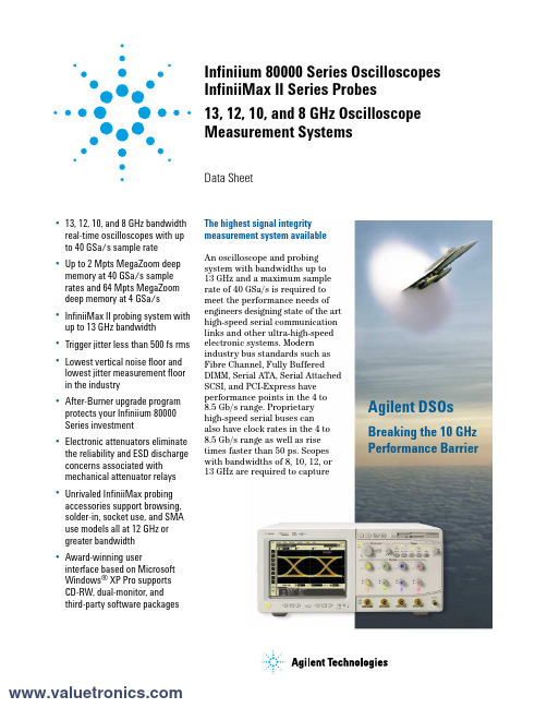
Infiniium 80000 Series OscilloscopesInfiniiMax II Series Probes13, 12, 10, and 8 GHz OscilloscopeMeasurement SystemsData Sheet•13, 12, 10, and 8GHz bandwidthreal-time oscilloscopes with upto 40GSa/s sample rate•Up to 2Mpts MegaZoom deepmemory at 40GSa/s samplerates and 64Mpts MegaZoomdeep memory at 4GSa/s•InfiniiMax II probing system withup to 13GHz bandwidth•Trigger jitter less than 500fs rms•Lowest vertical noise floor andlowest jitter measurement floorin the industry•After-Burner upgrade program protects your Infiniium 80000Series investment •Electronic attenuators eliminate the reliability and ESD discharge concerns associated withmechanical attenuator relays •Unrivaled InfiniiMax probing accessories support browsing,solder-in, socket use, and SMAuse models all at 12GHz orgreater bandwidth•Award-winning userinterface based on MicrosoftWindows®XP Pro supportsCD-RW, dual-monitor, andthird-party software packagesAgilent DSOsBreaking the 10 GHzPerformance Barrier The highest signal integritymeasurement system availableAn oscilloscope and probingsystem with bandwidths up to13GHz and a maximum samplerate of 40GSa/s is required tomeet the performance needs ofengineers designing state of the arthigh-speed serial communicationlinks and other ultra-high-speedelectronic systems. Modernindustry bus standards such asFibre Channel, Fully BufferedDIMM, Serial ATA, Serial AttachedSCSI, and PCI-Express haveperformance points in the 4 to8.5Gb/s range. Proprietaryhigh-speed serial buses canalso have clock rates in the 4 to8.5Gb/s range as well as risetimes faster than 50ps. Scopeswith bandwidths of 8, 10, 12, or13GHz are required to capture2Benefitsthe frequency harmonics of such high-speed signals and make accurate and repeatable measurements on them.Agilent’s award-winning InfiniiMax probing system set the standard for probing systems and the rest of the oscilloscope industry is now following this trend-setting architecture. Agilent’s InfiniiMax II probing system takes thisinnovation to an unmatched level of performance and usability.U.S. Navy imagery used in illustration without endorsement expressed or implied.3/find/infiniimaxII45/find/infiniimaxIIKey trends in theelectronics market•Technologies with dramatically increased clock speeds and edge rates have emerged.•Very fast serial differential buses are being used to save board space, reduce power and provide better noise immunity.•Densely packed circuit boards,often with stacked daughter boards, increase the need to probe in very hard-to-reach places.Key benefits of the 80000 and InfiniiMax II Series•Up to 13GHz bandwidth can track even the fastest signal speeds.• A sample rate of up to 40GSa/s can measure high-speed differential buses reliably and repeatedly.•The innovative InfiniiMax II probing system supports even the most demanding mechanical access requirements without sacrificing performance.6•The full real-time bandwidth of the oscilloscope is supported by up to a 40GSa/s sample rate.•This industry-leading sample rate produces more accurate and repeatable measurements,avoiding measurement error and signal aliasing due to under sampling, as shown above. This is especially important for high-quality jitter measurements.•The combination of up to13GHz bandwidth and 40GSa/s sample rate makes the 80000Series ideal for designs that include: PCI-Express II, Serial ATA II/III, 6Gbs SAS, 4.25 and 8.5Gbs Fibre Channel, 4.8Gbs Fully Buffered DIMM, or other high-speed electronic signals.The DSO 80000 Series Produces Accurate and Repeatable Measurements5 Gb/s real-time eye diagram with DSO81004A 8 Gb/s real-time eye diagram with DSO81204A7/find/infiniimaxIIE2690A Timing Interval and Jitter Analysis software The Agilent E2690A Advanced Time Interval and Jitter Analysis Software, licensed from Amherst Systems Associates (ASA); offers the most powerful and comprehensive set of tools for exploratory debug of jitter, and it is remarkably easy to use. The E2692A Basic Time Interval and Jitter Analysis Software offers the basic tools you need for jitter debug with the same precision you get with the advanced version. Both advanced and basic software versions provide complete jitterdecomposition into its components – including deterministic, random, and total jitter – as well as AutoMeasure to provide quick insight.Jitter Application Software PackagesE2681A EZJIT Jitter analysis softwareIncludes the following key measurements:cycle-to-cycle jitter, n-cycle jitter, period jitter,time interval error, setup and hold time,measurement histograms, measurement trending, and jitter frequency spectrum.N5400A EZJIT Plus Jitter analysis softwareQuickly separate random and deterministic jitter components and estimate total jitter at low BER for standards compliance. Automatic clock recovery and pattern detection, an easy-to-use setup wizard and graphical display views integrated into the Infiniium oscilloscope software further simplify navigation and RJ/DJ analysis.Infiniium: “It’s like someone who sits down and actually uses a scope designed this one.”Steve Montgomery, Director of Engineering, Linx TechnologiesUp to 40 GSa/s sample rate on two channelssignificantly reduces the chances of aliasing,increases measurement accuracy, and delivers thefull real-time bandwidth of the oscilloscope on twochannels simultaneously.Four channels at 20GSa/s with 8GHz real-time bandwidth or full bandwidth equivalent time modes are also available.Get fast answers to your questions with the built-in information system. Infiniium’s task-oriented Setup Guide provides step-by-step instructions for several advanced measurements and procedures.See your signal more clearly with a large (8.4-inch) high-resolution color display. Infiniium’s bright TFT display with anti-glare coating lets you see the details of your signal from all angles.20 Gb hard drive, 3.5” 1.44 MB floppy drive and rear USB port make it easy to save setup files, data files, screen shots, etc.Identify anomalies easily with color-graded persistence, a colorful visual representation of waveform distribution.Label waveforms and add notes to your screen captures — Infiniium’s keyboard makes it easy.Drag and drop markers with your mouse or use the arrow keys.Easy access to advanced features like math functions and FFTs, is provided by the Windows-based graphical user interface. This GUI also gives you unique capabilities like drag-and-drop measurements and zooming, and offers a graphical equivalent to all front panel controls.Remote access with Web-enabled connectivity,e-mail on trigger, and GPIB over LAN allows you to access your scope from remote locations.64 Mpts acquisition memory at 4GSa/s sample rate on two channels allows you to capture long time windows at high resolution – such as identifying glitches due to a power supply start-up from reset.QuickMeas+ key gives you any five automated measurements with a push of a button. You can also configure this key to print/save screen shots, save waveforms, or load a favorite setup.8Zoom and search with instant response.Zoom into your signal using the horizontal scale knob and search through your waveform with the position knob. MegaZoom technology allows you to find your area of interest quickly and easily – even with 64 Mpts waveforms.Built-in CD-R drive on rear panel allows you to update the system software conveniently and can be used to install third-party application packages.9/find/infiniimaxIIHands-free operation with the Infiniium VoiceControl option. Just speak into the microphone to operate front-panel controls.Segmented memory acquisition mode captures bursting signals at maximum sample rate without consuming memory during periods of inactivity.Removable hard disk drive option is available for added data security.Install third-party software packages such as Excel, LabView, Agilent Vee, MATLAB®, anti-virus software, and more to perform customizedprocessing and automation of your oscilloscope or to make the scope compliant to the network environment of your company.An external monitor allows you to run third-party applications on a large, high-resolution display while using the scope’s built-in monitor for high-speed waveform display.Windows® XP Pro operating system.A familiar interface makes simple tasks simple.Infiniium’s analog-like front panel has a full set of controls color coded to the waveforms and measurements, making simple tasks simple.One-year standard warranty and a variety of Agilent support options protect your investment for the long term.10MHz reference clock can be input (optional) to or output (standard) from the scope to allow precise timebase synchronization with RF instruments or logic analyzers.A new 18 GHz, BNC-compatible connectorprovides a high signal fidelity connection to Agilent active probes, SMA adapters, and standard BNCs.AutoProbe interface completely configures your scope for use with the InfiniiMax probing system and previous generation Agilent active probes.10/100 Mbps LAN interface lets you easily print waveforms on networked printers, save your results on your office PC, share information with others,and control the scope over the Web.10Two new high-bandwidth InfiniiMax IISeries probe amplifiers have been added to the InfiniiMax product line. InfiniiMax I probe amplifiers and probe heads can also be used with DSO 80000 Series scopes for lower performance applications.InfiniiMax II: The World’s Best High-Speed Probing System Just Got Better12GHz Hi-BW solder-in differential probe head provides maximum bandwidth and minimizes capacitive loading to ≤210fF.Variable spacing from 0.2 to 3.3mm (8 to 130 mills).12GHz Hi-BW differential browser provides maximum bandwidth for hand-held or probe holder use. Variable spacing from 0.2 to 3.3mm (8 to 130 mills).InfiniiMax offers you the highest performance available for measuring differential andsingle-ended signals, with flexible connectivity solutions for today’s high-density ICs and circuit boards.InfiniiMax probes have fully characterized performance for all of their various probe heads.This includes:•Swept frequency response plot•Common mode rejection vs. frequency plot •Impedance vs. frequency plot •Time-domain probe loading plot •Time-domain probe tracking plotOne-year standard warranty on active probes and a variety of Agilent support options to choose from.Controlled impedance transmission lines in every probe head deliver full performance versus the performance limitations produced by traditional wire accessories.Probe interface software allows you to save the calibration information for up to 10 different probe heads per channel and will automatically retrieve calibration data for a probe amplifier as it is attached to the scope.High-input impedance active probes minimize loading, support differential measurements and DC offset, and can compensate for cable loss.Probe calibration software delivers the most accurate probe measurements, linear phaseresponse and allows various probe combinations to be deskewed to the same reference time.InfiniiMax II probe headsThe 54006A 7.5 GHz resistive divider probe is available as a low-cost probing alternative for casual inspection of signals.A flat frequency response over the entire probe bandwidth eliminates the distortion and frequency-dependent loading effects that are present in probes that have an in-band resonance.InfiniMax I probe headsProbe Performance Plots AvailableThe InfiniiMax II probe manuals contain an extensive set of performance plots (bandwidth, probe tracking, CMRR, step response, impedance) for various probe configurations. See the following web site for this information/manuals/scopes/01169-9700_man.pdfInfiniium 80000 Series Performance CharacteristicsInfiniiMax II Series Performance CharacteristicsOrdering InformationReturn to service center required U.S. List$10,000$17,000Ordering Information (continued)as power supplies, inverters, semiconductor measurements,500 MHz (with supplied 10073C passive probe)500 MHz (with 10073C passive probe and80000 Series oscilloscope)Take the frustration out of communications testing and prove your designs conform to industry standards with the E2625A Communications Mask Test Kit option. Infiniium’s familiar Windows interface makes it easy for you to access the masks you need and configure your tests.In addition, the E2625A Communication Mask Test Kit comes with a set of electrical communication adapters to ensure convenient, reliable and accurate connections to your device under test. Included are more than 20 industry standard ANSI T1.102 and ITU-T G.703 communication signal mask templates. Logic Analyzer/Oscilloscope Time-Correlation Fixture.E2699A N5391AThe Agilent Serial BERT generator N4901B (N4902B)option 200 provides high speed digital stimulus to yourdevice with PRBS or memory based pattern from150Mb/s up to 13.5Gb/s (7Gb/s). For mor information,see /find/pulse-generators.Product Web site Array For the most up-to-date andcomplete application and productinformation, please visit ourproduct Web site at:/find/infiniimaxII /find/infiniimaxIIAgilent Technologies’ Test and Measurement Support, Services, and AssistanceAgilent Technologies aims to maximize the value you receive, while minimizing your risk and problems. We strive to ensure that you get the test and measurement capabilities you paid for and obtain the support you need. Our extensive support resources and services can help you choose the right Agilent products for your applications and apply them successfully.Every instrument and system we sell has a global warranty. Two concepts underlie Agilent's overall support policy: "Our Promise" and "Your Advantage."Our PromiseOur Promise means your Agilent test and measurement equipment will meet its advertised performance and functionality. When you are choosing new equipment, we will help you with product information, including realistic performance specifications and practical recommendations from experienced test engineers. When you receive your new Agilent equipment, we can help verify that it works properly and help with initial product operation.Your AdvantageYour Advantage means that Agilent offers a wide range of additional expert test and measurement services, which you can purchase according to your unique technical and business needs. Solve problems efficiently and gain a competitive edge by contracting with us for calibration, extra-cost upgrades, out-of-warranty repairs, and on-site education and training, as well as design, system integration, project management, and other professional engineering services. Experienced Agilent engineers and technicians worldwide can help you maximize your productivity, optimize the return on investment of your Agilent instruments and systems, and obtain dependable measurement accuracy for the life of those products.For more information on Agilent Technologies’products, applications or services, please contact your local Agilent office. The complete list is available at:/find/contactus Phone or Fax United States:(tel) 800 829 4444(fax) 800 829 4433Canada:(tel) 877 894 4414(fax) 800 746 4866China:(tel) 800 810 0189(fax) 800 820 2816Europe:(tel) 31 20 547 2111Japan:(tel) (81) 426 56 7832(fax) (81) 426 56 7840Korea:(tel) (080) 769 0800(fax) (080) 769 0900Latin America:(tel) (305) 269 7500Taiwan:(tel) 0800 047 866(fax) 0800 286 331Other Asia Pacific Countries:(tel) (65) 6375 8100(fax) (65) 67556 0042Email:*****************Contacts revised: 05/05/05Product specifications and descriptions in this document subject to change without notice.© Agilent Technologies, Inc. 2005Printed in USA, May 12, 20055989-1487ENUS /find/emailupdates Get the latest information on the products and applications you select.Agilent T&M Software and ConnectivityAgilent's Test and Measurement software and connectivity products, solutions and developer network allows you to take time out of connecting your instruments to your computer with tools based on PC standards, so you can focus on your tasks, not on your connections. Visit /find/connectivityfor more /find/agilentdirectQuickly choose and use your test equipment solutions with confidence.Agilent Email UpdatesAgilent Direct。
2657A_DataSheet

S i d e T e x t S M U I N S T R U M E N T SH i g h p o w e r S o u r c e M e e r i n s t r u m e n tThe Model 2657A is a high voltage, high power, low current source measurement unit (SMU) instru-ment that delivers unprecedented power, precision, speed, flexibility, and ease of use to improve productivity in R&D, production test, and reliability environments. The Model 2657A is designed specifically for characterizing and testing high voltage electronics and power semiconductors, such Source or sink up to 180W of DC or pulsed power (±3000V@20mA, ±1500V@120mA)1fA low current resolutionTwo Measurement Modes: Digitizing or IntegratingPrecisely characterize transient and steady-state behavior, including rapidly changing thermal effects, with the two measurement modes in the Model 2657A. Each mode is defined by its independent analog-to-digital (A/D) converters.The digitizing measurement mode provides speeds up to 1µs per sample. The dual 18-bit digitizers allow you to capture voltage and current transients simultaneously. In the integrating measurement mode, the dual 22-bit integrating analog to digital converters allow more precise measurement of volt-age and current. Two A/D converters are used with each measurement mode, one for current and the other for voltage, that run simultaneously for accurate source readback that does not sacrifice test throughput.0.00080.00060.00040.00020.0000–0.0002–0.0004–0.0006–0.0008–0.0010–0.00120.000 0.005 0.010 0.0150.020 0.025Current VoltageThe dual high speed A/D converters will sample as fast as 1µs per point, enabling full simulta-neous characterization of both voltage and current.Expansion CapabilitiesThrough TSP-Link ® technology, the Model 2657A can be linked with other Series 2600A instruments to form a larger integrated system with up to 32 nodes. Precision timing and tight channel synchro-nization are guaranteed with built-in 500ns trigger controllers. The fully isolated, independent chan-nels of the SourceMeter instruments make true SMU-per-pin testing possible.High Power Device Test FixtureThe Model 8010 High Power Device Test Fixture provides safe and easy connections for testingp ackaged high power devices at up to 3000V or 100A. The Model 8010 provides connections for a high voltage SourceMeter instrument (Model 2657A), one or two high current SourceMeter instru-ments (Model 2651A), and three low power SourceMeter instruments (other Series 2600A or Model 4200-SCS SMU instruments). This allows devices with two terminals (diodes) or three terminals (tran-sistors) or even four or five terminals to be characterized safely and accurately. The Model 8010 has full interlock capability for up to six SourceMeter instruments. The Model 8010 has integrated pro-tection circuits that protect the low voltage SourceMeter instruments from high voltages the Model 2657A can output should a device fault occur. The Model 8010 includes both a high current (100A) and a high voltage (3000V) test socket. Various replacement test socket modules are available, includ-ing TO-247, TO-220, axial lead, and a blank socket module that allows building a custom socket. In addition to standard banana jumpers, the Model 8010 has rear-panel scope and thermal probe ports to simplify system integration.High Power System SourceMeter InstrumentACCESSoRIES AVAILABLE2657A-LIM-3Low Interconnect Module 2657A-PM-200 200V Protection Module 4299-6Fixed Rack Mount KitSHV- CA-553-x High Voltage Triax to SHV Cable (1, 2, 3m)HV- CA-554-x High Voltage Triax to Triax Cable (0.5, 1, 2, 3m)HV- CA-571-3 High Voltage Triax to Unterminated Cable HV- CS-1613 High Voltage Triax Feedthrough ConnectorACCESSoRIES SUPPLIED WITH THE 8010CA-558-2 25-pin D-sub Interlock Cable for 26xxA CA-560-x 4mm Black and Red Banana Cables, 8 in.CA-562-x 6mm Black and Red Banana Cables, 10 in.CA-563 BNC to Banana Cable, 9.5 in.CA-568-120 Safety Earth Ground Cable 8010-DTB Device Test Board with TO-247 Socket ACCESSoRIES AVAILABLE FoR THE 80108010-CTB Customizable Test Board8010-DTB-220 Device Test Board with TO-220 Socket (1.5kV)The Model 2657A can be combined with other Series 2600A and Model 4200-SCS SMUs to support multi-terminal test capability. The Models 2657A-PM-200 Protection Module and 2657A-LIM-3 Low Interconnect Module make it easier to connect multiple instru-ments to a probe station safely (not required for connecting to the Model 8010 High Power Device Test Fixture).Model 2657A rear panel.Model 8010 High Power Device Test Fixture.S i d e T e x t D C P o W E R S U P P L I E S S M U I N S T R U M E N T SM o d e l 2657A s p e c i f i c a t i o n sStandard Capabilities of Series 2600A InstrumentsEach Model 2657A includes all the features and capabilities provided in the other Series 2600A SourceMeter instruments:• Flexibility for use as either a bench-top I-V characterization tool or as a building block component of multiple channel I-V test systems.• TSP Express software to perform common I-V tests quickly and easily without programming or installing software.• ACS Basic Edition software for semiconductor component characterization (optional). ACS Basic Edition now features a “Trace” mode for generating a suite of characteristic curves.• Keithley’s Test Script Processor (TSP) technol-ogy supports creating and running custom user test scripts for high speed test auto-mation, as well as creating programming sequences that allow the instrument to oper-ate asynchronously without direct PC control.• Parallel test execution and precision timing when multiple Series 2600A instruments are connected together in a system.• LXI Class C compliance.• 14 digital I/O lines for direct connection to a probe station, component handler, or other automation tools.• USB port for extra data and test programs torage via USB memory device.Model 2657A Condensed Specifications141. For temperatures 0° to 18°C and 28° to 50°C, accuracy is degraded by ±(0.15 × accuracy specification)/°C.2. Derate accuracy specification for NPLC setting <1 by increasing error term. Add appropriate typical percent of range term for resistive loads using the table below.NPLC Setting 200 V and 500V Ranges 1500V and 3000 V Ranges 100 nA Range1 µA to 120 mARanges 0.10.01%0.01%0.01%0.01%0.010.08%0.07%0.1 %0.05%0.0010.8 %0.6 % 1 %0.5 %3. 18-bit ADC. Average of 1000 samples taken at 1µs intervals.4. For temperatures 0° to 18°C and 28° to 50°C, accuracy is degraded by ±(0.35 × accuracy specification)/°C.SUPPLEMENTAL CHARACTERISTICSTypical VolTage Source NoiSe: 0.005% of range.Typical curreNT Source NoiSe: 0.08% of range.Typical VolTage Source SeTTliNg: <1ms to 200V, <7ms to 3000V.Typical curreNT Source SeTTliNg: <5ms to 120mA, <200ms to 1µA.Specifications are subject to change without notice.Specifications are subject to change without notice.All Keithley trademarks and trade names are the property of Keithley Instruments, Inc. All other trademarks and trade names are the property of their respective companies.A G R E A TE R M E A S U R E O F C O N F I D E N C EKEITHLEY INSTRUMENTS, INC. ■ 28775 AURORA RD. ■ CLEVELAND, OH 44139-1891 ■ 440-248-0400 ■ Fax: 440-248-6168 ■ 1-888-KEITHLEY ■ BELGIUMSint-Pieters-Leeuw Ph: 02-3630040Fax: 02-3630064 info@keithley.nl www.keithley.nlCHINA BeijingPh: 86-10-8447-5556Fax: 86-10-8225-5018 china@ FRANCE Les UlisPh: 01-69868360Fax: 01-69868361 info@keithley.fr www.keithley.frGERMANY GermeringPh: 089-84930740Fax: 089-84930734 info@keithley.de www.keithley.de INDIABangalorePh: 080-30792600Fax: 080-30792688support_india@ www.keithley.in ITALYPeschiera Borromeo (Mi)Ph: 02-5538421Fax: 02-55384228info@keithley.it www.keithley.it JAPAN TokyoPh: 81-3-6714-3070Fax: 81-3-6714-3080 info.jp@ www.keithley.jp KOREA SeoulPh: 82-2-574-7778Fax: 82-2-574-7838keithley@keithley.co.kr www.keithley.co.kr MALAYSIA PenangPh: 60-4-643-9679Fax: 60-4-643-3794 sea@ NETHERLANDS SonPh: 040-2675502Fax: 040-2675509 info@keithley.nl www.keithley.nlSINGAPORE SingaporePh: 65-6747-9077Fax: 65-6747-2991 sea@ SWITZERLAND BruggPh: 41-56-460-7890Fax: 41-56-460-7879 info@keithley.ch TAIWAN HsinchuPh: 886-3-572-9077Fax: 886-3-572-9031 info_tw@ UNITED KINGDOM BracknellPh: 044-1344-392450Fax: 044-1344-392457 info@ 2657 TRIGGERING AND SYNCHRoNIZATIoN SPECIFICATIoNSTriggeriNg: Trigger in to Trigger out: 0.5µs, typical.SyNchroNizaTioN: Single- or multi-node synchronized source change: <0.5µs, typical.PRoGRAMMINGTeST ScripT Builder: Integrated development environment for building, running, and managing TSP scripts.TSp expreSS (embedded): Tool that allows users to perform common I-V tests quickly and easily without programming or installing software.SofTware iNTerface: TSP Express (Embedded), Direct GPIB/VISA, Read/Write with VB, VC/C++, VC#, LabVIEW, TestPoint, LabWindows/CVI, etc.SYSTEM ExPANSIoNThe TSP-Link expansion interface allows TSP-enabled instruments to trigger and communicate with each other. See figure below:uSB: USB 2.1 Host Controller, supports external data storage.coNTacT check: ± 50Wpc iNTerface: IEEE-488.1 and .2; LXI Class C Ethernet; RS-232.digiTal i/o iNTerface: Input/Output Pins: 14 open drain I/O bits. 5.25V max.power Supply: 100V to 250VAC, 50Hz–60Hz (auto sensing), 550VA max cooliNg: Forced air. Side and top intake and rear exhaust. eMc: Conforms to European Union EMC Directive.SafeTy: ETL listed (PENDING). Conforms to European Union Low Voltage Directive.warraNTy: 1 year.diMeNSioNS: 89mm high × 435mm wide × 549mm deep (3.5 in × 17.1 in × 21.6 in). Bench Configuration (with handle and feet): 104mm high × 483mm wide × 620mm deep (4.1 in × 19 in × 24.4 in).weighT: 9.98kg (22 lbs).eNViroNMeNT: For indoor use only.caliBraTioN period:One year.。
H.265标准
H.265H.265是ITU-T VCEG 继H.264之后所制定的新的视频编码标准。
H.265标准围绕着现有的视频编码标准H.264,保留原来的某些技术,同时对一些相关的技术加以改进。
新技术使用先进的技术用以改善码流、编码质量、延时和算法复杂度之间的关系,达到最优化设置。
具体的研究内容包括:提高压缩效率、提高鲁棒性和错误恢复能力、减少实时的时延、减少信道获取时间和随机接入时延、降低复杂度等。
H264由于算法优化,可以低于1Mbps的速度实现标清数字图像传送;H265则可以实现利用1~2Mbps的传输速度传送720P(分辨率1280*720)普通高清音视频传送。
中文名:H.265推出时间:2013年2月批准组织:国际电信联盟(ITU)开发公司:爱立信制定2012年8月,爱立信公司推出了首款H.265编解码器,而在仅仅六个月之后,国际电联(ITU)就正式批准通过了HEVC/H.265标准,标准全称为高效视频编码(High Efficiency Video Coding),相较于之前的H.264标准有了相当大的改善,中国华为公司拥有最多的核心专利,是该标准的主导者。
H.265旨在在有限带宽下传输更高质量的网络视频,仅需原先的一半带宽即可播放相同质量的视频。
这也意味着,我们的智能手机、平板机等移动设备将能够直接在线播放1080p的全高清视频。
H.265标准也同时支持4K(4096×2160)和8K(8192×4320)超高清视频。
可以说,H.265标准让网络视频跟上了显示屏“高分辨率化”的脚步。
可能在几个月内,你就能看到支持H.265解码的设备上市了(如智能手机、显卡等)。
H.264统治了过去的五年,而未来的五年甚至十年,H.265很可能将会成为主流。
传输码率H.263可以2~4Mbps的传输速度实现标准清晰度广播级数字电视(符合CCIR601、CCIR656标准要求的720*576);而H.264由于算法优化,可以低于2Mbps的速度实现标清数字图像传送;H.265 High Profile 可实现低于1.5Mbps的传输带宽下,实现1080p全高清视频传输。
飞思卡尔半导体用户指南说明书

Freescale Semiconductor User’s Guide1OverviewThe Freescale Freedom development platform is a set of software and hardware tools for evaluation and development. It’s ideal for the rapid prototyping ofmicrocontroller-based applications. The Freescale Freedom KL26Z hardware (FRDM-KL26Z) is a capable and cost-effective design featuring a Kinetis L seriesmicrocontroller, the industry’s first microcontroller built on the ARM® Cortex™-M0+ core.FRDM-KL26Z can be used to evaluate the KL16 and KL26 Kinetis L series devices. It features a KL26Z128VLH4, a device boasting a maximum operating frequency of 48MHz, 128KB of flash, a full-speed USB controller, and numerous analog and digital peripherals. The FRDM-KL26Z hardware is form-factor compatible with the Arduino™ R3 pin layout, providing a broad range of expansion board options. The on-board interfaces include an RGB LED, a 6-axis digital sensor (combining a 3D accelerometer and 3Dmagnetometer), ambient light sensor, and a capacitive touch slider.The FRDM-KL26Z features the Freescale open standard embedded serial and debug adapter known as OpenSDA.Doc Number:FRDMKL26ZUGRev. 0, 10/2013Contents1.Overview . . . . . . . . . . . . . . . . . . . . . . . . . . . . . . . . . . . 12.Reference documents . . . . . . . . . . . . . . . . . . . . . . . . . 23.Getting started . . . . . . . . . . . . . . . . . . . . . . . . . . . . . . . 24.FRDM-KL26Z hardware overview . . . . . . . . . . . . . . 25.FRDM-KL26Z hardware description . . . . . . . . . . . . . 5FRDM-KL26Z User’s GuidebyFreescale Semiconductor, Inc.Reference documentsThis circuit offers several options for serial communications, flash programming and run-control debugging.2Reference documentsThe table below provides a list of reference documents for the FRDM-KL26Z hardware. All of these documents are available online at /FRDM-KL26Z.Table1. FRDM-KL26Z reference documentsFilename DescriptionFRDM-KL26Z Quick Start Package Quick Start Guide and supporting files for getting started with the FRDM-KL26Z FRDM-KL26Z User’s Guide This document—overview and detailed information for the FRDM-KL26ZhardwareFRDM-KL26Z Pinouts Spreadsheet of pin connections for all MCU pins. Includes pinout for the I/Oheaders, Arduino R3 compatibility chart, and OpenSDA MCU pinout.FRDM-KL26Z Schematics PDF schematics for the FRDM-KL26Z hardwareFRDM-KL26Z Design Package Zip file containing all design source files for the FRDM-KL26Z hardware OpenSDA User’s Guide Overview and instructions for use of the OpenSDA embedded debug circuit3Getting startedSee the FRDM-KL26Z Quick Start Package for step-by-step instructions to get started with the FRDM-KL26Z. See the Jump Start Your Design section on /FRDM-KL26Z for the Quick Start Package and software lab guides.4FRDM-KL26Z hardware overviewThe features of the FRDM-KL26Z include:•MKL26Z128VLH4 in a 64 LQFP package•Capacitive touch slider•FXOS8700CQ accelerometer and magnetometer•Tri-color (RGB) LED•Ambient light sensor•User push button•Flexible power supply options – USB, coin cell battery, external source•Battery-ready, power-measurement access points•Easy access to MCU I/O via Arduino™ R3 compatible I/O connectors•Programmable OpenSDA debug interface with multiple applications available including:—Mass storage device flash programming interface—P&E Debug interface provides run-control debugging and compatibility with IDE toolsFRDM-KL26Z hardware overview—CMSIS-DAP interface: new ARM standard for embedded debug interface—Data logging applicationFigure1 shows a block diagram of the FRDM-KL26Z design. The primary components and their placement on the hardware assembly are pointed out in Figure2.Figure1. FRDM-KL26Z block diagramFRDM-KL26Z hardware overview! (Figure2. FRDM-KL26Z feature call-outsFRDM-KL26Z hardware description5FRDM ‐KL26Z hardware description5.1Power supplyThere are multiple power supply options on the FRDM-KL26Z. It can be powered from either of the USB connectors, the VIN pin on the I/O header, an on-board coin cell battery, or an off-board 1.71-3.6V supply from the 3.3V pin on the I/O header. The USB and VIN supplies are regulated on-board using a 3.3V linear regulator to produce the main power supply. The other two sources are not regulated on-board. Table 2 provides the operational details and requirements for the power supplies.Table 2.Power supply requirementsNote that the OpenSDA circuit is only operational when a USB cable is connected and supplying power to J10. However, protection circuitry is in place to allow multiple sources to be powered at once.Figure 3 shows the schematic drawing for the power supply inputs and the on-board voltage regulator.Figure 3. Power supply schematicIn addition, regulated power can be supplied to J3 pin 10 from an external source through P5-9V_VIN by populating the board with an optional voltage regulator, e.g. a 7805 style regulator in a TO-220 package, thus providing a high current supply to external devices. To prevent voltage sag under a high load, C23,Supply Source Valid RangeOpenSDA Operational?Regulated on-board?OpenSDA USB (J7)5V Yes Yes KL26Z USB (J5)5V No Yes V in 4.3-9V No Yes 3.3V pin 1.71-3.6V No No Coin cell battery1.71-3.6VNoNoFRDM-KL26Z hardware descriptionC24, C25 & C28 should be populated with appropriately sized capacitors to match the regulator chosen. See Figure4.Figure4. Optional voltage regulator schematicTable3. FRDM-KL26Z power suppliesPowerDescriptionSupply NameP5-9V_VIN Power supplied from the V in pin of the I/O headers (J3 pin 16)P5V_SDA Power supplied from the OpenSDA USB connector (J10). A Schottky diode provides back drive protection.P5V_KL26Z Power supplied from the KL26Z USB connector (J6). A Schottky diode provides back drive protection P3V3_VREG Regulated 3.3V supply. Sources power to the P3V3 supply rail with an optional back drive protection Schottky diode.12P3V3_BATT Coin cell battery supply voltage. Sources power to the P3V3 supply rail with the option of adding a back drive protection Schottky diode.3P3V3Main supply rail for the FRDM-KL26Z assembly. May be sourced from P3V3_VREG, P3V3_BATT, or directly from the I/O headers (J3 pin 8).P3V3_KL26Z KL26Z MCU supply. Header J5 provides a convenient means for energy consumption measurements.4 P3V3_SDA OpenSDA circuit supply. Header J15 provides a convenient means for energy consumptionmeasurements.4P5V_USB Nominal 5V supplied to the I/O headers (J3 pin 10). Sourced from either the P5V_KL26Z or P5V_SDA supply through a back drive protection Schottky diode.FRDM-KL26Z hardware description5.2Serial and debug adapter (OpenSDA)OpenSDA is an open standard serial and debug adapter. It bridges serial and debug communications between a USB host and an embedded target processor as shown in Figure 5. The hardware circuit is based on a Freescale Kinetis K20 family microcontroller (MCU) with 128 KB of embedded flash and anintegrated USB controller. OpenSDA features a mass storage device (MSD) bootloader, which provides a quick and easy mechanism for loading different OpenSDA applications such as flash programmers, run-control debug interfaces, serial-to-USB converters, and more. See the OpenSDA User’s Guide for more details.Figure 5. OpenSDA high-level block diagramOpenSDA is managed by a Kinetis K20 MCU built on the ARM® Cortex™-M4 core. The OpenSDA circuit includes a status LED (D8) and a pushbutton (SW2). The pushbutton asserts a reset signal to the KL26Z target MCU. It can also be used to place the OpenSDA circuit into Bootloader mode. OpenSDA MCU RESET can be isolated from SW2 by cutting the trace between pins on J13. SPI and GPIO signals1By default the linear regulator, U1, is a 3.3V output regulator. However, this is a common footprint that would allow the user to modify the assembly to utilize an alternative device such as a 1.8V or 2.5V regulator. The KL26Z microcontroller has an operating range of 1.71V to 3.6V.2D2 is bypassed by J14. By default, the pins of J14 are shorted together, to reduce the voltage drop across D2. To use D2, cut the trace between the pins of J14.3If a coin cell battery is to be used, add a small amount of solder to the coin cell ground pad before adding the battery holder. Also, it is recommended to populate D1 as a protection diode when using a coin cell battery.4J5 and J15 are not populated by default. The two pins of these headers are in parallel with 0 Ω resistors. In addition, J5 is also in parallel with a 10 Ω resistor. To measure the energy consumption of the KL26Z, either a voltmeter or an ammeter may be used. To use a voltmeter, R3 (0 Ω) must be removed before connecting the voltmeter probes to the pins of J5. Both R3 and R2 (10 Ω) must be removed to measure current with an ammeter. For the OpenSDA MCU, energy consumption can be measured by removing R4 (0 Ω) and connecting ammeter probes to the pins of J15.FRDM-KL26Z hardware descriptionprovide an interface to the SWD debug port of the KL26Z. Additionally, signal connections are available to implement a UART serial channel. The OpenSDA circuit receives power when the USB connector J10 is plugged into a USB host.5.2.1Debug interfaceSignals with SPI and GPIO capability are used to connect directly to the SWD of the KL26Z. These signals are also brought out to a standard 10-pin (0.05”) Cortex Debug connector (J7). It is possible to isolate the KL26Z MCU from the OpenSDA circuit and use J7 to connect to an off-board MCU. To accomplish this, cut the trace on the bottom side of the PCB that connects J8 pin 1 to J8 pin 2. This will disconnect the SWD_CLK pin to the KL26Z so that it will not interfere with the communications to an off-board MCU connected to J7.Figure6. SWD debug connectorNote that J7 is not populated by default. A Samtec FTSH-105-02-F-D or compatible connector can be added to the J7 through-hole connector. A mating cable, such as a Samtec FFSD IDC cable, can then be used to connect from the OpenSDA of the FRDM-KL26Z to an off-board SWD connector.5.2.2Virtual serial portA serial port connection is available between the OpenSDA MCU and pins PTA1 and PTA2 of the KL26Z. Several of the default OpenSDA Applications provided by Freescale, including the MSD Flash Programmer and the P&E Debug Application, provide a USB communications device class (CDC) interface that bridges serial communications between the USB host and this serial interface on the KL26Z.5.3KL26Z microcontrollerThe target microcontroller of the FRDM-KL26Z is the KL26Z128VLH4, a Kinetis L series device in a 64 LQFP package. The KL26Z MCU features include:FRDM-KL26Z hardware description•32-bit ARM Cortex-M0+ core—Up to 48 MHz operation—Single-cycle fast I/O access port•Memories—128 KB flash—16 KB SRAM•System integration—Power management and mode controllers—Low-leakage wakeup unit—Bit manipulation engine for read-modify-write peripheral operations—Direct memory access (DMA) controller—Computer operating properly (COP) Watchdog timer•Clocks—Clock generation module with FLL and PLL for system and CPU clock generation—4 MHz and 32 kHz internal reference clock—System oscillator supporting external crystal or resonator—Low-power 1kHz RC oscillator for RTC and COP watchdog•Analog peripherals—16-bit SAR ADC w/ DMA support—12-bit DAC w/ DMA support—High speed comparator•Communication peripherals—Two 16-bit Serial Peripheral Interfaces (SPI)—USB dual-role controller with built-in FS/LS transceiver—USB voltage regulator—Two I2C modules—One low-power UART and two standard UART modules—One I2S module•Timers—One 6-channel Timer/PWM module—T wo 2-channel Timer/PWM modules—2-channel Periodic Interrupt Timer (PIT)—Real time clock (RTC)—Low-power Timer (LPTMR)—System tick timer•Human-Machine Interfaces (HMI)—General purpose input/output controllerFRDM-KL26Z hardware description—Capacitive touch sense input interface hardware module5.3.1Clock sourceThe Kinetis KL26 microcontrollers feature an on-chip oscillator compatible with three ranges of input crystal or resonator frequencies: 32-40 kHz (low freq. mode), 3-8 MHz (high frequency mode, low range) and 8-32 MHz (high frequency mode, high range). The KL26Z128 on the FRDM-KL26Z is clocked from an 8 MHz crystal.5.3.2USB interfaceThe Kinetis KL26 microcontrollers feature a dual-role USB controller with on-chip full-speed andlow-speed transceivers. The USB interface on the FRDM-KL26Z is configured as a full-speed USB device. J6 is the USB connector for this interface.Figure7. USB connector schematicIn order to enable USB host functionality on the FRDM-KL26Z, it is necessary to populate J9 and R8 as shown in Figure7. However, there is no electrical protection provided. Use the USB host functionality at your own risk.FRDM-KL26Z hardware description 5.3.3Serial portThe primary serial port interface signals are PTA1 and PTA2. These signals are connected to both the OpenSDA and to the J1 I/O connector. Note that the OpenSDA connection can be isolated from J1 by removing R13 & R14, if required.5.3.4ResetThe PTA20/RESET signal on the KL26Z128 is connected externally to a pushbutton, SW2, and also to the OpenSDA circuit. However, J13 has been provided to isolate the OpenSDA MCU from SW2. Isolating the RESET line allows a more accurate measurement of the target device’s power consumption in low-power modes. The reset button can be used to force an external reset event in the target MCU. The reset button can also be used to force the OpenSDA circuit into bootloader mode. See Section5.2, “Serial and debug adapter (OpenSDA), for more details.5.3.5DebugThe sole debug interface on all Kinetis L Series devices is a serial wire debug (SWD) port. The primary controller of this interface on the FRDM-KL26Z is the onboard OpenSDA circuit (see Section5.2, “Serial and debug adapter (OpenSDA)). However, an unpopulated 10-pin (0.05”) Cortex Debug connector, J7, provides access to the SWD signals. The Samtec FTSH-105-02-F-D or compatible connector can be added to the J7 through-hole debug connector to allow for an external debug cable to be connected.5.4Capacitive touch sliderTwo Touch Sense Input (TSI) signals, TSI0_CH9 and TSI0_CH10, are connected to capacitive electrodes configured as a touch slider. Freescale’s Touch Sense Software (TSS) provides a software library for implementing the capacitive touch slider.5.56-axis accelerometer and magnetometerA Freescale FXOS8700CQ low-power, six-axis accelerometer and magnetometer is interfaced through an I2C bus and two GPIO signals as shown in Table4. By default, the I2C address is 0x1D (SA0 pulled high).Table4. Accelerometer signal connectionsFX0S8700CQ KL26Z128SCL PTE24SDA PTE25INT1PTD0INT2PTD1FRDM-KL26Z hardware descriptionFigure 8. FXOS8700CQ schematic diagram5.6RGB LEDThree PWM-capable signals are connected to a red, green, blue LED, D7. The signal connections are shown in Table 5.Table 5. RGB LED signal connectionsFigure 9. RGB LED schematic diagramRGB LEDKL26Z128Red cathodePTE29Green cathodePTE31Blue cathodePTD511PTD5 is also connected to the I/O header on J2 pin 10 (also known as D13).FRDM-KL26Z hardware description5.7Ambient light sensorAn ambient light sensor is connected to ADC0_SE3 (PTE22). This sensor may be isolated from PTE22 by removing R36.5.8Input/Output connectorsThe KL26Z128VLK4 microcontroller is packaged in a 64-pin LQFP. Some pins are utilized in on-board circuitry, but many are directly connected to one of four I/O headers.The pins on the KL26Z microcontroller are named for their general purpose input/output port pin function. For example, the 1st pin on Port A is referred to as PTA1. The I/O connector pin names are given the same name as the KL26Z pin connected to it, where applicable.FRDM-KL26Z hardware descriptionNote that all pinout data is available in spreadsheet format in FRDM-KL26Z Pinouts. See Section2, “Reference documents” for details.5.9Analog reference voltageThe onboard ADC of the KL26Z128VLH4 MCU uses the Reference V oltage High (VREFH) and Reference V oltage Low (VREFL) pins to set high and low voltage references for the analog modules. On the FRDM-KL26Z, by default VREFH is attached to P3V3_KL26Z (3.3V Supply). VREFL is connected to GND. Figure10 illustrates this circuitry.Figure10. FRDM-KL26Z VREFH circuit schematicIf desired, VREFH can use a VDDA independent reference by adding R11 and a Zener diode (D6). R10 (0 Ω resistor) must be removed when implementing this option. Alternatively, VREFH can be attached to an external source through AREF by removing R10 and populating R9 with a 0 Ω resistor.5.10Arduino compatibilityThe I/O headers on the FRDM-KL26Z are arranged to allow compatibility with peripheral boards (known as shields) that connect to Arduino™ and Arduino-compatible microcontroller boards. The outer rows of pins (the even numbered pins) on the headers share the same mechanical spacing and placement as the I/O headers on the Arduino Revision 3 (R3) standard.FRDM-KL26Z hardware descriptionRefer to the FRDM-KL26Z Pinouts spreadsheet for a compatibility chart showing how all the functions of the KL26Z signals on the I/O connectors map to the pin functions available on the Arduino Uno R3.Document Number:FRDMKL26ZUG Rev. 010/2013Information in this document is provided solely to enable system and software implementers to use Freescale products. There are no express or implied copyright licenses granted hereunder to design or fabricate any integrated circuits based on the information in this document.Freescale reserves the right to make changes without further notice to any products herein. Freescale makes no warranty, representation, or guarantee regarding the suitability of its products for any particular purpose, nor does Freescale assume any liability arising out of the application or use of any product or circuit, and specifically disclaims any and all liability, including without limitation consequential or incidental damages. “Typical” parameters that may be provided in Freescale data sheets and/or specifications can and do vary in different applications, and actual performance may vary over time. All operating parameters, including “typicals,” must be validated for each customer application by customer’s technical experts. Freescale does not convey any license under its patent rights nor the rights of others. Freescale sells products pursuant to standard terms and conditions of sale, which can be found at the following address: /SalesTermsandConditions.How to Reach Us:Home Page:Web Support:/supportFreescale, the Freescale logo, and Kinetis are trademarks of FreescaleSemiconductor, Inc., Reg. U.S. Pat. & Tm. Off. ARM is the registered trademark ofARM Limited. ARM Cortex-M0+ is the trademark of ARM Limited. All other product orservice names are the property of their respective owners.© 2013 Freescale Semiconductor, Inc.。
- 1、下载文档前请自行甄别文档内容的完整性,平台不提供额外的编辑、内容补充、找答案等附加服务。
- 2、"仅部分预览"的文档,不可在线预览部分如存在完整性等问题,可反馈申请退款(可完整预览的文档不适用该条件!)。
- 3、如文档侵犯您的权益,请联系客服反馈,我们会尽快为您处理(人工客服工作时间:9:00-18:30)。
• F/A-18A-F, EA-18G F/A-18A- EA• ASN-RDA ASN• DASN Logistics • PEO TACAIR • PMA 265 • NAVAIRSYSCOM • Boeing, St Louis • GE – Lynne
• Use OPNAV Mission Essential Subsystems Matrix (MESM) • PMA 265 Systems IPT inputs
• Evaluate most effective way to mark assets based on availability, time constraints and cost • Identify who will mark items
• Requested Bell-Boeing costs • 2005 (Lot 9) advance acquisition contract already signed; will implement as practicable
– Looking for ways to expand UID implementation
• 30 Nov 2004 • 01 May 2005 • 31 Oct 2005 • 31 Oct 2010
• To Meet Oct 2010 Compliance Requirement
•
Budget Impacts
• Funding requirement unknown; not identified in FY 05/06/07 Budgets • Resource requirements will be submitted in POM 08 • Will affect rate of UID implementation
• ROM Submittal 9/30/04
– Scoped to meet draft NAVAIR policy to mark only items with MIL-STD 130 nameplate (341 items) – ~90% of items from subcontractors – ~20% of subs responded with input for ROM – Lot 10 ROM: > $25M – PR-07 Issue submitted to modify Lot 10 – Bell-Boeing requested NAVAIR & OSD support Supplier Conference
PMA 265 – F/A-18 F/AUID Compliant Nameplate
PMA 265 – F/A-18 F/AUID Program Overview
• Supporting Infrastructure Aspects
• OEMs/Suppliers
• Utilize PBL contracts, as appropriate
• • • • F/A-18A-D F/A-18AF/A-18 E/F F/AEA-18G EAFIRST -
Mr John Young Mr Nicholas Kunesh RDML Dave Venlet CAPT Donald Gaddis VADM Wally Massenburg Air Vehicle Systems GFE Engines
• NADEP
• Utilized for sample marking and evaluation of marking technology on assets • Evaluate for use as a partner to mark assets through PBL, if appropriate
• NAVAIR Program Office (IPTs, Tiger Teams, PETs etc.)
• Centralized Support/Management Activity under Mission Systems Logistics Lead • As needed support from other Program Office teams • Coordinate with NAVAIR and Navy UID Leads • MOU/MOA with other PMAs for GFE etc.
• Fleet
• Support needed for Carriers/Shore Stations/Squadrons
V-22 UID Anecdote
• V-22 DAB Brief July 2004
– Anticipated earliest possible implementation for full compliance via 2006 contract (lot 10)
• • • • tiger team Vendors OEM Depot
• Organic • Commercial
• • • •
Coordinate best c) Coordinate implementation schedule Add to Registry as change occurs Repeat for next level of priority
PMA 265 – F/A-18 F/AUID Program Overview
• Schedule Overview
• • • • • • • December 2003 08 July 2004 15 July 2004 11 Aug 2004 27 Oct 2004 10 Nov 2004 12 Nov 2004 E/A-18G SDD Contract Let w/ UID Requirement E/APMA 265 Designated a UID POC – Tracy Moran Held PMA 265 UID Strategy Session Developed Standard F/A-18 E/F/G UID SOW F/AHeld F/A-18 UID/RFID Industry Day at Boeing F/AUpdated UID SOW to SOO w/ Industry Inputs Establish a Legacy Item UID Review team and Determine Mission Critical Systems for Model Plan Submit Model Plan Begin amending existing contracts with UID language as appropriate Physically begin marking Legacy equipment Meet UID compliance on all assets
In-Service/Out of Production InFRP SDD Program E/F PBL for Product Support
PMA 265 – F/A-18 F/AUID Program Overview
• UID Re-Engineering Processes Re• Identify mission critical systems