Parasitics in VLSI Circuits and the Role of Layout Verification
小学上册第十一次英语第3单元期末试卷[含答案]
![小学上册第十一次英语第3单元期末试卷[含答案]](https://img.taocdn.com/s3/m/a40e9a64b42acfc789eb172ded630b1c58ee9b7c.png)
小学上册英语第3单元期末试卷[含答案]英语试题一、综合题(本题有50小题,每小题1分,共100分.每小题不选、错误,均不给分)1 My grandpa enjoys telling ____.2 The __________ (政治运动) can lead to social change.3 The penguin waddles on the ______ (冰). It is very ______ (可爱).4 We should learn about ______ (植物的) importance.5 The chemical formula for sodium acetate is _______.6 A bee gathers _______ from flowers to create delicious honey.7 How many months are in a year?A. TenB. ElevenC. TwelveD. Thirteen答案:C8 The __________ (历史的视角) can change over time.9 What do we call a scientist who studies the effects of pollution?a. Environmental scientistb. Ecologistc. Biologistd. Chemist答案:a10 Plants need ________ (水) to survive.11 A hot spot is a location where magma rises from deep within the ______.12 The dog is ___ (digging/sitting).13 The chemical formula for mercury(II) chloride is ______.14 Atoms are primarily made up of _____.15 My toy ____ can talk and tell stories. (玩具名称)16 I like to __________ (动词) my __________ (玩具名) with my friends.17 What is 100 25?a. 75b. 80c. 85d. 90答案:a18 A chemical change is usually difficult to _______.19 The concept of ecosystem demonstrates the interaction between living and ______ things.20 What is the name of the first satellite sent into space?A. Apollo 11B. SputnikC. Voyager 1D. Hubble21 Planting a variety of species can create a more resilient ______. (种植多样的物种可以创造出更强韧的生态系统。
海底两万里中物理学的句子
海底两万里中物理学的句子英文回答:Physics plays a significant role in Jules Verne's novel "Twenty Thousand Leagues Under the Sea." As the story follows the adventures of Professor Aronnax, Ned Land, and Conseil aboard the Nautilus, many instances highlight the application of physics principles.One example is the concept of buoyancy. The Nautilus, being a submarine, must maintain neutral buoyancy to navigate underwater. This is achieved by adjusting the amount of water in the ballast tanks. By controlling the density of the Nautilus, Captain Nemo ensures that the upward force exerted by the water equals the downward force of the submarine, allowing it to float at a desired depth. This demonstrates Archimedes' principle, which states that an object immersed in a fluid experiences an upward buoyant force equal to the weight of the fluid it displaces.Another physics concept explored in the novel is pressure. As the Nautilus dives deeper into the ocean, the pressure increases significantly. The characters experience this firsthand when they descend to great depths and feel the pressure on their bodies. This aligns with Pascal's principle, which states that pressure is transmitted uniformly in all directions in a fluid. The immense pressure at great depths is a result of the weight of the water above pressing down on the submarine.Furthermore, the novel touches upon the principles of electricity and magnetism. The Nautilus is powered by electricity, and Verne describes the use of electric motors to propel the submarine through the water. The concept of electromagnetism is also evident in the use of magnetic fields to navigate and detect underwater objects. These applications of physics showcase the integration of scientific knowledge into the fictional world of the Nautilus.中文回答:物理学在朱尔·凡尔纳的小说《海底两万里》中起着重要的作用。
Integrated-circuit

Integrated circuitIn electronics,an integrated circuit (also known as IC, microcircuit, microchip, silicon chip, or chip)is a miniaturized electronic circuit (consisting mainly of semiconductor devices, as well as passive components) that has been manufactured in the surface of a thin substrate of semiconductor material。
Integrated circuits are used in almost all electronic equipment in use today and have revolutionized the world of electronics.Integrated circuits were made possible by experimental discoveries which showed that semiconductor devices could perform the functions of vacuum tubes,and by mid—20th—century technology advancements in semiconductor device fabrication。
The integration of large numbers of tiny transistors into a small chip was an enormous improvement over the manual assembly of circuits using electronic components. The integrated circuit's mass production capability,reliability, and building—block approach to circuit design ensured the rapid adoption of standardized ICs in place of designs using discrete transistors。
超大规模集成技术_翻译
外文原文:VLSI TechnologyOne of the key inventions in the history of electronics,and in fact one of the most important inventions ever period,was the transistor.It was invented by Bell Laboratories in 1948.In short,a transistor is a device that conducts a variable amount of electricity through it,depending on how much electricity is input to it.In other words,it is a digital switch.However,unlike the vacuum tube,it is solid state.This means that it doesn’t change its physical form as it switches.There are no moving parts in a transistor.The advantages of the transistor over the vacuum tube were enormous.Compared to the old technology,transistors were much smaller,faster, and cheaper to manufacture.They were also far more reliable and used much 1ess power.The transistor is what started the evolution of the modern computer industry in motion.The transistor was originally a single,discrete device,which you could p1ace individually into a circuit much like any other.Today,some special-purpose transistors are still used that way.What allowed the creation of modern processors was the invention of the integrated circuit,which is a group of transistors manufactured from a single piece of material and connected together internally,without extra wiring.Integrated circuits are also called ICs or chips.A special material is used to make these integrated circuits.While most materials either insulate from electrical flow (air,glass,wood) or conduct electricity readily(metals,water),there are some that only conduct electricity a small amount。
英文原版薛定谔科普

英文原版薛定谔科普Quantum mechanics, as proposed by Austrian physicist ErwinSchrödinger, is a fundamental theory in physics that describes the behavior of particles at the smallest scales. It provides a mathematical framework for understanding the wave-particle duality of matter and the probabilistic nature of physical interactions. Although quantum mechanics is widely considered to be one of the most successful theories in science, it is also one of the most perplexing and counterintuitive.量子力学是由奥地利物理学家薛定谔提出的一种基本理论,描述了粒子在最小尺度上的行为。
它为理解物质的波粒二象性和物理相互作用的概率性提供了数学框架。
虽然量子力学被广泛认为是科学中最成功的理论之一,但也是最令人困惑和反直觉的。
One of the fundamental principles of quantum mechanics is the superposition principle, which states that a system can exist in multiple states simultaneously until it is measured. This idea challenges our classical understanding of physical reality, where objects are expected to have definite properties at all times. Thefamous thought experiment known as Schrödinger's cat illustrates this concept, where a cat trapped in a box is considered both alive and dead until the box is opened and observed.量子力学的一个基本原理是叠加原理,它表明一个系统可以同时存在多个状态,直到被测量出来。
钴硅化物薄膜的快速淀积外延生长的原子模型模拟

Atomic Simulation of Cobalt Silicide Film Growth by RapidDeposition Epitaxy∗Hao Shi, Min Yu†, Ru Huang, Xing ZhangInstitute of Microelectronics, Peking University Peking, China, 100871†E-mail:yum@AbstractThe research of cobalt silicidation has attracted much attention for its potential applications in VLSI circuits as interconnects, contacts, etc. In this paper, we put forward a new process model for the growth of CoSi2 film by RDE (Rapid Deposition Epitaxy) experiment and develop a smart program to simulate the film growth. In our model, we use a two dimensional mesh structure to describe the silicon substrate. The mesh structure is made up of path s which can be defined as a series of vectors. The properties of the path s such as start point, current state, etc. are recorded so that the diffusion and reaction of the moving atoms can be conveniently simulated, making the detailed physical analysis possible. The movements of the atoms are restricted on path s, and the state of the path s will influence the movement of the atoms. Diffusion or reaction of the atoms will occur with a certain probability, depending on the two variables Rate_Diffusion and Rate_Reaction which are defined in our model to describe the diffusion rate and reaction rate of the reacting atoms, respectively. The simulation results and the discussions are also presented,which show that the CoSi2 growth by RDE is a diffusion-controlled process.Keywords: cobalt silicide, simulation, film growth1.IntroductionCobalt silicide films are of great interests as interconnects, contacts in the state-of-the-art IC technology, especially when the device feature size is scaled down. This is due to its good properties such as low resisitivity (~1 µΩ cm) and small lattice misfit to silicon (~1.2% at room temperature), which can effectively reduce the parasitic series resistance. Besides, the growth of cobalt silicide can ensure the self-alignment of source and drain. As for the preparation of cobalt silicide films, there are various processes which can form CoSi2 with good quality. But these traditional processes are complex and need strict fabrication conditions. RDE experiment, which is the deposition of Co atoms very slowly onto a hot silicon substrate to form CoSi2 directly, is a relatively simple preparation process. Good CoSi2 films can be achieved when using low deposition rates (~0.1Å/s) combined with relatively high substrate temperatures (~600℃) during deposition. Thus, this is a very promising process for fabrication of cobalt silicide. It is of great interest to establish a model for the computer simulation of the cobalt silicide film growth by RDE experiment, especially in the case of atomic simulation model. In this paper, based on the properties and mechanisms of cobalt silicide film growth in RDE experiment [1-13], we put forward a new process model to simulate the CoSi2 film growth and develop a physically-based computer program. In our model, by introducing a two dimensional mesh structure to describe the silicon substrate, we can simulate the behavior of the Co atoms such as diffusion and reaction conveniently. The program is a very smart one which has a high computing efficiency, and it can be adapted easily to simulate the film growth in a more considerate way. Our program can simulate the uniform growth of CoSi2. The simulation results show that the CoSi2 growth is a diffusion controlled process. The growth rate is initially approximately linear with∗Supported by Specialized Research Fund for the Doctoral Program of Higher Education(20020001017) and National Natural Science Fund (No. 90207004)time and then proceeds at t1/2 dependence, implying that the diffusion of Co or Si through the silicide layer is the limiting mechanism.2.Growth of cobalt silicide filmIn Co/Si system, Co atoms react with Si atoms to form three kinds of compounds: Co2Si, CoSi and CoSi2 [2-4]. CoSi2 is usually the last phase to form in solid-phase reaction and is the phase needed in integrated circuit fabrication. The concentration of the reacting atoms and temperature of the system are important factors that influence the phase formation [5]. As is described in concentration control phase selection theory (CCPS) in which the concept of an effective heat of formation is used, the CoSi2 phase will form directly as the first phase if the effective concentration of Co at the growth interface is lower than about 33 at.% Co, where CoSi2 has the most negative effective heat of formation [6,12,13]. This is in agreement with the result in RDE experiment, in which Co atoms are deposited onto a hot silicon substrate, allowing immediate reaction of the materials. CoSi2 is formed directly, avoiding the formation of the intermediate cobalt silicide phases.The key point of this method is limiting the Co flux (i.e.deposition rate) to a value low enough to avoid the nucleation of polycrystalline Co rich silicides. In other words, one must allow the complete reaction of a Co layer with Si before the next layer is supplied to the surface. Consequently, both the deposition rate and substrate temperature are expected to play an important role in the crystalline quality of the CoSi2 layer. Based on RDE experiment, we develop a model for the growth of CoSi2 film which can be described as below (as seen in Fig.1):1.Co atoms are deposited onto a hot silicon substrate (about 600℃) at a very low rate (about 0.1Å/s).2.Co atoms diffuse randomly in the silicon substrate, and react with Si atoms to form CoSi2 directly,skipping the intermediate cobalt silicide phases in the formation sequence.3.The deposition rate and substrate temperature are two critical factors that influence the growth ofCoSi2 in this model. It is essential to keep the deposition rate of Co to a value low enough to allow the complete reaction of a Co layer with Si before the next layer is supplied to the surface. The substrate temperature determines the diffusion rate and reaction rate of Co atoms, and should be high enough to keep the balance of the Co supply and consumption.Co(a)Co(b)Fig.1 Formation of CoSi2 by RDE experiment. (a) Co atoms are deposited very slowly on a hot Si substrate.(b) Co atoms react with Si atoms to form CoSi2 directly.In this model, the main idea is concentration determination [5]. On one hand, the gradient of concentration affects the diffusion. On the other hand the reaction rate affects the concentration of the reacting particles. So the diffusion rate and reaction rate together determine the evolution of the system.3. Atomic simulation of cobalt silicide film growthA program using C++ language and object oriented programming method is developed to simulate the growth of CoSi2 film. The simulation is based on the RDE experiment in which CoSi2 forms directly. During the growth of the CoSi2 film in RDE experiment, the deposited Co atoms diffuse randomly in thesilicon substrate. A Co atom will move from one position to another with a certain probability. As for the Si atoms, they vibrate at the crystal positions in most cases. When Co atoms meet with the Si atoms, they can react to form CoSi2 as is described in RDE experiment. Thus, we introduce two parameters to describe the behavior of the Co atoms: Rate_Diffusion and Rate_Reaction, which describe the diffusion rate and reaction rate of the Co atoms in the silicon substrate, respectively.In order to simulate the behavior of this Co/Si system, we first establish a two dimensional mesh structure to describe the silicon substrate (as seen in Fig.2). The x axis is the width of surface window and y is depth. It is made up of a series of grids. All of the crystalline Si atoms are at the center of the grids. Each grid in the mesh stands for a Si atom, and all the Si atoms arrange orderly. Based on this mesh, we then introduce the concept of a path. Path is a vector in the mesh structure (as seen in Fig.2). The properties of a path is recorded such as the start point of the path, its directions, whether it is blocked or not, and whether the start point is occupied by an atom or not. Thus, we can use two series of path s to construct the whole mesh structure: the path s whose directions are positive x and the path s whose directions are positive y (as seen in Fig.3).Fig.2 A two dimensional mesh structure. Path, diffusion trace and CoSi2 are shown, respectivelyFig.3 Mesh structure is made up of two series of paths: the paths whose directions are positive x and thepaths whose directions are positive y.Now we describe how a Co atom can diffuse and react in this mesh structure. We define that Co atoms can only move on the path s. In other words, they can not enter into the grids. When a moving direction is given, the Co atom which occupies the start point of a path will move along the direction. If the path is blocked or the end point of the path is occupied by another Co atom, the Co atom can not pass through and has toselect another direction to move, or else it will move along to a new position, which is the start point of another path. In Fig.2, a possible diffusion trace is demonstrated. During diffusion, a Co atom can react with the Si atoms around with a certain probability. If a Co atom reacts with two Si to form a CoSi2, the related path is set as blocked and no Co atoms can pass through this path anyway. Thus, each blocked path stands for a CoSi2. In Fig 2, some formed CoSi2 represented by gray rectangles are shown. It is also shown that Co atoms can still diffuse between CoSi2 grains because not all path s can be blocked during the formation of a series of CoSi2 grains.Fig.4 Flow chart of the main simulation processThe main simulation process can be described as below (as is seen in Fig.4):1.Deposit a number of Co atoms on the surface of the substrate.2.Select a Co atom randomly from the deposited Co atoms. A random moving direction is given tothe atom.3.Determine whether the selected Co atom will diffuse or react. If diffuse, go to step 4, else go tostep 5.4.Call the function of Diffusion. Then go to step 6.5.Call the function of Reaction.6.Current simulation time increases by a TimeStep. TimeStep can be calculated by :∑=+=ni action Rate Diffusion Rate TimeStep 1)Re __(1It means the time consumed for a diffusion event or a reaction event. In the program, Rate_Diffusion and Rate_Reaction is usually given as about 1013/s, and n is the number of the Co atoms. Thus, the TimeStep is very small, about 10-15-10-13/s.7. Determine whether all the deposited Co atoms are reacted. If they are, deposit another number ofCo atoms, keeping the deposition rate low enough at same time.8. Determine whether the simulation time reached. If it is, the simulation is over, else go to step 2. In our program, the whole simulation process is driven by event. There is one event occur at a time. It can be a diffusion event or a reaction event. Each event will consume a certain period of time, and we call it a time step. When the program has dealt with one event, the whole simulation time will increase a time step, until in the end it reaches the stop time of the program. In our simulation, we make a simplification that the movements of the Si atom are neglected, as well as the defects and clusters in the Co/Si system.Improvement will be made in future work, taking all the above mentioned factors into account.(a)(b)(b) (c)Fig.5 Schematic drawings of the CoSi 2 film growth. Mesh size is 1000*200. Deposition rate is 0.1 Å /s. Diffusion rate and reaction rate are both 1013/s. (a) Simulation for 1 minutes. (b) Simulation for 6 minutes. (c) Simulation for 11 minutes. (d) Simulation for 16 minutes. “Normalized Si Depth” and “Normalized Si Surface” are the depth and width of the substrate, respectively, which are defined as the number of grids in the mesh structure.4. Results and discussionet the deposition rate as 0.1Å/s, and set the substrate temperature as 600℃. an be seen that the In our following simulation, we s Both the diffusion rate and the reaction rate of Co atoms are set as 1013/s, and the mesh size is set as 1000 grids for the silicon substrate depth and 200 grids for the silicon substrate width. In the following figures, we use the normalized length which can be defined as the quantity of the grids, as well as the normalized concentration which can be defined as the quantity of the CoSi 2 grains per grid length.Simulation for 1, 6, 11, and 16 minutes of the CoSi 2 growth are shown in Fig. 5. It c thickness of the CoSi 2 increases as the simulation time goes on. The interface between film and substrate is relatively uniform, indicating the regular growth of CoSi 2. In Fig.5 (a)-(d), the thickness of CoSi 2 film is about 10, 50, 90, 130 grids, respectively. The average growth speed is nearly a constant, about 8grids/min. In our program, since the TimeStep , which is defined as the time consumed for a diffusion event or a reaction event, is very small (about 10-15~10-13s), and the deposition rate is fairly slow, all the Co atoms will have been reacted before the next Co layer is deposited on the silicon substrate, and the program should wait quite a long time for the deposition of the next Co layer. In other words, the time interval of deposition Δt can be divided into two parts: Δt d&r and Δt w , which are the time consumed for diffusion and reaction of the Co atoms and the time consumed for waiting the deposition of the next Co layer, respectively. Δt d&r is much smaller than Δt w , and almost can be neglected. During the time interval of deposition Δt, there is enough time for all the Co atoms to react to form nearly the same number of CoSi 2, because the deposition rate is kept as a constant. Here we compute the growth speed of the CoSi 2 film with Δt, not Δt d&r .13/s13/sN o r m a l i z e d C o S i 2 C o n c e n t r a t i o nNormalized Si Depth 13/s13/sN o r m a l i z e d C o S i 2 T h i c k n e s sTime/min(a) (b)on rate is 0.1 Å /s. imulation for 20 minutes of the CoSi 2 growth is shown in Fig.6. Fig.6 (a) is the dependence of CoSi 2 dependence of time at the reacting front. Fig.6 Simulation of CoSi 2 growth for 20 minutes. Mesh size is 1000*200. Depositi Diffusion rate and reaction rate are both 1013/s. (a) Concentration of CoSi 2 vs. Si depth. (b) CoSi 2 thickness vs. time. “Normalized CoSi 2 Concentration” is the concentration of CoSi 2 which is defined as the quantity of the CoSi 2 molecule per grid depth, and “Normalized Si Depth” is the depth of the substrate which is defined as the number of grids in the mesh structure.S concentration on silicon depth. Fig.6 (b) gives the dependence of CoSi 2 film thickness on time. It can be seen that the result in Fig.6 (b) is in consistent with that in Fig.5.Fig.7(a) describes the increment of the CoSi 2 concentration in Total simulation time is 60 seconds. It can be seen that the CoSi 2 concentration becomes saturated as time goes by. Here, when the CoSi 2 concentration becomes saturated, the horizontal axis is actually the time Δt d&r , that is, the total time actually consumed for reaction and diffusion. When the reacting front reaches different substrate depth, the saturation of CoSi 2 concentration follows the similar tendency. In Fig.7, it can be observed that at the beginning of film growth at a certain substrate depth, the growth rate isapproximately linear with time. To further make clear the relationship between the growth rate of the CoSi 2 film and the growth time Δt d&r , we change the horizontal axis from t into t 1/2 and re-plot the curves in Fig.7(b), which shows that the middle segment of the curves is nearly linear. These results are in consistent with the conclusions reported in many literatures that the growth of cobalt silicide film is a diffusion-controlled process and the growth rate of the film is initially approximately linear with time and then proceeds at t 1/2 dependence.N o r m a l i z e d C o S i 2 C o n c e n t r a t i o nTime/sN o r m a l i z e d C o S i 2 C o n c e n t r a t i o nTime 1/2/s1/2(a) (b)Fig.7.ndence of CoSi 2 concentration on (a) time (b) squa ot of time.“Normalize e5. Conclusionprocess model for the growth of CoSi film by RDE (Rapid Deposition Epitaxy) thank Dr. Li Ming, and Mr. Xu Xinwen for their helpful discussions and valuable eferenceR. V . Knoell, S.P.Muarka, J. Appl. Phys. 57(6), (1985) 1880. ) 4301.) 283. s. 65(6), (1989) 2300., Appl. Phys. Lett. 74(21), (1999) 3137 uche, Applied Surface Science 91 (1995) 24.Depe re ro d CoSi 2 Concentration” is the concentration of CoSi 2 which is defined as the quantity of th CoSi 2 molecule per grid depth.In this paper, a new 2experiment is put forward. Computer program is developed to simulate the growth of CoSi 2 based on this model. In our program, we use a mesh structure to describe the silicon substrate, and the behavior of the Co atoms such as diffusion and reaction can be conveniently simulated. Reasonable simulation results are presented, which can be explained qualitatively. It can be concluded that the CoSi 2 film growth by RDE is a diffusion-controlled process. AcknowledgementThe authors wish to suggestions. Thanks support from Fujitsu Lab.R [1] A. Appelbaum, [2] u, J.W.Mayer, J. Appl. Phys. 49(7), (1978) 4005.[3] G .J.van Gurp, C. Langereis, J. Appl. Phys. 46(10), (1975[4] F. M. DHEURLE, C.S.PETERSSON, Thin Solid Films 128(1985[5] H.Miura, E.Ma, C.V .Thompson, J. Appl. Phys. 70(8), (1991) 4287.[6] W.Xia, C.A.Hewett, M.Fernandes, u, D.B.Poker, J. Appl. Phy [7] K.N.Tu, G .Ottaviani, R.D.Thompson, J.W.Mayer, J. Appl. Phys. 53(6), (1982) 4406. [8] G .J.van Gurp, W. F. van der Weg, D.Sigurd, J. Appl. Phys, 49(7), (1978)4011. [9] rie, R.T.Newman, J. Appl. Phys. 79(1), (1996) 153. [10] F .M.d’Heurle, S.-L.Zhang J. Appl. Phys. 87(11), (2000) 8216. [11] C rie, R.T.Newman, J. Appl. Phys. 87(11), (2000) 8218.[12] A .Vantomme, S.Degroote, J.Dekoster, G .Langouche, R.Pretorius [13] R .Pretorius, J.W.Mayer, J. Appl. Phys. 81(5), (1997) 2448.[14] A ndre Vantomme, Stefan Degroote, Johan Dekoster, Guido Lango。
delay-locked loop
ECE658Project-Delay Locked Loop DesignY.Sinan HanayDecember20,2007Chapter1IntroductionGeneration and distribution of clock signals inside the VLSI systems is one of the most important problems in the design of VLSI systems.Because of the process variations and interconnect parasitics,clock signals delays vary for di erent paths.The clock signals should have zero clock skew,that is to say all the clock signals should arrive at the inputs of registers at the same time.Otherwise latches and ip- ops get clock signal at di erent time instances.In order to circuit to operate correctly these di erences should be eliminated,ideally to zero.However it is not possible practically and10%of the clock cycle is expended in order to compensate for clock skew[1].To handle this problem,several solutions are proposed.One of which is usage of H-tree clock networks,in which con guration the distance to all circuit blocks is same thus the clock delay would be same.But this technique is hard to implement since the di erent fan-out requirements for di erent blocks and routing constraints.Also some CAD techniques and heuristics are used in the routing of the clock trees[6].The reduction of clock skew is one of the important problems in the VLSI design.Passive techniques such as clock network optimization techniques cannot completely reduce the clock skew[2].Phase-locked loops and delay-locked loops(DLL)are extensively used in VLSI circuits in order to decrease clock screw in the clock networks.DLL is a rst order loop that compares it`s input with a reference signal,than delay it`s output so that it can synchronize with the reference signal in a feedback fashion.DLL consists of4units:1.Phase Detector2.Charge Pump3.Filter4.Voltage Controlled Delay Line(VCDL)It`s working principle is as follows:First,phase detect block compares the reference clock signal with the output signal,depending on the di erence,if reference signal is leading the output Up(U)signal,else if the reference signal lagging the output signal Down(D)signal is asserted,and thus controls the delay line appropriately.VCDL adjusts the phase of the output signal proportional to the di erence between reference signal until the output signal is high%50of the time.In the gure below this principle is illustratedDLL DesignDLLs are notoriously di cult to build correctly.They require expertise in both feedback control systems and analog design.(N.Weste,D.Harris,A.Banerjee,2005:490[14])In this project some part of the design required Analog design and control systems background. DLLs can be classi ed in two groups:Analog and Digital DLLs.Digital DLLs have the advantage of higher exibility on supply voltage and low design complexity,while Analog DLLs o er better jitter[9],smaller area,low noise sensitivity and power consumption[8].The DLL consists of four main components,and they will be discussed in the following sections.1.1Phase DetectorIn order to deskew the clock, rst of all the skew must be known.This skew can be detected by the phase detectors.Its function is to detect the phase di erence between reference clock signal with the input clock signal.It takes these clock signals as input and produces an output that is proportional to the phase di erence.Phase detectors can be analog or digital.The rst phase detectors used in locked-loops was the linear multiplier phase detector,but as the PLLs became to implemented by digital components,digital phase detectors become popular[7].Simplest digital detector is an XOR gate,of which output is zero if the two inputs have same phase, and one as long as they are not equal.Phase detectors can be implemented digitally by J-K ip- ops.In this work,linear phase detector proposed in[4]is implemented is shown in Figure 1.1.Schematic and layout of the phase detector are shown in Figure1.2and1.3.Figure1.1:Phase Detector[4]Figure1.2:Phase DetectorFigure1.3:Layout of the Phase Detector1.2Charge PumpCharge pump design was one of the most complicated part of the DLL.The zero-o set charge pump that was mentioned in[5]was used.Figures1.4and1.5shows the schematic and layout of the charge pump.1.3FilterIn the history of the PLLs the rst phase detector was the linear multiplier phase detector[7].This multiply lters simply multiply the two inputs,and the desired result is reached byFigure1.4:Schematic of the Charge Pumpeleminating the higher frequency terms(odd-harmonics)in the product.This elemination,or ltering,is done by a low pass lter.In DLLs there is no need to include a low pass lter, instead a capacitor is used in order to integrate the phase error mainly,and thus increasing control voltage appropriately.So lter block is simply a capacitor,and a100fF capacitor was used.Increasing capacitor increases the lock time while decreases the bandwidth and the ripples on the control voltage,and decreasing it decreases lock time and increases the ripples.1.4Voltage Controlled Delay LineThe function of Voltage Controlled Delay Line(VCDL)is to delay the reference signal so that there is no skew between the output clock and reference signal.Its transfer function is simply, t d=κDL V filterwhere V filter is the ltered control input to the VCDL fromcharge pump,t d is the delay(the output)andκis the gain of VCDL.The minimum and maximum delay should be T cand1.5×T c2 For the voltage controlled line,there are several di erent techniques can be employed by analog or digital circuitry.The most common techniques use cascaded inverters.Inverters are used speci cally for the highest delay resolution.Two main usage of cascaded inverters are called: 1)Current-Starved Inverter Delay Line(in Figure1.6)and2)Shunt Capacitor Delay Stage(or Capacitor-Loaded Inverter Delay Line in Figure1.7[10].The delay range of Current-starved inverter circuit is higher than Shunt-capacitor circuit, however Shunt-capacitor transfer function is more linear and has lower gain than the that of Current-starved one[11,10].Lower gain is important because higher gain also ampli es the noise on the control voltage and may violate the stability[10],and linearity is important sinceFigure1.5:Layout of the Charge Pumpthe VCDL is modeled as linear with gainκdl.In this project I used a two-stage shunt-capacitor delay circuit for the reasons mentioned above.The reason for using two stage is because its noise immunity is higher.Increasing delay stages increasesκd,and which in turn will increase the jitter[13].I also implemented8stage VCDL but did not get satisfactory results.Figure1.8 shows the implemented VCDL`s transfer characteristics.Maximum achievable delay is around1.4ns.Figure1.6:Current-Starved Inverter Delay Line[10]Figure1.7:Shunt Capacitor Delay Stage[12]Figure1.8:Implemented VCDL`s Transfer Characteristics1.5SimulationsFigure1.11shows the simulation results for250MHz.As it can be seen from the gure,the locking is achieved aroung14th cycle with a static phase error of194ps when the clock is leading the reference signal.By decreasing charge pump`s output resistance it is possible to delay in a shorter time and suppressing the phase error.The results of decreasing charge pump`s output resistance is show in Figure1.12.It reveals that locking is achieved at6th clock cycle,but drawback here is the pulse-width of the clock is decreased too.Figures also show that in the lock state,both UP and DOWN signals are asserted for same duration,and the charge pump current rst increases then decreases by the same amount,e ectively putting no net charge to lter.Figure1.13shows the static error of192ps for DLL running at1GHz,when the clock is lagging the reference signal.Figure1.9:Layout of the VCDLFigure1.10:Layout of the DLLFigure1.11:DLL at250MHzFigure1.12:DLL at250MHzFigure1.13:DLL at1GHzResults and ConclusionsIn this section implemented DLL`s performance is compared with some previous works.This Work JSSC99[9]Thesis[8]Process0.25µm CMOS0.40µm CMOS0.18µm CMOS Max Operating Frequency800MHz667MHz700MHzMin Operating Frequency200MHz250MHz160MHzLock Time14cycles 2.9µs11cycles Static Phase Error192ps 80ps The DLL`s noise immunity can be improved by employing Self Biased techniques mentioned in which the process dependent variables in the system dynamics are eliminated[5].In another work,noise immunity is increased by using regulated Supply CMOS Bu ers[4].However since these techniques require di erential elements it increases the circuit complexityAppendixL VS Reports1)L VS Report of the Phase Detector@(#)$CDS:LVS version5.0.006/02/200321:50(cds11620)$Like matching is swapping is ing terminal names as correspondence piling Diva LVS rules...Net-list summary for/grads/h/hanay/Dokuman/proje/LVS/layout/netlist count18nets6 terminals14pmos16nmosNet-list summary for/grads/h/hanay/Dokuman/proje/LVS/schematic/netlist count18nets 6terminals14pmos16nmosTerminal correspondence points1DN2UP3ckin4ckref5gnd!6vdd!The net-lists match.instances layout schematicun-matched00rewired00size errors00pruned00active3030total3030nets un-matched00merged00pruned00active1818total1818terminals un-matched00matched but di erent type00total66Probe les from/grads/h/hanay/Dokuman/proje/LVS/schematicdevbad.out:netbad.out:mergenet.out:termbad.out:prunenet.out:prunedev.out:audit.out:prunenet.out:prunedev.out:audit.out:2)L VS Report of the Charge Pump@(#)$CDS:LVS version5.0.006/02/200321:50(cds11620)$Like matching is swapping is ing terminal names as correspondence piling Diva LVS rules...Net-list summary for/grads/h/hanay/LVS/layout/netlistcount13nets6terminals10pmos8nmosNet-list summary for/grads/h/hanay/LVS/schematic/netlistcount13nets6terminals10pmos8nmosTerminal correspondence points1DN2OUT3UP4VBN5gnd!6vdd!The net-lists match.instances layout schematicun-matched00rewired00size errors00pruned00active1818total1818nets un-matched00merged00pruned00active1313total1313terminals un-matched00matched but di erent type00total66Probe les from/grads/h/hanay/LVS/schematicdevbad.out:netbad.out:Probe les from/grads/h/hanay/LVS/layoutdevbad.out:netbad.out:mergenet.out:termbad.out:prunenet.out:prunedev.out:audit.out:2)L VS Report of the Voltage Controlled Delay Line@(#)$CDS:LVS version5.0.006/02/200321:50(cds11620)$Like matching is swapping is ing terminal names as correspondence piling Diva LVS rules...Net-list summary for/grads/h/hanay/LVS/layout/netlist count8nets5terminals2pmos 14nmosNet-list summary for/grads/h/hanay/LVS/schematic/netlist count8nets5terminals2pmos 6nmosTerminal correspondence points1gnd!2out3vctrl4vdd!5vinThe net-lists match.instances layout schematicun-matched00rewired00size errors00pruned00active168total168nets un-matched00merged00pruned00active88total88terminals un-matched00matched but di erent type00total55Probe les from/grads/h/hanay/LVS/schematicdevbad.out:netbad.out:mergenet.out:termbad.out:prunenet.out:Probe les from/grads/h/hanay/LVS/layout devbad.out:netbad.out:mergenet.out:termbad.out:prunenet.out:prunedev.out:audit.out:Bibliography[1]S.M.Kang,Y.Leblebici,CMOS Digital Integrated Circuits,McGraw Hill,2003.[2]Z.Zilic,Phase-and Delay-Locked Loop Clock Control in Digital Systems,.[3]J.M.Rabaey,A.Chandrakasan,and B.Nikolic,Digital Integrated Circuits,2nd ed.,PrenticeHall,2003.[4]S.Sidiropoulos,D.Liu,J.Kim,G.Wei,and M.Horowitz.Adaptive bandwidth DLLs andPLLs using regulated supply CMOS bu ers.In Proc.IEEE Symposium on VLSI Circuits, pages124 127,June2000.[5]Maneatis,et al.,"Low-Jitter Process-Independent DLL and PLL Based on Self-Biased Tech-niques,"IEEE Journal of Solid-State Circuits,Vol.31,No.11,November1996.[6]N.Menezes,S.Pullela,A.Balivada and L.T.Pillage,Skew Reduction in Clock Trees UsingWire Width Optimization,Proceedings Custom Integrated Circuits Conference,May1993.[7]R.E.Best,Phase-Locked Loops,6th Edition,McGraw Hill,2007.[8]C.Jia,A Delay-Locked Loop for Multiple Clock Phases/Delays Generation,Doctoral Thesis,Georgia Institute of Technology,2005.[9]B.W.Garlepp,K.S.Donnelly,J.Kim,P.S.Chau,J.L.Zerbe,C.Huang,C.V.Tran,C.L.Portmann,D.Stark,Y.-F.Chan,T.H.Leen,and M.A.Horowitz, A Portable Digital DLL for High-Speed CMOS Interface Circuits, IEEE J.Solid-State Circuits,vol.34,pp.632 644,May1999.[10]M.G.Johnson and M.E.Hudson, A variable delay line PLL for CPUcoprocessor synchro-nization, IEEE J.Solid-State Circuits,vol.23,pp.1218 1223,Oct.1988.[11]W.J.Dally and J.W.Poulton, Digital Systems Engineering ,Cambridge University Press,1998.[12]S.Liu,J.Lee and H.Tsao,"Low-power clock-deskew bu er for high-speed digital circuits",IEEE Journal of Solid-State Circuits,SC-34,pp.554-558,April1999.[14]N.H.E.Weste,D.Harris and A.Banerjee, CMOS VLSI Design A Circuits and SystemsPerspective ,Pearson Addison-Wesley,2005.[15]B.Razavi, Design of CMOS Analog Integrated Circuits ,McGraw Hill,2001.[16]P.Gray,P.J.Hurst,S.H.Lewis,R.G.Meyer, Analysis and Design of Analog IntegratedCircuits ,John Wiley Sons,Inc,2001.。
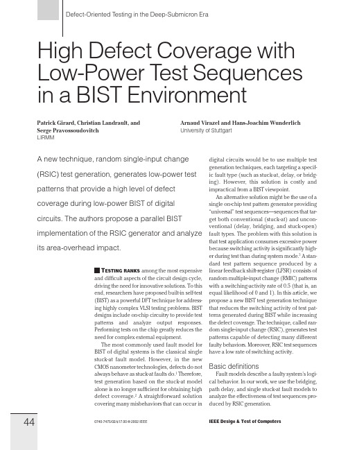
44 Defect-Oriented Testing in the Deep-Submicron Era High Defect Coverage with Low-Power Te
- 1、下载文档前请自行甄别文档内容的完整性,平台不提供额外的编辑、内容补充、找答案等附加服务。
- 2、"仅部分预览"的文档,不可在线预览部分如存在完整性等问题,可反馈申请退款(可完整预览的文档不适用该条件!)。
- 3、如文档侵犯您的权益,请联系客服反馈,我们会尽快为您处理(人工客服工作时间:9:00-18:30)。
Parasitics in VLSI Circuitsand the Role of Layout VerificationN.P.van der Meijs,A.J.van Genderen and T.Smedes Delft University of Technology,Faculty of Electrical Engineering P.O.Box5031,2600GA Delft,the NetherlandsAbstractIntegrated circuits consist of active devices and an interconnection network fabricated on a semi-conducting substrate.The properties of the interconnections and the substrate are increasingly important factors affecting the performance and operation of the circuit as a whole,amplifying the need for layout verifi-cation.In this paper,we discuss the behavior of IC interconnections and substrates,their electrical significance,and what constitutes an effective model for them.We conclude by reviewing the increased importance and new requirements of post-layout design verifica-tion.1IntroductionThe properties of IC interconnections and the substrate are increasingly important factors affecting the performance and operation of an IC.They must be considered in the IC de-sign loop.A failure to do so may result in lower than expected performance,higher than expected dissipation and/or unreliable or in-correct circuit behavior.In this paper,we will review appropriate models and scaling behavior of IC intercon-nections,based on the analysis in[1].Then, we will discuss two examples of undesired behavior caused by interconnect parasitics and the problem of substrate noise.We con-clude by discussing the new requirements of IC verification tools.2IC Interconnection Modeling The electromagnetic behavior of IC intercon-nections is governed by Maxwell’s equations. Because of the complexity of solving these equations,approximations are needed.An important approximation leads to the model-ing of IC interconnections as a set of lossy coupled transmission lines.They are usu-ally considered otherwise ideal,i.e.linear, frequency-independent,without skin effect, etc.Except for diffused conductors,this is usually an accurate approximation of IC in-terconnections when the operating frequen-cies are below1Ghz.However,in many cases(depending on e.g.the source,load, line length and frequency),much simpler ap-proximations are also accurate.In this sec-tion,we will discuss the applicability of such approximations.For that purpose,let usfirst introduce the fol-lowing notation:Length of an interconnection. ,,Resistance,capacitance,induc-tance of a line,per unit length. ,,Total resistance,capacitance,in-ductance of a line.The following equations are useful for calcu-lating the delay caused by a line.The RC delay of a lossy line is given by:(1) In the case of lossless and homogeneous transmission lines,supporting TEM waves,Table1.Typical IC interconnect parameters.20/m20m/m150aF/m0.5pH/m1.2cm/ns60and are related as(2) with and the permittivity and permeabil-ity of the medium,respectively.Although Equation(2)is only valid for a single line and IC interconnections are neither lossless nor homogeneous,it is usually an acceptable approximation.For TEM lines,the characteristic impedance and propagation speed are given by(3)(4) with the speed of light in vacuum and and the relative permittivity and perme-ability of the medium,respectively.On sil-icon IC’s,varies between and [2].Equations(2)and(4)can be combined to give the transmission line delay of a line:(5) For standard technologies a value ofaF/is a useful estimate for.With ,the above equations determine and as given in Table1.This table also contains typical values of other IC intercon-nect parameters,but not all types of parasitics are always equally significant.This depends, for example,on the following.Length of the interconnection.For exam-ple,we can neglect the inductive behavior of signal lines when.By compar-ing Equations(1)and(5),wefind that this is equivalent to or(6)Table2.Dominant circuit components for interconnections in typical technologies.technology,wire dominantcurrent level length circuit elements FET short Clow long C,RFET short C,R,(L)high long C,R,LBipolar short Clow long C,R,(L)Bipolar short C,L,(R)high long C,R,L Current level.For power lines,supporting large currents with large spikes,Faraday’s law can determine the significance of line in-ductance.The resulting noise is proportional to,and is called noise[1]. Signal rise time and driver impedance. When the signal rise time or ,the RC or LC delay of the line can be ignored,respectively.Furthermore, while obviously depends on the circuit characteristics and speed of the signal that drives the line driver,it also depends on the ratio between driver impedance and line impedance.It turns out that if, the line inductance can be ignored.The results of this section are summarized in Table2,which is adapted from[3].3IC Interconnection ScalingThe continuous improvement in the charac-teristics of integrated circuits is the result of scaling.With scaling,physical dimensions are reduced.As a result,the speed of the devices and the circuits improve.In order to avoid problems caused by strong electrical fields,voltages should also be reduced and doping levels increased.Since this would in-troduce many other practical problems,pro-portional scaling of voltages and doping lev-els is not strictly applied in practice.Yet,it is usually assumed in the analysis of scaling to more clearly illustrate its trend.Table3.Ideal scaling of MOS devices[4].parameter factorphysical dimensionssubstrate dopingvoltagesintrinsic device delaydevice areadevice powerBecause it ignores many second order effects, uniform scaling as defined above is called ideal scaling[4].Typical results are sum-marized in Table3.In what follows,we will present the scaling relations for interconnec-tion parasitics.Wefirst distinguish between local and global interconnections.Local interconnections are between individual devices,and their length is proportional to.Global interconnec-tions are between modules on a chip.Their length is proportional to the size of the chip, which increases with every new technology generation.When is used to denote this chip scaling factor,the length of the global interconnections is proportional to. Now,note that the unit-length interconnect resistance is inversely proportional to the interconnect cross-sectional area,and thus scales as.Furthermore,the unit-length interconnect capacitance is,in the case of ideal scaling,constant.Together with the scaling behavior of,the delay scaling of interconnections is thus described by.Since the intrinsic gate delay scales as,the ratio between the local interconnect delay and the gate delay increases by a factor of and the ratio of the global interconnect delay and the gate delay increases by a factor of. These results are summarized in Table4in the column labeled‘ideal’.(The column la-beled‘lateral’is explained below.)So,with ideal scaling,the performance of a chip is determined to an increasing extent by the interconnections.The problem is so se-vere that ideal scaling cannot strictly be ap-Table4.Scaling of interconnection delay.parameter ideal lateral unitylocal/global//plied.Instead,the lateral dimensions of the interconnections are scaled more than the ver-tical dimensions.Another reason to maintain the thickness of the interconnections is the occurrence of electromigration.When the current density in a metal line exceeds a certain material-dependent value,material of the line is dis-placed and the line can break,resulting in an open circuit.Thus,the current conduc-tion capability of interconnections must be maintained by(relatively)large vertical di-mensions.For purposes of illustration,we will consider the case in which vertical dimensions are not scaled at all,which we will call lateral scal-ing.The results are also indicated in Table 4,assuming that remains constant.While this is not strictly the case,it is justified for practical linewidths[5].The scaling of IC’s also deteriorates crosstalk and signal-to-noise ratios,and the detailed behavior again depends on what type of scal-ing is applied.For example,in the case of ideal scaling,is indepen-dent of,but in the case of lateral scaling,because of the change in cross-sectional shape of the conductors. Moreover,severe problems are also likely to occur with the on-chip power distribution. Both the resistive and inductive noise volt-age drops will increase because of the scal-ing properties of the interconnection parame-ters,but also because reduced voltages and increased frequencies both imply increased currents.The combined effect of increasedTable5.Scaling of signal-to-noise ratios. parameter ideal lateral1noise1/1/L noise1/1/25fFcrosstalkslownominalfast 50fFresponse 50fF50fF50fF25fF25fF25fF25fFFigure1.Five-conductor bus illustrating the effects of coupling capacitance.noise and decreased operation voltages ac-counts for severe deterioration of signal-to-noise ratios,as summarized in Table5.4ExamplesConsider the case offive parallel lines as shown in Figure1.Each line is driven by an inverter and different input patterns(ex-citations)are applied as shown.Each exci-tation has a label that indicates the resulting behavior at the far end of the middle line, and the result of SPICE simulations is pre-sented in Figure2.The waveforms show the output of the middle line in Figure1,labeled ‘response’.The timing and shape of the ex-citations is indicated by the signal‘’in Figure2.The simulation illustrates that the delay of a signal can depend on the wave-forms of neighboring lines.Also consider the CMOS driver layout in Fig-ure3.The parasitic drain and source resis-tances severely limit its performance,as can be seen from the SPICE simulation in Fig-ure4.This simulation compares the output waveform of the driver when interconnect re-sistance is ignored to that when the driver is modeled as in Figure5.This simulation as-sumes15nm gate oxide,40pF loadcapaci-Figure2.SPICE analysis of the network and excitations in Figure1.Figure3.Example of a CMOS driver layout.tance and75diffusion resistance.The signal rise time changes from15.4ns to27.4 ns.5Substrate ModelingThe traditional‘ideal ground plane’model of the substrate of VLSI chips is becom-ing invalid in a growing fraction of all the chips that are designed.Instead,its semi-conducting nature must be taken into account to predict various parasitic couplings between distant subcircuits.For example,in mixed signal IC’s,the digital parts can induce noise into sensitive analog parts.A typical example of substrate coupling is il-lustrated in Figure6.Because of the switch-ing actions in the digital part,a spike is intro-duced on the interconnect between the bias bondpad and the substrate contact.Via the resistive bulk,this spike reaches the feed-back resistor of the amplifier circuit,and de-Figure 4.SPICE simulation of the CMOS driver.vddvddvssvss outin Figure 5.Equivalent network of the CMOS driver.grades its signal-to-noise ratio.The problem can lead to rather unexpected system behav-ior if the digital noise is concentrated in a narrow frequency band,for example around the digital clock frequency.The problem can be seen as a sender-medium-receiver problem.The senders are the sources of ‘substrate pollution’.These senders can,for example,be the substrate contacts or the collector substrate junctions.Figure 6.Illustration of a substrate coupling problem.The medium is the substrate itself.Depend-ing on the fabrication technology,this can consist of a number of layers such as bulk layer,epi layer and channel-stopper layer,with particular doping levels.For VLSI ver-ification purposes,it will usually be accept-able to neglect minority carriers and to only consider the resistive nature of the substrate.With very high frequencies,however,the substrate must be treated as a lossy dielec-tric [2].The receivers are the sensitive nodes of the circuit.For example,the MOS drain-source current can be modulated by the sub-strate noise via the body effect.While substrate noise has been a practical problem before [6].it will become a far greater problem with scaling because of the following.(1)The senders will become stronger.For example,the noise in Figure 6scales as indicated in Table 5.(2)The receivers will be more sensitive.For ex-ample,with thin gate oxides the body effect increases.(3)The devices will be closer to-gether,giving stronger transmission.6ConclusionThe analysis in Section 2clearly demon-strates the growing significance of IC inter-connect parasitics.While it can be argued that the presented examples are somewhat extreme ,it can also be argued that many circuits cannot tolerate even a fraction of the parasitics assumed in that analysis.Such circuit examples are easily found in analog circuits,digital circuits employing precharge schemes and/or tri-state buffers,memory ar-rays employing sense amplifiers and so on.For example,a discussion of the capacitive coupling problem for bit lines in DRAM’s can be found in [7].In particular,the crosstalk example showed that large coupling capacitances between par-However,the CMOS driver example corresponds to a real industrial design that after fabrication did not perform as expected,because the interconnect resis-tance was neglected during design and simulation.allel lines can cause uncertain delay because signal waveforms can depend on the sig-nals on neighboring lines.This effect makes the problem of predicting electrical behavior more difficult,and virtually mandates exten-sive post-layout verification.Alternatively, large safety margins that reduce performance and/or increase area must be maintained dur-ing the design phase.With respect to substrate noise,note that it has been a practical problem before[6],but today it can even lead to the necessity of sep-arating analog and digital functions into two chips[8].However,when considering the scaling analysis in Section5together with the fact that the required precision of analog subcircuits generally increases,it is clear that substrate noise will become an even more im-portant design issue.Since parasitics are becoming much more im-portant and abundant,they must be extracted automatically,without requiring a designer to first identify them.Moreover,the extraction accuracy should be high in order not to re-quire uneconomically large safety margins. Consequently,a new generation of design verification tools is being developed[9].See, also,[5]and[10]and the references therein, as well as and[11]for a numerical technique for calculating a substrate model.Of course,the list of important(emerging) layout verification topics is not exhausted by the discussion in this paper.For example, the topics of reliability verification[12],ther-mal verification[13]and latchup verification [14]are also being studied.Interestingly,the problems of thermal and latchup verification are mathematically strongly related to that of substrate noise.Of course,IC designers can and will develop guidelines and techniques to cope with the problem.Nevertheless,new verification tools will help to obtain a competitive advantage. References[1]H.B.Bakoglu,Circuits,Interconnections andPackaging for VLSI.Reading,MA:Addison-Wesley,1990.[2]H.Hasegawa and S.Seki,“Analysis of Inter-connection Delay on Very High-Speed LSI/VLSIChips Using MIS Microstrip Line Models,”IEEE Trans.on Microwave Theory and Tech-niques,vol.MTT-32,no.12,pp.1721–1727,Dec.1984.[3] D.D.Ling and A.E.Ruehli,“InterconnectionModeling,”in Circuit Analysis,Simulation andDesign,2(A.E.Ruehli,ed.),Amsterdam,theNetherlands:Elsevier Science Publishers(NorthHolland),1987.[4]R.H.Dennard et.al.,“Design of ion ImplantedMOSFET’s with very small Physical Dimen-sions,”IEEE Journal of Solid State Circuits,vol.SC-9,pp.256–268,Oct1974.[5]N.P.van der Meijs,Accurate and Efficient Lay-out Extraction.PhD thesis,Delft University ofTechnology,Delft,the Netherlands,Jan.1992.[6]T.A.Johnson et.al.,“Chip Substrate ResistanceModeling Technique for Integrated Circuit De-sign,”IEEE Trans.on Computer Aided CircuitDesign,vol.CAD-3,no.2,pp.126–134,Apr.1984.[7]Y.Konishi et.al.,“Analysis of CouplingNoise Between Adjacent Bit Lines in MegabitDRAMS,”IEEE Journal of Solid-State Circuits,vol.SC-24,no.1,pp.35–42,Feb.1989.[8] B.M.J.Kup et.al.,“A Bit-Stream Digital-to-Analog Converter with18-b Resolution,”IEEEJournal of Solid-State Circuits,vol.SC-26,no.12,pp.1757–1763,Dec.1991.[9]N.P.van der Meijs and A.J.van Genderen,“Space User’s Manual,”Tech.Rep.ET-NT92.21,Delft University of Technology,Dept ofEE,Delft,NL,Apr.1992.[10] A.J.van Genderen,Reduced Models for the Be-havior of VLSI Circuits.PhD thesis,Delft Uni-versity of Technology,Delft,the Netherlands,Oct.1991.[11]T.Smedes,“Substrate Resistance Extractionfor Physics-based Layout Verification,”inIEEE/Prorisc Workshop on CSSP,this issue,Mar.1993.[12] C.Hu et.al.,“IC Reliability Simulation,”IEEEJournal of Solid-State Circuits,vol.SC-27,no.3,pp.241–246,Mar.1992.[13]K.Poulton et.al.,“Thermal Design and Simula-tion of Bipolar Integrated Circuits,”IEEE Jour-nal of Solid-State Circuits,vol.SC-27,no.10,pp.1379–246,Oct.1992.[14]J.H.Egbers.personal communication,1992.。